Water indicator Circuit to measure the level of any liquid
Simple automatic water level controller circuit
1. CIRCUIT
IDEAS
SIMPLE AUTOMATIC S.C. DW
IVEDI
WATER-LEVEL CONTROLLER
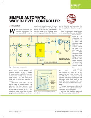
SUNIL KUMAR minal Vcc is at the bottom of the tank, sors in the OHT and connected the
sensor terminal L is just above the power supply, the circuit is ready to
W
ater-level controllers are bottom of the tank and sensor termi- use.
common nowadays. The nal H is at the top of the tank. After Since Vcc terminal is at the bottom
one described here is you have properly installed the sen- of the tank, when the water level falls
below sensor L,
timer IC2 is
triggered at pin
2 via inverters
N1 and N2 and
its output goes
high. As a re-
sult, the output
of timer IC2
goes high. Re-
lay RL1
energises and
the motor starts
filling water in
the tank. The
motor remains
‘on’ even when
the water level
crosses sensor
Fig. 1: Simple water level controller L.
As water in
built around timer NE555 and the tank rises to
inverter buffer CMOS IC CD4049. touch sensor H, timer IC2 is re-
It uses readily-available, low-cost triggered at pin 6 via inverters N3
components, and is easy to build and N4 and as a result, its output
and install on the over-head goes low. The relay de-energises and
tank (OHT) to prevent wastage of the motor stops filling water in the
water. tank. The motor remains ‘off’ even
The circuit works off a 12V bat- when the water level falls below sen-
tery or 230V AC mains using a 12V sor H.
adaptor. The three sensors built As water is consumed and its level
from non-corrosive metal are fitted falls below sensor L, the motor restarts.
to the OHT as shown in Fig. 2 and Thereafter, the cycle repeats.
connected to the circuit (Fig. 1) at ap- Fig. 2: Sensor installation in the overhead You can also manually start and
propriate terminals. Power supply ter- tank (OHT) stop the motor using switch S1.
WWW.EFYMAG.COM ELECTRONICS FOR YOU • FEBRUARY 2007 • 97