SlideShare a Scribd company logo
1 of 94
Download to read offline
GLC/GDC60VX, GLC/GDC70VX (D879)
SERVICE MANUAL CONTENTS
SECTION
PART
NUMBER
YRM
NUMBER
REV
DATE
FRAME............................................................................................................................ 524288189 0100 YRM 1316 08/13
GM 4.3L V-6 ENGINES................................................................................................... 524265337 0600 YRM 1251 05/14
COOLING SYSTEM........................................................................................................ 524223757 0700 YRM 1123 03/13
LPG FUEL SYSTEM (GM 4.3L)...................................................................................... 524262275 0900 YRM 1242 08/12
LPG FUEL SYSTEM GM 4.3L ENGINE WITH PSI........................................................ 550043871 0900 YRM 1556 04/14
THREE-SPEED POWERSHIFT TRANSMISSION REPAIR........................................... 524288194 1300 YRM 1317 03/13
TRANSMISSION REPAIR (DANA SPICER) 2X2........................................................... 524294873 1300 YRM 1343 03/14
DRIVE AXLE AND DIFFERENTIAL ASSEMBLY REPAIR (WET BRAKE)................... 524288199 1400 YRM 1318 12/13
STEERING AXLE............................................................................................................ 524223764 1600 YRM 1133 07/13
BRAKE SYSTEM............................................................................................................ 524262279 1800 YRM 1247 03/13
HYDRAULIC GEAR PUMP............................................................................................. 524223766 1900 YRM 1136 04/14
HYDRAULIC CLEANLINESS PROCEDURES............................................................... 550073240 1900 YRM 1620 12/14
MAIN CONTROL VALVE................................................................................................ 524223767 2000 YRM 1137 04/14
CYLINDER REPAIR (MAST S/N A513, A514, A613, A614, B513, B514)..................... 524294878 2100 YRM 1328 02/14
HIGH VOLTAGE SWITCH (HVS) IGNITION.................................................................. 524208014 2200 YRM 1097 05/14
WIRE HARNESS REPAIR.............................................................................................. 524223769 2200 YRM 1128 12/14
USER INTERFACE......................................................................................................... 524223770 2200 YRM 1130 12/14
USER INTERFACE......................................................................................................... 524223771 2200 YRM 1131 12/14
ELECTRICAL SYSTEM.................................................................................................. 524223772 2200 YRM 1142 04/14
MAST REPAIRS (S/N A513, A514, A613, A614, A702, A703, A704, A705, A706,
A707, A751, A752, B513, B514, B586, B587, B588, B589, B590, B591, B749,
B750, B751, B752, B753, B754)................................................................................ 524265342 4000 YRM 1250 02/14
METRIC AND INCH (SAE) FASTENERS....................................................................... 524150797 8000 YRM 0231 10/13
CALIBRATION PROCEDURES...................................................................................... 524223780 8000 YRM 1134 12/14
PERIODIC MAINTENANCE............................................................................................ 524288207 8000 YRM 1319 01/14
CAPACITIES AND SPECIFICATIONS........................................................................... 524288212 8000 YRM 1320 12/12
DIAGRAMS AND SCHEMATICS.................................................................................... 524329117 8000 YRM 1387 04/14
DIAGRAMS AND SCHEMATICS.................................................................................... 550001092 8000 YRM 1409 04/14
DIAGNOSTIC TROUBLESHOOTING MANUAL............................................................ 524221866 9000 YRM 1112 12/14
Service information for Cummins diesel engines can be ordered through the Hyster Literature Distribution Center.
9000 YRM 1112 ON CD
PART NO. 524329187 (12/14)
100 YRM 1316 Description
General
WARNING
The lift truck must be put on blocks for some types
of maintenance and repairs. The removal of the
following assemblies will cause large changes in
the center of gravity: mast, drive axle, engine and
transmission, and counterweight. When the lift
truck is put on blocks, put additional blocks in the
following positions to maintain stability:
• Before removing the mast and drive axle, put
blocks under the counterweight so the lift truck
cannot fall backward.
• Before removing the counterweight, put blocks
under the mast assembly so the lift truck cannot
fall forward.
The surface must be solid, even, and level when
the lift truck is put on blocks. Make sure any blocks
used to support the lift truck are solid, one-piece
units. See the procedure How to Put Lift Truck
on Blocks in the Operating Manual or the Periodic
Maintenance section for your lift truck.
If additional engine repairs are necessary for lift trucks
covered in this manual see:
• GM Engines, 4.3 Liter V-6 600 YRM 1251
• Kubota Diesel 3.8L Engines 600 YRM 1557
If additional transmission repairs are necessary for lift
trucks covered in this manual see:
• Powershift Transmission, Repair 1300 YRM 1129
• Powershift Transmission, Repair 1300 YRM 1529
• One and Two Speed Transmissions, Repair 1300
YRM 1569
• Three-Speed Powershift Transmission Repair
1300 YRM 1317
• Two-Speed Powershift Transmission Repair 1300
YRM 1343
This section contains the description of the frame (see
Figure 1) and connected parts. Procedures for remov-
ing and installing the counterweight, hood, overhead
guard, engine and transmission, and exhaust system
are found in this section. Checks for the operator re-
straint system and procedures for the repair of tanks
and installation of safety labels are also included.
Description
The frame is one weldment and includes the hydraulic
tank and fuel tank for gasoline or diesel fuel. See Fig-
ure 1.
There is a counterweight for each capacity of lift truck.
The counterweights are similar in appearance, but are
different weights. See Table 2.
The muffler is fastened to the frame inside the counter-
weight.
The overhead guard, cowl, and hood are installed on
the frame. The hood is connected to the frame with
hinges. Two gas-controlled springs provide assistance
when raising the hood and hold the hood in the open po-
sition. The floor plate and side covers can be removed
for access to the engine, transmission, and other com-
ponents.
1
Description 100 YRM 1316
1. COWL PLATE
2. FENDERS
3. HOOD MOUNTS
4. COUNTERWEIGHT MOUNTS
5. HYDRAULIC TANK
6. FUEL TANK (GAS OR DIESEL)
Figure 1. Frame
2
100 YRM 1316 Hood, Seat, Dash, and Side Covers Replacement
Hood, Seat, Dash, and Side Covers Replacement
REMOVE
1. Remove the floor mat and floor plate. See Figure 3.
2. Slide the seat to the closest position to the steering
column.
3. Fully tilt the steering column forward.
4. If your truck is equipped with an LPG tank, swing
the tank off to the side. Push in the bracket re-
lease pin, swing the tank and bracket out to the
side of the lift truck. If your truck is equipped with
a swing-out and drop-down LPG tank bracket (EZ
Tank Bracket), swing the tank down to the side of
the truck for ease of removal. See one of the fol-
lowing Service Manuals for procedures to swing
the LPG tank to the side.
LPG Fuel System, GM 4.3L Engine With GFI 900
YRM 1242 for lift truck models:
• GLC/GDC60VX, GLC/GDC70VX (GC/GLC/
GDC135VX, GC/GLC/GDC155VX) (C879,
D879)
LPG Fuel System, GM 4.3L Engine With PSI 900
YRM 1556 for lift truck models:
• GLC/GDC60VX, GLC/GDC70VX (GC/GLC/
GDC135VX, GC/GLC/GDC155VX) (D879, E879,
F879)
5. Raise the hood latch, unlatch and lift up the hood.
See Figure 2.
6. Remove the two capscrews holding the left and
right rear side panel to the frame. Remove the rear
side panel from the frame. See Figure 3.
3
Hood, Seat, Dash, and Side Covers Replacement 100 YRM 1316
NOTE: SWIVEL SEAT AND VENTED HOOD ARE OPTIONAL FEATURES.
A. SIDE VIEW OF HOOD AND SEAT
B. SIDE VIEW OF HOOD
C. BOTTOM VIEW OF HOOD
D. 3-D VIEW OF VENTED HOOD WITH SWIVEL
SEAT
1. SEAT
2. HOOD
3. FRAME
4. SEAT WIRE HARNESS
5. SEAT WIRE HARNESS CONNECTOR
6. CABLE CLIPS
7. HINGE SCREWS
8. GAS SPRING
9. ATTACHMENT HOLES ATTACHING HOOD TO
SEAT (SEMI-SUSPENSION)
10. SEAT WIRE HARNESS BRACKETS
11. SEAT LINER
12. HOOD LATCH
13. ATTACHMENT HOLES ATTACHING HOOD TO
SEAT (NON-SUSPENSION)
14. ATTACHMENT HOLES ATTACHING HOOD TO
SEAT (FULL SUSPENSION)
15. SPACER
16. FLANGE NUTS
Figure 2. Hood and Seat Arrangement
4
100 YRM 1316 Hood, Seat, Dash, and Side Covers Replacement
1. DEBRIS COVER
2. COUNTERWEIGHT COVER
3. RADIATOR COVER
4. LEFT SIDE REAR PANEL (GAS AND DIESEL
SHOWN)
5. RIGHT SIDE REAR PANEL
6. UPPER STEERING
COLUMN COVER
7. LOWER STEERING
COLUMN COVER
8. SEAL
9. FLOOR MAT
10. FLOOR PLATE
11. SPLASH SHIELD
(GAS AND DIESEL)
12. CAPSCREW
13. FOLD OVER NUT
14. SEAL PLATE ASSEMBLY
15. RIGHT SIDE FRONT
FENDER COVER
16. RIGHT SIDE STEP PLATE
17. RIGHT SIDE STEP PLATE
18. DASH ASSEMBLY
19. KICK PANEL
Figure 3. Side Covers, Floor Plate, and Cowl Components
5
Hood, Seat, Dash, and Side Covers Replacement 100 YRM 1316
7. Remove the two capscrews holding the left and
right fender covers to the front overhead guard leg.
Remove covers. See Figure 3.
8. Remove the four capscrews holding the left and
right front side panels to the frame. Remove pan-
els.
9. Fully lower the steering column.
10. Remove upper steering column cover by pulling
up on upper steering column cover to release the
latches (one on either side), and pulling cover away
from steering column. See Figure 4.
11. Remove the five fasteners (see Figure 4) securing
the dash to the top of the cowl. Remove the four
clips, located underneath dash, that attach the dash
to the kick panel. Lift to remove the dash.
12. Lift the kick panel to remove it from the truck. See
Figure 3.
13. Remove the three capscrews holding the seal plate.
Remove seal plate. See Figure 5.
14. Disconnect the seat wire harness connector. See
Figure 2.
CAUTION
When removing the seat from the hood, do not use
an impact wrench to remove the capscrews. Dam-
age can be caused to the threads on the screws and
in the holes.
15. If the seat is to be removed, and truck is equipped
with a non-swivel seat, remove the seat wire har-
ness from the seat wire harness brackets that are
attached to the underside of the hood. Remove the
cable clips from the seat wire harness. If truck is
equipped with a swivel seat, remove seat wire har-
ness from seat wire harness bracket attached to the
underside of the hood and behind the seat. See
Figure 2.
16. Remove the four flange nuts holding the seat to the
hood. Lift the seat off the hood. Pull the seat wire
harness through the hood. See Figure 2.
17. Remove the capscrews and washers at the top of
the gas springs. Remove gas springs from the
hood. See Figure 2.
18. Remove the hinge screws, located in the rear of the
hood.
19. Lift the hood from the truck. See Figure 2.
INSTALL
1. Place the hood onto the lift truck frame.
2. Install the hinge screws, located in the rear of the
hood, and tighten to 38 N•m (28 lbf ft). See Fig-
ure 2.
3. Align the holes in the gas springs with holes in the
hood. There are two sets of holes used to install
the gas springs to the hood, based on the type of
seat the installed on the lift truck. One set is for
installing the cylinder end of the gas springs and
the other set is for attaching the rod end of the
gas springs. Install capscrews and washers to at-
tach gas springs to the hood. Refer to Figure 6
and Table 1 for correct holes used to connect the
rod end of the cylinder, depending on the type of
seat installed on the lift truck. Tighten capscrews
to 19.2 N•m (170 lbf in).
6
100 YRM 1316 Hood, Seat, Dash, and Side Covers Replacement
NOTE: TOP VIEW OF DASH SHOWN.
A. INDICATES TO PULL UP TO UNLATCH
1. ALLEN SCREWS
2. COWL
3. UPPER STEERING COLUMN COVER
4. LOWER STEERING COLUMN COVER
Figure 4. Remove Dash From Cowl
7
Hood, Seat, Dash, and Side Covers Replacement 100 YRM 1316
1. CAPSCREWS 2. SEAL PLATE
Figure 5. Remove Seal Plate From Dash
8
100 YRM 1316 Hood, Seat, Dash, and Side Covers Replacement
NOTE: SEE TABLE 1 FOR HOLES TO USE TO ATTACH ROD END OF GAS SPRING.
A. LEFT SIDE
B. RIGHT SIDE
C. FULL SUSPENSION SEAT
D. NON-SUSPENSION SEAT
1. MOUNTING LOCATION FOR CYLINDER END OF GAS SPRING FOR NON-SUSPENSION SEAT
2. MOUNTING LOCATION FOR CYLINDER END OF GAS SPRING FOR SEMI OR FULL SUSPENSION SEAT
Figure 6. Gas Spring Installation
9
Hood, Seat, Dash, and Side Covers Replacement 100 YRM 1316
Table 1. Gas Spring Installation, Holes for Installing Rod Ends (See Figure 6)
Full or Semi Suspension Seat Non-Suspension SeatCounterweight
Type
Left Side Right Side Left Side Right Side
Standard
Counterweight
2 2 1 1
4. Install latch striker in highest slot position. Check
that latch striker is in center of jaws of hood latch
when hood closes. Open and close the hood to en-
sure that the center pin strikes the hood latch prop-
erly and that the stop screw contacts the frame. A
properly closed hood MUST click twice on the hood
latch. If the hood latch does not close properly,
loosen the capscrews on the back of the center pin
and adjust the center pin up or down as required for
correct alignment. See Figure 7.
5. Push down until hood just touches rubber bumper.
Make sure latch striker is still in center of hood latch.
Open hood and tighten capscrews for latch.
CAUTION
When installing the seat to the hood, do not use an
impact wrench to install the capscrews. Damage
can be caused to the threads on the screws and in
the holes.
6. Place the seat on the hood and thread the seat wire
harness through the hole in the hood. See Figure 2.
7. Align the holes in the seat with the holes in the
hood. Insert washers and capscrews. Tighten cap-
screws to 18 N•m (159 lbf in).
8. If truck is equipped with a non-swivel seat, tie cable
clips to seat wire harness and insert harness into
seat wire harness brackets under hood. If truck is
equipped with a swivel seat, secure seat harness
to bracket. See Figure 2.
9. Check operation of hood latch. Have an opera-
tor sit in the seat. Make sure hood is fully closed
(two clicks). Also check that hood touches rubber
bumper. If necessary, repeat Step 5.
10. Using three capscrews, Install seal plate. See Fig-
ure 5.
11. Install kick panel onto truck. See Figure 3.
12. Install dash and allen screws to top of cowl. See
Figure 4. Tighten capscrews to 0.5 to 0.6 N•m (5 to
6 lbf in).
13. Install four clips to attach the dash to kick panel.
See Figure 4.
10
100 YRM 1316 Hood, Seat, Dash, and Side Covers Replacement
14. Install upper and lower steering column covers by
connecting the two covers together and pressing
each side until latched.
15. Using four capscrews, install the left and right front
side panels to frame. See Figure 3.
16. Using two capscrews install the left and right fender
covers to front of overhead guard legs.
17. Using two capscrews, install the left and right rear
side covers to frame. See Figure 3.
18. Install the floor mat and floor plate.
19. If truck is equipped with an LPG tank, swing
LPG tank into position on back of counterweight.
See one of the following Service Manuals for
procedures to swing the LPG tank onto the coun-
terweight.
LPG Fuel System, GM 4.3L Engine With GFI 900
YRM 1242 for lift truck models:
• GLC/GDC60VX, GLC/GDC70VX (GC/GLC/
GDC135VX, GC/GLC/GDC155VX) (C879,
D879)
LPG Fuel System, GM 4.3L Engine With PSI 900
YRM 1556 for lift truck models:
• GLC/GDC60VX, GLC/GDC70VX (GC/GLC/
GDC135VX, GC/GLC/GDC155VX) (D879, E879,
F879)
20. Adjust the steering column and seat positions. 1. HOOD
2. HOOD LATCH
3. CENTER PIN
4. CAPSCREW
Figure 7. Hood Latch Adjustment
11
Steering Column 100 YRM 1316
Steering Column
DESCRIPTION
This section describes the repair procedures for the
steering column. The steering column assembly
mounts to the cowl inside the operator compartment
and is the mechanical connection between the steering
wheel and the steering control unit. The steering col-
umn includes the steering wheel, housing, bracket and
lower shaft. For lift trucks with gas and LPG engines,
bolts and bushings attach the steering column to the
cowl standoffs. For lift trucks with diesel engines, bolts,
bushings and isolators attach the steering column to
the cowl standoffs. See Figure 8.
STEERING COLUMN REPAIR
Remove
1. Put blocks on each side (front and back) of tires to
prevent lift truck from moving.
WARNING
Disconnect the battery before removing any covers
to avoid injury to personnel.
2. Attach a tag on battery connector or negative bat-
tery cable stating, DO NOT CONNECT BATTERY.
Move steering column to most FORWARD position.
CAUTION
If a puller tool is used to remove steering wheel
from steering column, be careful not to damage
horn wires.
NOTE: This procedure is for removal of all components
of steering column assembly. Not all components are
removed for a repair procedure. Do only those steps of
procedure necessary to remove required component.
NOTE: Tag wires prior to disconnect.
3. Remove horn button assembly and disconnect
electrical wires. Remove large hex nut and steer-
ing wheel from steering column. See Figure 9.
4. Remove steering column covers. Remove floor
mats and floor plate. See section Hood, Seat,
Dash, and Side Covers Replacement.
NOTE: Perform Step 5 for lift trucks equipped with gas
or LPG engines.
5. Remove four capscrews, four bushings and steer-
ing column from cowl standoffs. See Figure 10.
NOTE: Perform Step 6 for lift trucks equipped with
diesel engines.
6. Remove four capscrews, four bushings, four isola-
tors, steering column and four isolators from cowl
standoffs. See Figure 10.
Disassemble
NOTE: Remove and discard snap rings if installed.
1. Remove two pins and gas spring from housing.
See Figure 11, for lift trucks manufactured before
January, 2012.
See Figure 12, for lift trucks manufactured after Jan-
uary, 2012.
2. Remove two pivot bolts, two bushings, two nuts and
bracket from housing.
See Figure 11, for lift trucks manufactured before
January, 2012.
See Figure 12, for lift trucks manufactured after Jan-
uary, 2012.
3. Remove split pin and lower shaft from upper shaft.
See Figure 11, for lift trucks manufactured before
January, 2012.
See Figure 12, for lift trucks manufactured after Jan-
uary, 2012.
4. Remove connector from connector bracket. Re-
move connector bracket, fastener, four screws and
two horn contacts from housing.
See Figure 11, for lift trucks manufactured before
January, 2012.
See Figure 12, for lift trucks manufactured after Jan-
uary, 2012.
12
100 YRM 1316 Steering Column
NOTE: DIESEL SHOWN, LPG AND GAS SIMILAR.
1. STEERING WHEEL
2. STEERING COLUMN
3. COWL
Figure 8. Steering Column and Cowl
1. HORN BUTTON
2. HEX NUT
3. STEERING WHEEL
4. STEERING COLUMN
Figure 9. Steering Wheel Remove/Install
NOTE: DIESEL SHOWN, LPG AND GAS SIMILAR.
1. CAPSCREW
2. BUSHING
3. ISOLATOR
4. STEERING COLUMN
5. COWL STANDOFF
Figure 10. Steering Column Remove/Install
13
Steering Column 100 YRM 1316
Figure 11. Steering Column Assembly, Lift Trucks Manufactured Before January, 2012
14
100 YRM 1316 Steering Column
Legend for Figure 11
1. PIN
2. LOWER SHAFT
3. SPLIT PIN
4. UPPER SHAFT
5. HOUSING
6. HORN CONTACT
7. SCREW
8. FASTENER
9. CONNECTOR BRACKET
10. PIVOT BOLT
11. BUSHING
12. NUT
13. GAS SPRING
14. BRACKET
15. CONNECTOR
15
Steering Column 100 YRM 1316
1. BRACKET
2. SPACER
3. JOINT
4. NUT
5. WASHER
6. SCREW
7. UPPER SHAFT
8. HOUSING
9. PIN
10. LOWER SHAFT
11. GAS SPRING
12. BOLT
13. BUSHING
14. CONNECTOR
15. FASTENER
16. HORN CONTACT
Figure 12. Steering Column Assembly, Lift Trucks Manufactured After January, 2012
Clean
WARNING
Cleaning solvents can be flammable and toxic and
can cause skin irritation. When using cleaning
solvents, always follow the solvent manufacturer’s
recommended safety precautions.
WARNING
Compressed air is used for cleaning and drying pur-
poses, or for cleaning restrictions. Wear protective
clothing (goggles/shields, gloves, etc.). Make sure
the path of the compressed air is away from all per-
sonnel to avoid injury.
1. Clean metal parts in solvent. Remove all traces of
old lubricant and dirt. Clean nonmetal parts with
warm soapy water and a lint free cloth.
2. After cleaning, dry parts with compressed air. DO
NOT dry parts with a cloth.
Inspect
1. Inspect for loose, burned, missing, cracked or dam-
aged hardware.
2. Inspect all parts for dents, holes, bends, burrs, rust,
corrosion or marred finishes.
3. Replace all defective or damaged parts.
16
100 YRM 1316 LPG Tank and Bracket Replacement
Assemble
NOTE: This procedure is for installation of all compo-
nents of steering column assembly. Not all components
are removed for a repair procedure. Do only those steps
of procedure necessary to install required component.
NOTE: Perform Step 1 only for lift trucks manufactured
before January, 2012.
1. Lubricate horn contact slip rings with a small
amount of conductive grease (Yale P/N
582014302).
2. Install fastener, connector bracket and connector,
two horn contacts and four screws.
See Figure 11, for lift trucks manufactured before
January 2012.
See Figure 12, for lift trucks manufactured after Jan-
uary 2012.
3. Assemble lower shaft and upper shaft, secure with
spit pin.
See Figure 11, for lift trucks manufactured before
January 2012.
See Figure 12, for lift trucks manufactured after Jan-
uary 2012.
4. Install two pivot bolts, two bushings, two nuts and
bracket onto housing.
See Figure 11, for lift trucks manufactured before
January 2012.
See Figure 12, for lift trucks manufactured after Jan-
uary 2012.
5. Install gas spring and two pins on housing.
See Figure 11, for lift trucks manufactured before
January 2012.
See Figure 12, for lift trucks manufactured after Jan-
uary 2012.
Install
NOTE: Lubricate spline end of lower shaft with multi
purpose grease, see Periodic Maintenance Manual
for your lift truck.
NOTE: Perform Step 1 for lift trucks equipped with gas
or LPG engines.
1. Install steering column, four bushings and four
bolts on cowl standoffs. Tighten bolts to 38 N•m
(28 lbf ft). See Figure 10.
NOTE: Perform Step 2 for lift trucks equipped with
diesel engines.
2. Install four isolators, steering column, four isola-
tors, four bushings, and four bolts on cowl standoffs.
Tighten bolts to 38 N•m (28 lbf ft). See Figure 10.
3. Install floor plate, floor mats, and steering column
covers. See section Hood, Seat, Dash, and Side
Covers Replacement.
4. Install steering wheel and hex nut on steering col-
umn, tighten hex nut to 40 to 54 N•m (30 to 40 lbf ft).
Connect electrical wiring and install horn button.
See Figure 9.
5. Remove tag from negative battery connector and
connect to battery. Adjust steering column to neu-
tral position.
6. Remove blocks from each side of tires.
LPG Tank and Bracket Replacement
For procedures to remove and install the LPG tank, LPG
tank bracket, and the LPG tank alignment pin, see one
of the following Service Manuals.
LPG Fuel System, GM 4.3L Engine With PSI 900
YRM 1556 for lift truck models
• GLC40, 45, 55VX; GLC55SVX; (GLC080, 100,
120VX; GLC080, 100VXBCS; GLC120SVX;
GLC120VXPRS) (E818, F818)
• GLP40VX5/VX6; GLP45SVX5, GLP45VX6; GLP50-
55VX (GLP080, 90, 100, 110, 120VX) (G813, H813,
J813)
LPG Fuel System, GM 4.3L Engine With GFI 900
YRM 1242 for lift truck models
• GLC60VX, GLC70VX (GLC135VX, GLC155VX)
(C879, D879)
LPG Fuel System, GM 4.3L Engine With PSI 900
YRM 1556 for lift truck models
• GLC60VX, GLC70VX (GLC135VX, GLC155VX)
(D879, E879, F879)
17
Counterweight Replacement 100 YRM 1316
Counterweight Replacement
REMOVE
WARNING
The lift truck must be put on blocks for some types
of maintenance and repair. The removal of the
following assemblies will cause large changes in
the center of gravity: mast, drive axle, engine and
transmission, and counterweight. When the lift
truck is put on blocks, put additional blocks in the
following positions to maintain stability:
• Before removing the mast and drive axle, put
blocks under the counterweight so the lift truck
cannot fall backward.
• Before removing the counterweight, put blocks
under the mast assembly so the lift truck cannot
fall forward.
The surface must be solid, even, and level when
the lift truck is put on blocks. Make sure that any
blocks used to support the lift truck are solid, one-
piece units. See the procedure How to Put Lift Truck
on Blocks in the Operating Manual or the Periodic
Maintenance section for your lift truck.
WARNING
DO NOT operate the lift truck if the capscrew for the
counterweight is not installed. When the capscrew
is removed, the counterweight can fall from the lift
truck.
WARNING
LPG can cause an explosion. DO NOT cause sparks
or permit flammable material near the LPG system.
LPG fuel systems can be disconnected indoors
only if the lift truck is at least 8 m (26 ft) from any
open flame, motor vehicles, electrical equipment,
or ignition source.
Close the shutoff valve on the LPG tank before any
part of the engine fuel system is disconnected. Run
the engine until the fuel in the system is used and
the engine stops.
If the engine will not run, close the shutoff valve on
the LPG tank. Loosen the fitting on the supply hose
from the LPG tank where it enters the filter unit.
Permit the pressure in the fuel system to decrease
slowly. Fuel leaving the fitting removes heat. Use a
cloth to protect your hands from the cold fitting.
NOTE: The counterweight is held in position on frame
by two hooks that are part of frame. One M30 x 3.5
x 120 capscrew holds counterweight to lower part of
frame. See Figure 13.
NOTE: If lift truck is equipped with an overhead exhaust
system, remove overhead exhaust pipe before remov-
ing counterweight. See section Exhaust System Repair
for procedures.
1. If lift truck has an LPG fuel system, see one of the
following Service Manuals to remove the LPG tank
and bracket so that the counterweight can be re-
moved.
LPG Fuel System, GM 4.3L Engine With GFI 900
YRM 1242 for lift truck models
• GLC60VX, GLC70VX (GLC135VX, GLC155VX)
(C879, D879)
LPG Fuel System, GM 4.3L Engine With PSI 900
YRM 1556 for lift truck models
• GLC60VX, GLC70VX (GLC135VX, GLC155VX)
(D879, E879, F879)
WARNING
The counterweight is heavy. Make sure that the eye-
bolt and lifting devices have enough capacity to lift
the weight. The approximate weights of the coun-
terweight castings are shown in Table 2.
2. Install a lifting eye in lift hole of counterweight. See
Figure 13. Connect a crane to lifting eye and raise
crane until it holds part of weight of counterweight.
Remove tow pin and remove capscrew that holds
counterweight to frame. See Figure 13. Use crane
to lift counterweight from lift truck. Put counter-
weight on floor so that it has stability and will not
fall over. Take care not to damage exhaust or cool-
ing components.
INSTALL
1. Make sure seals are on counterweight. See Fig-
ure 14.
2. Use a crane to install counterweight on lift truck.
When counterweight is installed, make sure hooks
on frame fully engage counterweight so it is aligned
with parts of frame. Install and tighten capscrew to
1020 N•m (750 lbf ft).
18
100 YRM 1316 Counterweight Replacement
3. Install tow pin and roll pin, if equipped. See section
Tow Pin for procedures.
4. If lift truck has an LPG fuel system, see one of the
following Service Manuals to install LPG tank and
bracket, after counterweight has been installed.
LPG Fuel System, GM 4.3L Engine With GFI 900
YRM 1242 for lift truck models
• GLC60VX, GLC70VX (GLC135VX, GLC155VX)
(C879, D879)
LPG Fuel System, GM 4.3L Engine With PSI 900
YRM 1556 for lift truck models
• GLC60VX, GLC70VX (GLC135VX, GLC155VX)
(D879, E879, F879)
5. If lift truck is equipped with an overhead exhaust
system, install overhead exhaust pipe. See section
Exhaust System Repair for procedures.
TOW PIN
Remove and Install
1. Remove tow pin from counterweight by driving roll
pin out. See Figure 15.
2. Install tow pin into counterweight and install roll pin.
Remove and Install For Lift Truck
ModelsGLC55SVX (GC/GLC80XVBCS,
GC/GLC100VXBCS; GC/GLC120SVX; and
GC/GLC120VXPRS) (E818, F818) and
GLP/GDP40VX5/VX6; GLP/GDP45SVX5,
GLP/GDP45VX6; GLP/GDP50-55VX
(GP/GLP/GDP080, 090, 100, 110, 120VX)
(J813)
1. Remove tow pin from counterweight by grasping
wire and pulling tow pin from counterweight. See
Figure 16.
2. Install tow pin into counterweight dropping tow pin
into counterweight.
1. FRAME HOOK
2. SEALS
3. CAPSCREW
4. COUNTERWEIGHT COVER
5. COUNTERWEIGHT
6. TOW PIN
7. ROLL PIN
8. WASHER
Figure 13. Counterweight Installation
Table 2. Weight of Counterweights
Model Weight
GLC/GDC60VX
GLC/GDC70VX
GC/GLC/GDC135VX
GC/GLC/GDC155VX
(C879, D879, E879,
F879)
2779 kg (6126 lb)
19
Counterweight Replacement 100 YRM 1316
1. CAPSCREW
2. COUNTERWEIGHT COVER
3. COUNTERWEIGHT
4. TOW PIN
5. ROLL PIN
6. WASHER
7. SEALS
Figure 14. Counterweight Components
20
100 YRM 1316 Counterweight Replacement
1. TOW PIN 2. ROLL PIN
Figure 15. Tow Pin
1. WIRE 2. TOW PIN
Figure 16. Tow Pin
21
Overhead Guard Replacement 100 YRM 1316
Overhead Guard Replacement
REMOVE
WARNING
DO NOT operate the lift truck without the overhead
guard correctly fastened to the lift truck.
WARNING
DO NOT weld mounts for lights or accessories to
legs of the overhead guard. Changes that are made
by welding, or by drilling holes that are too big or in
the wrong location, can reduce the strength of the
overhead guard.
See your dealer for Yale lift trucks BEFORE perform-
ing any changes to the overhead guard.
NOTE: The lift trucks covered in this YRM are equipped
with either a high or low overhead guard. The removal
and installation procedures for both types of overhead
guards are the same.
No welding or drilling on legs of overhead guard is per-
mitted as per previous WARNING.
NOTE: The lifting device can be connected to any num-
ber of positions on overhead guard depending upon lift-
ing device available. The ideal choices are a four point
sling connected to all four corners on top of overhead
guard, or a two point sling connected to two opposite
corners of overhead guard. If a single point hoist is
used, make sure that lift point is in center of overhead
guard. If during initial start of lift, the overhead guard
is off balance, lower immediately and move hoist to a
more centered point.
1. Connect a lifting device to remove overhead guard.
Loosen clamp and disconnect air intake hose from
elbow. Remove bolts, elbow, retainer, and grommet
from overhead guard rear leg. See Figure 17.
NOTE: Perform Step 2 for lift truck models GLC/
GDC60VX, GLC/GDC70VX (GC/GLC/GDC135VX,
GC/GLC/GDC155VX) (F879) equipped with Diesel
Particulate Filter (DPF).
2. Disconnect wires from back of DPF display. See
Figure 19.
3. Disconnect wires between frame and overhead
guard. When overhead guard is lifted from frame,
make sure that electrical wires are moved through
holes in overhead guard so that they are not dam-
aged.
NOTE: Perform Step 4 for lift truck models GLC/
GDC60VX, GLC/GDC70VX (GC/GLC/GDC135VX,
GC/GLC/GDC155VX) (C879, D879, E879).
4. The rear legs of overhead guard have two cap-
screws that are located under hood inside engine
compartment, next to radiator. Remove capscrews.
See Figure 18.
NOTE: Perform Step 5 for lift truck models GLC/
GDC60VX, GLC/GDC70VX (GC/GLC/GDC135VX,
GC/GLC/GDC155VX) (F879).
5. The rear legs of overhead guard have three cap-
screws and a nut that are located under hood in-
side engine compartment, next to radiator. Remove
capscrews and nuts. See Figure 19.
6. Remove fender cover, dash, and kick panel to
remove two capscrews on front legs of overhead
guard. See Hood, Seat, Dash, and Side Covers
Replacement for removal procedures.
7. Using a lifting device, remove overhead guard from
frame and place on floor.
22
100 YRM 1316 Overhead Guard Replacement
INSTALL
1. Connect lifting device to top of overhead guard. In-
stall overhead guard in position on lift truck.
2. Install two capscrews on front legs of overhead
guard. Tighten capscrews to 66 N•m (49 lbf ft).
See Figure 18.
NOTE: Perform Step 3 for lift truck models GLC/
GDC60VX, GLC/GDC70VX (GC/GLC/GDC135VX,
GC/GLC/GDC155VX) (F879) equipped with Diesel
Particulate Filter (DPF).
3. Connect wires to back of DPF display. See Fig-
ure 19.
4. Install fender cover, dash, and kick panel. See
Hood, Seat, Dash, and Side Covers Replacement
for installation procedures.
5. Install two capscrews on rear legs of overhead
guard. Tighten capscrews to 66 N•m (49 lbf ft).
See Figure 18.
NOTE: Perform Step 6 for lift truck models GLC/
GDC60VX, GLC/GDC70VX (GC/GLC/GDC135VX,
GC/GLC/GDC155VX) (F879).
6. Install three capscrews and nut on rear legs of
overhead guard. Tighten capscrews to 66 N•m
(49 lbf ft). See Figure 19.
7. Connect air intake hose by installing bolts, elbow,
retainer, and grommet to overhead guard rear leg.
See Figure 17.
LED TAIL, BACKUP, AND BRAKE LIGHTS,
REPLACE
These light assemblies are nonrepairable and must be
replaced as an assembly. See section Electrical Sys-
tem 2200 YRM 1142 for procedures to replace these
lights.
1. CLAMP
2. AIR INTAKE HOSE
3. BOLTS
4. ELBOW
5. RETAINER
6. GROMMET
Figure 17. Disconnect Air Intake Hose
23
Overhead Guard Replacement 100 YRM 1316
1. CAPSCREWS - FRONT LEGS
2. HANDLE
3. CAPSCREWS - REAR LEGS
4. FRAME
Figure 18. Overhead Guard
1. CAPSCREWS - FRONT LEGS
2. HANDLE
3. CAPSCREWS - REAR LEGS
4. FRAME
5. DPF DISPLAY
6. NUT
Figure 19. Overhead Guard
24
100 YRM 1316 Operator Restraint System Replacement
Operator Restraint System Replacement
DESCRIPTION
The seat belt, hip restraint brackets, seat and mount-
ing, hood, and latches are all part of operator restraint
system. Each item must be checked to make sure it
is attached securely, functions correctly, and is in good
condition. See Figure 20.
The seat belt, when properly buckled across operator,
will permit slight operator repositioning without activat-
ing locking mechanism. If truck tips, travels off a dock,
or comes to a sudden stop, locking mechanism will be
activated and hold the operator’s lower torso in seat.
A seat belt that is damaged, worn or does not operate
properly will not provide protection when it is needed.
The end of belt must fasten correctly in latch. The seat
belt must be in good condition. Replace seat belt if
damage or wear is seen. See Figure 20.
The following seat belt operation checks must be per-
formed:
• With hood closed and in locked position, pull seat belt
slowly from retractor assembly. Make sure seat belt
pulls out and retracts smoothly. If seat belt does not
pull out of retractor assembly, internal latch may be
locked. Pull firmly on seat belt and hold for a mo-
ment to remove slack from belt in retractor. Release
seat belt. Seat belt will retract and internal latch will
unlock. If seat belt cannot be pulled from retractor
assembly or belt will not retract, replace seat belt as-
sembly.
• With hood closed and in locked position, pull seat belt
with a sudden jerk. Make sure seat belt will not pull
from retractor assembly. If seat belt can be pulled
from retractor, when it is pulled with a sudden jerk,
replace seat belt assembly.
• With hood in open position, make sure seat belt will
not pull from retractor assembly. If seat belt can be
pulled from retractor, with hood in open position, re-
place seat belt assembly.
Make sure seat rails and latch striker are not loose. The
seat rails must lock tightly in position, but move freely
when unlocked. The seat rails must be correctly fas-
tened to hood and hood fastened to hinges on frame.
The hood must be fully closed. Attempt to lift hood to
make sure it is closed.
Adjust hood, hood latch, and latch striker when any of
parts of operator restraint system are installed or re-
placed. See section Hood, Seat, Dash, and Side Cov-
ers Replacement in this manual for adjustment proce-
dures for hood.
25
Operator Restraint System Replacement 100 YRM 1316
1. WEIGHT ADJUSTMENT LEVER
2. HIP RESTRAINT
3. SEAT BELT LATCH
4. SEAT
5. HOOD
6. SEAT RAIL
7. SPACER
Figure 20. Operator Restraint System
26
100 YRM 1316 Engine Replacement
Engine Replacement
REMOVE ENGINE ONLY
WARNING
The lift truck must be put on blocks for some types
of maintenance and repairs. The removal of the
following assemblies will cause large changes in
the center of gravity: mast, drive axle, engine and
transmission, and counterweight. When the lift
truck is put on blocks, put additional blocks in the
following positions to maintain stability:
• Before removing the mast and drive axle, put
blocks under the counterweight so the lift truck
cannot fall backward.
• Before removing the counterweight, put blocks
under the mast assembly so the lift truck cannot
fall forward.
The surface must be solid, even, and level when
the lift truck is put on blocks. Make sure that any
blocks used to support the lift truck are solid, one-
piece units. See the procedure How to Put Lift Truck
on Blocks in the Operating Manual or the Periodic
Maintenance section for your lift truck.
The engine can be removed with or without transmis-
sion. Follow procedures below to remove engine with-
out transmission. See Figure 21.
WARNING
Always disconnect the cables at the battery before
you make repairs to the engine. Disconnect the ca-
ble at the negative terminal first.
WARNING
LPG can cause an explosion. DO NOT cause sparks
or permit flammable material near the LPG system.
LPG fuel systems can be disconnected indoors
only if the lift truck is at least 8 m (26 ft) from any
open flame, motor vehicles, electrical equipments,
or ignition source.
1. For lift trucks equipped with an LPG fuel system,
close shutoff valve on tank and run engine until all
fuel is gone and engine stops.
2. If lift truck is equipped with an LPG fuel tank, swing
tank to side. See one of the following Service Man-
uals:
LPG Fuel System, GM 4.3L Engine With GFI 900
YRM 1242 for lift truck models
• GLC60VX, GLC70VX (GLC135VX, GLC155VX)
(C879, D879)
LPG Fuel System, GM 4.3L Engine With PSI 900
YRM 1556 for lift truck models
• GLC60VX, GLC70VX (GLC135VX, GLC155VX)
(D879, E879, F879)
3. Remove floor mat and floor plate.
WARNING
DO NOT remove the radiator cap from the radiator
when the engine is hot. When the radiator cap is
removed, the pressure is released from the system.
If the system is hot, the steam and boiling coolant
can cause burns.
4. Let coolant cool to ambient temperature. Place a
drain pan with a capacity greater than capacity of
cooling system under radiator. Remove radiator
cap.
CAUTION
Disposal of lubricants and fluids must meet local
environmental regulations.
5. Open drain plug or loosen hose clamp and discon-
nect bottom radiator hose to drain coolant from ra-
diator and engine.
See Figure 22 and Figure 23 for lift trucks equipped
with GM 4.3L engine.
See Figure 24 for lift truck models equipped with
Cummins QSB 3.3L diesel engine.
See Figure 25 and Figure 26 for lift truck models
equipped with Kubota 3.8L diesel engine.
See Figure 27 for lift truck models equipped with
Cummins 4.5L diesel engine.
27
Engine Replacement 100 YRM 1316
Figure 21. Engine and Transmission Mounting Arrangement
28
100 YRM 1316 Engine Replacement
Legend for Figure 21
NOTE: PART OF FRAME NOT SHOWN FOR CLARITY.
A. GM 4.3L ENGINE
B. CUMMINS 4.5L DIESEL ENGINE
C. CUMMINS QSB 3.3L DIESEL ENGINE
D. KUBOTA 3.8L DIESEL ENGINE
1. TRANSMISSION ISOLATOR ASSEMBLY
2. TRANSMISSION MOUNTING BRACKET
3. ENGINE MOUNTING BRACKET
4. ENGINE CROSSMEMBER
5. ENGINE ISOLATOR ASSEMBLY
6. FRAME
7. ENGINE HARNESS CONNECTOR
8. LEFT CHASSIS WIRING HARNESS
CONNECTOR
29
Engine Replacement 100 YRM 1316
Figure 22. GM 4.3L LPG Engine with GFI and Transmission
30
100 YRM 1316 Engine Replacement
Legend for Figure 22
NOTE: GFI FUEL SYSTEM SHOWN. PSI FUEL SYSTEM IS SIMILAR.
NOTE: GM 4.3L GASOLINE ENGINE IS SIMILAR.
A. TOP VIEW B. LEFT SIDE VIEW
1. BOTTOM RADIATOR HOSE
2. AIR FILTER HOSE
3. AIR FILTER AND BRACKET ASSEMBLY
4. LEFT HAND CHASSIS HARNESS CONNECTOR
5. ENGINE HARNESS CONNECTOR
6. LPG REGULATOR CONNECTOR
7. RIGHT HAND CHASSIS HARNESS
8. ELECTRONIC CONTROL MODULE (ECM)
9. POWER DISTRIBUTION MODULE (PDM)
10. BATTERY AND BATTERY TRAY
11. COOLANT HOSES
12. FAN PULLEY AND FAN SPACER
13. FAN
14. SHROUD
15. EXHAUST PIPE TO EXHAUST MANIFOLD
16. FUEL LINES
17. LEFT SIDE ENGINE MOUNT
18. STARTER MOTOR
19. CAPSCREWS
20. BELL HOUSING
21. RADIATOR CAP
22. OUTPUT YOKE
23. TRANSMISSION MOUNT
24. FLANGE NUT
25. WASHERS
26. ISOLATORS
27. BRAKE COOLING LINES
28. BATTERY CABLE (POSITIVE)
29. BATTERY CABLE (NEGATIVE)
31
Engine Replacement 100 YRM 1316
Figure 23. GM 4.3L LPG Engine with PSI and Transmission
32
100 YRM 1316 Engine Replacement
Legend for Figure 23
NOTE: GM 4.3L GASOLINE ENGINE IS SIMILAR.
A. TOP VIEW B. LEFT SIDE VIEW
1. BOTTOM RADIATOR HOSE
2. AIR FILTER HOSE
3. AIR FILTER AND BRACKET ASSEMBLY
4. LEFT HAND CHASSIS HARNESS CONNECTOR
5. ENGINE HARNESS CONNECTOR
6. FUEL SENDING UNIT
7. RIGHT HAND CHASSIS HARNESS
8. ELECTRONIC CONTROL MODULE (ECM)
9. POWER DISTRIBUTION MODULE (PDM)
10. BATTERY AND BATTERY TRAY
11. COOLANT HOSES
12. FAN PULLEY AND FAN SPACER
13. FAN
14. SHROUD
15. EXHAUST PIPE TO EXHAUST MANIFOLD
16. FUEL LINES
17. LEFT SIDE ENGINE MOUNT
18. STARTER MOTOR
19. CAPSCREWS
20. BELL HOUSING
21. RADIATOR CAP
22. OUTPUT YOKE
23. TRANSMISSION MOUNT
24. FLANGE NUT
25. WASHERS
26. ISOLATORS
27. BRAKE COOLING LINES
28. BATTERY CABLE (POSITIVE)
29. BATTERY CABLE (NEGATIVE)
33
Engine Replacement 100 YRM 1316
Figure 24. Cummins QSB 3.3L Diesel Engine and Transmission
34
100 YRM 1316 Engine Replacement
Legend for Figure 24
A. TOP VIEW B. LEFT SIDE VIEW
1. RADIATOR CAP
2. SHROUD
3. BOTTOM COOLANT HOSE
4. AIR FILTER HOSE
5. AIR FILTER AND BRACKET
6. EXHAUST PIPE TO EXHAUST MANIFOLD
7. ENGINE MOUNTING BRACKETS
8. FUEL LINES
9. ENGINE HARNESS CONNECTOR
10. BRAKE COOLING LINE
11. HYDRAULIC SUPPLY LINE
12. TRANSMISSION MOUNTING BRACKET
13. ELECTRONIC CONTROL MODULE
14. RIGHT HAND ENGINE HARNESS
15. HYDRAULIC RETURN LINE
16. BATTERY AND BATTERY TRAY
17. BATTERY CABLE (POSITIVE)
18. BATTERY CABLE (NEGATIVE)
19. FAN SPACER AND FAN PULLEY
20. CHARGE AIR HOSE
35
Engine Replacement 100 YRM 1316
Figure 25. Kubota 3.8L Engine and Transmission for Lift Truck Model GLC/GDC60VX, GLC/GDC70VX
(GC/GLC/GDC135VX, GC/GLC/GDC155VX) (E879)
36
100 YRM 1316 Engine Replacement
Legend for Figure 25
A. TOP VIEW B. SIDE VIEW
1. SHROUD
2. RADIATOR CAP
3. BATTERY CABLE (NEGATIVE)
4. BATTERY AND BATTERY TRAY
5. BATTERY CABLE (POSITIVE)
6. TRANSMISSION COOLING HOSE
7. HYDRAULIC SUPPLY LINE
8. TRANSMISSION MOUNTING BRACKET
9. BRAKE COOLING LINE
10. ENGINE HARNESS CONNECTOR
11. AIR FILTER AND BRACKET
12. AIR FILTER HOSE
13. FAN, SPACER, AND FAN PULLEY
14. BOTTOM COOLANT HOSE
15. ENGINE MOUNTS
16. EXHAUST PIPE TO EXHAUST MANIFOLD
37
Engine Replacement 100 YRM 1316
Figure 26. Kubota 3.8L Engine and Transmission for Lift Truck Model GLC/GDC60VX, GLC/GDC70VX
(GC/GLC/GDC135VX, GC/GLC/GDC155VX) (F879)
38
100 YRM 1316 Engine Replacement
Legend for Figure 26
A. TOP VIEW
B. SIDE VIEW
1. SHROUD
2. RADIATOR CAP
3. BATTERY CABLE (NEGATIVE)
4. BATTERY AND BATTERY TRAY
5. BATTERY CABLE (POSITIVE)
6. TRANSMISSION COOLING HOSE
7. HYDRAULIC SUPPLY LINE
8. TRANSMISSION MOUNTING BRACKET
9. BRAKE COOLING LINE
10. ENGINE HARNESS CONNECTOR
11. AIR FILTER AND BRACKET
12. AIR FILTER HOSE
13. FAN, SPACER, AND FAN PULLEY
14. BOTTOM COOLANT HOSE
15. ENGINE MOUNTS
16. EXHAUST PIPE TO EXHAUST MANIFOLD
39
Engine Replacement 100 YRM 1316
Figure 27. Cummins 4.5L Diesel Engine and Transmission
40
100 YRM 1316 Engine Replacement
Legend for Figure 27
A. TOP VIEW
B. RIGHT SIDE VIEW
C. LEFT SIDE VIEW
1. RIGHT HAND CHASSIS HARNESS
CONNECTOR
2. THROTTLE CABLE
3. BATTERY AND BATTERY TRAY
4. RADIATOR CAP
5. FUEL LINES
6. ENGINE HARNESS CONNECTOR
7. LEFT HAND CHASSIS HARNESS CONNECTOR
8. CAPSCREW
9. ISOLATORS
10. WASHERS
11. FLANGE NUTS
12. OUTPUT YOKE
13. TRANSMISSION MOUNT
14. ENGINE MOUNTS
15. AIR FILTER AND BRACKET ASSEMBLY
16. AIR FILTER HOSE
17. EXHAUST PIPE TO EXHAUST MANIFOLD
18. BOTTOM RADIATOR HOSE
19. COOLANT HOSES
20. BRAKE COOLING LINES
21. TRANSMISSION BELL HOUSING
22. FAN PULLEY AND FAN SPACER
23. BATTERY CABLE (POSITIVE)
24. BATTERY CABLE NEGATIVE
25. POWER DISTRIBUTION MODULE (PDM)
26. TRANSMISSION HARNESS CONNECTOR
27. SHROUD
28. FAN
41
Engine Replacement 100 YRM 1316
6. Remove hood and seat combination and rear side
covers. See section Hood, Seat, Dash, and Side
Covers Replacement for procedures.
7. Loosen clamp and remove air filter hose from air
inlet, located on left rear overhead guard leg.
See Figure 22 and Figure 23 for lift truck models
equipped with GM 4.3L engine.
See Figure 24 for lift truck models equipped with
Cummins QSB 3.3L diesel engine.
See Figure 25 for lift truck model GLC/GDC60VX,
GLC/GDC70VX (GC/GLC/GDC135VX, GC/GLC/
GDC155VX) (E879) equipped with the Kubota 3.8L
diesel engine.
See Figure 26 for lift truck model GLC/GDC60VX,
GLC/GDC70VX (GC/GLC/GDC135VX, GC/GLC/
GDC155VX) (F879) equipped with the Kubota 3.8L
diesel engine.
See Figure 27 for lift truck models equipped with
Cummins 4.5L diesel engine.
8. Remove air filter and bracket assembly.
See Figure 22 and Figure 23 for lift truck models
equipped with GM 4.3L engine.
See Figure 24 for lift truck models equipped with
Cummins QSB 3.3L diesel engine.
See Figure 25 for lift truck model GLC/GDC60VX,
GLC/GDC70VX (GC/GLC/GDC135VX, GC/GLC/
GDC155VX) (E879) equipped with the Kubota 3.8L
diesel engine.
See Figure 26 for lift truck model GLC/GDC60VX,
GLC/GDC70VX (GC/GLC/GDC135VX, GC/GLC/
GDC155VX) (F879) equipped with the Kubota 3.8L
diesel engine.
See Figure 27 for lift truck models equipped with
Cummins 4.5L diesel engine.
9. For lift trucks equipped with Cummins 4.5L diesel
engine, disconnect throttle cable from fuel injection
pump.
See Figure 27 for lift trucks equipped with a Cum-
mins 4.5L diesel engine.
NOTE: When disconnecting wiring harness connectors,
tag each connector to aid in connecting wiring harness
during installation.
10. On lift trucks equipped with GM 4.3L gasoline en-
gine or a Cummins 4.5L diesel engine, disconnect
left hand chassis harness connector from engine
harness connector.
See Figure 22 for lift truck models equipped with
GFI.
See Figure 23 for lift truck models equipped with
PSI.
See Figure 27 for lift truck models equipped with
Cummins 4.5L diesel engine.
NOTE: Perform Step 11 for lift truck models equipped
with GFI fuel system.
11. On lift trucks equipped with GM 4.3L LPG engine,
disconnect left hand chassis harness connector
from LPG regulator connector and engine harness
connector. See Figure 22.
12. On lift trucks equipped with GM 4.3L engine or Kub-
ota 3.8L engine, disconnect engine harness con-
nectors from electronic control module (ECM).
See Figure 22 and Figure 23 for lift truck models
equipped with GM 4.3L engine.
See Figure 25 for lift truck model GLC/GDC60VX,
GLC/GDC70VX (GC/GLC/GDC135VX, GC/GLC/
GDC155VX) (E879) equipped with the Kubota 3.8L
diesel engine.
See Figure 26 for lift truck model GLC/GDC60VX,
GLC/GDC70VX (GC/GLC/GDC135VX, GC/GLC/
GDC155VX) (F879) equipped with the Kubota 3.8L
diesel engine.
13. Disconnect engine harness connector from right
hand chassis harness connector.
14. Disconnect ground strap from frame and remove
power distribution module (PDM) from battery tray.
See Figure 28.
15. For lift trucks equipped with either a Cummins QSB
3.3L, a Cummins 4.5L, or Kubota diesel engines,
remove battery from battery tray and remove three
capscrews from battery tray. Remove battery tray.
16. For lift trucks equipped with GM 4.3L engine, re-
move three capscrews from battery tray and re-
move battery, battery tray, and Electronic Control
Module (ECM).
42
100 YRM 1316 Engine Replacement
1. BATTERY
2. BATTERY TRAY
3. PDM
4. BATTERY LOCKDOWN BAR
5. GROUND STRAP
Figure 28. Power Distribution Module,
Disconnection
17. Loosen hose clamps and disconnect remaining
coolant hoses from radiator and cap them to pre-
vent leakage.
See Figure 22 and Figure 23 for lift truck models
equipped with GM 4.3L engine.
See Figure 24 for lift truck models equipped with
Cummins QSB 3.3L diesel engine.
See Figure 25 for lift truck model GLC/GDC60VX,
GLC/GDC70VX (GC/GLC/GDC135VX, GC/GLC/
GDC155VX) (E879) equipped with the Kubota 3.8L
diesel engine.
See Figure 26 for lift truck model GLC/GDC60VX,
GLC/GDC70VX (GC/GLC/GDC135VX, GC/GLC/
GDC155VX) (F879) equipped with the Kubota 3.8L
diesel engine.
See Figure 27 for lift truck models equipped with
Cummins 4.5L diesel engine.
18. Disconnect exhaust pipes from exhaust manifolds.
See Exhaust System Repair for procedures.
19. Remove radiator fan pulley, shroud, and fan assem-
bly. See section Cooling System 700 YRM 1123
for removal procedures.
WARNING
All fuels are very flammable and can burn or cause
an explosion. DO NOT use an open flame to check
the fuel level or to check for leaks in the fuel system.
No smoking.
Breathing fuel vapor may cause nausea, uncon-
sciousness or death. Long term exposure to
gasoline vapors may cause liver or kidney damage
and cancer. Avoid breathing vapor.
20. Disconnect fuel lines at engine. Put caps on fuel
lines to prevent fuel leakage.
See Figure 22 and Figure 23 for lift truck models
equipped with GM 4.3L engine.
See Figure 24 for lift truck models equipped with
Cummins QSB 3.3L diesel engine.
See Figure 25 for lift truck model GLC/GDC60VX,
GLC/GDC70VX (GC/GLC/GDC135VX, GC/GLC/
GDC155VX) (E879) equipped with the Kubota 3.8L
diesel engine.
See Figure 26 for lift truck model GLC/GDC60VX,
GLC/GDC70VX (GC/GLC/GDC135VX, GC/GLC/
GDC155VX) (F879) equipped with the Kubota 3.8L
diesel engine.
See Figure 27 for lift truck models equipped with
Cummins 4.5L diesel engine.
21. Lift trucks equipped with GM 4.3L engine, remove
left side engine mount to access starter motor. See
Figure 22 and Figure 23.
22. Disconnect positive battery (B+) and negative bat-
tery cable from starter motor.
23. Lift trucks equipped with GM 4.3L engine, remove
starter motor to reach four torque converter access
bolts. See Figure 22 and Figure 23.
43
Engine Replacement 100 YRM 1316
24. For lift trucks equipped with a Cummins QSB 3.3L
diesel engine, remove oil cooler to reach access
port. See Yale Axcess Online.
25. Lift trucks equipped with Cummins QSB 3.3L diesel
engine, remove bolts and cover to get to access
port. See Figure 31.
26. Lift trucks equipped with Kubota diesel engine, re-
move bolts and cover to reach access port. See
Figure 32.
27. Use access port on engine to remove bolts that at-
taching flywheel to torque converter.
See Figure 29 for lift trucks equipped with a GM
4.3L gas or LPG engine.
See Figure 30 for lift trucks equipped with a Cum-
mins 4.5L diesel engine.
See Figure 31 for lift trucks equipped with a Cum-
mins QSB 3.3L diesel engine.
See Figure 32 for lift trucks equipped with a Kubota
diesel engine.
28. Connect a lifting device to engine. Put a block under
transmission housing to support transmission.
29. Remove capscrews from transmission bell housing.
See Figure 22 and Figure 23 for lift truck models
equipped with GM 4.3L engine.
See Figure 24 for lift truck models equipped with
Cummins QSB 3.3L diesel engine.
See Figure 25 for lift truck model GLC/GDC60VX,
GLC/GDC70VX (GC/GLC/GDC135VX, GC/GLC/
GDC155VX) (E879) equipped with the Kubota 3.8L
diesel engine.
See Figure 26 for lift truck model GLC/GDC60VX,
GLC/GDC70VX (GC/GLC/GDC135VX, GC/GLC/
GDC155VX) (F879) equipped with the Kubota 3.8L
diesel engine.
See Figure 27 for lift truck models equipped with
Cummins 4.5L diesel engine.
WARNING
The engine is heavy. Make sure that any lifting de-
vice has enough capacity to lift the engine. The en-
gine can weigh approximately 363 kg (800 lb).
30. Remove flange nuts, washers, bolts, and isolators
from engine mounts. See Figure 21 or Figure 33.
CAUTION
When separating the engine away from the trans-
mission, place a piece of plywood in front of radi-
ator. This will keep the engine from damaging the
radiator.
CAUTION
Keep the engine level when the engine is separated
from the transmission so the drive plate is not dam-
aged.
31. Use lifting device to carefully move engine away
from torque converter. Make sure all hoses, wires,
and cables are disconnected from engine, then lift
engine from frame and place engine on blocks.
1. ACCESS PORT
2. ENGINE MOUNTING BRACKET AND
HARDWARE
Figure 29. GM 4.3L Engine Removal Access Port
44
100 YRM 1316 Engine Replacement
1. ACCESS PORT
2. ENGINE MOUNTING BRACKET AND
HARDWARE
Figure 30. Cummins 4.5L Engine Access Port
Figure 31. Cummins QSB 3.3L Diesel Engine
Access Port
Legend for Figure 31
1. ACCESS PORT
2. ENGINE MOUNTING BRACKET AND
HARDWARE
NOTE: KUBOTA 3.8L SHOWN. KUBOTA 3.6L SIMI-
LAR.
1. ACCESS PORT
2. ENGINE MOUNTING BRACKET AND
HARDWARE
Figure 32. Kubota Diesel Engine Access Port
45
Engine Replacement 100 YRM 1316
A. ENGINE MOUNTS FOR GM 4.3L
B. ENGINE MOUNTS FOR CUMMINS 4.5L
C. ENGINE MOUNTS FOR CUMMINS QSB 3.3L
D. ENGINE MOUNTS FOR KUBOTA DIESEL
1. ENGINE MOUNTS
2. CAPSCREW
3. WASHER
4. ISOLATOR
5. FLANGE NUT
6. PIN
7. CROSSMEMBER
8. LOCK NUT
9. FLANGE BOLT
Figure 33. Engine Mounts Assembly
46
100 YRM 1316 Engine Replacement
INSTALL ENGINE ONLY
WARNING
The engine is heavy. Make sure that any lifting de-
vice has enough capacity to lift the engine. The en-
gine weighs approximately 363 kg (800 lb).
CAUTION
Keep the engine level when installing the engine to
the transmission so the drive plate is not damaged.
1. Connect lifting device to engine and lift engine into
frame.
2. Align transmission bell housing to torque converter
adapter.
See Figure 22 and Figure 23 for lift truck models
equipped with GM 4.3L engine.
See Figure 24 for lift truck models equipped with
Cummins QSB 3.3L diesel engine.
See Figure 25 for lift truck model GLC/GDC60VX,
GLC/GDC70VX (GC/GLC/GDC135VX, GC/GLC/
GDC155VX) (E879) equipped with the Kubota 3.8L
diesel engine.
See Figure 26 for lift truck model GLC/GDC60VX,
GLC/GDC70VX (GC/GLC/GDC135VX, GC/GLC/
GDC155VX) (F879) equipped with the Kubota 3.8L
diesel engine.
See Figure 27 for lift truck models equipped with
Cummins 4.5L diesel engine.
NOTE: Perform Step 3 on lift trucks equipped with GM
4.3L gas/LPG engine or Kubota diesel engine.
3. If isolators fell from engine mounts during removal,
install isolators on engine mounts and install wash-
ers, capscrews and flange nuts for engine mounts
to secure engine to frame. Tighten flange nuts to
150 N•m (110 lbf ft). See Figure 33.
NOTE: Perform Step 4 on lift trucks equipped with either
a Cummins QSB 3.3L or Cummins 4.5L diesel engine.
4. If isolators fell from engine mounts during removal,
install isolators on engine mounts and install wash-
ers, capscrews and flange nuts for engine mounts
to secure engine to frame. Tighten flange nuts to
320 N•m (236 lbf ft). See Figure 33.
5. Install capscrews to secure transmission bell hous-
ing to torque converter adapter. Tighten capscrews
to 38 N•m (28 lbf ft).
6. Use access port on engine to install four bolts to
hold torque converter to flywheel. Tighten bolts to
55 N•m (41 lbf ft).
7. For Cummins QSB 3.3L diesel engine, install cover
and bolts to access port. See Figure 31.
8. For Kubota 3.8L diesel engine, install cover and
bolts to access port. See Figure 32.
9. Remove blocks from under transmission and dis-
connect lifting device from engine.
10. Lift trucks equipped with Cummins QSB 3.3L diesel
engine, install oil cooler. See Yale Axcess Online.
11. Lift trucks equipped with GM 4.3L engine, in-
stall starter motor. Tighten capscrews to 52 N•m
(38 lbf ft).
12. Connect positive battery (B+) cable to starter motor.
Tighten terminal nut to 8 to 11 N•m (71 to 97 lbf in).
13. Connect negative battery cable to starter motor.
14. Lift trucks equipped with GM 4.3L engine, install left
side engine mount on engine. Tighten capscrews
to 90 N•m (66 lbf ft).
15. For lift trucks equipped with GM 4.3L engine, con-
nect exhaust pipes to exhaust manifolds. Tighten
lock nuts to 39 N•m (29 lbf ft). See Figure 22 and
Figure 23.
16. For lift truck equipped with Kubota diesel engine,
connect exhaust pipes to exhaust manifold.
See Figure 25 for lift truck model GLC/GDC60VX,
GLC/GDC70VX (GC/GLC/GDC135VX, GC/GLC/
GDC155VX) (E879)
See Figure 26 for lift truck model GLC/GDC60VX,
GLC/GDC70VX (GC/GLC/GDC135VX, GC/GLC/
GDC155VX) (F879).
47
Engine Replacement 100 YRM 1316
17. For lift trucks equipped with Cummins QSB 3.3L or
Cummins 4.5L diesel engine, connect exhaust pipe
to exhaust manifold. Tighten lock nut to 22 N•m
(16 lbf ft).
See Figure 24 for lift truck models equipped with
Cummins QSB 3.3L diesel engine.
See Figure 27 for lift truck models equipped with
Cummins 4.5L diesel engine.
18. Remove caps from fuel lines and connect fuel lines
at engine.
19. Install radiator shroud, fan pulley, and fan assembly.
See section Cooling System 700 YRM 1123 for
Fan Installation procedures.
20. Remove cap from bottom radiator hose and install
hoses to radiator.
See Figure 22 and Figure 23 for lift truck models
equipped with GM 4.3L engine.
See Figure 24 for lift truck models equipped with
Cummins QSB 3.3L diesel engine.
See Figure 25 for lift truck model GLC/GDC60VX,
GLC/GDC70VX (GC/GLC/GDC135VX, GC/GLC/
GDC155VX) (E879) equipped with the Kubota 3.8L
diesel engine.
See Figure 26 for lift truck model GLC/GDC60VX,
GLC/GDC70VX (GC/GLC/GDC135VX, GC/GLC/
GDC155VX) (F879) equipped with the Kubota 3.8L
diesel engine.
See Figure 27 for lift truck models equipped with
Cummins 4.5L diesel engine.
NOTE: Perform Step 21 on lift trucks equipped with ei-
ther a Cummins QSB 3.3L, a Cummins 4.5L, or Kubota
diesel engine.
21. Using three capscrews install battery tray and bat-
tery.
NOTE: Perform Step 22 on lift trucks equipped with GM
4.3L engine.
22. Using three capscrews install battery tray, battery,
and Electronic Control Module (ECM).
23. Install Power Distribution Module (PDM) on battery
tray and connect ground strap to lift truck frame.
See Figure 28.
24. Connect engine harness connector to right hand
chassis harness connector.
See Figure 22 and Figure 23 for lift trucks equipped
with a GM 4.3L engine.
See Figure 25 for lift truck model GLC/GDC60VX,
GLC/GDC70VX (GC/GLC/GDC135VX, GC/GLC/
GDC155VX) (E879) equipped with the Kubota 3.8L
diesel engine.
See Figure 26 for lift truck model GLC/GDC60VX,
GLC/GDC70VX (GC/GLC/GDC135VX, GC/GLC/
GDC155VX) (F879) equipped with the Kubota 3.8L
diesel engine.
See Figure 27 for lift trucks equipped with a Cum-
mins 4.5L diesel engine.
25. For lift trucks equipped with GM 4.3L or Kubota
3.8L engine, connect engine harness connectors to
Electronic Control Module (ECM).
See Figure 22 and Figure 23 for lift truck models
equipped with GM 4.3L engine.
See Figure 25 for lift truck model GLC/GDC60VX,
GLC/GDC70VX (GC/GLC/GDC135VX, GC/GLC/
GDC155VX) (E879) equipped with the Kubota 3.8L
diesel engine.
See Figure 26 for lift truck model GLC/GDC60VX,
GLC/GDC70VX (GC/GLC/GDC135VX, GC/GLC/
GDC155VX) (F879) equipped with the Kubota 3.8L
diesel engine.
NOTE: Perform Step 26 for lift truck models equipped
with GFI fuel system.
26. For lift trucks equipped with GM 4.3L LPG engine,
connect left hand chassis harness connector to
LPG regulator connector and engine harness con-
nector. See Figure 22.
27. For lift trucks equipped with either a GM 4.3L gaso-
line engine or a Cummins 4.5L diesel engine, con-
nect left hand chassis harness connector to engine
harness connector.
See Figure 22 for lift truck models equipped with
GFI.
See Figure 23 for lift truck models equipped with
PSI.
See Figure 27 for lift trucks equipped with a Cum-
mins 4.5L diesel engine.
48
100 YRM 1316 Engine Replacement
28. For lift trucks equipped with Cummins 4.5L diesel
engine, connect throttle cable to fuel injection
pump. See Figure 27.
29. Install air filter and bracket assembly.
30. Connect air filter hose to air inlet located on left rear
over head guard leg and tighten clamp.
31. Install hood and seat combination, and rear side
covers. See section Hood, Seat, Dash, and Side
Covers Replacement, Install for procedures.
32. Close drain plug and remove caps from remain-
ing coolant hoses and connect hoses to radiator.
Tighten hose clamps and fill cooling system with
antifreeze. See Cooling System 700 YRM 1123
for radiator fill procedures. Install radiator cap.
33. Check all fluid levels as described in
Periodic Maintenance 8000 YRM 1319 for lift truck
models
• GLC/GDC60VX, GLC/GDC70VX (GC/GLC/
GDC135VX, GC/GLC/GDC155VX) (C879,
D879)
Periodic Maintenance 8000 YRM 1571 for lift truck
models
• GLC/GDC60VX, GLC/GDC70VX (GC/GLC/
GDC135VX, GC/GLC/GDC155VX) (E879)
Periodic Maintenance 8000 YRM 1606 for lift truck
model
• GLC/GDC60VX, GLC/GDC70VX (GC/GLC/
GDC135VX, GC/GLC/GDC155VX) (F879)
34. Connect positive battery cable to battery.
35. Connect negative battery cable to battery.
36. Install floor plate and floor mat.
WARNING
All fuels are very flammable and can burn or cause
an explosion. DO NOT use an open flame to check
the fuel level or to check for leaks in the fuel system.
No smoking.
Breathing fuel vapor may cause nausea, uncon-
sciousness or death. Long term exposure to
gasoline vapors may cause liver or kidney damage
and cancer. Avoid breathing vapor.
37. For lift trucks equipped with and LPG fuel system,
swing LPG tank and bracket back to original posi-
tion until locked and open shutoff valve.
38. Inspect fuel system for leaks when fuel valve is
open. There are four methods used to inspect fuel
system for leaks:
a. Sound - Listen for sound of fuel escaping from
a tank fitting or hose connection.
b. Smell - Fuel has a very distinctive odor. If you
smell fuel, DO NOT start engine.
c. Soapy Water - This method is used in conjunc-
tion with Step b above. If odor of fuel is present,
but escaping fuel cannot be heard, apply soapy
water to fittings and observe for bubbles.
d. Frost - If amount of fuel escaping is sufficient,
frost may appear on fittings.
REMOVE ENGINE AND TRANSMISSION
WARNING
The lift truck must be put on blocks for some types
of maintenance and repairs. The removal of the
following assemblies will cause large changes in
the center of gravity: mast, drive axle, engine and
transmission, and counterweight. When the lift
truck is put on blocks, put additional blocks in the
following positions to maintain stability:
• Before removing the mast and drive axle, put
blocks under the counterweight so the lift truck
cannot fall backward.
• Before removing the counterweight, put blocks
under the mast assembly so the lift truck cannot
fall forward.
The surface must be solid, even, and level when
the lift truck is put on blocks. Make sure that any
blocks used to support the lift truck are solid, one-
piece units. See the procedure How to Put Lift Truck
on Blocks in the Operating Manual or the Periodic
Maintenance section for your lift truck.
The engine can be removed with or without transmis-
sion. Follow procedures below to remove engine with
transmission. See Figure 21.
49
Engine Replacement 100 YRM 1316
WARNING
Always disconnect the cables at the battery before
you make repairs to the engine. Disconnect the ca-
ble at the negative terminal first.
WARNING
LPG can cause an explosion. DO NOT cause sparks
or permit flammable material near the LPG system.
LPG fuel systems can be disconnected indoors
only if the lift truck is at least 8 m (26 ft) from any
open flame, motor vehicles, electrical equipments,
or ignition source.
1. For lift trucks equipped with an LPG fuel system,
close shutoff valve on tank and run engine until all
fuel is gone and engine stops.
2. If lift truck is equipped with an LPG fuel tank, swing
tank to side. See one of the following Service Man-
uals.
LPG Fuel System, GM 4.3L Engine With GFI 900
YRM 1242 for lift truck models:
• GLC60VX, GLC70VX (GLC135VX, GLC155VX)
(C879, D879)
LPG Fuel System, GM 4.3L Engine With PSI 900
YRM 1556 for lift truck models:
• GLC60VX, GLC70VX (GLC135VX, GLC155VX)
(D879, E879, F879)
3. Let coolant cool to ambient temperature. Place a
drain pan with a capacity greater than capacity of
cooling system under radiator. Remove radiator
cap.
NOTE: Disposal of lubricants and fluids must meet local
environmental regulations.
4. Open drain plug or loosen hose clamp and discon-
nect bottom radiator hose to drain coolant from ra-
diator and engine.
See Figure 22 and Figure 23 for lift truck models
equipped with GM 4.3L engine.
See Figure 24 for lift truck models equipped with
Cummins QSB 3.3L diesel engine.
See Figure 25 for lift truck model GLC/GDC60VX,
GLC/GDC70VX (GC/GLC/GDC135VX, GC/GLC/
GDC155VX) (E879) equipped with the Kubota 3.8L
diesel engine.
See Figure 26 for lift truck model GLC/GDC60VX,
GLC/GDC70VX (GC/GLC/GDC135VX, GC/GLC/
GDC155VX) (F879) equipped with the Kubota 3.8L
diesel engine.
See Figure 27 for lift truck models equipped with
Cummins 4.5L diesel engine.
5. Remove overhead guard, see Overhead Guard Re-
placement for Remove procedures.
6. Remove hood and seat combination and rear side
covers. See section Hood, Seat, Dash, and Side
Covers Replacement for procedures.
7. Remove floor mat and floor plate.
8. Loosen clamp and remove air filter hose from air
inlet, located on left rear over head guard leg.
See Figure 22 and Figure 23 for lift truck models
equipped with GM 4.3L engine.
See Figure 24 for lift truck models equipped with
Cummins QSB 3.3L diesel engine.
See Figure 25 for lift truck model GLC/GDC60VX,
GLC/GDC70VX (GC/GLC/GDC135VX, GC/GLC/
GDC155VX) (E879) equipped with the Kubota 3.8L
diesel engine.
See Figure 26 for lift truck model GLC/GDC60VX,
GLC/GDC70VX (GC/GLC/GDC135VX, GC/GLC/
GDC155VX) (F879) equipped with the Kubota 3.8L
diesel engine.
See Figure 27 for lift truck models equipped with
Cummins 4.5L diesel engine.
9. For lift trucks equipped with Cummins 4.5L diesel
engine, disconnect throttle cable from fuel injection
pump. See Figure 27 for lift truck models equipped
with Cummins 4.5L diesel engine.
NOTE: When disconnecting wiring harness connectors
during removal, tag each connector to aid in connecting
wiring harness during installation.
10. For lift trucks equipped with GM 4.3L gasoline en-
gine or Cummins 4.5L diesel engine, disconnect left
hand chassis harness connector from engine har-
ness connector.
50
100 YRM 1316 Engine Replacement
See Figure 22 for lift truck models equipped with
GFI.
See Figure 23 for lift truck models equipped with
PSI.
See Figure 27 for lift truck models equipped with
Cummins 4.5L diesel engine.
NOTE: Perform Step 11 for lift truck models equipped
with GFI fuel system.
11. For lift trucks equipped with GM 4.3L LPG engine,
disconnect left hand chassis harness connector
from LPG regulator connector and engine harness
connector. See Figure 22.
12. For lift trucks equipped with GM 4.3L or Kubota
3.8L engine, disconnect engine harness connec-
tors from Electronic Control Module (ECM).
See Figure 22 and Figure 23 for lift truck models
equipped with GM 4.3L engine.
See Figure 25 for lift truck model GLC/GDC60VX,
GLC/GDC70VX (GC/GLC/GDC135VX, GC/GLC/
GDC155VX) (E879) equipped with the Kubota 3.8L
diesel engine.
See Figure 26 for lift truck model GLC/GDC60VX,
GLC/GDC70VX (GC/GLC/GDC135VX, GC/GLC/
GDC155VX) (F879) equipped with the Kubota 3.8L
diesel engine.
13. For lift trucks equipped with Cummins QSB 3.3L
diesel engine, disconnect alternator harness from
Electronic Control Module (ECM).
See Figure 24 for lift truck models equipped with
Cummins QSB 3.3L diesel engine.
14. Disconnect engine harness connector from right
hand chassis harness connector.
15. Disconnect battery positive (B+) and negative cable
from starter motor.
16. Disconnect ground strap from frame and remove
power distribution module (PDM) from battery tray.
17. For lift trucks equipped with Cummins QSB 3.3L,
Cummins 4.5L, or Kubota diesel engine, remove
three capscrews from battery tray and remove bat-
tery and battery tray.
18. For lift trucks equipped with GM 4.3L engine, re-
move three capscrews from battery tray and re-
move battery, battery tray, and Electronic Control
Module (ECM).
CAUTION
Disposal of lubricants and fluids must meet local
environmental regulations.
19. Place a drain pan under hydraulic tank, remove
drain plug at bottom of hydraulic oil tank, and drain
oil from tank. After oil has finished draining, install
drain plug to hydraulic tank.
20. Place drain pan under hydraulic gear pump assem-
bly.
a. For lift truck models equipped with a hydraulic
gear pump on transmission, disconnect the
suction hose and hydraulic hose from hydraulic
gear pump assembly. Put caps on all hose
fitting and hydraulic gear pump ports. See
Hydraulic Gear Pump 1900 YRM 1136 for
more information.
21. Loosen hose clamps and disconnect remaining
coolant hoses from radiator and cap them, to pre-
vent leakage.
22. Place drain pan under transmission oil cooler lines
at transmission. Loosen hose clamps and discon-
nect transmission oil cooler lines at transmission
and cap to prevent leakage.
23. Place drain pan under supply and return brake cool-
ing lines (if equipped) and remove cooling lines at
transmission and cap to prevent leakage.
24. Disconnect exhaust pipes from exhaust manifold.
See Exhaust System Repair for removal proce-
dures.
25. Remove radiator fan pulley, shroud, and fan assem-
bly. See section Cooling System 700 YRM 1123
for removal procedures.
51
Engine Replacement 100 YRM 1316
WARNING
All fuels are very flammable and can burn or cause
an explosion. DO NOT use an open flame to check
the fuel level or to check for leaks in the fuel system.
No smoking.
Breathing fuel vapor may cause nausea, uncon-
sciousness or death. Long term exposure to
gasoline vapors may cause liver or kidney damage
and cancer. Avoid breathing vapor.
26. Loosen hose clamps (if equipped) and disconnect
fuel lines at engine. Put caps on fuel lines to prevent
fuel leakage.
See Figure 22 and Figure 23 for lift truck models
equipped with GM 4.3L engine.
See Figure 24 for lift truck models equipped with
Cummins QSB 3.3L diesel engine.
See Figure 25 for lift truck model GLC/GDC60VX,
GLC/GDC70VX (GC/GLC/GDC135VX, GC/GLC/
GDC155VX) (E879) equipped with the Kubota 3.8L
diesel engine.
See Figure 26 for lift truck model GLC/GDC60VX,
GLC/GDC70VX (GC/GLC/GDC135VX, GC/GLC/
GDC155VX) (F879) equipped with the Kubota 3.8L
diesel engine.
See Figure 27 for lift truck models equipped with
Cummins 4.5L diesel engine.
WARNING
The engine and transmission are heavy. Make sure
that any lifting device has enough capacity to lift
the weight. The engine and transmission can weigh
approximately 680 kg (1500 lb).
27. Connect a lifting device to support transmission and
engine combination.
28. Disconnect output yoke from transmission.
See Figure 22 and Figure 23 for lift truck models
equipped with GM 4.3L engine.
See Figure 24 for lift truck models equipped with
Cummins QSB 3.3L diesel engine.
See Figure 25 for lift truck model GLC/GDC60VX,
GLC/GDC70VX (GC/GLC/GDC135VX, GC/GLC/
GDC155VX) (E879) equipped with the Kubota 3.8L
diesel engine.
See Figure 26 for lift truck model GLC/GDC60VX,
GLC/GDC70VX (GC/GLC/GDC135VX, GC/GLC/
GDC155VX) (F879) equipped with the Kubota 3.8L
diesel engine.
See Figure 27 for lift truck models equipped with
Cummins 4.5L diesel engine.
29. Remove flange nuts, capscrews, washers and iso-
lators from transmission mount. See Figure 34.
30. Remove capscrews and washers from engine
mounts. See Figure 33.
NOTE: Make sure engine and transmission assembly
can be raised at an angle so they will clear frame.
31. Use lifting device to carefully lift engine and trans-
mission from frame. Slip transmission output yoke
out of transmission. Make sure not to damage seal.
Place engine and transmission on blocks.
INSTALL ENGINE AND TRANSMISSION
WARNING
The engine and transmission are heavy. Make sure
that any lifting device has enough capacity to lift
the weight. The engine and transmission can weigh
approximately 680 kg (1500 lb).
NOTE: Make sure engine and transmission assembly
can be raised at an angle so they will clear frame.
1. Connect a lifting device to engine and transmission
and lift engine and transmission into lift truck frame.
2. Install transmission output yoke onto transmission.
Be sure to not damage seal. Tighten bolt to 38 N•m
(28 lbf ft).
NOTE: Perform Step 3 on lift trucks equipped with Cum-
mins 4.5L or Cummins QSB 3.3L diesel engines.
3. If isolators fell from engine mounts during removal,
install isolators to engine mounts and install wash-
ers, capscrews, and flange nuts for engine mounts
to secure engine to frame. Tighten flange nuts to
320 N•m (236 lbf ft). See Figure 33.
NOTE: Perform Step 4 on lift trucks equipped with GM
4.3L gas/LPG engine or Kubota diesel engine.
4. If isolators fell from engine mounts during removal,
install isolators to engine mounts and install wash-
ers, capscrews, and flange nuts for engine mounts
to secure engine to frame. Tighten flange nuts to
150 N•m (110 lbf ft). See Figure 33.
52
100 YRM 1316 Engine Replacement
5. If isolators fell from transmission mount, install iso-
lators to transmission mount and install washers,
lock washers, and capscrews. Tighten capscrews
to 225 to 250 N•m (166 to 184 lbf ft). See Figure 34.
6. Remove lifting device from engine and transmission
combination.
7. Install radiator shroud, fan pulley, and fan assembly.
See section Cooling System 700 YRM 1123 for
Fan Installation procedures.
8. Remove cap from bottom radiator hose and install
hose on radiator.
9. For lift trucks equipped with GM 4.3L engine, con-
nect exhaust pipes to exhaust manifolds. Tighten
lock nuts to 39 N•m (29 lbf ft). See Figure 22 and
Figure 23.
10. For lift trucks equipped with Kubota diesel engine,
connect exhaust pipe to exhaust manifold.
See Figure 25 for lift truck model GLC/GDC60VX,
GLC/GDC70VX (GC/GLC/GDC135VX, GC/GLC/
GDC155VX) (E879) equipped with the Kubota 3.8L
diesel engine.
See Figure 26 for lift truck model GLC/GDC60VX,
GLC/GDC70VX (GC/GLC/GDC135VX, GC/GLC/
GDC155VX) (F879) equipped with the Kubota 3.8L
diesel engine.
11. For lift trucks equipped with Cummins 4.5L engine,
connect exhaust pipe to exhaust manifold. Tighten
lock nut to 22 N•m (16 lbf ft). See Figure 27.
12. Remove cap and connect supply and return brake
cooling lines at transmission.
13. Remove cap and connect transmission oil cooler
lines at transmission.
14. Connect hydraulic connections to the hydraulic
pump.
a. For lift truck models equipped with a hydraulic
gear pump on transmission, remove plugs from
hydraulic gear pump ports, and connect suc-
tion hose and hydraulic hose to hydraulic gear
pump assembly. See Hydraulic Gear Pump
1900 YRM 1136 for more information.
15. Remove caps from fuel lines and connect fuel lines
at engine. Tighten hose clamps (if equipped).
16. For lift trucks equipped with Cummins 4.5L, QSB
3.3L, or Kubota diesel engines, install battery and
battery tray using three capscrews.
17. For lift trucks equipped with GM 4.3L engine, install
battery, battery tray, and Electronic Control Module
(ECM).
18. Install Power Distribution Module to battery tray and
connect ground strap to lift truck frame. See Fig-
ure 28.
1. ISOLATOR CAPSCREW
2. LOCKWASHER
3. WASHER
4. ISOLATOR
5. MOUNTING BRACKET
6. MOUNTING BRACKET CAPSCREW
Figure 34. Transmission Mounting Assembly
53
Engine Replacement 100 YRM 1316
19. Connect positive batter (B+) cable to starter motor.
Tighten terminal nut to 8 to 11 N•m (71 to 97 lbf in).
20. Connect negative battery cable to starter motor.
21. Connect engine harness connector to right hand
chassis harness connector.
See Figure 22 and Figure 23 for lift truck models
equipped with GM 4.3L engine.
See Figure 25 for lift truck model GLC/GDC60VX,
GLC/GDC70VX (GC/GLC/GDC135VX, GC/GLC/
GDC155VX) (E879) equipped with the Kubota 3.8L
diesel engine.
See Figure 26 for lift truck model GLC/GDC60VX,
GLC/GDC70VX (GC/GLC/GDC135VX, GC/GLC/
GDC155VX) (F879) equipped with the Kubota 3.8L
diesel engine.
See Figure 27 for lift truck models equipped with
Cummins 4.5L diesel engine.
22. For lift trucks equipped with GM 4.3L or Kubota
3.8L engine, connect engine harness connectors to
Electronic Control Module (ECM).
See Figure 22 and Figure 23 for lift truck models
equipped with GM 4.3L engine.
See Figure 25 for lift truck model GLC/GDC60VX,
GLC/GDC70VX (GC/GLC/GDC135VX, GC/GLC/
GDC155VX) (E879) equipped with the Kubota 3.8L
diesel engine.
See Figure 26 for lift truck model GLC/GDC60VX,
GLC/GDC70VX (GC/GLC/GDC135VX, GC/GLC/
GDC155VX) (F879) equipped with the Kubota 3.8L
diesel engine.
NOTE: Perform Step 23 for lift truck models equipped
with GFI fuel system.
23. For lift trucks equipped with GM 4.3L LPG engine,
connect left hand chassis harness connector to
LPG regulator connector and engine harness con-
nector. See Figure 22.
24. For lift trucks equipped with either a GM 4.3L (gaso-
line) engine or a Cummins 4.5L diesel engine, con-
nect left hand chassis harness connector to engine
harness connector.
See Figure 22 for lift truck models equipped with
GFI.
See Figure 23 for lift truck models equipped with
PSI.
See Figure 27 for lift truck models equipped with
Cummins 4.5L diesel engine.
25. Install air filter and bracket assembly.
26. Connect air filter hose to air inlet and tighten clamp.
27. For lift trucks equipped with Cummins 4.5L diesel
engine, connect throttle cable to fuel injection
pump. See Figure 27.
28. Close drain plug and remove caps and connect
coolant hoses to radiator. Tighten hose clamps
and fill cooling system with antifreeze. See Cool-
ing System 700 YRM 1123 for radiator refill proce-
dures. Install radiator cap.
29. Check all fluid levels as described in
Periodic Maintenance 8000 YRM 1319 for lift truck
models
• GLC/GDC60VX, GLC/GDC70VX (GC/GLC/
GDC135VX, GC/GLC/GDC155VX) (C879,
D879)
Periodic Maintenance 8000 YRM 1571 for lift truck
models
• GLC/GDC60VX, GLC/GDC70VX (GC/GLC/
GDC135VX, GC/GLC/GDC155VX) (E879)
Periodic Maintenance 8000 YRM 1606 for lift truck
model
• GLC/GDC60VX, GLC/GDC70VX (GC/GLC/
GDC135VX, GC/GLC/GDC155VX) (F879)
54
100 YRM 1316 Electronic Throttle Replacement
30. Install hood and seat combination, and rear side
covers. See section Hood, Seat, Dash, and Side
Covers Replacement Install for procedures.
31. Install overhead guard. See Overhead Guard Re-
placement, Install for procedures.
32. Connect positive battery cable.
33. Connect negative battery cable.
34. Install floor plate and floor mat.
WARNING
All fuels are very flammable and can burn or cause
an explosion. DO NOT use an open flame to check
the fuel level or to check for leaks in the fuel system.
No smoking.
Breathing fuel vapor may cause nausea, uncon-
sciousness or death. Long term exposure to
gasoline vapors may cause liver or kidney damage
and cancer. Avoid breathing vapor.
35. For lift trucks equipped with and LPG fuel system,
swing LPG tank and bracket back to original posi-
tion until locked, connect LPG fuel line, and open
shutoff valve.
36. Inspect fuel system for leaks when fuel valve is
open. There are four methods used to inspect fuel
system for leaks:
a. Sound - Listen for sound of fuel escaping from
a tank fitting or hose connection.
b. Smell - Fuel has a very distinctive odor. If you
smell fuel, DO NOT start engine.
c. Soapy Water - This method is used in conjunc-
tion with Step b above. If odor of fuel is present,
but escaping fuel cannot be heard, apply soapy
water to fittings and observe for bubbles.
d. Frost - If the amount of fuel escaping is suffi-
cient, frost may appear on fittings.
Electronic Throttle Replacement
CUMMINS 4.5L DIESEL ENGINE WITH
ELECTRONIC THROTTLE
Remove
1. Disconnect engine harness electrical connector
from throttle position sensor (TPS). See Figure 35.
2. Remove Torx-head screws, washers, and remove
TPS and tapped TPS plate. See Figure 36.
3. Remove capscrews and TPS bracket. See Fig-
ure 37.
4. Remove TPS rotor. See Figure 38.
5. Remove capscrews, nuts, and linkage assembly.
See Figure 35.
6. If necessary, remove capscrews and throttle lever
adapter. See Figure 36.
7. Disconnect engine harness electrical connector
from pull actuator harness connector. See Fig-
ure 39.
8. Remove capscrews and pull actuator from mount-
ing bracket. See Figure 40.
9. If necessary, remove clevis with linkage assembly,
lockwasher, and nut from pull actuator. See Fig-
ure 39.
55
Electronic Throttle Replacement 100 YRM 1316
Figure 35. Electronic Throttle System
56
100 YRM 1316 Electronic Throttle Replacement
Legend for Figure 35
1. THROTTLE POSITION SENSOR (TPS)
2. CAPSCREW
3. LINKAGE ASSEMBLY
4. NUT
5. PULL ACTUATOR
6. CLEVIS
7. ADJUSTMENT NUT
8. TORX-HEAD SCREWS
9. PULL ACTUATOR CONNECTOR
10. ENGINE HARNESS CONNECTOR
57
Electronic Throttle Replacement 100 YRM 1316
Figure 36. TPS Assembly
Legend for Figure 36
1. TORX-HEAD SCREW
2. LOCKWASHER
3. TPS
4. TPS BRACKET
5. ACTUATOR
6. TPS ROTOR
7. MAGNET
8. TPS PLATE
9. THROTTLE LEVER ADAPTER
10. FUEL PUMP
11. CAPSCREWS
58
100 YRM 1316 Electronic Throttle Replacement
1. CAPSCREW 2. TPS BRACKET
Figure 37. TPS Bracket
1. TPS 2. TPS ROTOR
Figure 38. TPS Rotor
1. PULL ACTUATOR
2. NUT
3. LOCKWASHER
4. CLEVIS WITH LINKAGE ASSEMBLY
5. PULL ACTUATOR HARNESS CONNECTOR
Figure 39. Pull Actuator and Linkage Assembly
1. MOUNTING BRACKET
2. CAPSCREW
3. FUEL PUMP
4. PULL ACTUATOR
5. FOLDOVER NUT
Figure 40. Pull Actuator Mounting
59
Electronic Throttle Replacement 100 YRM 1316
Install
1. Install TPS rotor and throttle lever adapter. Tighten
capscrews to 7.9 N•m (70 lbf in). See Figure 36.
2. Place rod end of linkage assembly on top side of
throttle lever adapter and align rod end hole with
hole on throttle lever adapter. See Figure 41.
NOTE: When installing TPS, rotate sensor rotor clock-
wise to match D-shape on TPS rotor. See Figure 42.
NOTE: The TPS mounting screws are non-magnetic
stainless steel to avoid interference with sensor mag-
net and must be reused if TPS is replaced.
3. Place TPS in position and install Torx-head screws.
Tighten Torx-head screws to 2.25 N•m (20 lbf in).
See Figure 36.
4. Connect TPS electrical connector.
5. Turn lever clockwise to verify that TPS does not bind
or stick.
6. Place pull actuator in position on mounting bracket
and install capscrews. Tighten to 38 N•m (28 lbf ft).
See Figure 40.
7. Install clevis with linkage assembly onto threaded
end of pull actuator rod. Leave loose for adjust-
ment. See Figure 39.
8. Verify that clevis is in position shown in Figure 43.
Adjust as needed.
9. Verify that rod ends of linkage assembly are parallel
to each other. Adjust as needed. See Figure 43.
NOTE: DO NOT force lever or pull actuator rod when
installing.
10. Place rod end on top side of throttle lever adapter
and align rod end hole with hole on throttle lever.
Install capscrew and nut and tighten to 6.8 N•m
(60 lbf in). See Figure 41.
1. THROTTLE LEVER ADAPTER
2. ROD END
3. CLEVIS
4. CAPSCREW
5. NUT
Figure 41. Rod End and Throttle Lever Alignment
60
100 YRM 1316 Electronic Throttle Replacement
1. SENSOR ROTOR
2. TPS
3. TPS ROTOR
4. D-SHAPE
Figure 42. TPS and Rotor
11. Connect pull actuator harness connector to engine
harness connector. See Figure 39.
Pull Actuator Linkage Adjustment
1. Check low idle stop position to see if throttle lever
is in contact with low idle stop. If adjustment is
necessary, refer to Step 3. See Figure 44.
2. When condition in Step 1 is met, check if actuator is
fully extended by manually turning actuator to high
idle position. The throttle lever should contact high
idle stop. Verify that lever rotates freely, without
binding or sticking.
3. If linkage adjustment is not providing enough
range, remove capscrew and nut from clevis and
rod ends. Lengthen or shorten linkage by loos-
ening turnbuckle nuts to adjust threaded length
of rod ends in turnbuckle. Attach adjusted rod
ends to clevis with capscrew and nut. Verify lever
contacts low idle stop at idle position, and lever
contacts high idle stop at high idle position. Verify
that lever rotates freely without sticking or binding.
See Figure 44.
Low Idle Adjustment
CAUTION
DO NOT attempt to adjust high idle speed limit
screws. This may impair the safety and perfor-
mance of the lift truck and shorten its engine life. If
the idle speed limit screws require adjustment, see
your authorized Cummins industrial engine dealer
or distributor.
NOTE: Make sure engine is running prior to making low
idle adjustment.
1. Loosen lock nut. See Figure 44.
2. Turn adjustment screw until correct RPM, identi-
fied in Periodic Maintenance 8000 YRM 1319, has
been set.
3. After RPM has been set. Use a screwdriver to hold
adjustment screw in place and tighten lock nut.
61
Throttle Pedal and Cable Adjustment 100 YRM 1316
1. PULL ACTUATOR
2. LOCK NUT
3. CLEVIS
4. TURNBUCKLE NUT
5. TURNBUCKLE
6. ROD ENDS (MUST
BE PARALLEL TO
EACH OTHER)
Figure 43. Linkage Assembly
1. TPS
2. LOW IDLE STOP
3. TURNBUCKLE NUT
4. TURNBUCKLE
5. CLEVIS
6. LOCK NUT
7. ADJUSTING
SCREW(LOW IDLE)
8. ROD ENDS
Figure 44. Low Idle and Pull Actuator Adjustment
Location
Throttle Pedal and Cable Adjustment
NOTE: There are no throttle pedal and cable adjust-
ments for lift trucks equipped with GM 4.3L or Kubota
3.8L Diesel engine. The GM 4.3L and Kubota 3.8L
Diesel engines have an electronic throttle that is self-ad-
justing and self-calibrating.
CUMMINS 4.5L DIESEL ENGINE
1. Remove floor plate and disconnect throttle cable
from bellcrank and engine. See Figure 45.
2. Fully depress throttle pedal and verify that dimen-
sion between bellcrank and cowl plate is 6 ±2 mm
(0.24 ±0.08 in.). See Figure 45.
3. If dimension is not correct, adjust ball ends on
push rod so that a minimum of 6 mm (0.24 in.)
of threaded rod screws into each ball end. After
adjusting push rod, tighten jam nuts to 8 to 15 N•m
(71 to 133 lbf in).
4. Connect throttle cable to bellcrank and engine. See
Figure 45.
5. With throttle pedal in full up position, adjust throt-
tle cable, using jam nuts (item #10 in Figure 45) to
remove all slack from cable. Cable should be ad-
justed to point where additional adjustment will pull
control lever off idle stop. Tighten jam nuts to 8 to
15 N•m (71 to 133 lbf in).
6. Install floor plate. Fully depress throttle pedal and
adjust pedal stop so that it touches floor plate.
Tighten jam nuts to 8 to 15 N•m (71 to 133 lbf in)
(item #6 in Figure 45).
62
100 YRM 1316 Throttle Pedal and Cable Adjustment
1. COWL
2. BELLCRANK
3. PUSH ROD
4. BALL END
5. THROTTLE PEDAL
6. JAM NUT
7. PEDAL STOP
8. THROTTLE CABLE
9. JAM NUTS
10. CONTROL LEVER
11. CLAMP STRAP
Figure 45. Cummins 4.5L Throttle Pedal and Cable Adjustment
63
Exhaust System Repair 100 YRM 1316
Exhaust System Repair
GM 4.3L ENGINE FOR LIFT TRUCK
MODELS GLC/GDC60VX, GLC/GDC70VX
(GC/GLC/GDC135VX, GC/GLC/GDC155VX)
(C879, D879, E879, F879)
NOTE: For lift trucks equipped with engine indicated
above, see the Fuel System service manual for your
lift truck model.
CUMMINS QSB 3.3L ENGINE FOR
LIFT TRUCK MODELS GLC/GDC60VX,
GLC/GDC70VX (GC/GLC/GDC135VX,
GC/GLC/GDC155VX) (C879, D879)
Remove
NOTE: If the lift truck is equipped with the standard ex-
haust system, go to Step 6.
1. Remove the clamp attaching the overhead guard
exhaust pipe to the lower overhead guard exhaust
pipe. See Figure 46.
2. Remove the capscrews from the flange cover.
3. Remove overhead exhaust pipe and flange cover
from the counter weight.
4. Remove the counterweight from the lift truck. See
Counterweight Replacement.
5. Remove clamp and lower overhead guard exhaust
pipe from muffler.
6. Remove the turbo manifold–exhaust wrap, up-
per header–exhaust wrap, bellow pipe–exhaust
wrap, lower header–exhaust wrap, and upper tail
pipe–exhaust wrap.
7. Remove the turbo exhaust clamp.
8. Remove the clamp from the muffler and upper tail
pipe, and remove the muffler from the lift truck.
9. Remove the clamp from the upper tail pipe and
lower header exhaust pipe, and disconnect the up-
per tail pipe from the lower header exhaust pipe.
10. Remove the clamp from the lower header exhaust
pipe and exhaust mounting bracket.
11. Disconnect the lower exhaust pipe from the bellow
pipe.
12. Disconnect the bellow pipe from the upper header
exhaust pipe.
13. Disconnect the upper header exhaust pipe from the
turbo manifold exhaust.
Inspect
Inspect the following items in the exhaust system:
• Exhaust pipes for damage, corrosion, and rust. Re-
place as needed.
• If equipped, exhaust wraps for wear, proper fit, con-
tamination with oil or antifreeze, gaps in coverage,
failed fasteners and replace as needed. If replacing
an exhaust pipe section that has a wrap, also replace
the wrap. Do not reuse wraps if they have been re-
moved for a service operation.
• Muffler for damage, corrosion, and rust. Replace as
needed.
Install
1. Connect the upper header exhaust pipe to the turbo
manifold exhaust.
2. Connect the bellow pipe to the upper header ex-
haust pipe.
3. Connect the lower exhaust pipe to the bellow pipe.
4. Install the clamp to the lower header exhaust pipe
and exhaust mounting brackets.
5. Install the clamp to the upper tail pipe and lower
header exhaust pipe, and install the upper tail pipe
to the lower header exhaust pipe.
6. Install the clamp to the muffler and upper tail pipe,
and install the muffler to the frame of the lift truck.
7. Install the turbo exhaust clamps.
8. Install the upper tail pipe-exhaust wrap, lower
header-exhaust wrap, bellow pipe-exhaust wrap,
upper header-exhaust wrap, and turbo manifold-ex-
haust wrap.
9. Install clamp and lower overhead guard exhaust
pipe to muffler.
64
100 YRM 1316 Exhaust System Repair
1. OVERHEAD EXHAUST PIPE
2. FLANGE COVER
3. CLAMP
4. MUFFLER
5. UPPER TAILPIPE
6. UPPER TAILPIPE-EXHAUST WRAP
7. LOWER HEADER-EXHAUST WRAP
8. LOWER HEADER-EXHAUST PIPE
9. BELLOW PIPE-EXHAUST WRAP
10. BELLOW PIPE
11. UPPER HEADER-EXHAUST WRAP
12. UPPER HEADER-EXHAUST PIPE
13. TURBO EXHAUST CLAMP
14. TURBO MANIFOLD-EXHAUST WRAP
15. EXHAUST MOUNTING BRACKET
16. LOWER EXHAUST PIPE-OVERHEAD
17. CAPSCREW
18. EXHAUST PIPE
Figure 46. Cummins QSB 3.3 Engine Exhaust System
65
Exhaust System Repair 100 YRM 1316
10. Install the counterweight to the lift truck. See Coun-
terweight Replacement.
11. Install over head exhaust pipe and flange cover to
the counterweight.
12. Install the capscrews to the flange cover
13. Install the clamp attaching the overhead guard ex-
haust pipe to the lower overhead guard exhaust
pipe. See Figure 46.
CUMMINS 4.5L DIESEL ENGINE FOR
LIFT TRUCK MODELS GLC/GDC60VX,
GLC/GDC70VX (GC/GLC/GDC135VX,
GC/GLC/GDC155VX) (C879, D879)
Remove
WARNING
Exhaust system components are hot to touch. Be
sure exhaust system components are cool before
starting disassembly, or personal injury may occur.
NOTE: Lift trucks equipped with standard exhaust fol-
low Step 1 through Step 4. Lift trucks equipped with
overhead exhaust follow Step 5 through Step 10.
1. Remove the counterweight before removing the
muffler and other components of the exhaust sys-
tem. See the section Counterweight Replacement
for the removal procedures for the counterweight.
2. Remove clamps that attach exhaust pipes (1 and
4, Figure 47) to muffler. Remove exhaust pipe (1,
Figure 47) from muffler.
3. Remove exhaust pipe (4, Figure 47) from the en-
gine exhaust manifold and remove exhaust pipe
from muffler. Discard gasket.
4. Remove the washers, isolators, spacers, locknuts,
and capscrews that attach muffler to lift truck frame.
Remove muffler from lift truck frame.
NOTE: The exhaust pipe (13, Figure 47) must be re-
moved before removing the counterweight and the other
components of the exhaust system.
5. Remove the clamp that attaches the exhaust pipe
(13) to the exhaust pipe (1). See Figure 47.
6. Remove flange cover and three flange bolts that
secures the exhaust pipe to the counterweight and
remove exhaust pipe.
7. Remove counterweight. See the section Counter-
weight Replacement for the removal procedures for
the counterweight.
8. Remove clamps that attach exhaust pipes (1 and 4,
Figure 47) to muffler.
9. Remove exhaust pipe (4, Figure 47) from the en-
gine exhaust manifold and remove exhaust pipe
from muffler. Discard gasket.
10. Remove the washers, isolators, spacers, locknuts,
and capscrews that attach muffler to lift truck frame.
Remove muffler from lift truck frame.
Inspect
Inspect the following items in the exhaust system:
• Exhaust pipes for damage, corrosion, and rust. Re-
place as needed.
• Exhaust pipe heat shields for damage. Replace as
needed.
• Muffler for damage, corrosion, and rust. Replace as
needed.
Install
NOTE: Lift trucks equipped with standard exhaust fol-
low Step 1 through Step 4. Lift trucks equipped with
overhead exhaust follow Step 5 through Step 10.
1. Place the muffler on the lift truck frame and install
the washers, isolators, spacers, locknuts, and cap-
screws to attach muffler to lift truck frame. Tighten
locknuts to 22 N•m (195 lbf in).
2. Connect exhaust pipes (1 and 4, Figure 47) to muf-
fler and install clamps to attach exhaust pipes to
muffler.
3. Install new gasket and install exhaust pipe (4, Fig-
ure 47) to engine exhaust manifold. Tighten lock-
nuts to 22 N•m (195 lbf in).
4. Install counterweight. See the section Counter-
weight Replacement for the installation procedures
for the counterweight.
5. Place the muffler on the lift truck frame and install
the washers, isolators, spacers, locknuts, and cap-
screws to attach muffler to lift truck frame. Tighten
locknuts to 22 N•m (195 lbf in).
6. Install new gasket and install exhaust pipe (4, Fig-
ure 47) to engine exhaust manifold. Tighten lock-
nuts to 22 N•m (195 lbf in).
66
100 YRM 1316 Exhaust System Repair
1. EXHAUST PIPE
2. CLAMP
3. MUFFLER
4. EXHAUST PIPE
5. LOCKNUT
6. GASKET
7. WASHER
8. ISOLATOR
9. SPACER
10. CAPSCREW
11. FLANGE BOLT (OVERHEAD EXHAUST)
12. FLANGE COVER (OVERHEAD EXHAUST)
13. EXHAUST PIPE (OVERHEAD EXHAUST)
14. COVER
Figure 47. Cummins 4.5L Diesel Engine Exhaust System
67
Exhaust System Repair 100 YRM 1316
7. Connect exhaust pipes (1 and 4, Figure 47) to muf-
fler and install clamp to attach exhaust pipe to the
muffler.
8. Install the counterweight. See the section Counter-
weight Replacement for the installation procedures
for the counterweight.
9. Connect exhaust pipe (13, Figure 47) to exhaust
pipe (1, Figure 47) and install clamp to attach ex-
haust pipe (13) to the exhaust pipe (1).
10. Install three flange bolts to secure the tail pipe to
the counterweight and place flange cover over the
flange bolts.
KUBOTA 3.8L DIESEL ENGINE FOR
LIFT TRUCK MODELS GLC/GDC60VX,
GLC/GDC70VX (GC/GLC/GDC135VX,
GC/GLC/GDC155VX) (E879)
Remove
WARNING
Exhaust system components are hot to touch. Be
sure exhaust system components are cool before
starting disassembly, or personal injury may occur.
NOTE: Lift trucks equipped with standard exhaust fol-
low Step 1 through Step 6. Lift trucks equipped with
overhead exhaust follow Step 7 through Step 15.
NOTE: Remove the turbo manifold-exhaust wrap and
other exhaust wrap material prior to removing exhaust
components.
1. Remove the counterweight before removing the
muffler and other components of the exhaust sys-
tem. See the section Counterweight Replacement
for the removal procedures for the counterweight.
2. Remove clamps that attaches the tail pipe to muf-
fler, the exhaust pipe to the muffler, the header-ex-
haust pipe to the bellow pipe, and the exhaust pipe
to the exhaust mounting brackets. See Figure 48.
3. Remove the exhaust clamp connecting the bellows
pipe to the exhaust pipe.
4. Remove the four nuts connecting the header-ex-
haust pipe to the exhaust manifold. See Figure 48.
5. Remove exhaust pipe from the muffler and the bel-
low pipe, and the header-exhaust pipe from the en-
gine exhaust manifold. Discard gasket. See Fig-
ure 48.
6. Remove the washers, isolators, spacers, locknuts,
and capscrews that attach muffler to lift truck frame.
Remove muffler from lift truck frame.
7. Remove the clamp that attaches the tail pipe to the
muffler. See Figure 48.
8. Remove flange cover and three flange bolts that se-
cures the over head exhaust pipe to the counter-
weight and remove tail pipe.
9. Remove counterweight. See the section Counter-
weight Replacement for the removal procedures for
the counterweight.
10. Remove clamps that attach exhaust pipe to muffler
and the clamps that attach the exhaust pipe to the
exhaust mounting brackets. See Figure 48.
11. Remove the clamp connecting the bellow pipe to
the header-exhaust pipe. See Figure 48.
12. Remove the exhaust clamp connecting the bellows
pipe to the exhaust pipe.
13. Remove the four nuts connecting the header-ex-
haust pipe to the exhaust manifold. See Figure 48.
14. Remove exhaust pipe from the muffler and the bel-
low pipe, and the header-exhaust pipe from the en-
gine exhaust manifold. Discard gasket. See Fig-
ure 48.
15. Remove the washers, isolators, spacers, locknuts,
and capscrews that attach muffler to lift truck frame.
Remove muffler from lift truck frame.
68
100 YRM 1316 Exhaust System Repair
1. MUFFLER
2. EXHAUST PIPE
3. TAILPIPE-EXHAUST WRAP
4. BELLOW PIPE-EXHAUST WRAP
5. BELLOW PIPE
6. HEADER-EXHAUST WRAP
7. HEADER-EXHAUST PIPE
8. CLAMP
9. TURBO MANIFOLD-EXHAUST WRAP
10. EXHAUST MOUNTING BRACKET
11. NUT
12. TAIL PIPE
13. CAPSCREW
14. FLANGE COVER
15. OVERHEAD EXHAUST PIPE
Figure 48. Kubota 3.8L Diesel Engine Exhaust System
69
Exhaust System Repair 100 YRM 1316
Inspect
Inspect the following items in the exhaust system:
• Exhaust pipes for damage, corrosion, and rust. Re-
place as needed.
• Exhaust pipe heat shields for damage. Replace as
needed.
• Muffler for damage, corrosion, and rust. Replace as
needed.
Install
NOTE: Lift trucks equipped with standard exhaust fol-
low Step 1 through Step 7. Lift trucks equipped with
overhead exhaust follow Step 8 through Step 15.
1. Place the muffler on the lift truck frame and install
the washers, isolators, spacers, locknuts, and cap-
screws to attach muffler to lift truck frame.
2. Install new gasket at exhaust manifold and header-
exhaust pipe junction and install header-exhaust
pipe. Secure the header-exhaust pipe using four
nuts. DO NOT tighten nuts. See Figure 48.
3. Install exhaust pipe in bellow pipe. Secure exhaust
clamp connecting exhaust pipe and bellow pipe.
DO NOT tighten capscrews on exhaust clamp.
4. Connect exhaust pipe to muffler and install clamp.
Tighten clamp.
5. Connect tail pipe to muffler and install clamp.
Tighten clamp.
6. Install clamps around exhaust pipe and header ex-
haust pipe in exhaust mounting brackets. Tighten
nuts at header-exhaust pipe and exhaust mainifold
junction. Tighten exhaust clamp connecting ex-
haust pipe and bellow pipe to 70 N•m (52 lbf ft)
and tighten clamps holding exhaust pipe and bellow
pipe to exhaust mounting brackets. See Figure 48.
7. Install counterweight. See the section Counter-
weight Replacement for the installation procedures
for the counterweight.
8. Place the muffler on the lift truck frame and install
the washers, isolators, spacers, locknuts, and cap-
screws to attach muffler to lift truck frame.
9. Install new gasket at exhaust manifold and header-
exhaust pipe junction and install header-exhaust
pipe. Secure the header-exhaust pipe using four
nuts. DO NOT tighten nuts. See Figure 48.
10. Install exhaust pipe in bellow pipe. Secure exhaust
clamp connecting exhaust pipe and bellow pipe.
DO NOT tighten capscrews on exhaust clamp.
11. Connect exhaust pipe to muffler and install clamp.
Tighten clamp.
70
Yale d879 gdc60 vx lift truck (europe) service repair manual

More Related Content

Similar to Yale d879 gdc60 vx lift truck (europe) service repair manual

Yale d879 glc60 vx lift truck (europe) service repair manual
Yale d879 glc60 vx lift truck (europe) service repair manualYale d879 glc60 vx lift truck (europe) service repair manual
Yale d879 glc60 vx lift truck (europe) service repair manualfjjskekdmnsme
 
Yale (f879) glc135 vx lift truck service repair manual
Yale (f879) glc135 vx lift truck service repair manualYale (f879) glc135 vx lift truck service repair manual
Yale (f879) glc135 vx lift truck service repair manualfjksekmdme
 
Yale (f879) gc135 vx lift truck service repair manual
Yale (f879) gc135 vx lift truck service repair manualYale (f879) gc135 vx lift truck service repair manual
Yale (f879) gc135 vx lift truck service repair manualfjsjjdkemmde
 
Yale (f879) gc155 vx lift truck service repair manual
Yale (f879) gc155 vx lift truck service repair manualYale (f879) gc155 vx lift truck service repair manual
Yale (f879) gc155 vx lift truck service repair manualdueikdkmem
 
Yale (f879) glc155 vx lift truck service repair manual
Yale (f879) glc155 vx lift truck service repair manualYale (f879) glc155 vx lift truck service repair manual
Yale (f879) glc155 vx lift truck service repair manualfdhjsekdme
 
Yale (f879) gc135 vx lift truck service repair manual
Yale (f879) gc135 vx lift truck service repair manualYale (f879) gc135 vx lift truck service repair manual
Yale (f879) gc135 vx lift truck service repair manualjksefmmsme
 
Yale (f879) gdc155 vx lift truck service repair manual
Yale (f879) gdc155 vx lift truck service repair manualYale (f879) gdc155 vx lift truck service repair manual
Yale (f879) gdc155 vx lift truck service repair manualfhjskemme
 
Yale (f879) gdc135 vx lift truck service repair manual
Yale (f879) gdc135 vx lift truck service repair manualYale (f879) gdc135 vx lift truck service repair manual
Yale (f879) gdc135 vx lift truck service repair manualfhjsjkdmemm
 

Similar to Yale d879 gdc60 vx lift truck (europe) service repair manual (8)

Yale d879 glc60 vx lift truck (europe) service repair manual
Yale d879 glc60 vx lift truck (europe) service repair manualYale d879 glc60 vx lift truck (europe) service repair manual
Yale d879 glc60 vx lift truck (europe) service repair manual
 
Yale (f879) glc135 vx lift truck service repair manual
Yale (f879) glc135 vx lift truck service repair manualYale (f879) glc135 vx lift truck service repair manual
Yale (f879) glc135 vx lift truck service repair manual
 
Yale (f879) gc135 vx lift truck service repair manual
Yale (f879) gc135 vx lift truck service repair manualYale (f879) gc135 vx lift truck service repair manual
Yale (f879) gc135 vx lift truck service repair manual
 
Yale (f879) gc155 vx lift truck service repair manual
Yale (f879) gc155 vx lift truck service repair manualYale (f879) gc155 vx lift truck service repair manual
Yale (f879) gc155 vx lift truck service repair manual
 
Yale (f879) glc155 vx lift truck service repair manual
Yale (f879) glc155 vx lift truck service repair manualYale (f879) glc155 vx lift truck service repair manual
Yale (f879) glc155 vx lift truck service repair manual
 
Yale (f879) gc135 vx lift truck service repair manual
Yale (f879) gc135 vx lift truck service repair manualYale (f879) gc135 vx lift truck service repair manual
Yale (f879) gc135 vx lift truck service repair manual
 
Yale (f879) gdc155 vx lift truck service repair manual
Yale (f879) gdc155 vx lift truck service repair manualYale (f879) gdc155 vx lift truck service repair manual
Yale (f879) gdc155 vx lift truck service repair manual
 
Yale (f879) gdc135 vx lift truck service repair manual
Yale (f879) gdc135 vx lift truck service repair manualYale (f879) gdc135 vx lift truck service repair manual
Yale (f879) gdc135 vx lift truck service repair manual
 

More from jkskjdkm

Yale e818 gdc45 vx lift truck (europe) service repair manual
Yale e818 gdc45 vx lift truck (europe) service repair manualYale e818 gdc45 vx lift truck (europe) service repair manual
Yale e818 gdc45 vx lift truck (europe) service repair manualjkskjdkm
 
Toyota 6 fg14 forklift service repair manual
Toyota 6 fg14 forklift service repair manualToyota 6 fg14 forklift service repair manual
Toyota 6 fg14 forklift service repair manualjkskjdkm
 
Mitsubishi fge15 n forklift trucks service repair manual snf34 0000119001-up
Mitsubishi fge15 n forklift trucks service repair manual snf34 0000119001-upMitsubishi fge15 n forklift trucks service repair manual snf34 0000119001-up
Mitsubishi fge15 n forklift trucks service repair manual snf34 0000119001-upjkskjdkm
 
Mitsubishi fd10 n forklift trucks service repair manual sn:f16d 0001110001-up
Mitsubishi fd10 n forklift trucks service repair manual sn:f16d 0001110001-upMitsubishi fd10 n forklift trucks service repair manual sn:f16d 0001110001-up
Mitsubishi fd10 n forklift trucks service repair manual sn:f16d 0001110001-upjkskjdkm
 
Jcb 8310 fastrac service repair manual sn 01139400 01139999
Jcb 8310 fastrac service repair manual sn 01139400 01139999Jcb 8310 fastrac service repair manual sn 01139400 01139999
Jcb 8310 fastrac service repair manual sn 01139400 01139999jkskjdkm
 
Daewoo doosan solar 290 lc v excavator service repair manual
Daewoo doosan solar 290 lc v excavator service repair manualDaewoo doosan solar 290 lc v excavator service repair manual
Daewoo doosan solar 290 lc v excavator service repair manualjkskjdkm
 
Daewoo doosan solar 160 w v wheel excavator service repair manual
Daewoo doosan solar 160 w v wheel excavator service repair manualDaewoo doosan solar 160 w v wheel excavator service repair manual
Daewoo doosan solar 160 w v wheel excavator service repair manualjkskjdkm
 
Daewoo doosan dx480 lc excavator service repair manual
Daewoo doosan dx480 lc excavator service repair manualDaewoo doosan dx480 lc excavator service repair manual
Daewoo doosan dx480 lc excavator service repair manualjkskjdkm
 
Bobcat 873 skid steer loader service repair manual sn 514213001 & above
Bobcat 873 skid steer loader service repair manual sn 514213001 & aboveBobcat 873 skid steer loader service repair manual sn 514213001 & above
Bobcat 873 skid steer loader service repair manual sn 514213001 & abovejkskjdkm
 
2009 arctic cat 1000 h2 cruiser 1000 h2 cruiser atv service repair manual
2009 arctic cat 1000 h2 cruiser 1000 h2 cruiser atv service repair manual2009 arctic cat 1000 h2 cruiser 1000 h2 cruiser atv service repair manual
2009 arctic cat 1000 h2 cruiser 1000 h2 cruiser atv service repair manualjkskjdkm
 
2008 arctic cat 700 h1 efi atv service repair manual
2008 arctic cat 700 h1 efi atv service repair manual2008 arctic cat 700 h1 efi atv service repair manual
2008 arctic cat 700 h1 efi atv service repair manualjkskjdkm
 
2007 polaris 340 touring two stroke snowmobile service repair manual
2007 polaris 340 touring two stroke snowmobile service repair manual2007 polaris 340 touring two stroke snowmobile service repair manual
2007 polaris 340 touring two stroke snowmobile service repair manualjkskjdkm
 
2006 polaris 500 classic snowmobile service repair manual
2006 polaris 500 classic snowmobile service repair manual2006 polaris 500 classic snowmobile service repair manual
2006 polaris 500 classic snowmobile service repair manualjkskjdkm
 
Yale d876 glp100 db lift truck (europe)service repair manual
Yale d876 glp100 db lift truck (europe)service repair manualYale d876 glp100 db lift truck (europe)service repair manual
Yale d876 glp100 db lift truck (europe)service repair manualjkskjdkm
 
Yale d809 glc040 svx lift truck service repair manual
Yale d809 glc040 svx lift truck service repair manualYale d809 glc040 svx lift truck service repair manual
Yale d809 glc040 svx lift truck service repair manualjkskjdkm
 
Mitsubishi fgc20 n ho forklift trucks chassis, mast and options service repai...
Mitsubishi fgc20 n ho forklift trucks chassis, mast and options service repai...Mitsubishi fgc20 n ho forklift trucks chassis, mast and options service repai...
Mitsubishi fgc20 n ho forklift trucks chassis, mast and options service repai...jkskjdkm
 
John deere 655 b crawler loader service repair manual
John deere 655 b crawler loader service repair manualJohn deere 655 b crawler loader service repair manual
John deere 655 b crawler loader service repair manualjkskjdkm
 
John deere 440 skidder service repair manual
John deere 440 skidder service repair manualJohn deere 440 skidder service repair manual
John deere 440 skidder service repair manualjkskjdkm
 
Jcb hammermaster 360 range rockbreakers service repair manual
Jcb hammermaster 360 range rockbreakers service repair manualJcb hammermaster 360 range rockbreakers service repair manual
Jcb hammermaster 360 range rockbreakers service repair manualjkskjdkm
 
Jcb 416 wheeled loader service repair manual sn:m1243000
Jcb 416 wheeled loader service repair manual sn:m1243000Jcb 416 wheeled loader service repair manual sn:m1243000
Jcb 416 wheeled loader service repair manual sn:m1243000jkskjdkm
 

More from jkskjdkm (20)

Yale e818 gdc45 vx lift truck (europe) service repair manual
Yale e818 gdc45 vx lift truck (europe) service repair manualYale e818 gdc45 vx lift truck (europe) service repair manual
Yale e818 gdc45 vx lift truck (europe) service repair manual
 
Toyota 6 fg14 forklift service repair manual
Toyota 6 fg14 forklift service repair manualToyota 6 fg14 forklift service repair manual
Toyota 6 fg14 forklift service repair manual
 
Mitsubishi fge15 n forklift trucks service repair manual snf34 0000119001-up
Mitsubishi fge15 n forklift trucks service repair manual snf34 0000119001-upMitsubishi fge15 n forklift trucks service repair manual snf34 0000119001-up
Mitsubishi fge15 n forklift trucks service repair manual snf34 0000119001-up
 
Mitsubishi fd10 n forklift trucks service repair manual sn:f16d 0001110001-up
Mitsubishi fd10 n forklift trucks service repair manual sn:f16d 0001110001-upMitsubishi fd10 n forklift trucks service repair manual sn:f16d 0001110001-up
Mitsubishi fd10 n forklift trucks service repair manual sn:f16d 0001110001-up
 
Jcb 8310 fastrac service repair manual sn 01139400 01139999
Jcb 8310 fastrac service repair manual sn 01139400 01139999Jcb 8310 fastrac service repair manual sn 01139400 01139999
Jcb 8310 fastrac service repair manual sn 01139400 01139999
 
Daewoo doosan solar 290 lc v excavator service repair manual
Daewoo doosan solar 290 lc v excavator service repair manualDaewoo doosan solar 290 lc v excavator service repair manual
Daewoo doosan solar 290 lc v excavator service repair manual
 
Daewoo doosan solar 160 w v wheel excavator service repair manual
Daewoo doosan solar 160 w v wheel excavator service repair manualDaewoo doosan solar 160 w v wheel excavator service repair manual
Daewoo doosan solar 160 w v wheel excavator service repair manual
 
Daewoo doosan dx480 lc excavator service repair manual
Daewoo doosan dx480 lc excavator service repair manualDaewoo doosan dx480 lc excavator service repair manual
Daewoo doosan dx480 lc excavator service repair manual
 
Bobcat 873 skid steer loader service repair manual sn 514213001 & above
Bobcat 873 skid steer loader service repair manual sn 514213001 & aboveBobcat 873 skid steer loader service repair manual sn 514213001 & above
Bobcat 873 skid steer loader service repair manual sn 514213001 & above
 
2009 arctic cat 1000 h2 cruiser 1000 h2 cruiser atv service repair manual
2009 arctic cat 1000 h2 cruiser 1000 h2 cruiser atv service repair manual2009 arctic cat 1000 h2 cruiser 1000 h2 cruiser atv service repair manual
2009 arctic cat 1000 h2 cruiser 1000 h2 cruiser atv service repair manual
 
2008 arctic cat 700 h1 efi atv service repair manual
2008 arctic cat 700 h1 efi atv service repair manual2008 arctic cat 700 h1 efi atv service repair manual
2008 arctic cat 700 h1 efi atv service repair manual
 
2007 polaris 340 touring two stroke snowmobile service repair manual
2007 polaris 340 touring two stroke snowmobile service repair manual2007 polaris 340 touring two stroke snowmobile service repair manual
2007 polaris 340 touring two stroke snowmobile service repair manual
 
2006 polaris 500 classic snowmobile service repair manual
2006 polaris 500 classic snowmobile service repair manual2006 polaris 500 classic snowmobile service repair manual
2006 polaris 500 classic snowmobile service repair manual
 
Yale d876 glp100 db lift truck (europe)service repair manual
Yale d876 glp100 db lift truck (europe)service repair manualYale d876 glp100 db lift truck (europe)service repair manual
Yale d876 glp100 db lift truck (europe)service repair manual
 
Yale d809 glc040 svx lift truck service repair manual
Yale d809 glc040 svx lift truck service repair manualYale d809 glc040 svx lift truck service repair manual
Yale d809 glc040 svx lift truck service repair manual
 
Mitsubishi fgc20 n ho forklift trucks chassis, mast and options service repai...
Mitsubishi fgc20 n ho forklift trucks chassis, mast and options service repai...Mitsubishi fgc20 n ho forklift trucks chassis, mast and options service repai...
Mitsubishi fgc20 n ho forklift trucks chassis, mast and options service repai...
 
John deere 655 b crawler loader service repair manual
John deere 655 b crawler loader service repair manualJohn deere 655 b crawler loader service repair manual
John deere 655 b crawler loader service repair manual
 
John deere 440 skidder service repair manual
John deere 440 skidder service repair manualJohn deere 440 skidder service repair manual
John deere 440 skidder service repair manual
 
Jcb hammermaster 360 range rockbreakers service repair manual
Jcb hammermaster 360 range rockbreakers service repair manualJcb hammermaster 360 range rockbreakers service repair manual
Jcb hammermaster 360 range rockbreakers service repair manual
 
Jcb 416 wheeled loader service repair manual sn:m1243000
Jcb 416 wheeled loader service repair manual sn:m1243000Jcb 416 wheeled loader service repair manual sn:m1243000
Jcb 416 wheeled loader service repair manual sn:m1243000
 

Recently uploaded

Washim Call Girls 📞9332606886 Call Girls in Washim Escorts service book now C...
Washim Call Girls 📞9332606886 Call Girls in Washim Escorts service book now C...Washim Call Girls 📞9332606886 Call Girls in Washim Escorts service book now C...
Washim Call Girls 📞9332606886 Call Girls in Washim Escorts service book now C...Dipal Arora
 
如何办理(NCL毕业证书)纽卡斯尔大学毕业证毕业证成绩单原版一比一
如何办理(NCL毕业证书)纽卡斯尔大学毕业证毕业证成绩单原版一比一如何办理(NCL毕业证书)纽卡斯尔大学毕业证毕业证成绩单原版一比一
如何办理(NCL毕业证书)纽卡斯尔大学毕业证毕业证成绩单原版一比一avy6anjnd
 
如何办理(Waterloo毕业证书)滑铁卢大学毕业证毕业证成绩单原版一比一
如何办理(Waterloo毕业证书)滑铁卢大学毕业证毕业证成绩单原版一比一如何办理(Waterloo毕业证书)滑铁卢大学毕业证毕业证成绩单原版一比一
如何办理(Waterloo毕业证书)滑铁卢大学毕业证毕业证成绩单原版一比一avy6anjnd
 
一比一原版(Deakin毕业证书)迪肯大学毕业证成绩单留信学历认证
一比一原版(Deakin毕业证书)迪肯大学毕业证成绩单留信学历认证一比一原版(Deakin毕业证书)迪肯大学毕业证成绩单留信学历认证
一比一原版(Deakin毕业证书)迪肯大学毕业证成绩单留信学历认证62qaf0hi
 
SEM 922 MOTOR GRADER PARTS LIST, ALL WHEEL DRIVE
SEM 922 MOTOR GRADER PARTS LIST, ALL WHEEL DRIVESEM 922 MOTOR GRADER PARTS LIST, ALL WHEEL DRIVE
SEM 922 MOTOR GRADER PARTS LIST, ALL WHEEL DRIVEZhandosBuzheyev
 
一比一原版伯明翰城市大学毕业证成绩单留信学历认证
一比一原版伯明翰城市大学毕业证成绩单留信学历认证一比一原版伯明翰城市大学毕业证成绩单留信学历认证
一比一原版伯明翰城市大学毕业证成绩单留信学历认证62qaf0hi
 
如何办理麦考瑞大学毕业证(MQU毕业证书)成绩单原版一比一
如何办理麦考瑞大学毕业证(MQU毕业证书)成绩单原版一比一如何办理麦考瑞大学毕业证(MQU毕业证书)成绩单原版一比一
如何办理麦考瑞大学毕业证(MQU毕业证书)成绩单原版一比一ozave
 
Muslim Call Girls Churchgate WhatsApp +91-9930687706, Best Service
Muslim Call Girls Churchgate WhatsApp +91-9930687706, Best ServiceMuslim Call Girls Churchgate WhatsApp +91-9930687706, Best Service
Muslim Call Girls Churchgate WhatsApp +91-9930687706, Best Servicemeghakumariji156
 
如何办理多伦多大学毕业证(UofT毕业证书)成绩单原版一比一
如何办理多伦多大学毕业证(UofT毕业证书)成绩单原版一比一如何办理多伦多大学毕业证(UofT毕业证书)成绩单原版一比一
如何办理多伦多大学毕业证(UofT毕业证书)成绩单原版一比一opyff
 
一比一原版(PU学位证书)普渡大学毕业证学历认证加急办理
一比一原版(PU学位证书)普渡大学毕业证学历认证加急办理一比一原版(PU学位证书)普渡大学毕业证学历认证加急办理
一比一原版(PU学位证书)普渡大学毕业证学历认证加急办理ezgenuh
 
T.L.E 5S's (Seiri, Seiton, Seiso, Seiketsu, Shitsuke).pptx
T.L.E 5S's (Seiri, Seiton, Seiso, Seiketsu, Shitsuke).pptxT.L.E 5S's (Seiri, Seiton, Seiso, Seiketsu, Shitsuke).pptx
T.L.E 5S's (Seiri, Seiton, Seiso, Seiketsu, Shitsuke).pptxBernardLongboan
 
如何办理伦敦商学院毕业证(LBS毕业证)毕业证成绩单原版一比一
如何办理伦敦商学院毕业证(LBS毕业证)毕业证成绩单原版一比一如何办理伦敦商学院毕业证(LBS毕业证)毕业证成绩单原版一比一
如何办理伦敦商学院毕业证(LBS毕业证)毕业证成绩单原版一比一avy6anjnd
 
01552_14_01306_8.0_EPS_CMP_SW_VC2_Notebook.doc
01552_14_01306_8.0_EPS_CMP_SW_VC2_Notebook.doc01552_14_01306_8.0_EPS_CMP_SW_VC2_Notebook.doc
01552_14_01306_8.0_EPS_CMP_SW_VC2_Notebook.docazrfdstgdgdfh
 
Marathi Call Girls Santacruz WhatsApp +91-9930687706, Best Service
Marathi Call Girls Santacruz WhatsApp +91-9930687706, Best ServiceMarathi Call Girls Santacruz WhatsApp +91-9930687706, Best Service
Marathi Call Girls Santacruz WhatsApp +91-9930687706, Best Servicemeghakumariji156
 
What Does It Mean When Mercedes Says 'ESP Inoperative See Owner's Manual'
What Does It Mean When Mercedes Says 'ESP Inoperative See Owner's Manual'What Does It Mean When Mercedes Says 'ESP Inoperative See Owner's Manual'
What Does It Mean When Mercedes Says 'ESP Inoperative See Owner's Manual'Euromotive Performance
 
Why Does My Porsche Cayenne's Exhaust Sound So Loud
Why Does My Porsche Cayenne's Exhaust Sound So LoudWhy Does My Porsche Cayenne's Exhaust Sound So Loud
Why Does My Porsche Cayenne's Exhaust Sound So LoudRoyalty Auto Service
 
John deere 7200r 7230R 7260R Problems Repair Manual
John deere 7200r 7230R 7260R Problems Repair ManualJohn deere 7200r 7230R 7260R Problems Repair Manual
John deere 7200r 7230R 7260R Problems Repair ManualExcavator
 
如何办理田纳西大学毕业证(UTK毕业证)成绩单原版一比一
如何办理田纳西大学毕业证(UTK毕业证)成绩单原版一比一如何办理田纳西大学毕业证(UTK毕业证)成绩单原版一比一
如何办理田纳西大学毕业证(UTK毕业证)成绩单原版一比一fhjlokjhi
 
West Bengal Factories Rules, 1958.bfpptx
West Bengal Factories Rules, 1958.bfpptxWest Bengal Factories Rules, 1958.bfpptx
West Bengal Factories Rules, 1958.bfpptxPankajBhagat45
 

Recently uploaded (20)

Washim Call Girls 📞9332606886 Call Girls in Washim Escorts service book now C...
Washim Call Girls 📞9332606886 Call Girls in Washim Escorts service book now C...Washim Call Girls 📞9332606886 Call Girls in Washim Escorts service book now C...
Washim Call Girls 📞9332606886 Call Girls in Washim Escorts service book now C...
 
如何办理(NCL毕业证书)纽卡斯尔大学毕业证毕业证成绩单原版一比一
如何办理(NCL毕业证书)纽卡斯尔大学毕业证毕业证成绩单原版一比一如何办理(NCL毕业证书)纽卡斯尔大学毕业证毕业证成绩单原版一比一
如何办理(NCL毕业证书)纽卡斯尔大学毕业证毕业证成绩单原版一比一
 
如何办理(Waterloo毕业证书)滑铁卢大学毕业证毕业证成绩单原版一比一
如何办理(Waterloo毕业证书)滑铁卢大学毕业证毕业证成绩单原版一比一如何办理(Waterloo毕业证书)滑铁卢大学毕业证毕业证成绩单原版一比一
如何办理(Waterloo毕业证书)滑铁卢大学毕业证毕业证成绩单原版一比一
 
一比一原版(Deakin毕业证书)迪肯大学毕业证成绩单留信学历认证
一比一原版(Deakin毕业证书)迪肯大学毕业证成绩单留信学历认证一比一原版(Deakin毕业证书)迪肯大学毕业证成绩单留信学历认证
一比一原版(Deakin毕业证书)迪肯大学毕业证成绩单留信学历认证
 
SEM 922 MOTOR GRADER PARTS LIST, ALL WHEEL DRIVE
SEM 922 MOTOR GRADER PARTS LIST, ALL WHEEL DRIVESEM 922 MOTOR GRADER PARTS LIST, ALL WHEEL DRIVE
SEM 922 MOTOR GRADER PARTS LIST, ALL WHEEL DRIVE
 
一比一原版伯明翰城市大学毕业证成绩单留信学历认证
一比一原版伯明翰城市大学毕业证成绩单留信学历认证一比一原版伯明翰城市大学毕业证成绩单留信学历认证
一比一原版伯明翰城市大学毕业证成绩单留信学历认证
 
如何办理麦考瑞大学毕业证(MQU毕业证书)成绩单原版一比一
如何办理麦考瑞大学毕业证(MQU毕业证书)成绩单原版一比一如何办理麦考瑞大学毕业证(MQU毕业证书)成绩单原版一比一
如何办理麦考瑞大学毕业证(MQU毕业证书)成绩单原版一比一
 
Muslim Call Girls Churchgate WhatsApp +91-9930687706, Best Service
Muslim Call Girls Churchgate WhatsApp +91-9930687706, Best ServiceMuslim Call Girls Churchgate WhatsApp +91-9930687706, Best Service
Muslim Call Girls Churchgate WhatsApp +91-9930687706, Best Service
 
如何办理多伦多大学毕业证(UofT毕业证书)成绩单原版一比一
如何办理多伦多大学毕业证(UofT毕业证书)成绩单原版一比一如何办理多伦多大学毕业证(UofT毕业证书)成绩单原版一比一
如何办理多伦多大学毕业证(UofT毕业证书)成绩单原版一比一
 
一比一原版(PU学位证书)普渡大学毕业证学历认证加急办理
一比一原版(PU学位证书)普渡大学毕业证学历认证加急办理一比一原版(PU学位证书)普渡大学毕业证学历认证加急办理
一比一原版(PU学位证书)普渡大学毕业证学历认证加急办理
 
T.L.E 5S's (Seiri, Seiton, Seiso, Seiketsu, Shitsuke).pptx
T.L.E 5S's (Seiri, Seiton, Seiso, Seiketsu, Shitsuke).pptxT.L.E 5S's (Seiri, Seiton, Seiso, Seiketsu, Shitsuke).pptx
T.L.E 5S's (Seiri, Seiton, Seiso, Seiketsu, Shitsuke).pptx
 
如何办理伦敦商学院毕业证(LBS毕业证)毕业证成绩单原版一比一
如何办理伦敦商学院毕业证(LBS毕业证)毕业证成绩单原版一比一如何办理伦敦商学院毕业证(LBS毕业证)毕业证成绩单原版一比一
如何办理伦敦商学院毕业证(LBS毕业证)毕业证成绩单原版一比一
 
01552_14_01306_8.0_EPS_CMP_SW_VC2_Notebook.doc
01552_14_01306_8.0_EPS_CMP_SW_VC2_Notebook.doc01552_14_01306_8.0_EPS_CMP_SW_VC2_Notebook.doc
01552_14_01306_8.0_EPS_CMP_SW_VC2_Notebook.doc
 
Marathi Call Girls Santacruz WhatsApp +91-9930687706, Best Service
Marathi Call Girls Santacruz WhatsApp +91-9930687706, Best ServiceMarathi Call Girls Santacruz WhatsApp +91-9930687706, Best Service
Marathi Call Girls Santacruz WhatsApp +91-9930687706, Best Service
 
What Does It Mean When Mercedes Says 'ESP Inoperative See Owner's Manual'
What Does It Mean When Mercedes Says 'ESP Inoperative See Owner's Manual'What Does It Mean When Mercedes Says 'ESP Inoperative See Owner's Manual'
What Does It Mean When Mercedes Says 'ESP Inoperative See Owner's Manual'
 
Why Does My Porsche Cayenne's Exhaust Sound So Loud
Why Does My Porsche Cayenne's Exhaust Sound So LoudWhy Does My Porsche Cayenne's Exhaust Sound So Loud
Why Does My Porsche Cayenne's Exhaust Sound So Loud
 
John deere 7200r 7230R 7260R Problems Repair Manual
John deere 7200r 7230R 7260R Problems Repair ManualJohn deere 7200r 7230R 7260R Problems Repair Manual
John deere 7200r 7230R 7260R Problems Repair Manual
 
如何办理田纳西大学毕业证(UTK毕业证)成绩单原版一比一
如何办理田纳西大学毕业证(UTK毕业证)成绩单原版一比一如何办理田纳西大学毕业证(UTK毕业证)成绩单原版一比一
如何办理田纳西大学毕业证(UTK毕业证)成绩单原版一比一
 
West Bengal Factories Rules, 1958.bfpptx
West Bengal Factories Rules, 1958.bfpptxWest Bengal Factories Rules, 1958.bfpptx
West Bengal Factories Rules, 1958.bfpptx
 
Abortion pills Dubai (+918133066128) Cytotec 200mg pills UAE Abudhabi
Abortion pills Dubai (+918133066128) Cytotec 200mg pills UAE AbudhabiAbortion pills Dubai (+918133066128) Cytotec 200mg pills UAE Abudhabi
Abortion pills Dubai (+918133066128) Cytotec 200mg pills UAE Abudhabi
 

Yale d879 gdc60 vx lift truck (europe) service repair manual

  • 1. GLC/GDC60VX, GLC/GDC70VX (D879) SERVICE MANUAL CONTENTS SECTION PART NUMBER YRM NUMBER REV DATE FRAME............................................................................................................................ 524288189 0100 YRM 1316 08/13 GM 4.3L V-6 ENGINES................................................................................................... 524265337 0600 YRM 1251 05/14 COOLING SYSTEM........................................................................................................ 524223757 0700 YRM 1123 03/13 LPG FUEL SYSTEM (GM 4.3L)...................................................................................... 524262275 0900 YRM 1242 08/12 LPG FUEL SYSTEM GM 4.3L ENGINE WITH PSI........................................................ 550043871 0900 YRM 1556 04/14 THREE-SPEED POWERSHIFT TRANSMISSION REPAIR........................................... 524288194 1300 YRM 1317 03/13 TRANSMISSION REPAIR (DANA SPICER) 2X2........................................................... 524294873 1300 YRM 1343 03/14 DRIVE AXLE AND DIFFERENTIAL ASSEMBLY REPAIR (WET BRAKE)................... 524288199 1400 YRM 1318 12/13 STEERING AXLE............................................................................................................ 524223764 1600 YRM 1133 07/13 BRAKE SYSTEM............................................................................................................ 524262279 1800 YRM 1247 03/13 HYDRAULIC GEAR PUMP............................................................................................. 524223766 1900 YRM 1136 04/14 HYDRAULIC CLEANLINESS PROCEDURES............................................................... 550073240 1900 YRM 1620 12/14 MAIN CONTROL VALVE................................................................................................ 524223767 2000 YRM 1137 04/14 CYLINDER REPAIR (MAST S/N A513, A514, A613, A614, B513, B514)..................... 524294878 2100 YRM 1328 02/14 HIGH VOLTAGE SWITCH (HVS) IGNITION.................................................................. 524208014 2200 YRM 1097 05/14 WIRE HARNESS REPAIR.............................................................................................. 524223769 2200 YRM 1128 12/14 USER INTERFACE......................................................................................................... 524223770 2200 YRM 1130 12/14 USER INTERFACE......................................................................................................... 524223771 2200 YRM 1131 12/14 ELECTRICAL SYSTEM.................................................................................................. 524223772 2200 YRM 1142 04/14 MAST REPAIRS (S/N A513, A514, A613, A614, A702, A703, A704, A705, A706, A707, A751, A752, B513, B514, B586, B587, B588, B589, B590, B591, B749, B750, B751, B752, B753, B754)................................................................................ 524265342 4000 YRM 1250 02/14 METRIC AND INCH (SAE) FASTENERS....................................................................... 524150797 8000 YRM 0231 10/13 CALIBRATION PROCEDURES...................................................................................... 524223780 8000 YRM 1134 12/14 PERIODIC MAINTENANCE............................................................................................ 524288207 8000 YRM 1319 01/14 CAPACITIES AND SPECIFICATIONS........................................................................... 524288212 8000 YRM 1320 12/12 DIAGRAMS AND SCHEMATICS.................................................................................... 524329117 8000 YRM 1387 04/14 DIAGRAMS AND SCHEMATICS.................................................................................... 550001092 8000 YRM 1409 04/14 DIAGNOSTIC TROUBLESHOOTING MANUAL............................................................ 524221866 9000 YRM 1112 12/14 Service information for Cummins diesel engines can be ordered through the Hyster Literature Distribution Center. 9000 YRM 1112 ON CD PART NO. 524329187 (12/14)
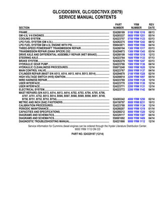
  • 2. 100 YRM 1316 Description General WARNING The lift truck must be put on blocks for some types of maintenance and repairs. The removal of the following assemblies will cause large changes in the center of gravity: mast, drive axle, engine and transmission, and counterweight. When the lift truck is put on blocks, put additional blocks in the following positions to maintain stability: • Before removing the mast and drive axle, put blocks under the counterweight so the lift truck cannot fall backward. • Before removing the counterweight, put blocks under the mast assembly so the lift truck cannot fall forward. The surface must be solid, even, and level when the lift truck is put on blocks. Make sure any blocks used to support the lift truck are solid, one-piece units. See the procedure How to Put Lift Truck on Blocks in the Operating Manual or the Periodic Maintenance section for your lift truck. If additional engine repairs are necessary for lift trucks covered in this manual see: • GM Engines, 4.3 Liter V-6 600 YRM 1251 • Kubota Diesel 3.8L Engines 600 YRM 1557 If additional transmission repairs are necessary for lift trucks covered in this manual see: • Powershift Transmission, Repair 1300 YRM 1129 • Powershift Transmission, Repair 1300 YRM 1529 • One and Two Speed Transmissions, Repair 1300 YRM 1569 • Three-Speed Powershift Transmission Repair 1300 YRM 1317 • Two-Speed Powershift Transmission Repair 1300 YRM 1343 This section contains the description of the frame (see Figure 1) and connected parts. Procedures for remov- ing and installing the counterweight, hood, overhead guard, engine and transmission, and exhaust system are found in this section. Checks for the operator re- straint system and procedures for the repair of tanks and installation of safety labels are also included. Description The frame is one weldment and includes the hydraulic tank and fuel tank for gasoline or diesel fuel. See Fig- ure 1. There is a counterweight for each capacity of lift truck. The counterweights are similar in appearance, but are different weights. See Table 2. The muffler is fastened to the frame inside the counter- weight. The overhead guard, cowl, and hood are installed on the frame. The hood is connected to the frame with hinges. Two gas-controlled springs provide assistance when raising the hood and hold the hood in the open po- sition. The floor plate and side covers can be removed for access to the engine, transmission, and other com- ponents. 1
  • 3. Description 100 YRM 1316 1. COWL PLATE 2. FENDERS 3. HOOD MOUNTS 4. COUNTERWEIGHT MOUNTS 5. HYDRAULIC TANK 6. FUEL TANK (GAS OR DIESEL) Figure 1. Frame 2
  • 4. 100 YRM 1316 Hood, Seat, Dash, and Side Covers Replacement Hood, Seat, Dash, and Side Covers Replacement REMOVE 1. Remove the floor mat and floor plate. See Figure 3. 2. Slide the seat to the closest position to the steering column. 3. Fully tilt the steering column forward. 4. If your truck is equipped with an LPG tank, swing the tank off to the side. Push in the bracket re- lease pin, swing the tank and bracket out to the side of the lift truck. If your truck is equipped with a swing-out and drop-down LPG tank bracket (EZ Tank Bracket), swing the tank down to the side of the truck for ease of removal. See one of the fol- lowing Service Manuals for procedures to swing the LPG tank to the side. LPG Fuel System, GM 4.3L Engine With GFI 900 YRM 1242 for lift truck models: • GLC/GDC60VX, GLC/GDC70VX (GC/GLC/ GDC135VX, GC/GLC/GDC155VX) (C879, D879) LPG Fuel System, GM 4.3L Engine With PSI 900 YRM 1556 for lift truck models: • GLC/GDC60VX, GLC/GDC70VX (GC/GLC/ GDC135VX, GC/GLC/GDC155VX) (D879, E879, F879) 5. Raise the hood latch, unlatch and lift up the hood. See Figure 2. 6. Remove the two capscrews holding the left and right rear side panel to the frame. Remove the rear side panel from the frame. See Figure 3. 3
  • 5. Hood, Seat, Dash, and Side Covers Replacement 100 YRM 1316 NOTE: SWIVEL SEAT AND VENTED HOOD ARE OPTIONAL FEATURES. A. SIDE VIEW OF HOOD AND SEAT B. SIDE VIEW OF HOOD C. BOTTOM VIEW OF HOOD D. 3-D VIEW OF VENTED HOOD WITH SWIVEL SEAT 1. SEAT 2. HOOD 3. FRAME 4. SEAT WIRE HARNESS 5. SEAT WIRE HARNESS CONNECTOR 6. CABLE CLIPS 7. HINGE SCREWS 8. GAS SPRING 9. ATTACHMENT HOLES ATTACHING HOOD TO SEAT (SEMI-SUSPENSION) 10. SEAT WIRE HARNESS BRACKETS 11. SEAT LINER 12. HOOD LATCH 13. ATTACHMENT HOLES ATTACHING HOOD TO SEAT (NON-SUSPENSION) 14. ATTACHMENT HOLES ATTACHING HOOD TO SEAT (FULL SUSPENSION) 15. SPACER 16. FLANGE NUTS Figure 2. Hood and Seat Arrangement 4
  • 6. 100 YRM 1316 Hood, Seat, Dash, and Side Covers Replacement 1. DEBRIS COVER 2. COUNTERWEIGHT COVER 3. RADIATOR COVER 4. LEFT SIDE REAR PANEL (GAS AND DIESEL SHOWN) 5. RIGHT SIDE REAR PANEL 6. UPPER STEERING COLUMN COVER 7. LOWER STEERING COLUMN COVER 8. SEAL 9. FLOOR MAT 10. FLOOR PLATE 11. SPLASH SHIELD (GAS AND DIESEL) 12. CAPSCREW 13. FOLD OVER NUT 14. SEAL PLATE ASSEMBLY 15. RIGHT SIDE FRONT FENDER COVER 16. RIGHT SIDE STEP PLATE 17. RIGHT SIDE STEP PLATE 18. DASH ASSEMBLY 19. KICK PANEL Figure 3. Side Covers, Floor Plate, and Cowl Components 5
  • 7. Hood, Seat, Dash, and Side Covers Replacement 100 YRM 1316 7. Remove the two capscrews holding the left and right fender covers to the front overhead guard leg. Remove covers. See Figure 3. 8. Remove the four capscrews holding the left and right front side panels to the frame. Remove pan- els. 9. Fully lower the steering column. 10. Remove upper steering column cover by pulling up on upper steering column cover to release the latches (one on either side), and pulling cover away from steering column. See Figure 4. 11. Remove the five fasteners (see Figure 4) securing the dash to the top of the cowl. Remove the four clips, located underneath dash, that attach the dash to the kick panel. Lift to remove the dash. 12. Lift the kick panel to remove it from the truck. See Figure 3. 13. Remove the three capscrews holding the seal plate. Remove seal plate. See Figure 5. 14. Disconnect the seat wire harness connector. See Figure 2. CAUTION When removing the seat from the hood, do not use an impact wrench to remove the capscrews. Dam- age can be caused to the threads on the screws and in the holes. 15. If the seat is to be removed, and truck is equipped with a non-swivel seat, remove the seat wire har- ness from the seat wire harness brackets that are attached to the underside of the hood. Remove the cable clips from the seat wire harness. If truck is equipped with a swivel seat, remove seat wire har- ness from seat wire harness bracket attached to the underside of the hood and behind the seat. See Figure 2. 16. Remove the four flange nuts holding the seat to the hood. Lift the seat off the hood. Pull the seat wire harness through the hood. See Figure 2. 17. Remove the capscrews and washers at the top of the gas springs. Remove gas springs from the hood. See Figure 2. 18. Remove the hinge screws, located in the rear of the hood. 19. Lift the hood from the truck. See Figure 2. INSTALL 1. Place the hood onto the lift truck frame. 2. Install the hinge screws, located in the rear of the hood, and tighten to 38 N•m (28 lbf ft). See Fig- ure 2. 3. Align the holes in the gas springs with holes in the hood. There are two sets of holes used to install the gas springs to the hood, based on the type of seat the installed on the lift truck. One set is for installing the cylinder end of the gas springs and the other set is for attaching the rod end of the gas springs. Install capscrews and washers to at- tach gas springs to the hood. Refer to Figure 6 and Table 1 for correct holes used to connect the rod end of the cylinder, depending on the type of seat installed on the lift truck. Tighten capscrews to 19.2 N•m (170 lbf in). 6
  • 8. 100 YRM 1316 Hood, Seat, Dash, and Side Covers Replacement NOTE: TOP VIEW OF DASH SHOWN. A. INDICATES TO PULL UP TO UNLATCH 1. ALLEN SCREWS 2. COWL 3. UPPER STEERING COLUMN COVER 4. LOWER STEERING COLUMN COVER Figure 4. Remove Dash From Cowl 7
  • 9. Hood, Seat, Dash, and Side Covers Replacement 100 YRM 1316 1. CAPSCREWS 2. SEAL PLATE Figure 5. Remove Seal Plate From Dash 8
  • 10. 100 YRM 1316 Hood, Seat, Dash, and Side Covers Replacement NOTE: SEE TABLE 1 FOR HOLES TO USE TO ATTACH ROD END OF GAS SPRING. A. LEFT SIDE B. RIGHT SIDE C. FULL SUSPENSION SEAT D. NON-SUSPENSION SEAT 1. MOUNTING LOCATION FOR CYLINDER END OF GAS SPRING FOR NON-SUSPENSION SEAT 2. MOUNTING LOCATION FOR CYLINDER END OF GAS SPRING FOR SEMI OR FULL SUSPENSION SEAT Figure 6. Gas Spring Installation 9
  • 11. Hood, Seat, Dash, and Side Covers Replacement 100 YRM 1316 Table 1. Gas Spring Installation, Holes for Installing Rod Ends (See Figure 6) Full or Semi Suspension Seat Non-Suspension SeatCounterweight Type Left Side Right Side Left Side Right Side Standard Counterweight 2 2 1 1 4. Install latch striker in highest slot position. Check that latch striker is in center of jaws of hood latch when hood closes. Open and close the hood to en- sure that the center pin strikes the hood latch prop- erly and that the stop screw contacts the frame. A properly closed hood MUST click twice on the hood latch. If the hood latch does not close properly, loosen the capscrews on the back of the center pin and adjust the center pin up or down as required for correct alignment. See Figure 7. 5. Push down until hood just touches rubber bumper. Make sure latch striker is still in center of hood latch. Open hood and tighten capscrews for latch. CAUTION When installing the seat to the hood, do not use an impact wrench to install the capscrews. Damage can be caused to the threads on the screws and in the holes. 6. Place the seat on the hood and thread the seat wire harness through the hole in the hood. See Figure 2. 7. Align the holes in the seat with the holes in the hood. Insert washers and capscrews. Tighten cap- screws to 18 N•m (159 lbf in). 8. If truck is equipped with a non-swivel seat, tie cable clips to seat wire harness and insert harness into seat wire harness brackets under hood. If truck is equipped with a swivel seat, secure seat harness to bracket. See Figure 2. 9. Check operation of hood latch. Have an opera- tor sit in the seat. Make sure hood is fully closed (two clicks). Also check that hood touches rubber bumper. If necessary, repeat Step 5. 10. Using three capscrews, Install seal plate. See Fig- ure 5. 11. Install kick panel onto truck. See Figure 3. 12. Install dash and allen screws to top of cowl. See Figure 4. Tighten capscrews to 0.5 to 0.6 N•m (5 to 6 lbf in). 13. Install four clips to attach the dash to kick panel. See Figure 4. 10
  • 12. 100 YRM 1316 Hood, Seat, Dash, and Side Covers Replacement 14. Install upper and lower steering column covers by connecting the two covers together and pressing each side until latched. 15. Using four capscrews, install the left and right front side panels to frame. See Figure 3. 16. Using two capscrews install the left and right fender covers to front of overhead guard legs. 17. Using two capscrews, install the left and right rear side covers to frame. See Figure 3. 18. Install the floor mat and floor plate. 19. If truck is equipped with an LPG tank, swing LPG tank into position on back of counterweight. See one of the following Service Manuals for procedures to swing the LPG tank onto the coun- terweight. LPG Fuel System, GM 4.3L Engine With GFI 900 YRM 1242 for lift truck models: • GLC/GDC60VX, GLC/GDC70VX (GC/GLC/ GDC135VX, GC/GLC/GDC155VX) (C879, D879) LPG Fuel System, GM 4.3L Engine With PSI 900 YRM 1556 for lift truck models: • GLC/GDC60VX, GLC/GDC70VX (GC/GLC/ GDC135VX, GC/GLC/GDC155VX) (D879, E879, F879) 20. Adjust the steering column and seat positions. 1. HOOD 2. HOOD LATCH 3. CENTER PIN 4. CAPSCREW Figure 7. Hood Latch Adjustment 11
  • 13. Steering Column 100 YRM 1316 Steering Column DESCRIPTION This section describes the repair procedures for the steering column. The steering column assembly mounts to the cowl inside the operator compartment and is the mechanical connection between the steering wheel and the steering control unit. The steering col- umn includes the steering wheel, housing, bracket and lower shaft. For lift trucks with gas and LPG engines, bolts and bushings attach the steering column to the cowl standoffs. For lift trucks with diesel engines, bolts, bushings and isolators attach the steering column to the cowl standoffs. See Figure 8. STEERING COLUMN REPAIR Remove 1. Put blocks on each side (front and back) of tires to prevent lift truck from moving. WARNING Disconnect the battery before removing any covers to avoid injury to personnel. 2. Attach a tag on battery connector or negative bat- tery cable stating, DO NOT CONNECT BATTERY. Move steering column to most FORWARD position. CAUTION If a puller tool is used to remove steering wheel from steering column, be careful not to damage horn wires. NOTE: This procedure is for removal of all components of steering column assembly. Not all components are removed for a repair procedure. Do only those steps of procedure necessary to remove required component. NOTE: Tag wires prior to disconnect. 3. Remove horn button assembly and disconnect electrical wires. Remove large hex nut and steer- ing wheel from steering column. See Figure 9. 4. Remove steering column covers. Remove floor mats and floor plate. See section Hood, Seat, Dash, and Side Covers Replacement. NOTE: Perform Step 5 for lift trucks equipped with gas or LPG engines. 5. Remove four capscrews, four bushings and steer- ing column from cowl standoffs. See Figure 10. NOTE: Perform Step 6 for lift trucks equipped with diesel engines. 6. Remove four capscrews, four bushings, four isola- tors, steering column and four isolators from cowl standoffs. See Figure 10. Disassemble NOTE: Remove and discard snap rings if installed. 1. Remove two pins and gas spring from housing. See Figure 11, for lift trucks manufactured before January, 2012. See Figure 12, for lift trucks manufactured after Jan- uary, 2012. 2. Remove two pivot bolts, two bushings, two nuts and bracket from housing. See Figure 11, for lift trucks manufactured before January, 2012. See Figure 12, for lift trucks manufactured after Jan- uary, 2012. 3. Remove split pin and lower shaft from upper shaft. See Figure 11, for lift trucks manufactured before January, 2012. See Figure 12, for lift trucks manufactured after Jan- uary, 2012. 4. Remove connector from connector bracket. Re- move connector bracket, fastener, four screws and two horn contacts from housing. See Figure 11, for lift trucks manufactured before January, 2012. See Figure 12, for lift trucks manufactured after Jan- uary, 2012. 12
  • 14. 100 YRM 1316 Steering Column NOTE: DIESEL SHOWN, LPG AND GAS SIMILAR. 1. STEERING WHEEL 2. STEERING COLUMN 3. COWL Figure 8. Steering Column and Cowl 1. HORN BUTTON 2. HEX NUT 3. STEERING WHEEL 4. STEERING COLUMN Figure 9. Steering Wheel Remove/Install NOTE: DIESEL SHOWN, LPG AND GAS SIMILAR. 1. CAPSCREW 2. BUSHING 3. ISOLATOR 4. STEERING COLUMN 5. COWL STANDOFF Figure 10. Steering Column Remove/Install 13
  • 15. Steering Column 100 YRM 1316 Figure 11. Steering Column Assembly, Lift Trucks Manufactured Before January, 2012 14
  • 16. 100 YRM 1316 Steering Column Legend for Figure 11 1. PIN 2. LOWER SHAFT 3. SPLIT PIN 4. UPPER SHAFT 5. HOUSING 6. HORN CONTACT 7. SCREW 8. FASTENER 9. CONNECTOR BRACKET 10. PIVOT BOLT 11. BUSHING 12. NUT 13. GAS SPRING 14. BRACKET 15. CONNECTOR 15
  • 17. Steering Column 100 YRM 1316 1. BRACKET 2. SPACER 3. JOINT 4. NUT 5. WASHER 6. SCREW 7. UPPER SHAFT 8. HOUSING 9. PIN 10. LOWER SHAFT 11. GAS SPRING 12. BOLT 13. BUSHING 14. CONNECTOR 15. FASTENER 16. HORN CONTACT Figure 12. Steering Column Assembly, Lift Trucks Manufactured After January, 2012 Clean WARNING Cleaning solvents can be flammable and toxic and can cause skin irritation. When using cleaning solvents, always follow the solvent manufacturer’s recommended safety precautions. WARNING Compressed air is used for cleaning and drying pur- poses, or for cleaning restrictions. Wear protective clothing (goggles/shields, gloves, etc.). Make sure the path of the compressed air is away from all per- sonnel to avoid injury. 1. Clean metal parts in solvent. Remove all traces of old lubricant and dirt. Clean nonmetal parts with warm soapy water and a lint free cloth. 2. After cleaning, dry parts with compressed air. DO NOT dry parts with a cloth. Inspect 1. Inspect for loose, burned, missing, cracked or dam- aged hardware. 2. Inspect all parts for dents, holes, bends, burrs, rust, corrosion or marred finishes. 3. Replace all defective or damaged parts. 16
  • 18. 100 YRM 1316 LPG Tank and Bracket Replacement Assemble NOTE: This procedure is for installation of all compo- nents of steering column assembly. Not all components are removed for a repair procedure. Do only those steps of procedure necessary to install required component. NOTE: Perform Step 1 only for lift trucks manufactured before January, 2012. 1. Lubricate horn contact slip rings with a small amount of conductive grease (Yale P/N 582014302). 2. Install fastener, connector bracket and connector, two horn contacts and four screws. See Figure 11, for lift trucks manufactured before January 2012. See Figure 12, for lift trucks manufactured after Jan- uary 2012. 3. Assemble lower shaft and upper shaft, secure with spit pin. See Figure 11, for lift trucks manufactured before January 2012. See Figure 12, for lift trucks manufactured after Jan- uary 2012. 4. Install two pivot bolts, two bushings, two nuts and bracket onto housing. See Figure 11, for lift trucks manufactured before January 2012. See Figure 12, for lift trucks manufactured after Jan- uary 2012. 5. Install gas spring and two pins on housing. See Figure 11, for lift trucks manufactured before January 2012. See Figure 12, for lift trucks manufactured after Jan- uary 2012. Install NOTE: Lubricate spline end of lower shaft with multi purpose grease, see Periodic Maintenance Manual for your lift truck. NOTE: Perform Step 1 for lift trucks equipped with gas or LPG engines. 1. Install steering column, four bushings and four bolts on cowl standoffs. Tighten bolts to 38 N•m (28 lbf ft). See Figure 10. NOTE: Perform Step 2 for lift trucks equipped with diesel engines. 2. Install four isolators, steering column, four isola- tors, four bushings, and four bolts on cowl standoffs. Tighten bolts to 38 N•m (28 lbf ft). See Figure 10. 3. Install floor plate, floor mats, and steering column covers. See section Hood, Seat, Dash, and Side Covers Replacement. 4. Install steering wheel and hex nut on steering col- umn, tighten hex nut to 40 to 54 N•m (30 to 40 lbf ft). Connect electrical wiring and install horn button. See Figure 9. 5. Remove tag from negative battery connector and connect to battery. Adjust steering column to neu- tral position. 6. Remove blocks from each side of tires. LPG Tank and Bracket Replacement For procedures to remove and install the LPG tank, LPG tank bracket, and the LPG tank alignment pin, see one of the following Service Manuals. LPG Fuel System, GM 4.3L Engine With PSI 900 YRM 1556 for lift truck models • GLC40, 45, 55VX; GLC55SVX; (GLC080, 100, 120VX; GLC080, 100VXBCS; GLC120SVX; GLC120VXPRS) (E818, F818) • GLP40VX5/VX6; GLP45SVX5, GLP45VX6; GLP50- 55VX (GLP080, 90, 100, 110, 120VX) (G813, H813, J813) LPG Fuel System, GM 4.3L Engine With GFI 900 YRM 1242 for lift truck models • GLC60VX, GLC70VX (GLC135VX, GLC155VX) (C879, D879) LPG Fuel System, GM 4.3L Engine With PSI 900 YRM 1556 for lift truck models • GLC60VX, GLC70VX (GLC135VX, GLC155VX) (D879, E879, F879) 17
  • 19. Counterweight Replacement 100 YRM 1316 Counterweight Replacement REMOVE WARNING The lift truck must be put on blocks for some types of maintenance and repair. The removal of the following assemblies will cause large changes in the center of gravity: mast, drive axle, engine and transmission, and counterweight. When the lift truck is put on blocks, put additional blocks in the following positions to maintain stability: • Before removing the mast and drive axle, put blocks under the counterweight so the lift truck cannot fall backward. • Before removing the counterweight, put blocks under the mast assembly so the lift truck cannot fall forward. The surface must be solid, even, and level when the lift truck is put on blocks. Make sure that any blocks used to support the lift truck are solid, one- piece units. See the procedure How to Put Lift Truck on Blocks in the Operating Manual or the Periodic Maintenance section for your lift truck. WARNING DO NOT operate the lift truck if the capscrew for the counterweight is not installed. When the capscrew is removed, the counterweight can fall from the lift truck. WARNING LPG can cause an explosion. DO NOT cause sparks or permit flammable material near the LPG system. LPG fuel systems can be disconnected indoors only if the lift truck is at least 8 m (26 ft) from any open flame, motor vehicles, electrical equipment, or ignition source. Close the shutoff valve on the LPG tank before any part of the engine fuel system is disconnected. Run the engine until the fuel in the system is used and the engine stops. If the engine will not run, close the shutoff valve on the LPG tank. Loosen the fitting on the supply hose from the LPG tank where it enters the filter unit. Permit the pressure in the fuel system to decrease slowly. Fuel leaving the fitting removes heat. Use a cloth to protect your hands from the cold fitting. NOTE: The counterweight is held in position on frame by two hooks that are part of frame. One M30 x 3.5 x 120 capscrew holds counterweight to lower part of frame. See Figure 13. NOTE: If lift truck is equipped with an overhead exhaust system, remove overhead exhaust pipe before remov- ing counterweight. See section Exhaust System Repair for procedures. 1. If lift truck has an LPG fuel system, see one of the following Service Manuals to remove the LPG tank and bracket so that the counterweight can be re- moved. LPG Fuel System, GM 4.3L Engine With GFI 900 YRM 1242 for lift truck models • GLC60VX, GLC70VX (GLC135VX, GLC155VX) (C879, D879) LPG Fuel System, GM 4.3L Engine With PSI 900 YRM 1556 for lift truck models • GLC60VX, GLC70VX (GLC135VX, GLC155VX) (D879, E879, F879) WARNING The counterweight is heavy. Make sure that the eye- bolt and lifting devices have enough capacity to lift the weight. The approximate weights of the coun- terweight castings are shown in Table 2. 2. Install a lifting eye in lift hole of counterweight. See Figure 13. Connect a crane to lifting eye and raise crane until it holds part of weight of counterweight. Remove tow pin and remove capscrew that holds counterweight to frame. See Figure 13. Use crane to lift counterweight from lift truck. Put counter- weight on floor so that it has stability and will not fall over. Take care not to damage exhaust or cool- ing components. INSTALL 1. Make sure seals are on counterweight. See Fig- ure 14. 2. Use a crane to install counterweight on lift truck. When counterweight is installed, make sure hooks on frame fully engage counterweight so it is aligned with parts of frame. Install and tighten capscrew to 1020 N•m (750 lbf ft). 18
  • 20. 100 YRM 1316 Counterweight Replacement 3. Install tow pin and roll pin, if equipped. See section Tow Pin for procedures. 4. If lift truck has an LPG fuel system, see one of the following Service Manuals to install LPG tank and bracket, after counterweight has been installed. LPG Fuel System, GM 4.3L Engine With GFI 900 YRM 1242 for lift truck models • GLC60VX, GLC70VX (GLC135VX, GLC155VX) (C879, D879) LPG Fuel System, GM 4.3L Engine With PSI 900 YRM 1556 for lift truck models • GLC60VX, GLC70VX (GLC135VX, GLC155VX) (D879, E879, F879) 5. If lift truck is equipped with an overhead exhaust system, install overhead exhaust pipe. See section Exhaust System Repair for procedures. TOW PIN Remove and Install 1. Remove tow pin from counterweight by driving roll pin out. See Figure 15. 2. Install tow pin into counterweight and install roll pin. Remove and Install For Lift Truck ModelsGLC55SVX (GC/GLC80XVBCS, GC/GLC100VXBCS; GC/GLC120SVX; and GC/GLC120VXPRS) (E818, F818) and GLP/GDP40VX5/VX6; GLP/GDP45SVX5, GLP/GDP45VX6; GLP/GDP50-55VX (GP/GLP/GDP080, 090, 100, 110, 120VX) (J813) 1. Remove tow pin from counterweight by grasping wire and pulling tow pin from counterweight. See Figure 16. 2. Install tow pin into counterweight dropping tow pin into counterweight. 1. FRAME HOOK 2. SEALS 3. CAPSCREW 4. COUNTERWEIGHT COVER 5. COUNTERWEIGHT 6. TOW PIN 7. ROLL PIN 8. WASHER Figure 13. Counterweight Installation Table 2. Weight of Counterweights Model Weight GLC/GDC60VX GLC/GDC70VX GC/GLC/GDC135VX GC/GLC/GDC155VX (C879, D879, E879, F879) 2779 kg (6126 lb) 19
  • 21. Counterweight Replacement 100 YRM 1316 1. CAPSCREW 2. COUNTERWEIGHT COVER 3. COUNTERWEIGHT 4. TOW PIN 5. ROLL PIN 6. WASHER 7. SEALS Figure 14. Counterweight Components 20
  • 22. 100 YRM 1316 Counterweight Replacement 1. TOW PIN 2. ROLL PIN Figure 15. Tow Pin 1. WIRE 2. TOW PIN Figure 16. Tow Pin 21
  • 23. Overhead Guard Replacement 100 YRM 1316 Overhead Guard Replacement REMOVE WARNING DO NOT operate the lift truck without the overhead guard correctly fastened to the lift truck. WARNING DO NOT weld mounts for lights or accessories to legs of the overhead guard. Changes that are made by welding, or by drilling holes that are too big or in the wrong location, can reduce the strength of the overhead guard. See your dealer for Yale lift trucks BEFORE perform- ing any changes to the overhead guard. NOTE: The lift trucks covered in this YRM are equipped with either a high or low overhead guard. The removal and installation procedures for both types of overhead guards are the same. No welding or drilling on legs of overhead guard is per- mitted as per previous WARNING. NOTE: The lifting device can be connected to any num- ber of positions on overhead guard depending upon lift- ing device available. The ideal choices are a four point sling connected to all four corners on top of overhead guard, or a two point sling connected to two opposite corners of overhead guard. If a single point hoist is used, make sure that lift point is in center of overhead guard. If during initial start of lift, the overhead guard is off balance, lower immediately and move hoist to a more centered point. 1. Connect a lifting device to remove overhead guard. Loosen clamp and disconnect air intake hose from elbow. Remove bolts, elbow, retainer, and grommet from overhead guard rear leg. See Figure 17. NOTE: Perform Step 2 for lift truck models GLC/ GDC60VX, GLC/GDC70VX (GC/GLC/GDC135VX, GC/GLC/GDC155VX) (F879) equipped with Diesel Particulate Filter (DPF). 2. Disconnect wires from back of DPF display. See Figure 19. 3. Disconnect wires between frame and overhead guard. When overhead guard is lifted from frame, make sure that electrical wires are moved through holes in overhead guard so that they are not dam- aged. NOTE: Perform Step 4 for lift truck models GLC/ GDC60VX, GLC/GDC70VX (GC/GLC/GDC135VX, GC/GLC/GDC155VX) (C879, D879, E879). 4. The rear legs of overhead guard have two cap- screws that are located under hood inside engine compartment, next to radiator. Remove capscrews. See Figure 18. NOTE: Perform Step 5 for lift truck models GLC/ GDC60VX, GLC/GDC70VX (GC/GLC/GDC135VX, GC/GLC/GDC155VX) (F879). 5. The rear legs of overhead guard have three cap- screws and a nut that are located under hood in- side engine compartment, next to radiator. Remove capscrews and nuts. See Figure 19. 6. Remove fender cover, dash, and kick panel to remove two capscrews on front legs of overhead guard. See Hood, Seat, Dash, and Side Covers Replacement for removal procedures. 7. Using a lifting device, remove overhead guard from frame and place on floor. 22
  • 24. 100 YRM 1316 Overhead Guard Replacement INSTALL 1. Connect lifting device to top of overhead guard. In- stall overhead guard in position on lift truck. 2. Install two capscrews on front legs of overhead guard. Tighten capscrews to 66 N•m (49 lbf ft). See Figure 18. NOTE: Perform Step 3 for lift truck models GLC/ GDC60VX, GLC/GDC70VX (GC/GLC/GDC135VX, GC/GLC/GDC155VX) (F879) equipped with Diesel Particulate Filter (DPF). 3. Connect wires to back of DPF display. See Fig- ure 19. 4. Install fender cover, dash, and kick panel. See Hood, Seat, Dash, and Side Covers Replacement for installation procedures. 5. Install two capscrews on rear legs of overhead guard. Tighten capscrews to 66 N•m (49 lbf ft). See Figure 18. NOTE: Perform Step 6 for lift truck models GLC/ GDC60VX, GLC/GDC70VX (GC/GLC/GDC135VX, GC/GLC/GDC155VX) (F879). 6. Install three capscrews and nut on rear legs of overhead guard. Tighten capscrews to 66 N•m (49 lbf ft). See Figure 19. 7. Connect air intake hose by installing bolts, elbow, retainer, and grommet to overhead guard rear leg. See Figure 17. LED TAIL, BACKUP, AND BRAKE LIGHTS, REPLACE These light assemblies are nonrepairable and must be replaced as an assembly. See section Electrical Sys- tem 2200 YRM 1142 for procedures to replace these lights. 1. CLAMP 2. AIR INTAKE HOSE 3. BOLTS 4. ELBOW 5. RETAINER 6. GROMMET Figure 17. Disconnect Air Intake Hose 23
  • 25. Overhead Guard Replacement 100 YRM 1316 1. CAPSCREWS - FRONT LEGS 2. HANDLE 3. CAPSCREWS - REAR LEGS 4. FRAME Figure 18. Overhead Guard 1. CAPSCREWS - FRONT LEGS 2. HANDLE 3. CAPSCREWS - REAR LEGS 4. FRAME 5. DPF DISPLAY 6. NUT Figure 19. Overhead Guard 24
  • 26. 100 YRM 1316 Operator Restraint System Replacement Operator Restraint System Replacement DESCRIPTION The seat belt, hip restraint brackets, seat and mount- ing, hood, and latches are all part of operator restraint system. Each item must be checked to make sure it is attached securely, functions correctly, and is in good condition. See Figure 20. The seat belt, when properly buckled across operator, will permit slight operator repositioning without activat- ing locking mechanism. If truck tips, travels off a dock, or comes to a sudden stop, locking mechanism will be activated and hold the operator’s lower torso in seat. A seat belt that is damaged, worn or does not operate properly will not provide protection when it is needed. The end of belt must fasten correctly in latch. The seat belt must be in good condition. Replace seat belt if damage or wear is seen. See Figure 20. The following seat belt operation checks must be per- formed: • With hood closed and in locked position, pull seat belt slowly from retractor assembly. Make sure seat belt pulls out and retracts smoothly. If seat belt does not pull out of retractor assembly, internal latch may be locked. Pull firmly on seat belt and hold for a mo- ment to remove slack from belt in retractor. Release seat belt. Seat belt will retract and internal latch will unlock. If seat belt cannot be pulled from retractor assembly or belt will not retract, replace seat belt as- sembly. • With hood closed and in locked position, pull seat belt with a sudden jerk. Make sure seat belt will not pull from retractor assembly. If seat belt can be pulled from retractor, when it is pulled with a sudden jerk, replace seat belt assembly. • With hood in open position, make sure seat belt will not pull from retractor assembly. If seat belt can be pulled from retractor, with hood in open position, re- place seat belt assembly. Make sure seat rails and latch striker are not loose. The seat rails must lock tightly in position, but move freely when unlocked. The seat rails must be correctly fas- tened to hood and hood fastened to hinges on frame. The hood must be fully closed. Attempt to lift hood to make sure it is closed. Adjust hood, hood latch, and latch striker when any of parts of operator restraint system are installed or re- placed. See section Hood, Seat, Dash, and Side Cov- ers Replacement in this manual for adjustment proce- dures for hood. 25
  • 27. Operator Restraint System Replacement 100 YRM 1316 1. WEIGHT ADJUSTMENT LEVER 2. HIP RESTRAINT 3. SEAT BELT LATCH 4. SEAT 5. HOOD 6. SEAT RAIL 7. SPACER Figure 20. Operator Restraint System 26
  • 28. 100 YRM 1316 Engine Replacement Engine Replacement REMOVE ENGINE ONLY WARNING The lift truck must be put on blocks for some types of maintenance and repairs. The removal of the following assemblies will cause large changes in the center of gravity: mast, drive axle, engine and transmission, and counterweight. When the lift truck is put on blocks, put additional blocks in the following positions to maintain stability: • Before removing the mast and drive axle, put blocks under the counterweight so the lift truck cannot fall backward. • Before removing the counterweight, put blocks under the mast assembly so the lift truck cannot fall forward. The surface must be solid, even, and level when the lift truck is put on blocks. Make sure that any blocks used to support the lift truck are solid, one- piece units. See the procedure How to Put Lift Truck on Blocks in the Operating Manual or the Periodic Maintenance section for your lift truck. The engine can be removed with or without transmis- sion. Follow procedures below to remove engine with- out transmission. See Figure 21. WARNING Always disconnect the cables at the battery before you make repairs to the engine. Disconnect the ca- ble at the negative terminal first. WARNING LPG can cause an explosion. DO NOT cause sparks or permit flammable material near the LPG system. LPG fuel systems can be disconnected indoors only if the lift truck is at least 8 m (26 ft) from any open flame, motor vehicles, electrical equipments, or ignition source. 1. For lift trucks equipped with an LPG fuel system, close shutoff valve on tank and run engine until all fuel is gone and engine stops. 2. If lift truck is equipped with an LPG fuel tank, swing tank to side. See one of the following Service Man- uals: LPG Fuel System, GM 4.3L Engine With GFI 900 YRM 1242 for lift truck models • GLC60VX, GLC70VX (GLC135VX, GLC155VX) (C879, D879) LPG Fuel System, GM 4.3L Engine With PSI 900 YRM 1556 for lift truck models • GLC60VX, GLC70VX (GLC135VX, GLC155VX) (D879, E879, F879) 3. Remove floor mat and floor plate. WARNING DO NOT remove the radiator cap from the radiator when the engine is hot. When the radiator cap is removed, the pressure is released from the system. If the system is hot, the steam and boiling coolant can cause burns. 4. Let coolant cool to ambient temperature. Place a drain pan with a capacity greater than capacity of cooling system under radiator. Remove radiator cap. CAUTION Disposal of lubricants and fluids must meet local environmental regulations. 5. Open drain plug or loosen hose clamp and discon- nect bottom radiator hose to drain coolant from ra- diator and engine. See Figure 22 and Figure 23 for lift trucks equipped with GM 4.3L engine. See Figure 24 for lift truck models equipped with Cummins QSB 3.3L diesel engine. See Figure 25 and Figure 26 for lift truck models equipped with Kubota 3.8L diesel engine. See Figure 27 for lift truck models equipped with Cummins 4.5L diesel engine. 27
  • 29. Engine Replacement 100 YRM 1316 Figure 21. Engine and Transmission Mounting Arrangement 28
  • 30. 100 YRM 1316 Engine Replacement Legend for Figure 21 NOTE: PART OF FRAME NOT SHOWN FOR CLARITY. A. GM 4.3L ENGINE B. CUMMINS 4.5L DIESEL ENGINE C. CUMMINS QSB 3.3L DIESEL ENGINE D. KUBOTA 3.8L DIESEL ENGINE 1. TRANSMISSION ISOLATOR ASSEMBLY 2. TRANSMISSION MOUNTING BRACKET 3. ENGINE MOUNTING BRACKET 4. ENGINE CROSSMEMBER 5. ENGINE ISOLATOR ASSEMBLY 6. FRAME 7. ENGINE HARNESS CONNECTOR 8. LEFT CHASSIS WIRING HARNESS CONNECTOR 29
  • 31. Engine Replacement 100 YRM 1316 Figure 22. GM 4.3L LPG Engine with GFI and Transmission 30
  • 32. 100 YRM 1316 Engine Replacement Legend for Figure 22 NOTE: GFI FUEL SYSTEM SHOWN. PSI FUEL SYSTEM IS SIMILAR. NOTE: GM 4.3L GASOLINE ENGINE IS SIMILAR. A. TOP VIEW B. LEFT SIDE VIEW 1. BOTTOM RADIATOR HOSE 2. AIR FILTER HOSE 3. AIR FILTER AND BRACKET ASSEMBLY 4. LEFT HAND CHASSIS HARNESS CONNECTOR 5. ENGINE HARNESS CONNECTOR 6. LPG REGULATOR CONNECTOR 7. RIGHT HAND CHASSIS HARNESS 8. ELECTRONIC CONTROL MODULE (ECM) 9. POWER DISTRIBUTION MODULE (PDM) 10. BATTERY AND BATTERY TRAY 11. COOLANT HOSES 12. FAN PULLEY AND FAN SPACER 13. FAN 14. SHROUD 15. EXHAUST PIPE TO EXHAUST MANIFOLD 16. FUEL LINES 17. LEFT SIDE ENGINE MOUNT 18. STARTER MOTOR 19. CAPSCREWS 20. BELL HOUSING 21. RADIATOR CAP 22. OUTPUT YOKE 23. TRANSMISSION MOUNT 24. FLANGE NUT 25. WASHERS 26. ISOLATORS 27. BRAKE COOLING LINES 28. BATTERY CABLE (POSITIVE) 29. BATTERY CABLE (NEGATIVE) 31
  • 33. Engine Replacement 100 YRM 1316 Figure 23. GM 4.3L LPG Engine with PSI and Transmission 32
  • 34. 100 YRM 1316 Engine Replacement Legend for Figure 23 NOTE: GM 4.3L GASOLINE ENGINE IS SIMILAR. A. TOP VIEW B. LEFT SIDE VIEW 1. BOTTOM RADIATOR HOSE 2. AIR FILTER HOSE 3. AIR FILTER AND BRACKET ASSEMBLY 4. LEFT HAND CHASSIS HARNESS CONNECTOR 5. ENGINE HARNESS CONNECTOR 6. FUEL SENDING UNIT 7. RIGHT HAND CHASSIS HARNESS 8. ELECTRONIC CONTROL MODULE (ECM) 9. POWER DISTRIBUTION MODULE (PDM) 10. BATTERY AND BATTERY TRAY 11. COOLANT HOSES 12. FAN PULLEY AND FAN SPACER 13. FAN 14. SHROUD 15. EXHAUST PIPE TO EXHAUST MANIFOLD 16. FUEL LINES 17. LEFT SIDE ENGINE MOUNT 18. STARTER MOTOR 19. CAPSCREWS 20. BELL HOUSING 21. RADIATOR CAP 22. OUTPUT YOKE 23. TRANSMISSION MOUNT 24. FLANGE NUT 25. WASHERS 26. ISOLATORS 27. BRAKE COOLING LINES 28. BATTERY CABLE (POSITIVE) 29. BATTERY CABLE (NEGATIVE) 33
  • 35. Engine Replacement 100 YRM 1316 Figure 24. Cummins QSB 3.3L Diesel Engine and Transmission 34
  • 36. 100 YRM 1316 Engine Replacement Legend for Figure 24 A. TOP VIEW B. LEFT SIDE VIEW 1. RADIATOR CAP 2. SHROUD 3. BOTTOM COOLANT HOSE 4. AIR FILTER HOSE 5. AIR FILTER AND BRACKET 6. EXHAUST PIPE TO EXHAUST MANIFOLD 7. ENGINE MOUNTING BRACKETS 8. FUEL LINES 9. ENGINE HARNESS CONNECTOR 10. BRAKE COOLING LINE 11. HYDRAULIC SUPPLY LINE 12. TRANSMISSION MOUNTING BRACKET 13. ELECTRONIC CONTROL MODULE 14. RIGHT HAND ENGINE HARNESS 15. HYDRAULIC RETURN LINE 16. BATTERY AND BATTERY TRAY 17. BATTERY CABLE (POSITIVE) 18. BATTERY CABLE (NEGATIVE) 19. FAN SPACER AND FAN PULLEY 20. CHARGE AIR HOSE 35
  • 37. Engine Replacement 100 YRM 1316 Figure 25. Kubota 3.8L Engine and Transmission for Lift Truck Model GLC/GDC60VX, GLC/GDC70VX (GC/GLC/GDC135VX, GC/GLC/GDC155VX) (E879) 36
  • 38. 100 YRM 1316 Engine Replacement Legend for Figure 25 A. TOP VIEW B. SIDE VIEW 1. SHROUD 2. RADIATOR CAP 3. BATTERY CABLE (NEGATIVE) 4. BATTERY AND BATTERY TRAY 5. BATTERY CABLE (POSITIVE) 6. TRANSMISSION COOLING HOSE 7. HYDRAULIC SUPPLY LINE 8. TRANSMISSION MOUNTING BRACKET 9. BRAKE COOLING LINE 10. ENGINE HARNESS CONNECTOR 11. AIR FILTER AND BRACKET 12. AIR FILTER HOSE 13. FAN, SPACER, AND FAN PULLEY 14. BOTTOM COOLANT HOSE 15. ENGINE MOUNTS 16. EXHAUST PIPE TO EXHAUST MANIFOLD 37
  • 39. Engine Replacement 100 YRM 1316 Figure 26. Kubota 3.8L Engine and Transmission for Lift Truck Model GLC/GDC60VX, GLC/GDC70VX (GC/GLC/GDC135VX, GC/GLC/GDC155VX) (F879) 38
  • 40. 100 YRM 1316 Engine Replacement Legend for Figure 26 A. TOP VIEW B. SIDE VIEW 1. SHROUD 2. RADIATOR CAP 3. BATTERY CABLE (NEGATIVE) 4. BATTERY AND BATTERY TRAY 5. BATTERY CABLE (POSITIVE) 6. TRANSMISSION COOLING HOSE 7. HYDRAULIC SUPPLY LINE 8. TRANSMISSION MOUNTING BRACKET 9. BRAKE COOLING LINE 10. ENGINE HARNESS CONNECTOR 11. AIR FILTER AND BRACKET 12. AIR FILTER HOSE 13. FAN, SPACER, AND FAN PULLEY 14. BOTTOM COOLANT HOSE 15. ENGINE MOUNTS 16. EXHAUST PIPE TO EXHAUST MANIFOLD 39
  • 41. Engine Replacement 100 YRM 1316 Figure 27. Cummins 4.5L Diesel Engine and Transmission 40
  • 42. 100 YRM 1316 Engine Replacement Legend for Figure 27 A. TOP VIEW B. RIGHT SIDE VIEW C. LEFT SIDE VIEW 1. RIGHT HAND CHASSIS HARNESS CONNECTOR 2. THROTTLE CABLE 3. BATTERY AND BATTERY TRAY 4. RADIATOR CAP 5. FUEL LINES 6. ENGINE HARNESS CONNECTOR 7. LEFT HAND CHASSIS HARNESS CONNECTOR 8. CAPSCREW 9. ISOLATORS 10. WASHERS 11. FLANGE NUTS 12. OUTPUT YOKE 13. TRANSMISSION MOUNT 14. ENGINE MOUNTS 15. AIR FILTER AND BRACKET ASSEMBLY 16. AIR FILTER HOSE 17. EXHAUST PIPE TO EXHAUST MANIFOLD 18. BOTTOM RADIATOR HOSE 19. COOLANT HOSES 20. BRAKE COOLING LINES 21. TRANSMISSION BELL HOUSING 22. FAN PULLEY AND FAN SPACER 23. BATTERY CABLE (POSITIVE) 24. BATTERY CABLE NEGATIVE 25. POWER DISTRIBUTION MODULE (PDM) 26. TRANSMISSION HARNESS CONNECTOR 27. SHROUD 28. FAN 41
  • 43. Engine Replacement 100 YRM 1316 6. Remove hood and seat combination and rear side covers. See section Hood, Seat, Dash, and Side Covers Replacement for procedures. 7. Loosen clamp and remove air filter hose from air inlet, located on left rear overhead guard leg. See Figure 22 and Figure 23 for lift truck models equipped with GM 4.3L engine. See Figure 24 for lift truck models equipped with Cummins QSB 3.3L diesel engine. See Figure 25 for lift truck model GLC/GDC60VX, GLC/GDC70VX (GC/GLC/GDC135VX, GC/GLC/ GDC155VX) (E879) equipped with the Kubota 3.8L diesel engine. See Figure 26 for lift truck model GLC/GDC60VX, GLC/GDC70VX (GC/GLC/GDC135VX, GC/GLC/ GDC155VX) (F879) equipped with the Kubota 3.8L diesel engine. See Figure 27 for lift truck models equipped with Cummins 4.5L diesel engine. 8. Remove air filter and bracket assembly. See Figure 22 and Figure 23 for lift truck models equipped with GM 4.3L engine. See Figure 24 for lift truck models equipped with Cummins QSB 3.3L diesel engine. See Figure 25 for lift truck model GLC/GDC60VX, GLC/GDC70VX (GC/GLC/GDC135VX, GC/GLC/ GDC155VX) (E879) equipped with the Kubota 3.8L diesel engine. See Figure 26 for lift truck model GLC/GDC60VX, GLC/GDC70VX (GC/GLC/GDC135VX, GC/GLC/ GDC155VX) (F879) equipped with the Kubota 3.8L diesel engine. See Figure 27 for lift truck models equipped with Cummins 4.5L diesel engine. 9. For lift trucks equipped with Cummins 4.5L diesel engine, disconnect throttle cable from fuel injection pump. See Figure 27 for lift trucks equipped with a Cum- mins 4.5L diesel engine. NOTE: When disconnecting wiring harness connectors, tag each connector to aid in connecting wiring harness during installation. 10. On lift trucks equipped with GM 4.3L gasoline en- gine or a Cummins 4.5L diesel engine, disconnect left hand chassis harness connector from engine harness connector. See Figure 22 for lift truck models equipped with GFI. See Figure 23 for lift truck models equipped with PSI. See Figure 27 for lift truck models equipped with Cummins 4.5L diesel engine. NOTE: Perform Step 11 for lift truck models equipped with GFI fuel system. 11. On lift trucks equipped with GM 4.3L LPG engine, disconnect left hand chassis harness connector from LPG regulator connector and engine harness connector. See Figure 22. 12. On lift trucks equipped with GM 4.3L engine or Kub- ota 3.8L engine, disconnect engine harness con- nectors from electronic control module (ECM). See Figure 22 and Figure 23 for lift truck models equipped with GM 4.3L engine. See Figure 25 for lift truck model GLC/GDC60VX, GLC/GDC70VX (GC/GLC/GDC135VX, GC/GLC/ GDC155VX) (E879) equipped with the Kubota 3.8L diesel engine. See Figure 26 for lift truck model GLC/GDC60VX, GLC/GDC70VX (GC/GLC/GDC135VX, GC/GLC/ GDC155VX) (F879) equipped with the Kubota 3.8L diesel engine. 13. Disconnect engine harness connector from right hand chassis harness connector. 14. Disconnect ground strap from frame and remove power distribution module (PDM) from battery tray. See Figure 28. 15. For lift trucks equipped with either a Cummins QSB 3.3L, a Cummins 4.5L, or Kubota diesel engines, remove battery from battery tray and remove three capscrews from battery tray. Remove battery tray. 16. For lift trucks equipped with GM 4.3L engine, re- move three capscrews from battery tray and re- move battery, battery tray, and Electronic Control Module (ECM). 42
  • 44. 100 YRM 1316 Engine Replacement 1. BATTERY 2. BATTERY TRAY 3. PDM 4. BATTERY LOCKDOWN BAR 5. GROUND STRAP Figure 28. Power Distribution Module, Disconnection 17. Loosen hose clamps and disconnect remaining coolant hoses from radiator and cap them to pre- vent leakage. See Figure 22 and Figure 23 for lift truck models equipped with GM 4.3L engine. See Figure 24 for lift truck models equipped with Cummins QSB 3.3L diesel engine. See Figure 25 for lift truck model GLC/GDC60VX, GLC/GDC70VX (GC/GLC/GDC135VX, GC/GLC/ GDC155VX) (E879) equipped with the Kubota 3.8L diesel engine. See Figure 26 for lift truck model GLC/GDC60VX, GLC/GDC70VX (GC/GLC/GDC135VX, GC/GLC/ GDC155VX) (F879) equipped with the Kubota 3.8L diesel engine. See Figure 27 for lift truck models equipped with Cummins 4.5L diesel engine. 18. Disconnect exhaust pipes from exhaust manifolds. See Exhaust System Repair for procedures. 19. Remove radiator fan pulley, shroud, and fan assem- bly. See section Cooling System 700 YRM 1123 for removal procedures. WARNING All fuels are very flammable and can burn or cause an explosion. DO NOT use an open flame to check the fuel level or to check for leaks in the fuel system. No smoking. Breathing fuel vapor may cause nausea, uncon- sciousness or death. Long term exposure to gasoline vapors may cause liver or kidney damage and cancer. Avoid breathing vapor. 20. Disconnect fuel lines at engine. Put caps on fuel lines to prevent fuel leakage. See Figure 22 and Figure 23 for lift truck models equipped with GM 4.3L engine. See Figure 24 for lift truck models equipped with Cummins QSB 3.3L diesel engine. See Figure 25 for lift truck model GLC/GDC60VX, GLC/GDC70VX (GC/GLC/GDC135VX, GC/GLC/ GDC155VX) (E879) equipped with the Kubota 3.8L diesel engine. See Figure 26 for lift truck model GLC/GDC60VX, GLC/GDC70VX (GC/GLC/GDC135VX, GC/GLC/ GDC155VX) (F879) equipped with the Kubota 3.8L diesel engine. See Figure 27 for lift truck models equipped with Cummins 4.5L diesel engine. 21. Lift trucks equipped with GM 4.3L engine, remove left side engine mount to access starter motor. See Figure 22 and Figure 23. 22. Disconnect positive battery (B+) and negative bat- tery cable from starter motor. 23. Lift trucks equipped with GM 4.3L engine, remove starter motor to reach four torque converter access bolts. See Figure 22 and Figure 23. 43
  • 45. Engine Replacement 100 YRM 1316 24. For lift trucks equipped with a Cummins QSB 3.3L diesel engine, remove oil cooler to reach access port. See Yale Axcess Online. 25. Lift trucks equipped with Cummins QSB 3.3L diesel engine, remove bolts and cover to get to access port. See Figure 31. 26. Lift trucks equipped with Kubota diesel engine, re- move bolts and cover to reach access port. See Figure 32. 27. Use access port on engine to remove bolts that at- taching flywheel to torque converter. See Figure 29 for lift trucks equipped with a GM 4.3L gas or LPG engine. See Figure 30 for lift trucks equipped with a Cum- mins 4.5L diesel engine. See Figure 31 for lift trucks equipped with a Cum- mins QSB 3.3L diesel engine. See Figure 32 for lift trucks equipped with a Kubota diesel engine. 28. Connect a lifting device to engine. Put a block under transmission housing to support transmission. 29. Remove capscrews from transmission bell housing. See Figure 22 and Figure 23 for lift truck models equipped with GM 4.3L engine. See Figure 24 for lift truck models equipped with Cummins QSB 3.3L diesel engine. See Figure 25 for lift truck model GLC/GDC60VX, GLC/GDC70VX (GC/GLC/GDC135VX, GC/GLC/ GDC155VX) (E879) equipped with the Kubota 3.8L diesel engine. See Figure 26 for lift truck model GLC/GDC60VX, GLC/GDC70VX (GC/GLC/GDC135VX, GC/GLC/ GDC155VX) (F879) equipped with the Kubota 3.8L diesel engine. See Figure 27 for lift truck models equipped with Cummins 4.5L diesel engine. WARNING The engine is heavy. Make sure that any lifting de- vice has enough capacity to lift the engine. The en- gine can weigh approximately 363 kg (800 lb). 30. Remove flange nuts, washers, bolts, and isolators from engine mounts. See Figure 21 or Figure 33. CAUTION When separating the engine away from the trans- mission, place a piece of plywood in front of radi- ator. This will keep the engine from damaging the radiator. CAUTION Keep the engine level when the engine is separated from the transmission so the drive plate is not dam- aged. 31. Use lifting device to carefully move engine away from torque converter. Make sure all hoses, wires, and cables are disconnected from engine, then lift engine from frame and place engine on blocks. 1. ACCESS PORT 2. ENGINE MOUNTING BRACKET AND HARDWARE Figure 29. GM 4.3L Engine Removal Access Port 44
  • 46. 100 YRM 1316 Engine Replacement 1. ACCESS PORT 2. ENGINE MOUNTING BRACKET AND HARDWARE Figure 30. Cummins 4.5L Engine Access Port Figure 31. Cummins QSB 3.3L Diesel Engine Access Port Legend for Figure 31 1. ACCESS PORT 2. ENGINE MOUNTING BRACKET AND HARDWARE NOTE: KUBOTA 3.8L SHOWN. KUBOTA 3.6L SIMI- LAR. 1. ACCESS PORT 2. ENGINE MOUNTING BRACKET AND HARDWARE Figure 32. Kubota Diesel Engine Access Port 45
  • 47. Engine Replacement 100 YRM 1316 A. ENGINE MOUNTS FOR GM 4.3L B. ENGINE MOUNTS FOR CUMMINS 4.5L C. ENGINE MOUNTS FOR CUMMINS QSB 3.3L D. ENGINE MOUNTS FOR KUBOTA DIESEL 1. ENGINE MOUNTS 2. CAPSCREW 3. WASHER 4. ISOLATOR 5. FLANGE NUT 6. PIN 7. CROSSMEMBER 8. LOCK NUT 9. FLANGE BOLT Figure 33. Engine Mounts Assembly 46
  • 48. 100 YRM 1316 Engine Replacement INSTALL ENGINE ONLY WARNING The engine is heavy. Make sure that any lifting de- vice has enough capacity to lift the engine. The en- gine weighs approximately 363 kg (800 lb). CAUTION Keep the engine level when installing the engine to the transmission so the drive plate is not damaged. 1. Connect lifting device to engine and lift engine into frame. 2. Align transmission bell housing to torque converter adapter. See Figure 22 and Figure 23 for lift truck models equipped with GM 4.3L engine. See Figure 24 for lift truck models equipped with Cummins QSB 3.3L diesel engine. See Figure 25 for lift truck model GLC/GDC60VX, GLC/GDC70VX (GC/GLC/GDC135VX, GC/GLC/ GDC155VX) (E879) equipped with the Kubota 3.8L diesel engine. See Figure 26 for lift truck model GLC/GDC60VX, GLC/GDC70VX (GC/GLC/GDC135VX, GC/GLC/ GDC155VX) (F879) equipped with the Kubota 3.8L diesel engine. See Figure 27 for lift truck models equipped with Cummins 4.5L diesel engine. NOTE: Perform Step 3 on lift trucks equipped with GM 4.3L gas/LPG engine or Kubota diesel engine. 3. If isolators fell from engine mounts during removal, install isolators on engine mounts and install wash- ers, capscrews and flange nuts for engine mounts to secure engine to frame. Tighten flange nuts to 150 N•m (110 lbf ft). See Figure 33. NOTE: Perform Step 4 on lift trucks equipped with either a Cummins QSB 3.3L or Cummins 4.5L diesel engine. 4. If isolators fell from engine mounts during removal, install isolators on engine mounts and install wash- ers, capscrews and flange nuts for engine mounts to secure engine to frame. Tighten flange nuts to 320 N•m (236 lbf ft). See Figure 33. 5. Install capscrews to secure transmission bell hous- ing to torque converter adapter. Tighten capscrews to 38 N•m (28 lbf ft). 6. Use access port on engine to install four bolts to hold torque converter to flywheel. Tighten bolts to 55 N•m (41 lbf ft). 7. For Cummins QSB 3.3L diesel engine, install cover and bolts to access port. See Figure 31. 8. For Kubota 3.8L diesel engine, install cover and bolts to access port. See Figure 32. 9. Remove blocks from under transmission and dis- connect lifting device from engine. 10. Lift trucks equipped with Cummins QSB 3.3L diesel engine, install oil cooler. See Yale Axcess Online. 11. Lift trucks equipped with GM 4.3L engine, in- stall starter motor. Tighten capscrews to 52 N•m (38 lbf ft). 12. Connect positive battery (B+) cable to starter motor. Tighten terminal nut to 8 to 11 N•m (71 to 97 lbf in). 13. Connect negative battery cable to starter motor. 14. Lift trucks equipped with GM 4.3L engine, install left side engine mount on engine. Tighten capscrews to 90 N•m (66 lbf ft). 15. For lift trucks equipped with GM 4.3L engine, con- nect exhaust pipes to exhaust manifolds. Tighten lock nuts to 39 N•m (29 lbf ft). See Figure 22 and Figure 23. 16. For lift truck equipped with Kubota diesel engine, connect exhaust pipes to exhaust manifold. See Figure 25 for lift truck model GLC/GDC60VX, GLC/GDC70VX (GC/GLC/GDC135VX, GC/GLC/ GDC155VX) (E879) See Figure 26 for lift truck model GLC/GDC60VX, GLC/GDC70VX (GC/GLC/GDC135VX, GC/GLC/ GDC155VX) (F879). 47
  • 49. Engine Replacement 100 YRM 1316 17. For lift trucks equipped with Cummins QSB 3.3L or Cummins 4.5L diesel engine, connect exhaust pipe to exhaust manifold. Tighten lock nut to 22 N•m (16 lbf ft). See Figure 24 for lift truck models equipped with Cummins QSB 3.3L diesel engine. See Figure 27 for lift truck models equipped with Cummins 4.5L diesel engine. 18. Remove caps from fuel lines and connect fuel lines at engine. 19. Install radiator shroud, fan pulley, and fan assembly. See section Cooling System 700 YRM 1123 for Fan Installation procedures. 20. Remove cap from bottom radiator hose and install hoses to radiator. See Figure 22 and Figure 23 for lift truck models equipped with GM 4.3L engine. See Figure 24 for lift truck models equipped with Cummins QSB 3.3L diesel engine. See Figure 25 for lift truck model GLC/GDC60VX, GLC/GDC70VX (GC/GLC/GDC135VX, GC/GLC/ GDC155VX) (E879) equipped with the Kubota 3.8L diesel engine. See Figure 26 for lift truck model GLC/GDC60VX, GLC/GDC70VX (GC/GLC/GDC135VX, GC/GLC/ GDC155VX) (F879) equipped with the Kubota 3.8L diesel engine. See Figure 27 for lift truck models equipped with Cummins 4.5L diesel engine. NOTE: Perform Step 21 on lift trucks equipped with ei- ther a Cummins QSB 3.3L, a Cummins 4.5L, or Kubota diesel engine. 21. Using three capscrews install battery tray and bat- tery. NOTE: Perform Step 22 on lift trucks equipped with GM 4.3L engine. 22. Using three capscrews install battery tray, battery, and Electronic Control Module (ECM). 23. Install Power Distribution Module (PDM) on battery tray and connect ground strap to lift truck frame. See Figure 28. 24. Connect engine harness connector to right hand chassis harness connector. See Figure 22 and Figure 23 for lift trucks equipped with a GM 4.3L engine. See Figure 25 for lift truck model GLC/GDC60VX, GLC/GDC70VX (GC/GLC/GDC135VX, GC/GLC/ GDC155VX) (E879) equipped with the Kubota 3.8L diesel engine. See Figure 26 for lift truck model GLC/GDC60VX, GLC/GDC70VX (GC/GLC/GDC135VX, GC/GLC/ GDC155VX) (F879) equipped with the Kubota 3.8L diesel engine. See Figure 27 for lift trucks equipped with a Cum- mins 4.5L diesel engine. 25. For lift trucks equipped with GM 4.3L or Kubota 3.8L engine, connect engine harness connectors to Electronic Control Module (ECM). See Figure 22 and Figure 23 for lift truck models equipped with GM 4.3L engine. See Figure 25 for lift truck model GLC/GDC60VX, GLC/GDC70VX (GC/GLC/GDC135VX, GC/GLC/ GDC155VX) (E879) equipped with the Kubota 3.8L diesel engine. See Figure 26 for lift truck model GLC/GDC60VX, GLC/GDC70VX (GC/GLC/GDC135VX, GC/GLC/ GDC155VX) (F879) equipped with the Kubota 3.8L diesel engine. NOTE: Perform Step 26 for lift truck models equipped with GFI fuel system. 26. For lift trucks equipped with GM 4.3L LPG engine, connect left hand chassis harness connector to LPG regulator connector and engine harness con- nector. See Figure 22. 27. For lift trucks equipped with either a GM 4.3L gaso- line engine or a Cummins 4.5L diesel engine, con- nect left hand chassis harness connector to engine harness connector. See Figure 22 for lift truck models equipped with GFI. See Figure 23 for lift truck models equipped with PSI. See Figure 27 for lift trucks equipped with a Cum- mins 4.5L diesel engine. 48
  • 50. 100 YRM 1316 Engine Replacement 28. For lift trucks equipped with Cummins 4.5L diesel engine, connect throttle cable to fuel injection pump. See Figure 27. 29. Install air filter and bracket assembly. 30. Connect air filter hose to air inlet located on left rear over head guard leg and tighten clamp. 31. Install hood and seat combination, and rear side covers. See section Hood, Seat, Dash, and Side Covers Replacement, Install for procedures. 32. Close drain plug and remove caps from remain- ing coolant hoses and connect hoses to radiator. Tighten hose clamps and fill cooling system with antifreeze. See Cooling System 700 YRM 1123 for radiator fill procedures. Install radiator cap. 33. Check all fluid levels as described in Periodic Maintenance 8000 YRM 1319 for lift truck models • GLC/GDC60VX, GLC/GDC70VX (GC/GLC/ GDC135VX, GC/GLC/GDC155VX) (C879, D879) Periodic Maintenance 8000 YRM 1571 for lift truck models • GLC/GDC60VX, GLC/GDC70VX (GC/GLC/ GDC135VX, GC/GLC/GDC155VX) (E879) Periodic Maintenance 8000 YRM 1606 for lift truck model • GLC/GDC60VX, GLC/GDC70VX (GC/GLC/ GDC135VX, GC/GLC/GDC155VX) (F879) 34. Connect positive battery cable to battery. 35. Connect negative battery cable to battery. 36. Install floor plate and floor mat. WARNING All fuels are very flammable and can burn or cause an explosion. DO NOT use an open flame to check the fuel level or to check for leaks in the fuel system. No smoking. Breathing fuel vapor may cause nausea, uncon- sciousness or death. Long term exposure to gasoline vapors may cause liver or kidney damage and cancer. Avoid breathing vapor. 37. For lift trucks equipped with and LPG fuel system, swing LPG tank and bracket back to original posi- tion until locked and open shutoff valve. 38. Inspect fuel system for leaks when fuel valve is open. There are four methods used to inspect fuel system for leaks: a. Sound - Listen for sound of fuel escaping from a tank fitting or hose connection. b. Smell - Fuel has a very distinctive odor. If you smell fuel, DO NOT start engine. c. Soapy Water - This method is used in conjunc- tion with Step b above. If odor of fuel is present, but escaping fuel cannot be heard, apply soapy water to fittings and observe for bubbles. d. Frost - If amount of fuel escaping is sufficient, frost may appear on fittings. REMOVE ENGINE AND TRANSMISSION WARNING The lift truck must be put on blocks for some types of maintenance and repairs. The removal of the following assemblies will cause large changes in the center of gravity: mast, drive axle, engine and transmission, and counterweight. When the lift truck is put on blocks, put additional blocks in the following positions to maintain stability: • Before removing the mast and drive axle, put blocks under the counterweight so the lift truck cannot fall backward. • Before removing the counterweight, put blocks under the mast assembly so the lift truck cannot fall forward. The surface must be solid, even, and level when the lift truck is put on blocks. Make sure that any blocks used to support the lift truck are solid, one- piece units. See the procedure How to Put Lift Truck on Blocks in the Operating Manual or the Periodic Maintenance section for your lift truck. The engine can be removed with or without transmis- sion. Follow procedures below to remove engine with transmission. See Figure 21. 49
  • 51. Engine Replacement 100 YRM 1316 WARNING Always disconnect the cables at the battery before you make repairs to the engine. Disconnect the ca- ble at the negative terminal first. WARNING LPG can cause an explosion. DO NOT cause sparks or permit flammable material near the LPG system. LPG fuel systems can be disconnected indoors only if the lift truck is at least 8 m (26 ft) from any open flame, motor vehicles, electrical equipments, or ignition source. 1. For lift trucks equipped with an LPG fuel system, close shutoff valve on tank and run engine until all fuel is gone and engine stops. 2. If lift truck is equipped with an LPG fuel tank, swing tank to side. See one of the following Service Man- uals. LPG Fuel System, GM 4.3L Engine With GFI 900 YRM 1242 for lift truck models: • GLC60VX, GLC70VX (GLC135VX, GLC155VX) (C879, D879) LPG Fuel System, GM 4.3L Engine With PSI 900 YRM 1556 for lift truck models: • GLC60VX, GLC70VX (GLC135VX, GLC155VX) (D879, E879, F879) 3. Let coolant cool to ambient temperature. Place a drain pan with a capacity greater than capacity of cooling system under radiator. Remove radiator cap. NOTE: Disposal of lubricants and fluids must meet local environmental regulations. 4. Open drain plug or loosen hose clamp and discon- nect bottom radiator hose to drain coolant from ra- diator and engine. See Figure 22 and Figure 23 for lift truck models equipped with GM 4.3L engine. See Figure 24 for lift truck models equipped with Cummins QSB 3.3L diesel engine. See Figure 25 for lift truck model GLC/GDC60VX, GLC/GDC70VX (GC/GLC/GDC135VX, GC/GLC/ GDC155VX) (E879) equipped with the Kubota 3.8L diesel engine. See Figure 26 for lift truck model GLC/GDC60VX, GLC/GDC70VX (GC/GLC/GDC135VX, GC/GLC/ GDC155VX) (F879) equipped with the Kubota 3.8L diesel engine. See Figure 27 for lift truck models equipped with Cummins 4.5L diesel engine. 5. Remove overhead guard, see Overhead Guard Re- placement for Remove procedures. 6. Remove hood and seat combination and rear side covers. See section Hood, Seat, Dash, and Side Covers Replacement for procedures. 7. Remove floor mat and floor plate. 8. Loosen clamp and remove air filter hose from air inlet, located on left rear over head guard leg. See Figure 22 and Figure 23 for lift truck models equipped with GM 4.3L engine. See Figure 24 for lift truck models equipped with Cummins QSB 3.3L diesel engine. See Figure 25 for lift truck model GLC/GDC60VX, GLC/GDC70VX (GC/GLC/GDC135VX, GC/GLC/ GDC155VX) (E879) equipped with the Kubota 3.8L diesel engine. See Figure 26 for lift truck model GLC/GDC60VX, GLC/GDC70VX (GC/GLC/GDC135VX, GC/GLC/ GDC155VX) (F879) equipped with the Kubota 3.8L diesel engine. See Figure 27 for lift truck models equipped with Cummins 4.5L diesel engine. 9. For lift trucks equipped with Cummins 4.5L diesel engine, disconnect throttle cable from fuel injection pump. See Figure 27 for lift truck models equipped with Cummins 4.5L diesel engine. NOTE: When disconnecting wiring harness connectors during removal, tag each connector to aid in connecting wiring harness during installation. 10. For lift trucks equipped with GM 4.3L gasoline en- gine or Cummins 4.5L diesel engine, disconnect left hand chassis harness connector from engine har- ness connector. 50
  • 52. 100 YRM 1316 Engine Replacement See Figure 22 for lift truck models equipped with GFI. See Figure 23 for lift truck models equipped with PSI. See Figure 27 for lift truck models equipped with Cummins 4.5L diesel engine. NOTE: Perform Step 11 for lift truck models equipped with GFI fuel system. 11. For lift trucks equipped with GM 4.3L LPG engine, disconnect left hand chassis harness connector from LPG regulator connector and engine harness connector. See Figure 22. 12. For lift trucks equipped with GM 4.3L or Kubota 3.8L engine, disconnect engine harness connec- tors from Electronic Control Module (ECM). See Figure 22 and Figure 23 for lift truck models equipped with GM 4.3L engine. See Figure 25 for lift truck model GLC/GDC60VX, GLC/GDC70VX (GC/GLC/GDC135VX, GC/GLC/ GDC155VX) (E879) equipped with the Kubota 3.8L diesel engine. See Figure 26 for lift truck model GLC/GDC60VX, GLC/GDC70VX (GC/GLC/GDC135VX, GC/GLC/ GDC155VX) (F879) equipped with the Kubota 3.8L diesel engine. 13. For lift trucks equipped with Cummins QSB 3.3L diesel engine, disconnect alternator harness from Electronic Control Module (ECM). See Figure 24 for lift truck models equipped with Cummins QSB 3.3L diesel engine. 14. Disconnect engine harness connector from right hand chassis harness connector. 15. Disconnect battery positive (B+) and negative cable from starter motor. 16. Disconnect ground strap from frame and remove power distribution module (PDM) from battery tray. 17. For lift trucks equipped with Cummins QSB 3.3L, Cummins 4.5L, or Kubota diesel engine, remove three capscrews from battery tray and remove bat- tery and battery tray. 18. For lift trucks equipped with GM 4.3L engine, re- move three capscrews from battery tray and re- move battery, battery tray, and Electronic Control Module (ECM). CAUTION Disposal of lubricants and fluids must meet local environmental regulations. 19. Place a drain pan under hydraulic tank, remove drain plug at bottom of hydraulic oil tank, and drain oil from tank. After oil has finished draining, install drain plug to hydraulic tank. 20. Place drain pan under hydraulic gear pump assem- bly. a. For lift truck models equipped with a hydraulic gear pump on transmission, disconnect the suction hose and hydraulic hose from hydraulic gear pump assembly. Put caps on all hose fitting and hydraulic gear pump ports. See Hydraulic Gear Pump 1900 YRM 1136 for more information. 21. Loosen hose clamps and disconnect remaining coolant hoses from radiator and cap them, to pre- vent leakage. 22. Place drain pan under transmission oil cooler lines at transmission. Loosen hose clamps and discon- nect transmission oil cooler lines at transmission and cap to prevent leakage. 23. Place drain pan under supply and return brake cool- ing lines (if equipped) and remove cooling lines at transmission and cap to prevent leakage. 24. Disconnect exhaust pipes from exhaust manifold. See Exhaust System Repair for removal proce- dures. 25. Remove radiator fan pulley, shroud, and fan assem- bly. See section Cooling System 700 YRM 1123 for removal procedures. 51
  • 53. Engine Replacement 100 YRM 1316 WARNING All fuels are very flammable and can burn or cause an explosion. DO NOT use an open flame to check the fuel level or to check for leaks in the fuel system. No smoking. Breathing fuel vapor may cause nausea, uncon- sciousness or death. Long term exposure to gasoline vapors may cause liver or kidney damage and cancer. Avoid breathing vapor. 26. Loosen hose clamps (if equipped) and disconnect fuel lines at engine. Put caps on fuel lines to prevent fuel leakage. See Figure 22 and Figure 23 for lift truck models equipped with GM 4.3L engine. See Figure 24 for lift truck models equipped with Cummins QSB 3.3L diesel engine. See Figure 25 for lift truck model GLC/GDC60VX, GLC/GDC70VX (GC/GLC/GDC135VX, GC/GLC/ GDC155VX) (E879) equipped with the Kubota 3.8L diesel engine. See Figure 26 for lift truck model GLC/GDC60VX, GLC/GDC70VX (GC/GLC/GDC135VX, GC/GLC/ GDC155VX) (F879) equipped with the Kubota 3.8L diesel engine. See Figure 27 for lift truck models equipped with Cummins 4.5L diesel engine. WARNING The engine and transmission are heavy. Make sure that any lifting device has enough capacity to lift the weight. The engine and transmission can weigh approximately 680 kg (1500 lb). 27. Connect a lifting device to support transmission and engine combination. 28. Disconnect output yoke from transmission. See Figure 22 and Figure 23 for lift truck models equipped with GM 4.3L engine. See Figure 24 for lift truck models equipped with Cummins QSB 3.3L diesel engine. See Figure 25 for lift truck model GLC/GDC60VX, GLC/GDC70VX (GC/GLC/GDC135VX, GC/GLC/ GDC155VX) (E879) equipped with the Kubota 3.8L diesel engine. See Figure 26 for lift truck model GLC/GDC60VX, GLC/GDC70VX (GC/GLC/GDC135VX, GC/GLC/ GDC155VX) (F879) equipped with the Kubota 3.8L diesel engine. See Figure 27 for lift truck models equipped with Cummins 4.5L diesel engine. 29. Remove flange nuts, capscrews, washers and iso- lators from transmission mount. See Figure 34. 30. Remove capscrews and washers from engine mounts. See Figure 33. NOTE: Make sure engine and transmission assembly can be raised at an angle so they will clear frame. 31. Use lifting device to carefully lift engine and trans- mission from frame. Slip transmission output yoke out of transmission. Make sure not to damage seal. Place engine and transmission on blocks. INSTALL ENGINE AND TRANSMISSION WARNING The engine and transmission are heavy. Make sure that any lifting device has enough capacity to lift the weight. The engine and transmission can weigh approximately 680 kg (1500 lb). NOTE: Make sure engine and transmission assembly can be raised at an angle so they will clear frame. 1. Connect a lifting device to engine and transmission and lift engine and transmission into lift truck frame. 2. Install transmission output yoke onto transmission. Be sure to not damage seal. Tighten bolt to 38 N•m (28 lbf ft). NOTE: Perform Step 3 on lift trucks equipped with Cum- mins 4.5L or Cummins QSB 3.3L diesel engines. 3. If isolators fell from engine mounts during removal, install isolators to engine mounts and install wash- ers, capscrews, and flange nuts for engine mounts to secure engine to frame. Tighten flange nuts to 320 N•m (236 lbf ft). See Figure 33. NOTE: Perform Step 4 on lift trucks equipped with GM 4.3L gas/LPG engine or Kubota diesel engine. 4. If isolators fell from engine mounts during removal, install isolators to engine mounts and install wash- ers, capscrews, and flange nuts for engine mounts to secure engine to frame. Tighten flange nuts to 150 N•m (110 lbf ft). See Figure 33. 52
  • 54. 100 YRM 1316 Engine Replacement 5. If isolators fell from transmission mount, install iso- lators to transmission mount and install washers, lock washers, and capscrews. Tighten capscrews to 225 to 250 N•m (166 to 184 lbf ft). See Figure 34. 6. Remove lifting device from engine and transmission combination. 7. Install radiator shroud, fan pulley, and fan assembly. See section Cooling System 700 YRM 1123 for Fan Installation procedures. 8. Remove cap from bottom radiator hose and install hose on radiator. 9. For lift trucks equipped with GM 4.3L engine, con- nect exhaust pipes to exhaust manifolds. Tighten lock nuts to 39 N•m (29 lbf ft). See Figure 22 and Figure 23. 10. For lift trucks equipped with Kubota diesel engine, connect exhaust pipe to exhaust manifold. See Figure 25 for lift truck model GLC/GDC60VX, GLC/GDC70VX (GC/GLC/GDC135VX, GC/GLC/ GDC155VX) (E879) equipped with the Kubota 3.8L diesel engine. See Figure 26 for lift truck model GLC/GDC60VX, GLC/GDC70VX (GC/GLC/GDC135VX, GC/GLC/ GDC155VX) (F879) equipped with the Kubota 3.8L diesel engine. 11. For lift trucks equipped with Cummins 4.5L engine, connect exhaust pipe to exhaust manifold. Tighten lock nut to 22 N•m (16 lbf ft). See Figure 27. 12. Remove cap and connect supply and return brake cooling lines at transmission. 13. Remove cap and connect transmission oil cooler lines at transmission. 14. Connect hydraulic connections to the hydraulic pump. a. For lift truck models equipped with a hydraulic gear pump on transmission, remove plugs from hydraulic gear pump ports, and connect suc- tion hose and hydraulic hose to hydraulic gear pump assembly. See Hydraulic Gear Pump 1900 YRM 1136 for more information. 15. Remove caps from fuel lines and connect fuel lines at engine. Tighten hose clamps (if equipped). 16. For lift trucks equipped with Cummins 4.5L, QSB 3.3L, or Kubota diesel engines, install battery and battery tray using three capscrews. 17. For lift trucks equipped with GM 4.3L engine, install battery, battery tray, and Electronic Control Module (ECM). 18. Install Power Distribution Module to battery tray and connect ground strap to lift truck frame. See Fig- ure 28. 1. ISOLATOR CAPSCREW 2. LOCKWASHER 3. WASHER 4. ISOLATOR 5. MOUNTING BRACKET 6. MOUNTING BRACKET CAPSCREW Figure 34. Transmission Mounting Assembly 53
  • 55. Engine Replacement 100 YRM 1316 19. Connect positive batter (B+) cable to starter motor. Tighten terminal nut to 8 to 11 N•m (71 to 97 lbf in). 20. Connect negative battery cable to starter motor. 21. Connect engine harness connector to right hand chassis harness connector. See Figure 22 and Figure 23 for lift truck models equipped with GM 4.3L engine. See Figure 25 for lift truck model GLC/GDC60VX, GLC/GDC70VX (GC/GLC/GDC135VX, GC/GLC/ GDC155VX) (E879) equipped with the Kubota 3.8L diesel engine. See Figure 26 for lift truck model GLC/GDC60VX, GLC/GDC70VX (GC/GLC/GDC135VX, GC/GLC/ GDC155VX) (F879) equipped with the Kubota 3.8L diesel engine. See Figure 27 for lift truck models equipped with Cummins 4.5L diesel engine. 22. For lift trucks equipped with GM 4.3L or Kubota 3.8L engine, connect engine harness connectors to Electronic Control Module (ECM). See Figure 22 and Figure 23 for lift truck models equipped with GM 4.3L engine. See Figure 25 for lift truck model GLC/GDC60VX, GLC/GDC70VX (GC/GLC/GDC135VX, GC/GLC/ GDC155VX) (E879) equipped with the Kubota 3.8L diesel engine. See Figure 26 for lift truck model GLC/GDC60VX, GLC/GDC70VX (GC/GLC/GDC135VX, GC/GLC/ GDC155VX) (F879) equipped with the Kubota 3.8L diesel engine. NOTE: Perform Step 23 for lift truck models equipped with GFI fuel system. 23. For lift trucks equipped with GM 4.3L LPG engine, connect left hand chassis harness connector to LPG regulator connector and engine harness con- nector. See Figure 22. 24. For lift trucks equipped with either a GM 4.3L (gaso- line) engine or a Cummins 4.5L diesel engine, con- nect left hand chassis harness connector to engine harness connector. See Figure 22 for lift truck models equipped with GFI. See Figure 23 for lift truck models equipped with PSI. See Figure 27 for lift truck models equipped with Cummins 4.5L diesel engine. 25. Install air filter and bracket assembly. 26. Connect air filter hose to air inlet and tighten clamp. 27. For lift trucks equipped with Cummins 4.5L diesel engine, connect throttle cable to fuel injection pump. See Figure 27. 28. Close drain plug and remove caps and connect coolant hoses to radiator. Tighten hose clamps and fill cooling system with antifreeze. See Cool- ing System 700 YRM 1123 for radiator refill proce- dures. Install radiator cap. 29. Check all fluid levels as described in Periodic Maintenance 8000 YRM 1319 for lift truck models • GLC/GDC60VX, GLC/GDC70VX (GC/GLC/ GDC135VX, GC/GLC/GDC155VX) (C879, D879) Periodic Maintenance 8000 YRM 1571 for lift truck models • GLC/GDC60VX, GLC/GDC70VX (GC/GLC/ GDC135VX, GC/GLC/GDC155VX) (E879) Periodic Maintenance 8000 YRM 1606 for lift truck model • GLC/GDC60VX, GLC/GDC70VX (GC/GLC/ GDC135VX, GC/GLC/GDC155VX) (F879) 54
  • 56. 100 YRM 1316 Electronic Throttle Replacement 30. Install hood and seat combination, and rear side covers. See section Hood, Seat, Dash, and Side Covers Replacement Install for procedures. 31. Install overhead guard. See Overhead Guard Re- placement, Install for procedures. 32. Connect positive battery cable. 33. Connect negative battery cable. 34. Install floor plate and floor mat. WARNING All fuels are very flammable and can burn or cause an explosion. DO NOT use an open flame to check the fuel level or to check for leaks in the fuel system. No smoking. Breathing fuel vapor may cause nausea, uncon- sciousness or death. Long term exposure to gasoline vapors may cause liver or kidney damage and cancer. Avoid breathing vapor. 35. For lift trucks equipped with and LPG fuel system, swing LPG tank and bracket back to original posi- tion until locked, connect LPG fuel line, and open shutoff valve. 36. Inspect fuel system for leaks when fuel valve is open. There are four methods used to inspect fuel system for leaks: a. Sound - Listen for sound of fuel escaping from a tank fitting or hose connection. b. Smell - Fuel has a very distinctive odor. If you smell fuel, DO NOT start engine. c. Soapy Water - This method is used in conjunc- tion with Step b above. If odor of fuel is present, but escaping fuel cannot be heard, apply soapy water to fittings and observe for bubbles. d. Frost - If the amount of fuel escaping is suffi- cient, frost may appear on fittings. Electronic Throttle Replacement CUMMINS 4.5L DIESEL ENGINE WITH ELECTRONIC THROTTLE Remove 1. Disconnect engine harness electrical connector from throttle position sensor (TPS). See Figure 35. 2. Remove Torx-head screws, washers, and remove TPS and tapped TPS plate. See Figure 36. 3. Remove capscrews and TPS bracket. See Fig- ure 37. 4. Remove TPS rotor. See Figure 38. 5. Remove capscrews, nuts, and linkage assembly. See Figure 35. 6. If necessary, remove capscrews and throttle lever adapter. See Figure 36. 7. Disconnect engine harness electrical connector from pull actuator harness connector. See Fig- ure 39. 8. Remove capscrews and pull actuator from mount- ing bracket. See Figure 40. 9. If necessary, remove clevis with linkage assembly, lockwasher, and nut from pull actuator. See Fig- ure 39. 55
  • 57. Electronic Throttle Replacement 100 YRM 1316 Figure 35. Electronic Throttle System 56
  • 58. 100 YRM 1316 Electronic Throttle Replacement Legend for Figure 35 1. THROTTLE POSITION SENSOR (TPS) 2. CAPSCREW 3. LINKAGE ASSEMBLY 4. NUT 5. PULL ACTUATOR 6. CLEVIS 7. ADJUSTMENT NUT 8. TORX-HEAD SCREWS 9. PULL ACTUATOR CONNECTOR 10. ENGINE HARNESS CONNECTOR 57
  • 59. Electronic Throttle Replacement 100 YRM 1316 Figure 36. TPS Assembly Legend for Figure 36 1. TORX-HEAD SCREW 2. LOCKWASHER 3. TPS 4. TPS BRACKET 5. ACTUATOR 6. TPS ROTOR 7. MAGNET 8. TPS PLATE 9. THROTTLE LEVER ADAPTER 10. FUEL PUMP 11. CAPSCREWS 58
  • 60. 100 YRM 1316 Electronic Throttle Replacement 1. CAPSCREW 2. TPS BRACKET Figure 37. TPS Bracket 1. TPS 2. TPS ROTOR Figure 38. TPS Rotor 1. PULL ACTUATOR 2. NUT 3. LOCKWASHER 4. CLEVIS WITH LINKAGE ASSEMBLY 5. PULL ACTUATOR HARNESS CONNECTOR Figure 39. Pull Actuator and Linkage Assembly 1. MOUNTING BRACKET 2. CAPSCREW 3. FUEL PUMP 4. PULL ACTUATOR 5. FOLDOVER NUT Figure 40. Pull Actuator Mounting 59
  • 61. Electronic Throttle Replacement 100 YRM 1316 Install 1. Install TPS rotor and throttle lever adapter. Tighten capscrews to 7.9 N•m (70 lbf in). See Figure 36. 2. Place rod end of linkage assembly on top side of throttle lever adapter and align rod end hole with hole on throttle lever adapter. See Figure 41. NOTE: When installing TPS, rotate sensor rotor clock- wise to match D-shape on TPS rotor. See Figure 42. NOTE: The TPS mounting screws are non-magnetic stainless steel to avoid interference with sensor mag- net and must be reused if TPS is replaced. 3. Place TPS in position and install Torx-head screws. Tighten Torx-head screws to 2.25 N•m (20 lbf in). See Figure 36. 4. Connect TPS electrical connector. 5. Turn lever clockwise to verify that TPS does not bind or stick. 6. Place pull actuator in position on mounting bracket and install capscrews. Tighten to 38 N•m (28 lbf ft). See Figure 40. 7. Install clevis with linkage assembly onto threaded end of pull actuator rod. Leave loose for adjust- ment. See Figure 39. 8. Verify that clevis is in position shown in Figure 43. Adjust as needed. 9. Verify that rod ends of linkage assembly are parallel to each other. Adjust as needed. See Figure 43. NOTE: DO NOT force lever or pull actuator rod when installing. 10. Place rod end on top side of throttle lever adapter and align rod end hole with hole on throttle lever. Install capscrew and nut and tighten to 6.8 N•m (60 lbf in). See Figure 41. 1. THROTTLE LEVER ADAPTER 2. ROD END 3. CLEVIS 4. CAPSCREW 5. NUT Figure 41. Rod End and Throttle Lever Alignment 60
  • 62. 100 YRM 1316 Electronic Throttle Replacement 1. SENSOR ROTOR 2. TPS 3. TPS ROTOR 4. D-SHAPE Figure 42. TPS and Rotor 11. Connect pull actuator harness connector to engine harness connector. See Figure 39. Pull Actuator Linkage Adjustment 1. Check low idle stop position to see if throttle lever is in contact with low idle stop. If adjustment is necessary, refer to Step 3. See Figure 44. 2. When condition in Step 1 is met, check if actuator is fully extended by manually turning actuator to high idle position. The throttle lever should contact high idle stop. Verify that lever rotates freely, without binding or sticking. 3. If linkage adjustment is not providing enough range, remove capscrew and nut from clevis and rod ends. Lengthen or shorten linkage by loos- ening turnbuckle nuts to adjust threaded length of rod ends in turnbuckle. Attach adjusted rod ends to clevis with capscrew and nut. Verify lever contacts low idle stop at idle position, and lever contacts high idle stop at high idle position. Verify that lever rotates freely without sticking or binding. See Figure 44. Low Idle Adjustment CAUTION DO NOT attempt to adjust high idle speed limit screws. This may impair the safety and perfor- mance of the lift truck and shorten its engine life. If the idle speed limit screws require adjustment, see your authorized Cummins industrial engine dealer or distributor. NOTE: Make sure engine is running prior to making low idle adjustment. 1. Loosen lock nut. See Figure 44. 2. Turn adjustment screw until correct RPM, identi- fied in Periodic Maintenance 8000 YRM 1319, has been set. 3. After RPM has been set. Use a screwdriver to hold adjustment screw in place and tighten lock nut. 61
  • 63. Throttle Pedal and Cable Adjustment 100 YRM 1316 1. PULL ACTUATOR 2. LOCK NUT 3. CLEVIS 4. TURNBUCKLE NUT 5. TURNBUCKLE 6. ROD ENDS (MUST BE PARALLEL TO EACH OTHER) Figure 43. Linkage Assembly 1. TPS 2. LOW IDLE STOP 3. TURNBUCKLE NUT 4. TURNBUCKLE 5. CLEVIS 6. LOCK NUT 7. ADJUSTING SCREW(LOW IDLE) 8. ROD ENDS Figure 44. Low Idle and Pull Actuator Adjustment Location Throttle Pedal and Cable Adjustment NOTE: There are no throttle pedal and cable adjust- ments for lift trucks equipped with GM 4.3L or Kubota 3.8L Diesel engine. The GM 4.3L and Kubota 3.8L Diesel engines have an electronic throttle that is self-ad- justing and self-calibrating. CUMMINS 4.5L DIESEL ENGINE 1. Remove floor plate and disconnect throttle cable from bellcrank and engine. See Figure 45. 2. Fully depress throttle pedal and verify that dimen- sion between bellcrank and cowl plate is 6 ±2 mm (0.24 ±0.08 in.). See Figure 45. 3. If dimension is not correct, adjust ball ends on push rod so that a minimum of 6 mm (0.24 in.) of threaded rod screws into each ball end. After adjusting push rod, tighten jam nuts to 8 to 15 N•m (71 to 133 lbf in). 4. Connect throttle cable to bellcrank and engine. See Figure 45. 5. With throttle pedal in full up position, adjust throt- tle cable, using jam nuts (item #10 in Figure 45) to remove all slack from cable. Cable should be ad- justed to point where additional adjustment will pull control lever off idle stop. Tighten jam nuts to 8 to 15 N•m (71 to 133 lbf in). 6. Install floor plate. Fully depress throttle pedal and adjust pedal stop so that it touches floor plate. Tighten jam nuts to 8 to 15 N•m (71 to 133 lbf in) (item #6 in Figure 45). 62
  • 64. 100 YRM 1316 Throttle Pedal and Cable Adjustment 1. COWL 2. BELLCRANK 3. PUSH ROD 4. BALL END 5. THROTTLE PEDAL 6. JAM NUT 7. PEDAL STOP 8. THROTTLE CABLE 9. JAM NUTS 10. CONTROL LEVER 11. CLAMP STRAP Figure 45. Cummins 4.5L Throttle Pedal and Cable Adjustment 63
  • 65. Exhaust System Repair 100 YRM 1316 Exhaust System Repair GM 4.3L ENGINE FOR LIFT TRUCK MODELS GLC/GDC60VX, GLC/GDC70VX (GC/GLC/GDC135VX, GC/GLC/GDC155VX) (C879, D879, E879, F879) NOTE: For lift trucks equipped with engine indicated above, see the Fuel System service manual for your lift truck model. CUMMINS QSB 3.3L ENGINE FOR LIFT TRUCK MODELS GLC/GDC60VX, GLC/GDC70VX (GC/GLC/GDC135VX, GC/GLC/GDC155VX) (C879, D879) Remove NOTE: If the lift truck is equipped with the standard ex- haust system, go to Step 6. 1. Remove the clamp attaching the overhead guard exhaust pipe to the lower overhead guard exhaust pipe. See Figure 46. 2. Remove the capscrews from the flange cover. 3. Remove overhead exhaust pipe and flange cover from the counter weight. 4. Remove the counterweight from the lift truck. See Counterweight Replacement. 5. Remove clamp and lower overhead guard exhaust pipe from muffler. 6. Remove the turbo manifold–exhaust wrap, up- per header–exhaust wrap, bellow pipe–exhaust wrap, lower header–exhaust wrap, and upper tail pipe–exhaust wrap. 7. Remove the turbo exhaust clamp. 8. Remove the clamp from the muffler and upper tail pipe, and remove the muffler from the lift truck. 9. Remove the clamp from the upper tail pipe and lower header exhaust pipe, and disconnect the up- per tail pipe from the lower header exhaust pipe. 10. Remove the clamp from the lower header exhaust pipe and exhaust mounting bracket. 11. Disconnect the lower exhaust pipe from the bellow pipe. 12. Disconnect the bellow pipe from the upper header exhaust pipe. 13. Disconnect the upper header exhaust pipe from the turbo manifold exhaust. Inspect Inspect the following items in the exhaust system: • Exhaust pipes for damage, corrosion, and rust. Re- place as needed. • If equipped, exhaust wraps for wear, proper fit, con- tamination with oil or antifreeze, gaps in coverage, failed fasteners and replace as needed. If replacing an exhaust pipe section that has a wrap, also replace the wrap. Do not reuse wraps if they have been re- moved for a service operation. • Muffler for damage, corrosion, and rust. Replace as needed. Install 1. Connect the upper header exhaust pipe to the turbo manifold exhaust. 2. Connect the bellow pipe to the upper header ex- haust pipe. 3. Connect the lower exhaust pipe to the bellow pipe. 4. Install the clamp to the lower header exhaust pipe and exhaust mounting brackets. 5. Install the clamp to the upper tail pipe and lower header exhaust pipe, and install the upper tail pipe to the lower header exhaust pipe. 6. Install the clamp to the muffler and upper tail pipe, and install the muffler to the frame of the lift truck. 7. Install the turbo exhaust clamps. 8. Install the upper tail pipe-exhaust wrap, lower header-exhaust wrap, bellow pipe-exhaust wrap, upper header-exhaust wrap, and turbo manifold-ex- haust wrap. 9. Install clamp and lower overhead guard exhaust pipe to muffler. 64
  • 66. 100 YRM 1316 Exhaust System Repair 1. OVERHEAD EXHAUST PIPE 2. FLANGE COVER 3. CLAMP 4. MUFFLER 5. UPPER TAILPIPE 6. UPPER TAILPIPE-EXHAUST WRAP 7. LOWER HEADER-EXHAUST WRAP 8. LOWER HEADER-EXHAUST PIPE 9. BELLOW PIPE-EXHAUST WRAP 10. BELLOW PIPE 11. UPPER HEADER-EXHAUST WRAP 12. UPPER HEADER-EXHAUST PIPE 13. TURBO EXHAUST CLAMP 14. TURBO MANIFOLD-EXHAUST WRAP 15. EXHAUST MOUNTING BRACKET 16. LOWER EXHAUST PIPE-OVERHEAD 17. CAPSCREW 18. EXHAUST PIPE Figure 46. Cummins QSB 3.3 Engine Exhaust System 65
  • 67. Exhaust System Repair 100 YRM 1316 10. Install the counterweight to the lift truck. See Coun- terweight Replacement. 11. Install over head exhaust pipe and flange cover to the counterweight. 12. Install the capscrews to the flange cover 13. Install the clamp attaching the overhead guard ex- haust pipe to the lower overhead guard exhaust pipe. See Figure 46. CUMMINS 4.5L DIESEL ENGINE FOR LIFT TRUCK MODELS GLC/GDC60VX, GLC/GDC70VX (GC/GLC/GDC135VX, GC/GLC/GDC155VX) (C879, D879) Remove WARNING Exhaust system components are hot to touch. Be sure exhaust system components are cool before starting disassembly, or personal injury may occur. NOTE: Lift trucks equipped with standard exhaust fol- low Step 1 through Step 4. Lift trucks equipped with overhead exhaust follow Step 5 through Step 10. 1. Remove the counterweight before removing the muffler and other components of the exhaust sys- tem. See the section Counterweight Replacement for the removal procedures for the counterweight. 2. Remove clamps that attach exhaust pipes (1 and 4, Figure 47) to muffler. Remove exhaust pipe (1, Figure 47) from muffler. 3. Remove exhaust pipe (4, Figure 47) from the en- gine exhaust manifold and remove exhaust pipe from muffler. Discard gasket. 4. Remove the washers, isolators, spacers, locknuts, and capscrews that attach muffler to lift truck frame. Remove muffler from lift truck frame. NOTE: The exhaust pipe (13, Figure 47) must be re- moved before removing the counterweight and the other components of the exhaust system. 5. Remove the clamp that attaches the exhaust pipe (13) to the exhaust pipe (1). See Figure 47. 6. Remove flange cover and three flange bolts that secures the exhaust pipe to the counterweight and remove exhaust pipe. 7. Remove counterweight. See the section Counter- weight Replacement for the removal procedures for the counterweight. 8. Remove clamps that attach exhaust pipes (1 and 4, Figure 47) to muffler. 9. Remove exhaust pipe (4, Figure 47) from the en- gine exhaust manifold and remove exhaust pipe from muffler. Discard gasket. 10. Remove the washers, isolators, spacers, locknuts, and capscrews that attach muffler to lift truck frame. Remove muffler from lift truck frame. Inspect Inspect the following items in the exhaust system: • Exhaust pipes for damage, corrosion, and rust. Re- place as needed. • Exhaust pipe heat shields for damage. Replace as needed. • Muffler for damage, corrosion, and rust. Replace as needed. Install NOTE: Lift trucks equipped with standard exhaust fol- low Step 1 through Step 4. Lift trucks equipped with overhead exhaust follow Step 5 through Step 10. 1. Place the muffler on the lift truck frame and install the washers, isolators, spacers, locknuts, and cap- screws to attach muffler to lift truck frame. Tighten locknuts to 22 N•m (195 lbf in). 2. Connect exhaust pipes (1 and 4, Figure 47) to muf- fler and install clamps to attach exhaust pipes to muffler. 3. Install new gasket and install exhaust pipe (4, Fig- ure 47) to engine exhaust manifold. Tighten lock- nuts to 22 N•m (195 lbf in). 4. Install counterweight. See the section Counter- weight Replacement for the installation procedures for the counterweight. 5. Place the muffler on the lift truck frame and install the washers, isolators, spacers, locknuts, and cap- screws to attach muffler to lift truck frame. Tighten locknuts to 22 N•m (195 lbf in). 6. Install new gasket and install exhaust pipe (4, Fig- ure 47) to engine exhaust manifold. Tighten lock- nuts to 22 N•m (195 lbf in). 66
  • 68. 100 YRM 1316 Exhaust System Repair 1. EXHAUST PIPE 2. CLAMP 3. MUFFLER 4. EXHAUST PIPE 5. LOCKNUT 6. GASKET 7. WASHER 8. ISOLATOR 9. SPACER 10. CAPSCREW 11. FLANGE BOLT (OVERHEAD EXHAUST) 12. FLANGE COVER (OVERHEAD EXHAUST) 13. EXHAUST PIPE (OVERHEAD EXHAUST) 14. COVER Figure 47. Cummins 4.5L Diesel Engine Exhaust System 67
  • 69. Exhaust System Repair 100 YRM 1316 7. Connect exhaust pipes (1 and 4, Figure 47) to muf- fler and install clamp to attach exhaust pipe to the muffler. 8. Install the counterweight. See the section Counter- weight Replacement for the installation procedures for the counterweight. 9. Connect exhaust pipe (13, Figure 47) to exhaust pipe (1, Figure 47) and install clamp to attach ex- haust pipe (13) to the exhaust pipe (1). 10. Install three flange bolts to secure the tail pipe to the counterweight and place flange cover over the flange bolts. KUBOTA 3.8L DIESEL ENGINE FOR LIFT TRUCK MODELS GLC/GDC60VX, GLC/GDC70VX (GC/GLC/GDC135VX, GC/GLC/GDC155VX) (E879) Remove WARNING Exhaust system components are hot to touch. Be sure exhaust system components are cool before starting disassembly, or personal injury may occur. NOTE: Lift trucks equipped with standard exhaust fol- low Step 1 through Step 6. Lift trucks equipped with overhead exhaust follow Step 7 through Step 15. NOTE: Remove the turbo manifold-exhaust wrap and other exhaust wrap material prior to removing exhaust components. 1. Remove the counterweight before removing the muffler and other components of the exhaust sys- tem. See the section Counterweight Replacement for the removal procedures for the counterweight. 2. Remove clamps that attaches the tail pipe to muf- fler, the exhaust pipe to the muffler, the header-ex- haust pipe to the bellow pipe, and the exhaust pipe to the exhaust mounting brackets. See Figure 48. 3. Remove the exhaust clamp connecting the bellows pipe to the exhaust pipe. 4. Remove the four nuts connecting the header-ex- haust pipe to the exhaust manifold. See Figure 48. 5. Remove exhaust pipe from the muffler and the bel- low pipe, and the header-exhaust pipe from the en- gine exhaust manifold. Discard gasket. See Fig- ure 48. 6. Remove the washers, isolators, spacers, locknuts, and capscrews that attach muffler to lift truck frame. Remove muffler from lift truck frame. 7. Remove the clamp that attaches the tail pipe to the muffler. See Figure 48. 8. Remove flange cover and three flange bolts that se- cures the over head exhaust pipe to the counter- weight and remove tail pipe. 9. Remove counterweight. See the section Counter- weight Replacement for the removal procedures for the counterweight. 10. Remove clamps that attach exhaust pipe to muffler and the clamps that attach the exhaust pipe to the exhaust mounting brackets. See Figure 48. 11. Remove the clamp connecting the bellow pipe to the header-exhaust pipe. See Figure 48. 12. Remove the exhaust clamp connecting the bellows pipe to the exhaust pipe. 13. Remove the four nuts connecting the header-ex- haust pipe to the exhaust manifold. See Figure 48. 14. Remove exhaust pipe from the muffler and the bel- low pipe, and the header-exhaust pipe from the en- gine exhaust manifold. Discard gasket. See Fig- ure 48. 15. Remove the washers, isolators, spacers, locknuts, and capscrews that attach muffler to lift truck frame. Remove muffler from lift truck frame. 68
  • 70. 100 YRM 1316 Exhaust System Repair 1. MUFFLER 2. EXHAUST PIPE 3. TAILPIPE-EXHAUST WRAP 4. BELLOW PIPE-EXHAUST WRAP 5. BELLOW PIPE 6. HEADER-EXHAUST WRAP 7. HEADER-EXHAUST PIPE 8. CLAMP 9. TURBO MANIFOLD-EXHAUST WRAP 10. EXHAUST MOUNTING BRACKET 11. NUT 12. TAIL PIPE 13. CAPSCREW 14. FLANGE COVER 15. OVERHEAD EXHAUST PIPE Figure 48. Kubota 3.8L Diesel Engine Exhaust System 69
  • 71. Exhaust System Repair 100 YRM 1316 Inspect Inspect the following items in the exhaust system: • Exhaust pipes for damage, corrosion, and rust. Re- place as needed. • Exhaust pipe heat shields for damage. Replace as needed. • Muffler for damage, corrosion, and rust. Replace as needed. Install NOTE: Lift trucks equipped with standard exhaust fol- low Step 1 through Step 7. Lift trucks equipped with overhead exhaust follow Step 8 through Step 15. 1. Place the muffler on the lift truck frame and install the washers, isolators, spacers, locknuts, and cap- screws to attach muffler to lift truck frame. 2. Install new gasket at exhaust manifold and header- exhaust pipe junction and install header-exhaust pipe. Secure the header-exhaust pipe using four nuts. DO NOT tighten nuts. See Figure 48. 3. Install exhaust pipe in bellow pipe. Secure exhaust clamp connecting exhaust pipe and bellow pipe. DO NOT tighten capscrews on exhaust clamp. 4. Connect exhaust pipe to muffler and install clamp. Tighten clamp. 5. Connect tail pipe to muffler and install clamp. Tighten clamp. 6. Install clamps around exhaust pipe and header ex- haust pipe in exhaust mounting brackets. Tighten nuts at header-exhaust pipe and exhaust mainifold junction. Tighten exhaust clamp connecting ex- haust pipe and bellow pipe to 70 N•m (52 lbf ft) and tighten clamps holding exhaust pipe and bellow pipe to exhaust mounting brackets. See Figure 48. 7. Install counterweight. See the section Counter- weight Replacement for the installation procedures for the counterweight. 8. Place the muffler on the lift truck frame and install the washers, isolators, spacers, locknuts, and cap- screws to attach muffler to lift truck frame. 9. Install new gasket at exhaust manifold and header- exhaust pipe junction and install header-exhaust pipe. Secure the header-exhaust pipe using four nuts. DO NOT tighten nuts. See Figure 48. 10. Install exhaust pipe in bellow pipe. Secure exhaust clamp connecting exhaust pipe and bellow pipe. DO NOT tighten capscrews on exhaust clamp. 11. Connect exhaust pipe to muffler and install clamp. Tighten clamp. 70