
Recommended
Recommended
More Related Content
What's hot
What's hot (16)
Similar to Yale b910 glc20 vx lift truck service repair manual
Similar to Yale b910 glc20 vx lift truck service repair manual (7)
More from fjjskdmnenemm
More from fjjskdmnenemm (20)
Recently uploaded
Recently uploaded (10)
Yale b910 glc20 vx lift truck service repair manual
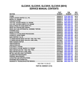
- 1. GLC20VX, GLC25VX, GLC30VX, GLC35VX (B910) SERVICE MANUAL CONTENTS SECTION PART NUMBER YRM NUMBER REV DATE FRAME............................................................................................................................ 550096314 0100 YRM 1672 04/14 KUBOTA SPARK IGNITED 2.5L LPG............................................................................ 550096316 0600 YRM 1670 12/14 MAZDA 2.2L ENGINE..................................................................................................... 550096315 0600 YRM 1673 04/14 COOLING SYSTEM........................................................................................................ 550096317 0700 YRM 1674 03/14 LPG FUEL SYSTEM, MAZDA 2.2L ENGINE................................................................. 550096318 0900 YRM 1675 03/14 LPG FUEL SYSTEM, KUBOTA 2.5L ENGINE............................................................... 550096320 0900 YRM 1677 12/14 SINGLE SPEED PS CHAIN DRIVE PTO........................................................................ 550096321 1300 YRM 1678 04/14 DRIVE AXLE REPAIR (WET BRAKE)........................................................................... 550096322 1400 YRM 1679 12/14 DRIVE AXLE AND DIFFERENTIAL ASSEMBLY REPAIR............................................ 550096323 1400 YRM 1680 04/14 STEERING AXLE............................................................................................................ 550096324 1600 YRM 1681 04/14 BRAKE SYSTEM............................................................................................................ 550096325 1800 YRM 1682 04/14 HYDRAULIC CLEANLINESS PROCEDURES............................................................... 550073240 1900 YRM 1620 12/14 HYDRAULIC GEAR PUMPS.......................................................................................... 550096326 1900 YRM 1683 04/14 MAIN CONTROL VALVE................................................................................................ 550096327 2000 YRM 1684 04/14 CYLINDER REPAIR (MAST S/N F507, F508, F562, F563)........................................... 550093750 2100 YRM 1668 12/14 CYLINDER REPAIR (MAST S/N D515, E509, E564)..................................................... 550100651 2100 YRM 1692 12/14 WIRE HARNESS REPAIR.............................................................................................. 524223769 2200 YRM 1128 12/14 USER INTERFACE......................................................................................................... 524223770 2200 YRM 1130 12/14 USER INTERFACE......................................................................................................... 524223771 2200 YRM 1131 12/14 ELECTRICAL SYSTEM.................................................................................................. 550096328 2200 YRM 1685 04/14 ELECTRICAL SYSTEM, MAZDA 2.2L ENGINE............................................................ 550096329 2200 YRM 1686 04/14 MAST REPAIR (S/N F507, F508, F562, F563)............................................................... 550093755 4000 YRM 1669 12/14 MAST REPAIR (S/N D515, E509, E564)........................................................................ 550100656 4000 YRM 1693 12/14 METRIC AND INCH (SAE) FASTENERS....................................................................... 524150797 8000 YRM 0231 10/13 CALIBRATION PROCEDURES...................................................................................... 524223780 8000 YRM 1134 12/14 PERIODIC MAINTENANCE............................................................................................ 550096309 8000 YRM 1687 05/14 CAPACITIES AND SPECIFICATIONS........................................................................... 550096330 8000 YRM 1688 04/14 DIAGRAMS AND SCHEMATICS.................................................................................... 550096331 8000 YRM 1689 04/14 DIAGNOSTIC TROUBLESHOOTING MANUAL............................................................ 524221866 9000 YRM 1112 12/14 9000 YRM 1112 ON CD PART NO. 550096301 (12/14)
- 2. General WARNING The lift truck must be put on blocks for some types of maintenance and repairs. The removal of the following assemblies will cause large changes in the center of gravity: mast, drive axle, engine and transmission, and counterweight. When the lift truck is put on blocks, put additional blocks in the following positions to maintain stability: • Before removing the mast and drive axle, put blocks under the counterweight so the lift truck cannot fall backward. • Before removing the counterweight, put blocks under the mast assembly so the lift truck cannot fall forward. The surface must be solid, even, and level when the lift truck is put on blocks. Make sure that any blocks used to support the lift truck are solid, one-piece units. See the Operating Manual or Periodic Maintenance 8000YRM1687. NOTE: For exhaust system procedures on lift trucks equipped with a Mazda engine go to LPG Fuel System, Mazda 2.2L Engine 0900YRM1675 or Gasoline Fuel System, Mazda 2.2L Engine 0900YRM1676 . NOTE: For exhaust system procedures on lift trucks equipped with Kubota engine go to LPG Fuel System, Kubota 2.5L Engine 0900YRM1677. NOTE: For exhaust system procedures on lift trucks equipped with Yanmar engine go to Exhaust System Repair in this manual. This section contains the description of the frame and connected parts; procedures for removing and installing counterweight, hood, overhead guard, engine, transmission, cooling system, and exhaust system (see above NOTES). Checks for the operator restraint system and procedures for the repair of tanks and installation of safety labels are also included. Description The frame is one weldment and includes the hydraulic tank and fuel tank for gasoline or diesel fuel. See Fig- ure 1. See Table 3 for lift truck models: • GLC20-35VX (GC/GLC40-70VX, GC/ GLC055SVX) (B910) See Table 4 for lift truck models: • GLP/GDP20-35VX (GP/GLP/GDP040-070VX) (C875) The muffler is fastened to the frame inside the coun- terweight. The overhead guard, cowl, and hood are installed on the frame. The hood is connected to the frame with hinges. Two gas-controlled springs provide assis- tance when raising the hood and hold the hood in the open position. The floor plate and side covers can be removed for access to the engine, transmission, and other components. 0100 YRM 1672 General 1
- 3. 1. COWL PLATE 2. FENDERS 3. FRAME 4. HOOD MOUNTS 5. COUNTERWEIGHT MOUNTS 6. FUEL TANK (GAS OR DIESEL) 7. HYDRAULIC TANK Figure 1. Frame Hood, Seat, and Side Covers Replacement REMOVE 1. Slide seat to the closest position to steering col- umn. 2. Fully tilt steering column forward. 3. If your truck is equipped with an LPG tank, swing tank off to the side. 4. Raise latch on the left, front corner of the hood to unlatch and lift up hood. See Figure 2. 5. Remove floor mat and floor plate. Hood, Seat, and Side Covers Replacement 0100 YRM 1672 2
- 4. NOTE: SWIVEL SEAT AND VENTED HOOD ARE OPTIONAL FEATURES. A. SIDE VIEW OF HOOD AND SEAT B. SIDE VIEW OF HOOD C. BOTTOM VIEW OF HOOD D. SIDE VIEW OF VENTED HOOD WITH SWIVEL SEAT 1. SEAT 2. HOOD 3. FRAME 4. SEAT WIRE HARNESS 5. SEAT WIRE HARNESS CONNECTOR (WITH- OUT ELECTRONIC CONTROL) 6. SEAT WIRE HARNESS CONNECTOR (WITH ELECTRONIC CONTROL) 7. CABLE CLIPS 8. HINGE SCREWS 9. GAS SPRING 10. ATTACHMENT HOLES ATTACHING HOOD TO SEAT (SEMI-SUSPENSION) 11. SEAT WIRE HARNESS BRACKETS 12. SEAT LINER 13. HOOD LATCH 14. ATTACHMENT HOLES ATTACHING HOOD TO SEAT (NON-SUSPENSION) 15. ATTACHMENT HOLES ATTACHING HOOD TO SEAT (FULL SUSPENSION) 16. SPACER Figure 2. Hood and Seat Arrangement 0100 YRM 1672 Hood, Seat, and Side Covers Replacement 3
- 5. Figure 3. Side Cover, Floor Plate, and Cowl Components GLC20-35VX (GC/GLC40-70VX, GC/ GLC055SVX) (B910) Hood, Seat, and Side Covers Replacement 0100 YRM 1672 4
- 6. Legend for Figure 3 1. LOWER STEERING COLUMN COVER 2. UPPER STEERING COLUMN COVER 3. INSERT 4. CLIP 5. DASHBOARD 6. CAPSCREW 7. SEAL 8. GROMMET 9. LEFT HAND REAR PANEL 10. FLOOR PLATE 11. LEFT HAND FENDER COVER 12. SCREW 13. NUT 14. LEFT HAND FRONT PANEL 15. LEFT HAND STEP PANEL 16. LEFT HAND TREAD PLATE 17. PLATE ASSEMBLY SEAL 18. RIGHT HAND FENDER COVER 19. FLOOR MAT 20. RIGHT HAND TREAD PLATE 21. RIGHT HAND FRONT PANEL 22. RIGHT HAND STEP PANEL 23. RIGHT HAND REAR PANEL 24. RADIATOR COVER 25. KICK PANEL 26. PLATE ASSEMBLY 0100 YRM 1672 Hood, Seat, and Side Covers Replacement 5
- 7. Figure 4. Side Covers, Floor Plate, and Cowl Components GLP/GDP20-35VX (GP/GLP/GDP040-070VX) (C875) Hood, Seat, and Side Covers Replacement 0100 YRM 1672 6
- 8. Legend for Figure 4 1. DASH ASSEMBLY 2. UPPER STEERING COLUMN COVER 3. LOWER STEERING COLUMN COVER 4. KICK PANEL 5. MUD GUARD (LH) 6. MUD GUARD (RH) 7. LOCK NUT 8. NUT 9. COVER 10. BRACKET 11. PLATE ASSEMBLY 12. GROMMET 13. LEFT FRONT PANEL 14. RIGHT FRONT PANEL 15. LEFT STEP PANEL 16. RIGHT STEP PANEL 17. LEFT STEP PLATE 18. RIGHT STEP PLATE 19. LEFT REAR PANEL 20. RIGHT REAR PANEL 21. FLOOR MAT 22. FLOOR PLATE 23. RADIATOR COVER 24. SEALS 25. CAPSCREW 26. CLIP NUT 27. INSERT 28. PLATE ASSEMBLY SEAL 6. Remove two capscrews holding left and right rear side covers to the frame. Remove rear side cov- ers from frame. 7. Remove two capscrews holding left and right fender covers to front overhead guard leg. Re- move covers. 8. Remove four capscrews holding left and right front side covers to frame. Remove covers. 9. Fully lower steering column. 10. Remove upper steering column cover by pulling up on upper steering column cover to release latches (one on either side), and pulling cover away from steering column. See Figure 5. 11. Remove five Allen screws (see Figure 5) from dash and cowl. Remove four clips, located under- neath dash, that attach dash to the kick panel. Lift to remove dash. 12. Lift the kick panel to remove from truck. 13. Remove three capscrews holding the seal plate. Remove seal plate. See Figure 6. 0100 YRM 1672 Hood, Seat, and Side Covers Replacement 7
- 9. Thank you very much for your reading. Please Click Here. Then Get COMPLETE MANUAL. NO WAITING NOTE: If there is no response to click on the link above, please download the PDF document first and then click on it.
- 10. NOTE: TOP VIEW OF DASH SHOWN. A. INDICATES TO PULL UP TO UNLATCH 1. ALLEN SCREWS 2. COWL 3. UPPER STEERING COLUMN COVER 4. LOWER STEERING COLUMN COVER Figure 5. Remove Dash From Cowl Hood, Seat, and Side Covers Replacement 0100 YRM 1672 8
- 11. 1. CAPSCREWS 2. SEAL PLATE Figure 6. Remove Seal Plate From Dash 0100 YRM 1672 Hood, Seat, and Side Covers Replacement 9
- 12. 14. Disconnect seat wire harness connector. See Fig- ure 2. CAUTION When removing the seat from the hood, DO NOT use an impact wrench to remove the capscrews. Damage can be caused to the threads on the screws and in the holes. 15. If seat is to be removed, and truck is equipped with a non-swivel seat, remove seat wire harness from seat wire harness brackets that are attached to the underside of hood. Remove the cable clips from the seat wire harness. If truck is equipped with a swivel seat, remove seat wire harness from seat wire harness bracket attached to underside of the hood and behind the seat (see Figure 2). 16. Remove four capscrews and washers holding the seat to hood. Lift seat off the hood. Pull seat wire harness through hood. See Figure 2. 17. Remove capscrews and washers at the top of gas springs. Remove gas springs from hood. 18. Remove hinge screws, located in the rear of the hood. 19. Lift hood from the truck. See Figure 2. INSTALL 1. Place hood onto the lift truck frame. 2. Install hinge screws, located in the rear of the hood, and tighten to 38 N•m (28 lbf ft). See Fig- ure 2. 3. Align top holes in the gas springs with holes in hood. Install capscrews and washers to attach gas springs to hood. Tighten capscrews to 19.2 N•m (170 lbf in). See Figure 7 and Table 1 for lift truck models: • GLC20-35VX (GC/GLC40-70VX, GC/ GLC055SVX) (B910) See Figure 8 and Table 2 for lift truck models • GLP/GDP20-35VX (GP/GLP/ GDP040-070VX) (C875) NOTE: LEFT SIDE SHOWN A. MOUNTING LOCATION FOR CYLINDER END OF GAS SPRING FOR NON-SUSPENSION SEAT B. MOUNTING LOCATION FOR CYLINDER END OF GAS SPRING FOR SEMI OR FULL SUS- PENSION SEAT C. MOUNTING LOCATION FOR CYLINDER END OF GAS SPRING FOR SEMI OR FULL SUS- PENSION SEAT WITH CAB 1. MOUNTING POINTS FOR GAS SPRING ON HOOD Figure 7. Gas Spring Installation, Lift Truck Models GLC20-35VX (GC/GLC40-70VX, GC/ GLC055SVX) (B910) Hood, Seat, and Side Covers Replacement 0100 YRM 1672 10
- 13. Table 1. Gas Spring Installation, Lift Truck Models GLC20-35VX (GC/GLC40-70VX, GC/ GLC055SVX) (B910) Full or Semi Suspension Seat Non-Suspension Seat Frame Hood Frame Hood Left Side Right Side Left Side Right Side Left Side Right Side Left Side Right Side Seat With- out E-Con- trol B B 3 3 A A 1 1 Seat With E-Control B B 2 2 N/A N/A N/A N/A Cab C C 2 2 N/A N/A N/A N/A A. LEFT SIDE B. RIGHT SIDE C. MOUNTING LOCATION FOR CYLINDER END OF GAS SPRING FOR NON-SUSPENSION SEAT D. MOUNTING LOCATION FOR CYLINDER END OF GAS SPRING FOR SEMI OR FULL SUS- PENSION SEAT, LIFT TRUCKS WITH CAB OR (GP/GLP/GDP040-070VX) (C875) LIFT TRUCKS WITHOUT CAB E. MOUNTING LOCATION FOR CYLINDER END OF GAS SPRING FOR SEMI OR FULL SUS- PENSION SEAT, LIFT TRUCKS GLP/ GDP20-35VX (C875) WITHOUT CAB 1. MOUNTING POINTS FOR GAS SPRING ON HOOD Figure 8. Gas Spring Installation, Lift Truck Models GLP/GDP20-35VX (GP/GLP/GDP040-070VX) (C875) 0100 YRM 1672 Hood, Seat, and Side Covers Replacement 11
- 14. Table 2. Gas Spring Installation, Lift Truck Models GLP/GDP20-35VX (GP/GLP/GDP040-070VX) (C875) Full or Semi Suspension Seat Non-Suspension Seat Frame Hood Frame Hood Left Side Right Side Left Side Right Side Left Side Right Side Left Side Right Side Non-Cab D D 3 3 C C 1 1 Non-Cab E E 2 2 C C 1 1 Cab D D 1 1 N/A N/A N/A N/A 4. Install latch striker in highest slot position. Check that latch striker is in center of jaws of hood latch when hood closes. Open and close hood to en- sure that center pin strikes hood latch properly and that the stop screw contacts frame. A prop- erly closed hood MUST click twice on the hood latch. If the hood latch does not close properly, loosen capscrews on the back of center pin and adjust center pin up or down as required for cor- rect alignment. See Figure 9. 1. HOOD 2. HOOD LATCH 3. CENTER PIN 4. CAPSCREW Figure 9. Hood Latch Adjustment Hood, Seat, and Side Covers Replacement 0100 YRM 1672 12