YALE (A974) GLP050LX LIFT TRUCK Service Repair Manualfjksemmmem
This is the Highly Detailed factory service repair manual for theYALE (A974) GLP050LX LIFT TRUCK, this Service Manual has detailed illustrations as well as step by step instructions,It is 100 percents complete and intact. they are specifically written for the do-it-yourself-er as well as the experienced mechanic.YALE (A974) GLP050LX LIFT TRUCK Service Repair Workshop Manual provides step-by-step instructions based on the complete dis-assembly of the machine. It is this level of detail, along with hundreds of photos and illustrations, that guide the reader through each service and repair procedure. Complete download comes in pdf format which can work under all PC based windows operating system and Mac also, All pages are printable. Using this repair manual is an inexpensive way to keep your vehicle working properly.
Service Repair Manual Covers:
Frame
Mazda fe and f2 engines
Y anmar diesel engines
Cooling system
Lpg fuel system mazda 2.0l and 2.2l 2007 emission compliant engines
Single speed powershift aluminum transmission repair
Single speed powershift aluminum chain drive transmission
Drive axle
Steering axle
Brake system
Hydraulic gear pump
Hydraulic cleanliness procedures
Main control valve
Cylinder repair (mast s/n a551, a555, a559, a661, a662, a663, a66, b507,
B508, b509, b551, b555, b559, b562, b563, b564, b661, b662, b663, c515,
C551, c555, c559, d507, d508, d509, d515, d562, d563, d564, e509, and e564)
Wire harness repair
Electrical system
Electrical system mazda 2.0l and 2.2l 2007 emission compliant engines
Mast repair (s/n a698, a699, b551)
Metric and inch (sae) fasteners
Periodic maintenance
Capacities and specifications
Schematics / diagrams
Diagnostic troubleshooting manual
File Format: PDF
Compatible: All Versions of Windows & Mac
Language: English
Requirements: Adobe PDF Reader
NO waiting, Buy from responsible seller and get INSTANT DOWNLOAD, Without wasting your hard-owned money on uncertainty or surprise! All pages are is great to haveYALE (A974) GLP050LX LIFT TRUCK Service Repair Workshop Manual.
Looking for some other Service Repair Manual,please check:
https://www.aservicemanualpdf.com/
Thanks for visiting!
YALE F818 GLC40VX LIFT TRUCK (EUROPE) Service Repair Manualjkseodlpled
This is the Highly Detailed factory service repair manual for theYALE F818 GLC40VX LIFT TRUCK, this Service Manual has detailed illustrations as well as step by step instructions,It is 100 percents complete and intact. they are specifically written for the do-it-yourself-er as well as the experienced mechanic.YALE F818 GLC40VX LIFT TRUCK Service Repair Workshop Manual provides step-by-step instructions based on the complete dis-assembly of the machine. It is this level of detail, along with hundreds of photos and illustrations, that guide the reader through each service and repair procedure. Complete download comes in pdf format which can work under all PC based windows operating system and Mac also, All pages are printable. Using this repair manual is an inexpensive way to keep your vehicle working properly.
Service Repair Manual Covers:
Frame
Gm 4.3l v-6 engines
Cooling system
Lpg fuel system gm 4.3l engine with psi
1 and 2 sp ps transmission repair
Drive axle and differential assembly repair
Steering axle
Wet brakes - nmhg
Hydraulic gear pump
Hydraulic cleanliness procedures
Main control valve
Cylinder repair (mast s/n a551, a555, a559, a661, a662, a663, a66, b507,
B508, b509, b551, b555, b559, b562, b563, b564, b661, b662, b663, c515,
C551, c555, c559, d507, d508, d509, d515, d562, d563, d564, e509, and e564)
High voltage switch (hvs) ignition
Wire harness repair
User interface
Electrical system
Mast repairs (s/n a513, a514, a613, a614, a702, a703, a704, a705, a706,
A707, a751, a752, b513, b514, b586, b587, b588, b589, b590, b591, b749, b750, b751, b752, b753, b754)
Metric and inch (sae) fasteners
Calibration procedures
Diagrams and schematics
Periodic maintenance
Capacities and specifications
Diagrams and schematics
Diagnostic troubleshooting manual
File Format: PDF
Compatible: All Versions of Windows & Mac
Language: English
Requirements: Adobe PDF Reader
NO waiting, Buy from responsible seller and get INSTANT DOWNLOAD, Without wasting your hard-owned money on uncertainty or surprise! All pages are is great to haveYALE F818 GLC40VX LIFT TRUCK Service Repair Workshop Manual.
Looking for some other Service Repair Manual,please check:
https://www.aservicemanualpdf.com/
Thanks for visiting!
8
YALE F818 GLC55SVX LIFT TRUCK (EUROPE) Service Repair Manualyehnmdm jnkmem
This is the Highly Detailed factory service repair manual for theYALE F818 GLC55SVX LIFT TRUCK, this Service Manual has detailed illustrations as well as step by step instructions,It is 100 percents complete and intact. they are specifically written for the do-it-yourself-er as well as the experienced mechanic.YALE F818 GLC55SVX LIFT TRUCK Service Repair Workshop Manual provides step-by-step instructions based on the complete dis-assembly of the machine. It is this level of detail, along with hundreds of photos and illustrations, that guide the reader through each service and repair procedure. Complete download comes in pdf format which can work under all PC based windows operating system and Mac also, All pages are printable. Using this repair manual is an inexpensive way to keep your vehicle working properly.
Service Repair Manual Covers:
Frame
Gm 4.3l v-6 engines
Cooling system
Lpg fuel system gm 4.3l engine with psi
1 and 2 sp ps transmission repair
Drive axle and differential assembly repair
Steering axle
Wet brakes - nmhg
Hydraulic gear pump
Hydraulic cleanliness procedures
Main control valve
Cylinder repair (mast s/n a551, a555, a559, a661, a662, a663, a66, b507,
B508, b509, b551, b555, b559, b562, b563, b564, b661, b662, b663, c515,
C551, c555, c559, d507, d508, d509, d515, d562, d563, d564, e509, and e564)
High voltage switch (hvs) ignition
Wire harness repair
User interface
Electrical system
Mast repairs (s/n a513, a514, a613, a614, a702, a703, a704, a705, a706,
A707, a751, a752, b513, b514, b586, b587, b588, b589, b590, b591, b749, b750, b751, b752, b753, b754)
Metric and inch (sae) fasteners
Calibration procedures
Diagrams and schematics
Periodic maintenance
Capacities and specifications
Diagrams and schematics
Diagnostic troubleshooting manual
File Format: PDF
Compatible: All Versions of Windows & Mac
Language: English
Requirements: Adobe PDF Reader
NO waiting, Buy from responsible seller and get INSTANT DOWNLOAD, Without wasting your hard-owned money on uncertainty or surprise! All pages are is great to haveYALE F818 GLC55SVX LIFT TRUCK Service Repair Workshop Manual.
Looking for some other Service Repair Manual,please check:
https://www.aservicemanualpdf.com/
Thanks for visiting!
8
YALE F818 GLC45VX LIFT TRUCK (EUROPE) Service Repair Manualjkskmdkemde
This is the Highly Detailed factory service repair manual for theYALE F818 GLC45VX LIFT TRUCK, this Service Manual has detailed illustrations as well as step by step instructions,It is 100 percents complete and intact. they are specifically written for the do-it-yourself-er as well as the experienced mechanic.YALE F818 GLC45VX LIFT TRUCK Service Repair Workshop Manual provides step-by-step instructions based on the complete dis-assembly of the machine. It is this level of detail, along with hundreds of photos and illustrations, that guide the reader through each service and repair procedure. Complete download comes in pdf format which can work under all PC based windows operating system and Mac also, All pages are printable. Using this repair manual is an inexpensive way to keep your vehicle working properly.
Service Repair Manual Covers:
Frame
Gm 4.3l v-6 engines
Cooling system
Lpg fuel system gm 4.3l engine with psi
1 and 2 sp ps transmission repair
Drive axle and differential assembly repair
Steering axle
Wet brakes - nmhg
Hydraulic gear pump
Hydraulic cleanliness procedures
Main control valve
Cylinder repair (mast s/n a551, a555, a559, a661, a662, a663, a66, b507,
B508, b509, b551, b555, b559, b562, b563, b564, b661, b662, b663, c515,
C551, c555, c559, d507, d508, d509, d515, d562, d563, d564, e509, and e564)
High voltage switch (hvs) ignition
Wire harness repair
User interface
Electrical system
Mast repairs (s/n a513, a514, a613, a614, a702, a703, a704, a705, a706,
A707, a751, a752, b513, b514, b586, b587, b588, b589, b590, b591, b749, b750, b751, b752, b753, b754)
Metric and inch (sae) fasteners
Calibration procedures
Diagrams and schematics
Periodic maintenance
Capacities and specifications
Diagrams and schematics
Diagnostic troubleshooting manual
File Format: PDF
Compatible: All Versions of Windows & Mac
Language: English
Requirements: Adobe PDF Reader
NO waiting, Buy from responsible seller and get INSTANT DOWNLOAD, Without wasting your hard-owned money on uncertainty or surprise! All pages are is great to haveYALE F818 GLC45VX LIFT TRUCK Service Repair Workshop Manual.
Looking for some other Service Repair Manual,please check:
https://www.aservicemanualpdf.com/
Thanks for visiting!
8
YALE F818 GLC55VX LIFT TRUCK (EUROPE) Service Repair Manualjkskemeedmm
This is the Highly Detailed factory service repair manual for theYALE F818 GLC55VX LIFT TRUCK, this Service Manual has detailed illustrations as well as step by step instructions,It is 100 percents complete and intact. they are specifically written for the do-it-yourself-er as well as the experienced mechanic.YALE F818 GLC55VX LIFT TRUCK Service Repair Workshop Manual provides step-by-step instructions based on the complete dis-assembly of the machine. It is this level of detail, along with hundreds of photos and illustrations, that guide the reader through each service and repair procedure. Complete download comes in pdf format which can work under all PC based windows operating system and Mac also, All pages are printable. Using this repair manual is an inexpensive way to keep your vehicle working properly.
Service Repair Manual Covers:
Frame
Gm 4.3l v-6 engines
Cooling system
Lpg fuel system gm 4.3l engine with psi
1 and 2 sp ps transmission repair
Drive axle and differential assembly repair
Steering axle
Wet brakes - nmhg
Hydraulic gear pump
Hydraulic cleanliness procedures
Main control valve
Cylinder repair (mast s/n a551, a555, a559, a661, a662, a663, a66, b507,
B508, b509, b551, b555, b559, b562, b563, b564, b661, b662, b663, c515,
C551, c555, c559, d507, d508, d509, d515, d562, d563, d564, e509, and e564)
High voltage switch (hvs) ignition
Wire harness repair
User interface
Electrical system
Mast repairs (s/n a513, a514, a613, a614, a702, a703, a704, a705, a706,
A707, a751, a752, b513, b514, b586, b587, b588, b589, b590, b591, b749, b750, b751, b752, b753, b754)
Metric and inch (sae) fasteners
Calibration procedures
Diagrams and schematics
Periodic maintenance
Capacities and specifications
Diagrams and schematics
Diagnostic troubleshooting manual
File Format: PDF
Compatible: All Versions of Windows & Mac
Language: English
Requirements: Adobe PDF Reader
NO waiting, Buy from responsible seller and get INSTANT DOWNLOAD, Without wasting your hard-owned money on uncertainty or surprise! All pages are is great to haveYALE F818 GLC55VX LIFT TRUCK Service Repair Workshop Manual.
Looking for some other Service Repair Manual,please check:
https://www.aservicemanualpdf.com/
Thanks for visiting!
8
YALE B974 GDP20LX LIFT TRUCK Service Repair Manualeidkmm fksemm
This is the Highly Detailed factory service repair manual for theYALE B974 GDP20LX LIFT TRUCK, this Service Manual has detailed illustrations as well as step by step instructions,It is 100 percents complete and intact. they are specifically written for the do-it-yourself-er as well as the experienced mechanic.YALE B974 GDP20LX LIFT TRUCK Service Repair Workshop Manual provides step-by-step instructions based on the complete dis-assembly of the machine. It is this level of detail, along with hundreds of photos and illustrations, that guide the reader through each service and repair procedure. Complete download comes in pdf format which can work under all PC based windows operating system and Mac also, All pages are printable. Using this repair manual is an inexpensive way to keep your vehicle working properly.
Service Repair Manual Covers:
Frame
Y anmar diesel engines
Psi 2.4l engine
Cooling system
Fuel system psi 2.4l
Single speed ps chain drive pto
Drive axle and differential assembly repair
Steering axle repair
Brake system
Hydraulic cleanliness procedures
Hydraulic gear pumps
Main control valve
Cylinder repair (mast s/n a698 and a699)
Wire harness repair
Electrical system
Engine electrical system, psi 2.4l engine
Mast repair (s/n a698 and a699)
Metric and inch (sae) fasteners
Periodic maintenance
Capacities and specifications
Diagrams and schematics
Diagnostic troubleshooting manual
File Format: PDF
Compatible: All Versions of Windows & Mac
Language: English
Requirements: Adobe PDF Reader
NO waiting, Buy from responsible seller and get INSTANT DOWNLOAD, Without wasting your hard-owned money on uncertainty or surprise! All pages are is great to haveYALE B974 GDP20LX LIFT TRUCK Service Repair Workshop Manual.
Looking for some other Service Repair Manual,please check:
https://www.aservicemanualpdf.com/
Thanks for visiting!
8
YALE B974 GDP25LX LIFT TRUCK Service Repair Manualqwuikm
This is the Highly Detailed factory service repair manual for theYALE B974 GDP25LX LIFT TRUCK, this Service Manual has detailed illustrations as well as step by step instructions,It is 100 percents complete and intact. they are specifically written for the do-it-yourself-er as well as the experienced mechanic.YALE B974 GDP25LX LIFT TRUCK Service Repair Workshop Manual provides step-by-step instructions based on the complete dis-assembly of the machine. It is this level of detail, along with hundreds of photos and illustrations, that guide the reader through each service and repair procedure. Complete download comes in pdf format which can work under all PC based windows operating system and Mac also, All pages are printable. Using this repair manual is an inexpensive way to keep your vehicle working properly.
Service Repair Manual Covers:
Frame
Y anmar diesel engines
Psi 2.4l engine
Cooling system
Fuel system psi 2.4l
Single speed ps chain drive pto
Drive axle and differential assembly repair
Steering axle repair
Brake system
Hydraulic cleanliness procedures
Hydraulic gear pumps
Main control valve
Cylinder repair (mast s/n a698 and a699)
Wire harness repair
Electrical system
Engine electrical system, psi 2.4l engine
Mast repair (s/n a698 and a699)
Metric and inch (sae) fasteners
Periodic maintenance
Capacities and specifications
Diagrams and schematics
Diagnostic troubleshooting manual
File Format: PDF
Compatible: All Versions of Windows & Mac
Language: English
Requirements: Adobe PDF Reader
NO waiting, Buy from responsible seller and get INSTANT DOWNLOAD, Without wasting your hard-owned money on uncertainty or surprise! All pages are is great to haveYALE B974 GDP25LX LIFT TRUCK Service Repair Workshop Manual.
Looking for some other Service Repair Manual,please check:
https://www.aservicemanualpdf.com/
Thanks for visiting!
8
YALE B974 GDP25LX LIFT TRUCK Service Repair Manualjksnemmd
This is the Highly Detailed factory service repair manual for theYALE B974 GDP25LX LIFT TRUCK, this Service Manual has detailed illustrations as well as step by step instructions,It is 100 percents complete and intact. they are specifically written for the do-it-yourself-er as well as the experienced mechanic.YALE B974 GDP25LX LIFT TRUCK Service Repair Workshop Manual provides step-by-step instructions based on the complete dis-assembly of the machine. It is this level of detail, along with hundreds of photos and illustrations, that guide the reader through each service and repair procedure. Complete download comes in pdf format which can work under all PC based windows operating system and Mac also, All pages are printable. Using this repair manual is an inexpensive way to keep your vehicle working properly.
Service Repair Manual Covers:
Frame
Y anmar diesel engines
Psi 2.4l engine
Cooling system
Fuel system psi 2.4l
Single speed ps chain drive pto
Drive axle and differential assembly repair
Steering axle repair
Brake system
Hydraulic cleanliness procedures
Hydraulic gear pumps
Main control valve
Cylinder repair (mast s/n a698 and a699)
Wire harness repair
Electrical system
Engine electrical system, psi 2.4l engine
Mast repair (s/n a698 and a699)
Metric and inch (sae) fasteners
Periodic maintenance
Capacities and specifications
Diagrams and schematics
Diagnostic troubleshooting manual
File Format: PDF
Compatible: All Versions of Windows & Mac
Language: English
Requirements: Adobe PDF Reader
NO waiting, Buy from responsible seller and get INSTANT DOWNLOAD, Without wasting your hard-owned money on uncertainty or surprise! All pages are is great to haveYALE B974 GDP25LX LIFT TRUCK Service Repair Workshop Manual.
Looking for some other Service Repair Manual,please check:
https://www.aservicemanualpdf.com/
Thanks for visiting!
8
YALE B974 GLP25LX LIFT TRUCK Service Repair Manualjkmsemmd
This is the Highly Detailed factory service repair manual for theYALE B974 GLP25LX LIFT TRUCK, this Service Manual has detailed illustrations as well as step by step instructions,It is 100 percents complete and intact. they are specifically written for the do-it-yourself-er as well as the experienced mechanic.YALE B974 GLP25LX LIFT TRUCK Service Repair Workshop Manual provides step-by-step instructions based on the complete dis-assembly of the machine. It is this level of detail, along with hundreds of photos and illustrations, that guide the reader through each service and repair procedure. Complete download comes in pdf format which can work under all PC based windows operating system and Mac also, All pages are printable. Using this repair manual is an inexpensive way to keep your vehicle working properly.
Service Repair Manual Covers:
Frame
Y anmar diesel engines
Psi 2.4l engine
Cooling system
Fuel system psi 2.4l
Single speed ps chain drive pto
Drive axle and differential assembly repair
Steering axle repair
Brake system
Hydraulic cleanliness procedures
Hydraulic gear pumps
Main control valve
Cylinder repair (mast s/n a698 and a699)
Wire harness repair
Electrical system
Engine electrical system, psi 2.4l engine
Mast repair (s/n a698 and a699)
Metric and inch (sae) fasteners
Periodic maintenance
Capacities and specifications
Diagrams and schematics
Diagnostic troubleshooting manual
File Format: PDF
Compatible: All Versions of Windows & Mac
Language: English
Requirements: Adobe PDF Reader
NO waiting, Buy from responsible seller and get INSTANT DOWNLOAD, Without wasting your hard-owned money on uncertainty or surprise! All pages are is great to haveYALE B974 GLP25LX LIFT TRUCK Service Repair Workshop Manual.
Looking for some other Service Repair Manual,please check:
https://www.aservicemanualpdf.com/
Thanks for visiting!
8
YALE B974 GLP25LX LIFT TRUCK Service Repair Manualkusekdmmytv
This is the Highly Detailed factory service repair manual for theYALE B974 GLP25LX LIFT TRUCK, this Service Manual has detailed illustrations as well as step by step instructions,It is 100 percents complete and intact. they are specifically written for the do-it-yourself-er as well as the experienced mechanic.YALE B974 GLP25LX LIFT TRUCK Service Repair Workshop Manual provides step-by-step instructions based on the complete dis-assembly of the machine. It is this level of detail, along with hundreds of photos and illustrations, that guide the reader through each service and repair procedure. Complete download comes in pdf format which can work under all PC based windows operating system and Mac also, All pages are printable. Using this repair manual is an inexpensive way to keep your vehicle working properly.
Service Repair Manual Covers:
Frame
Y anmar diesel engines
Psi 2.4l engine
Cooling system
Fuel system psi 2.4l
Single speed ps chain drive pto
Drive axle and differential assembly repair
Steering axle repair
Brake system
Hydraulic cleanliness procedures
Hydraulic gear pumps
Main control valve
Cylinder repair (mast s/n a698 and a699)
Wire harness repair
Electrical system
Engine electrical system, psi 2.4l engine
Mast repair (s/n a698 and a699)
Metric and inch (sae) fasteners
Periodic maintenance
Capacities and specifications
Diagrams and schematics
Diagnostic troubleshooting manual
File Format: PDF
Compatible: All Versions of Windows & Mac
Language: English
Requirements: Adobe PDF Reader
NO waiting, Buy from responsible seller and get INSTANT DOWNLOAD, Without wasting your hard-owned money on uncertainty or surprise! All pages are is great to haveYALE B974 GLP25LX LIFT TRUCK Service Repair Workshop Manual.
Looking for some other Service Repair Manual,please check:
https://www.aservicemanualpdf.com/
Thanks for visiting!
8
YALE B974 GLP20LX LIFT TRUCK Service Repair Manualjkmsedol
This is the Highly Detailed factory service repair manual for theYALE B974 GLP20LX LIFT TRUCK, this Service Manual has detailed illustrations as well as step by step instructions,It is 100 percents complete and intact. they are specifically written for the do-it-yourself-er as well as the experienced mechanic.YALE B974 GLP20LX LIFT TRUCK Service Repair Workshop Manual provides step-by-step instructions based on the complete dis-assembly of the machine. It is this level of detail, along with hundreds of photos and illustrations, that guide the reader through each service and repair procedure. Complete download comes in pdf format which can work under all PC based windows operating system and Mac also, All pages are printable. Using this repair manual is an inexpensive way to keep your vehicle working properly.
Service Repair Manual Covers:
Frame
Y anmar diesel engines
Psi 2.4l engine
Cooling system
Fuel system psi 2.4l
Single speed ps chain drive pto
Drive axle and differential assembly repair
Steering axle repair
Brake system
Hydraulic cleanliness procedures
Hydraulic gear pumps
Main control valve
Cylinder repair (mast s/n a698 and a699)
Wire harness repair
Electrical system
Engine electrical system, psi 2.4l engine
Mast repair (s/n a698 and a699)
Metric and inch (sae) fasteners
Periodic maintenance
Capacities and specifications
Diagrams and schematics
Diagnostic troubleshooting manual
File Format: PDF
Compatible: All Versions of Windows & Mac
Language: English
Requirements: Adobe PDF Reader
NO waiting, Buy from responsible seller and get INSTANT DOWNLOAD, Without wasting your hard-owned money on uncertainty or surprise! All pages are is great to haveYALE B974 GLP20LX LIFT TRUCK Service Repair Workshop Manual.
Looking for some other Service Repair Manual,please check:
https://www.aservicemanualpdf.com/
Thanks for visiting!
8
Similar to Yale a967 glc050 lx lift truck service repair manual (14)
5 Warning Signs Your BMW's Intelligent Battery Sensor Needs AttentionBertini's German Motors
IBS monitors and manages your BMW’s battery performance. If it malfunctions, you will have to deal with an array of electrical issues in your vehicle. Recognize warning signs like dimming headlights, frequent battery replacements, and electrical malfunctions to address potential IBS issues promptly.
Core technology of Hyundai Motor Group's EV platform 'E-GMP'Hyundai Motor Group
What’s the force behind Hyundai Motor Group's EV performance and quality?
Maximized driving performance and quick charging time through high-density battery pack and fast charging technology and applicable to various vehicle types!
Discover more about Hyundai Motor Group’s EV platform ‘E-GMP’!
What Does the PARKTRONIC Inoperative, See Owner's Manual Message Mean for You...Autohaus Service and Sales
Learn what "PARKTRONIC Inoperative, See Owner's Manual" means for your Mercedes-Benz. This message indicates a malfunction in the parking assistance system, potentially due to sensor issues or electrical faults. Prompt attention is crucial to ensure safety and functionality. Follow steps outlined for diagnosis and repair in the owner's manual.
Ever been troubled by the blinking sign and didn’t know what to do?
Here’s a handy guide to dashboard symbols so that you’ll never be confused again!
Save them for later and save the trouble!
Things to remember while upgrading the brakes of your carjennifermiller8137
Upgrading the brakes of your car? Keep these things in mind before doing so. Additionally, start using an OBD 2 GPS tracker so that you never miss a vehicle maintenance appointment. On top of this, a car GPS tracker will also let you master good driving habits that will let you increase the operational life of your car’s brakes.
In this presentation, we have discussed a very important feature of BMW X5 cars… the Comfort Access. Things that can significantly limit its functionality. And things that you can try to restore the functionality of such a convenient feature of your vehicle.
What Exactly Is The Common Rail Direct Injection System & How Does It WorkMotor Cars International
Learn about Common Rail Direct Injection (CRDi) - the revolutionary technology that has made diesel engines more efficient. Explore its workings, advantages like enhanced fuel efficiency and increased power output, along with drawbacks such as complexity and higher initial cost. Compare CRDi with traditional diesel engines and discover why it's the preferred choice for modern engines.
Fleet management these days is next to impossible without connected vehicle solutions. Why? Well, fleet trackers and accompanying connected vehicle management solutions tend to offer quite a few hard-to-ignore benefits to fleet managers and businesses alike. Let’s check them out!
Comprehensive program for Agricultural Finance, the Automotive Sector, and Empowerment . We will define the full scope and provide a detailed two-week plan for identifying strategic partners in each area within Limpopo, including target areas.:
1. Agricultural : Supporting Primary and Secondary Agriculture
• Scope: Provide support solutions to enhance agricultural productivity and sustainability.
• Target Areas: Polokwane, Tzaneen, Thohoyandou, Makhado, and Giyani.
2. Automotive Sector: Partnerships with Mechanics and Panel Beater Shops
• Scope: Develop collaborations with automotive service providers to improve service quality and business operations.
• Target Areas: Polokwane, Lephalale, Mokopane, Phalaborwa, and Bela-Bela.
3. Empowerment : Focusing on Women Empowerment
• Scope: Provide business support support and training to women-owned businesses, promoting economic inclusion.
• Target Areas: Polokwane, Thohoyandou, Musina, Burgersfort, and Louis Trichardt.
We will also prioritize Industrial Economic Zone areas and their priorities.
Sign up on https://profilesmes.online/welcome/
To be eligible:
1. You must have a registered business and operate in Limpopo
2. Generate revenue
3. Sectors : Agriculture ( primary and secondary) and Automative
Women and Youth are encouraged to apply even if you don't fall in those sectors.
"Trans Failsafe Prog" on your BMW X5 indicates potential transmission issues requiring immediate action. This safety feature activates in response to abnormalities like low fluid levels, leaks, faulty sensors, electrical or mechanical failures, and overheating.
𝘼𝙣𝙩𝙞𝙦𝙪𝙚 𝙋𝙡𝙖𝙨𝙩𝙞𝙘 𝙏𝙧𝙖𝙙𝙚𝙧𝙨 𝙞𝙨 𝙫𝙚𝙧𝙮 𝙛𝙖𝙢𝙤𝙪𝙨 𝙛𝙤𝙧 𝙢𝙖𝙣𝙪𝙛𝙖𝙘𝙩𝙪𝙧𝙞𝙣𝙜 𝙩𝙝𝙚𝙞𝙧 𝙥𝙧𝙤𝙙𝙪𝙘𝙩𝙨. 𝙒𝙚 𝙝𝙖𝙫𝙚 𝙖𝙡𝙡 𝙩𝙝𝙚 𝙥𝙡𝙖𝙨𝙩𝙞𝙘 𝙜𝙧𝙖𝙣𝙪𝙡𝙚𝙨 𝙪𝙨𝙚𝙙 𝙞𝙣 𝙖𝙪𝙩𝙤𝙢𝙤𝙩𝙞𝙫𝙚 𝙖𝙣𝙙 𝙖𝙪𝙩𝙤 𝙥𝙖𝙧𝙩𝙨 𝙖𝙣𝙙 𝙖𝙡𝙡 𝙩𝙝𝙚 𝙛𝙖𝙢𝙤𝙪𝙨 𝙘𝙤𝙢𝙥𝙖𝙣𝙞𝙚𝙨 𝙗𝙪𝙮 𝙩𝙝𝙚 𝙜𝙧𝙖𝙣𝙪𝙡𝙚𝙨 𝙛𝙧𝙤𝙢 𝙪𝙨.
Over the 10 years, we have gained a strong foothold in the market due to our range's high quality, competitive prices, and time-lined delivery schedules.
Bài tập - Tiếng anh 11 Global Success UNIT 1 - Bản HS.doc
Yale a967 glc050 lx lift truck service repair manual
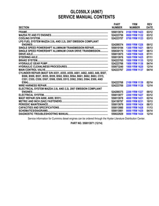
1. GLC050LX (A967)
SERVICE MANUAL CONTENTS
SECTION
PART
NUMBER
YRM
NUMBER
REV
DATE
FRAME............................................................................................................................ 550013974 0100 YRM 1423 03/12
MAZDA FE AND F2 ENGINES....................................................................................... 524223756 0600 YRM 1122 03/12
COOLING SYSTEM........................................................................................................ 524223757 0700 YRM 1123 03/13
LPG FUEL SYSTEM MAZDA 2.0L AND 2.2L 2007 EMISSION COMPLIANT
ENGINES.................................................................................................................... 524289374 0900 YRM 1326 09/12
SINGLE SPEED POWERSHIFT ALUMINUM TRANSMISSION REPAIR..................... 550010194 1300 YRM 1421 08/13
SINGLE SPEED POWERSHIFT ALUMINUM CHAIN DRIVE TRANSMISSION............ 550030170 1300 YRM 1447 08/13
DRIVE AXLE................................................................................................................... 550013975 1400 YRM 1426 07/11
STEERING AXLE............................................................................................................ 550013976 1600 YRM 1425 07/11
BRAKE SYSTEM............................................................................................................ 524223765 1800 YRM 1135 12/12
HYDRAULIC GEAR PUMP............................................................................................. 524223766 1900 YRM 1136 04/14
HYDRAULIC CLEANLINESS PROCEDURES............................................................... 550073240 1900 YRM 1620 12/14
MAIN CONTROL VALVE................................................................................................ 524223767 2000 YRM 1137 04/14
CYLINDER REPAIR (MAST S/N A551, A555, A559, A661, A662, A663, A66, B507,
B508, B509, B551, B555, B559, B562, B563, B564, B661, B662, B663, C515,
C551, C555, C559, D507, D508, D509, D515, D562, D563, D564, E509, AND
E564).......................................................................................................................... 524223768 2100 YRM 1139 02/14
WIRE HARNESS REPAIR.............................................................................................. 524223769 2200 YRM 1128 12/14
ELECTRICAL SYSTEM MAZDA 2.0L AND 2.2L 2007 EMISSION COMPLIANT
ENGINES.................................................................................................................... 524289375 2200 YRM 1327 09/12
ELECTRICAL SYSTEM.................................................................................................. 550013977 2200 YRM 1427 03/12
MAST REPAIR (S/N A698, A699, B551)........................................................................ 550013978 4000 YRM 1431 02/14
METRIC AND INCH (SAE) FASTENERS....................................................................... 524150797 8000 YRM 0231 10/13
PERIODIC MAINTENANCE............................................................................................ 550013979 8000 YRM 1424 08/13
CAPACITIES AND SPECIFICATIONS........................................................................... 550013980 8000 YRM 1428 11/13
SCHEMATICS/DIAGRAMS............................................................................................ 550013981 8000 YRM 1429 04/14
DIAGNOSTIC TROUBLESHOOTING MANUAL............................................................ 550022929 9000 YRM 1434 12/14
Service information for Cummins diesel engines can be ordered through the Hyster Literature Distribution Center.
PART NO. 550013971 (12/14)
2. 100 YRM 1423 General
General
WARNING
The lift truck must be put on blocks for some types
of maintenance and repairs. The removal of the
following assemblies will cause large changes in
the center of gravity: mast, drive axle, engine and
transmission, and counterweight. When the lift
truck is put on blocks, put additional blocks in the
following positions to maintain stability:
• Before removing the mast and drive axle, put
blocks under the counterweight so the lift truck
cannot fall backward.
• Before removing the counterweight, put blocks
under the mast assembly so the lift truck cannot
fall forward.
The surface must be solid, even, and level when the
lift truck is put on blocks. Make sure that any blocks
used to support the lift truck are solid, one-piece
units. See the Operating Manual or the section Pe-
riodic Maintenance 8000 YRM 1424.
This section contains the description of the frame (see
Figure 1) and connected parts. Procedures for remov-
ing and installing the counterweight, hood, overhead
guard, engine, and cooling system are found in this sec-
tion. Checks for the operator restraint system, adjust-
ments for the throttle pedal stop, and procedures for the
repair of tanks and installation of safety labels are also
included.
1. COWL PLATE
2. FENDER
3. FRAME
4. HOOD MOUNT
5. COUNTERWEIGHT SUPPORT
6. LEFT-HAND FRAME WELDMENT
7. HYDRAULIC TANK
Figure 1. Frame
1
3. Hood, Seat, and Side Covers Replacement 100 YRM 1423
Hood, Seat, and Side Covers Replacement
REMOVE
1. Slide the seat to the closest position to the steering
column.
2. Fully tilt the steering column forward.
NOTE: Perform Step 3 for lift trucks equipped with LPG.
3. Swing LPG tank off to side. See LPG Fuel System,
Mazda FE and F2 Emission Compliant Engines
900 YRM 1326 for procedures.
4. Raise the hood latch on the left, front corner of the
hood to unlatch and lift up the hood. See Figure 2.
5. Remove the floor mat and floor plate. See Figure 3.
6. Remove the two capscrews holding the left and
right rear side covers to the frame. Remove the rear
side covers from the frame. See Figure 3.
7. Remove the four capscrews and clip nuts holding
the left and right front side covers and left and right
cowl plates to the frame. Remove front side covers
and cowl plates.
8. Fully lower the steering column.
1. HOOD LATCH
2. SEAT
3. HOOD
Figure 2. Hood Latch
Legend for Figure 3
1. DASH ASSEMBLY
2. UPPER STEERING COLUMN COVER
3. LOWER STEERING COLUMN COVER
4. KICK PANEL
5. PLATE ASSEMBLY
6. GROMMET
7. LEFT FRONT SIDE COVER
8. RIGHT FRONT SIDE COVER
9. LEFT STEP PANEL
10. RIGHT STEP PANEL
11. LEFT STEP PLATE
12. RIGHT STEP PLATE
13. LEFT REAR SIDE COVER
14. RIGHT REAR SIDE COVER
15. FLOOR MAT
16. FLOOR PLATE
17. RADIATOR COVER
18. SEALS
19. CAPSCREW
20. CLIP NUT
21. INSERT
22. PLATE ASSEMBLY SEAL
23. LEFT COWL PLATE
24. RIGHT COWL PLATE
2
4. 100 YRM 1423 Hood, Seat, and Side Covers Replacement
Figure 3. Side Cover, Floor Plate, and Cowl Components
3
5. Hood, Seat, and Side Covers Replacement 100 YRM 1423
9. Remove upper steering column cover by pulling up
on the base of the upper steering column cover to
release the latches (one on either side), and pulling
cover away from steering column. See Figure 4.
10. Remove the five Allen Head screws (see Figure 4)
securing the dash to top of cowl.
11. Pull kick panel up from bottom and out to remove
kick panel from seal plate and clips on dash panel.
12. Remove dash panel from cowl. See Figure 5.
13. Remove three capscrews holding the seal plate.
Remove seal plate. See Figure 5.
NOTE: TOP VIEW OF DASH PANEL SHOWN
A. INDICATES TO PULL UP TO UNLATCH
1. ALLEN HEAD SCREWS
2. COWL
3. UPPER STEERING COLUMN COVER
4. LOWER STEERING COLUMN COVER
Figure 4. Dash Panel and Upper Steering Column Cover Removal
4
6. 100 YRM 1423 Hood, Seat, and Side Covers Replacement
1. ALLEN HEAD SCREWS
2. COWL
3. DASH PANEL
4. KICK PANEL
5. KICK PANEL NOTCHES
6. SEAL PLATE
7. CAPSCREWS
8. CLIPS
Figure 5. Dash Panel, Kick Panel, and Seal Plate Removal
5
7. Hood, Seat, and Side Covers Replacement 100 YRM 1423
14. Remove two capscrews and washers from cover
plate and remove electrical cover. Disconnect seat
harness from chassis harness. See Figure 6.
CAUTION
When removing the seat from the hood, do not use
an impact wrench to remove the capscrews. Dam-
age can be caused to the threads on the capscrews
and in the holes.
15. Open hood and pull chassis harness through hole
in hood. See Figure 7. Remove the four capscrews
and nuts holding the seat to the hood. Lift the seat
off the hood. See Figure 7. Close hood.
16. Remove the nuts from ball studs on gas springs.
Remove gas springs from the hood. See Figure 8.
17. Remove the hinge capscrews and nuts, located in
the rear of the hood. See Figure 8.
18. Lift the hood from the truck.
A. NON-SUSPENSION SEAT B. FULL SUSPENSION SEAT
1. CAPSCREWS
2. WASHER
3. COVER PLATE
4. ELECTRICAL CONNECTOR (SEAT HARNESS)
5. ELECTRICAL COVER
Figure 6. Disconnect Seat Wire Harness
6
8. 100 YRM 1423 Hood, Seat, and Side Covers Replacement
Figure 7. Remove Seat From Hood
Legend for Figure 7
NOTE: MOUNTING HOLES FOR FULL SUSPENSION
SEAT SHOWN. MOUNTING HOLES FOR NON-SUS-
PENSION SEAT ARE THE SAME.
1. CAPSCREW
2. NUT
3. HOLE FOR CHASSIS HARNESS
4. HOOD LINER
A. HOOD HINGE ARRANGEMENT B. GAS SPRING ARRANGEMENT (LEFT SIDE
SHOWN)
1. NUT
2. CAPSCREW
3. HOOD HINGE MOUNT
4. HOOD HINGE ARM
5. HOOD
6. BALL STUD
7. GAS SPRING MOUNTING BRACKET
8. HOOD MOUNT
9. GAS SPRING
Figure 8. Gas Spring and Hood Removal
7
9. Hood, Seat, and Side Covers Replacement 100 YRM 1423
INSTALL
1. Place the hood onto the lift truck frame.
2. Install the hood hinge mount screws and nuts, lo-
cated in the rear of the hood, and tighten to 38 N•m
(28 lbf ft). See Figure 8.
3. Align the ball studs in the gas springs with holes in
the gas spring mounting bracket and hood mount.
See Figure 9 for holes to use depending on type
of seat being installed. Install nuts on ball studs
to attach gas springs to the hood. Tighten nuts to
19.2 N•m (170 lbf in).
4. Install latch striker in highest slot position. Check
that latch striker is in center of jaws of hood latch
when hood closes. Open and close the hood to en-
sure that the center pin strikes the hood latch prop-
erly and that the stop screw contacts the frame. A
properly closed hood MUST click twice on the hood
latch. If the hood latch does not close properly,
loosen the capscrews on the back of the center pin
and adjust the center pin up or down as required for
correct alignment. See Figure 10.
5. Push down until hood just touches rubber bumper.
Make sure latch striker is still in center of hood latch.
Open hood and tighten capscrews for latch.
6. Check operation of hood latch. Have an opera-
tor sit in the seat. Make sure hood is fully closed
(two clicks). Also check that hood touches rubber
bumper. If necessary, repeat Step 4 and Step 5.
CAUTION
When installing the seat to the hood, do not use an
impact wrench to install the capscrews. Damage
can be caused to the threads on the screws and in
the holes.
7. Place the seat on the hood and thread the chassis
harness through the holes in the hood. See Fig-
ure 7.
8. Align the holes in the seat with the holes in the
hood. See Figure 7. Insert capscrews and nuts.
Tighten capscrews to 18 N•m (159 lbf in).
9. Connect seat harness to chassis harness. Install
cover plate to electrical cover using two capscrews
and washers. See Figure 6.
10. Using three capscrews, install seal plate. See Fig-
ure 5. Tighten capscrews to 10.8 N•m (95.6 lbf in).
11. Place dash panel on cowl and secure dash panel
to cowl using five Allen Head screws. Tighten Allen
Head screws to 3.5 N•m (31 lbf in). See Figure 4.
12. Align notches on kick panel to clips on dash panel
and push kick panel into place on seal plate. See
Figure 5.
A. LEFT SIDE B. RIGHT SIDE
1. FULL SUSPENSION SEAT
2. NON-SUSPENSION SEAT
3. GAS SPRING MOUNTING BRACKET
4. HOOD MOUNT
Figure 9. Gas Spring and Seat Hole Alignment
8
10. 100 YRM 1423 Hood, Seat, and Side Covers Replacement
1. HOOD
2. HOOD LATCH
3. CENTER PIN
4. CAPSCREW
Figure 10. Hood Latch Adjustment
13. Raise steering column to highest position and in-
stall upper steering column cover by aligning the
two latches and pushing down until latched. See
Figure 4.
14. Using four capscrews and clip nuts, install the left
and right front side covers and left and right cowl
plates to the frame. See Figure 3.
15. Using two capscrews, install the left and right rear
side covers to the frame. See Figure 3.
16. Install the floor mat and floor plate.
NOTE: Perform Step 17 for lift trucks equipped with
LPG.
17. Swing the LPG tank into position on back of coun-
terweight. See LPG Fuel System, Mazda FE and
F2 Emission Compliant Engines 900 YRM 1326
for procedures.
18. Adjust the steering column and seat positions.
BELLY PAN (OPTIONAL)
Remove
1. Remove four capscrews and four nuts from belly
pan and frame. See Figure 11.
2. Remove belly pan from frame. See Figure 11.
Clean and Inspect
Remove debris from belly pan and inspect for damage.
Replace if necessary.
Install
1. Slide belly pan into position on frame. See Fig-
ure 11.
2. Install four capscrews and four nuts onto belly pan
and frame. See Figure 11.
1. BELLY PAN
2. CAPSCREW
3. NUT
4. FRAME
Figure 11. Belly Pan
9
11. Steering Column 100 YRM 1423
Steering Column
DESCRIPTION
This section describes the repair procedures for the
steering column. The Steering Column Assembly
mounts to the cowl inside the operator compartment
and is the mechanical connection between the steering
wheel and the steering control unit. The steering col-
umn includes the steering wheel, housing, bracket and
lower shaft. For lift trucks with gas and LPG engines,
bolts and bushings attach the steering column to the
cowl standoffs. For lift trucks with diesel engines, bolts,
bushings and isolators attach the steering column to
the cowl standoffs See Figure 12.
STEERING COLUMN REPAIR
Remove
1. Put blocks on each side (front and back) of tires to
prevent lift truck from moving.
CAUTION
Disconnect the negative battery cable on internal
combustion trucks. Disconnect the battery before
removing any covers.
NOTE: DIESEL SHOWN, LPG AND GAS SIMILAR.
1. STEERING WHEEL
2. STEERING COLUMN
3. COWL
Figure 12. Steering Column and Cowl
2. Attach a tag on the battery connector or nega-
tive battery cable stating, DO NOT CONNECT
BATTERY. Move the steering column to the most
FORWARD position.
CAUTION
If a puller tool is used to remove steering wheel
from steering column, be careful not to damage
horn wires.
NOTE: This procedure is for the removal of all compo-
nents of the steering column assembly. All components
are not often removed for a repair procedure. Do only
those steps of the procedure necessary to remove the
required component.
NOTE: Tag wires prior to disconnect
3. Remove the horn button assembly and disconnect
electrical wires. Remove large hex nut and steering
wheel from steering column. See Figure 13.
4. Remove steering column covers. Remove floor
mats and floor plate. See section Hood, Seat, and
Side Covers Replacement.
NOTE: Perform Step 5 for lift trucks equipped with gas
or LPG engines.
5. Remove four capscrews, four bushings and steer-
ing column from cowl standoffs. See Figure 14.
1. HORN BUTTON
2. HEX NUT
3. STEERING WHEEL
4. STEERING
COLUMN
Figure 13. Steering Wheel Remove/Install
10
12. 100 YRM 1423 Steering Column
NOTE: Perform Step 6 for lift trucks equipped with
diesel engines.
6. Remove four capscrews, four bushings, four isola-
tors, steering column and four isolators from cowl
standoffs. See Figure 14.
Disassemble
NOTE: Remove and discard snap rings if installed.
1. Remove two pins and gas spring from housing.
See Figure 15
• For lift trucks manufactured before January, 2012
See Figure 16
• For lift trucks manufactured after January, 2012
2. Remove two pivot bolts, two bushings, two nuts and
bracket from housing.
See Figure 15
• For lift trucks manufactured before January, 2012
See Figure 16
• For lift trucks manufactured after January, 2012
3. Remove split pin and lower shaft from upper shaft.
See Figure 15
• For lift trucks manufactured before January, 2012
See Figure 16
• For lift trucks manufactured after January, 2012
4. Remove connector from connector bracket. Re-
move connector bracket, fastener, four screws and
two horn contacts from housing.
See Figure 15
• For lift trucks manufactured before January, 2012
See Figure 16
• For lift trucks manufactured after January, 2012
NOTE: DIESEL SHOWN, LPG AND GAS SIMILAR.
1. CAPSCREW
2. BUSHING
3. ISOLATOR
4. STEERING COLUMN
5. COWL STANDOFF
Figure 14. Steering Column Remove/Install
11
14. Thank you very much for
your reading. Please Click
Here. Then Get COMPLETE
MANUAL. NO WAITING
NOTE:
If there is no response to
click on the link above,
please download the PDF
document first and then
click on it.
16. Steering Column 100 YRM 1423
Clean
WARNING
Cleaning solvents can be flammable and toxic and
can cause skin irritation. When using cleaning
solvents, always follow the solvent manufacturer’s
recommended safety precautions.
WARNING
Compressed air is used for cleaning and drying pur-
poses, or for cleaning restrictions. wear protective
clothing (goggles/shields, gloves, etc.). Make sure
the path of the compressed air is away from all per-
sonnel to avoid injury.
1. Clean metal parts in solvent. Remove all traces of
old lubricant and dirt. Clean nonmetal parts with
warm soapy water and a lint free cloth.
2. After cleaning dry parts with compressed air. DO
NOT dry parts with a cloth.
Inspect
1. Inspect for loose, burned, missing, cracked or dam-
aged hardware.
2. Inspect all parts for dents, holes, bends, burrs, rust,
corrosion or marred finishes.
3. Replace all defective or damaged parts.
Assemble
NOTE: This procedure is for the installation of all com-
ponents of the steering column assembly. All compo-
nents are not often removed for a repair procedure. Do
only those steps of the procedure necessary to install
the required component.
NOTE: Perform Step 1 only for lift trucks manufactured
before January, 2012.
1. Lubricate the horn contact slip rings with a small
amount of conductive grease Yale P/N 582014302.
See Figure 15.
2. Install fastener, connector bracket and connector,
two horn contacts and four screws.
See Figure 15
• For lift trucks manufactured before January, 2012
See Figure 16
• For lift trucks manufactured after January, 2012
3. Assemble lower shaft and upper shaft, secure with
spit pin.
See Figure 15
• For lift trucks manufactured before January, 2012
See Figure 16
• For lift trucks manufactured after January, 2012
4. Install two pivot bolts, two bushings, two nuts and
bracket onto housing.
See Figure 15
• For lift trucks manufactured before January, 2012
See Figure 16
• For lift trucks manufactured after January, 2012
5. Install gas spring and two pins on housing.
See Figure 15
• For lift trucks manufactured before January, 2012
See Figure 16
• For lift trucks manufactured after January, 2012
Install
NOTE: Lubricate spline end of lower shaft with multi
purpose grease, see Periodic Maintenance Manual
for your lift truck.
NOTE: Perform Step 1 for lift trucks equipped with gas
or LPG engines.
1. Install steering column, four bushings and four
bolts on cowl standoffs. Tighten bolts to 38 N•m
(28 lbf ft). See Figure 14.
NOTE: Perform Step 2 for lift trucks equipped with
diesel engines.
2. Install four isolators, steering column four isolators,
four bushings and four bolts standoffs on cowl.
Tighten bolts to 38 N•m (28 lbf ft). See Figure 14.
3. Install floor plate, floor mats and steering column
covers. See section Hood, Seat, and Side Covers
Replacement.
4. Install steering wheel and hex nut on steering
column. Tighten hex nut to 40 to 54 N•m (30 to
40 lbf ft). Connect electrical wiring and install horn
button. See Figure 13.
5. Remove tag from negative battery connector and
connect to battery. Adjust steering column to neu-
tral position.
14
17. 100 YRM 1423 Counterweight Replacement
6. Remove blocks from each side of tires.
Counterweight Replacement
REMOVE
WARNING
The lift truck must be put on blocks for some types
of maintenance and repair. The removal of the
following assemblies will cause large changes in
the center of gravity: mast, drive axle, engine and
transmission, and counterweight. When the lift
truck is put on blocks, put additional blocks in the
following positions to maintain stability:
• Before removing the mast and drive axle, put
blocks under the counterweight so the lift truck
cannot fall backward.
• Before removing the counterweight, put blocks
under the mast assembly so the lift truck cannot
fall forward.
The surface must be solid, even, and level when the
lift truck is put on blocks. Make sure that any blocks
used to support the lift truck are solid, one-piece
units. See the Operating Manual or the section Pe-
riodic Maintenance 8000 SRM 1424.
WARNING
DO NOT operate the lift truck if the capscrew for the
counterweight is not installed. When the capscrew
is removed, the counterweight can fall from the lift
truck.
WARNING
LPG can cause an explosion. DO NOT cause sparks
or permit flammable material near the LPG system.
LPG fuel systems can be disconnected indoors
only if the lift truck is at least 8 m (26 ft) from any
open flame, motor vehicles, electrical equipment,
or ignition source.
Close the shutoff valve on the LPG tank before any
part of the engine fuel system is disconnected. Run
the engine until the fuel in the system is used and
the engine stops.
If the engine will not run, close the shutoff valve on
the LPG tank. Loosen the fitting on the supply hose
from the LPG tank where it enters the filter unit.
Permit the pressure in the fuel system to decrease
slowly. Fuel leaving the fitting removes heat. Use a
cloth to protect your hands from the cold fitting.
NOTE: The counterweight is held in position on the
frame by two hooks that are part of the frame. One M24
× 3 × 110 capscrew holds the counterweight to the lower
part of the frame on lift truck models See Figure 17.
NOTE: Perform Step 1 for lift trucks equipped with LPG.
1. Use the procedures in LPG Fuel System, Mazda
FE and F2 Emission Compliant Engines 900
YRM 1326 to remove the LPG tank and bracket so
that the counterweight can be removed.
Additional information on the LPG fuel system can
be found in LPG Fuel System, Mazda FE and F2
Emission Compliant Engines 900 YRM 1326.
WARNING
The counterweight is heavy. Make sure that the eye-
bolts and lifting devices have enough capacity to lift
the weight. The approximate weights of the coun-
terweight castings are shown in Table 1.
2. Install washers, lifting eyebolts, and nuts into lift
holes of the counterweight. See Figure 18. Con-
nect a crane to the lifting eyebolts and raise the
crane until it holds part of the weight of the coun-
terweight.
3. Remove the tow pin from counterweight.
4. Remove the capscrew from counterweight and
frame. See Figure 17 and Figure 18. Use the
crane to lift the counterweight from the lift truck.
Put counterweight on the floor so that it has stabil-
ity and will not fall over. Take care not to damage
exhaust or cooling system components.
15
19. 100 YRM 1423 Overhead Guard Replacement
INSTALL
1. Make sure the seals are on the counterweight. If lift-
ing eyebolts were removed from counterweight, in-
stall washers, lifting eyebolts, and nuts into lift holes
on counterweight. See Figure 18.
2. Connect a crane to the lifting eyebolts and place
counterweight in position on lift truck frame. Make
sure hooks on frame fully engage counterweight so
it is aligned with the frame.
3. Install capscrew onto counterweight and frame.
See Figure 17 and Figure 18. Tighten capscrew to
555 N•m (409 lbf ft).
4. Install tow pin onto counterweight.
NOTE: Perform Step 5 for lift trucks equipped with LPG.
5. Use the procedures in LPG Fuel System, Mazda
FE and F2 Emission Compliant Engines 900
YRM 1326 to install the LPG tank and bracket after
the counterweight has been installed.
Overhead Guard Replacement
REMOVE
WARNING
DO NOT operate the lift truck without the overhead
guard correctly fastened to the lift truck.
WARNING
DO NOT weld mounts for lights or accessories to
legs of the overhead guard. Changes that are made
by welding, or by drilling holes that are too big or in
the wrong location, can reduce the strength of the
overhead guard.
See your dealer for Yale lift trucks BEFORE perform-
ing any changes to the overhead guard.
NOTE: The lifting device can be connected to any num-
ber of positions on the overhead guard depending upon
the lifting device available. The ideal choices are a four
point sling connected to all four corners on the top of
the overhead guard, or a two point sling connected to
two opposite corners of the overhead guard. If a sin-
gle point hoist is used, make sure that the lift point is as
close to the center of the overhead guard as possible.
If during the initial start of the lift, the overhead guard is
off balance, lower immediately and move the hoist to a
more centered point.
No welding or drilling on legs of overhead guard is per-
mitted as per previous WARNING.
1. Connect a lifting device to overhead guard.
NOTE: Note routing of electrical wires prior to discon-
necting. Tag electrical connectors during removal to aid
in installation.
2. Disconnect wires between frame and overhead
guard.
3. Remove capscrews from overhead guard rear legs
and frame. See Figure 19.
1. OVERHEAD GUARD REAR LEG
2. CAPSCREW
3. FRAME
4. OVERHEAD GUARD FRONT LEG
5. HANDLE
Figure 19. Overhead Guard
17
20. Overhead Guard Replacement 100 YRM 1423
4. Remove dash and kick panel from cowl. See Hood,
Seat, and Side Covers Replacement for removal
procedures.
5. Remove capscrews from overhead guard front legs
and frame. See Figure 19.
NOTE: When overhead guard is lifted from the frame,
make sure that any electrical wires are moved through
the holes in the frame so that they are not damaged.
6. Using lifting device, remove overhead guard from
frame. See Figure 19.
7. Remove capscrews and handle from overhead
guard. See Figure 19.
INSTALL
NOTE: Make sure electrical wires are routed as noted
during removal to ensure that wires do not get pinched.
1. Using lifting device, install overhead guard onto
frame.
2. Install capscrews onto overhead guard front legs
and frame. See Figure 19. Tighten capscrews to
66 N•m (49 lbf ft).
3. Install kick panel and dash onto cowl. See for install
procedures.
4. Install capscrews onto overhead guard rear legs
and frame. See Figure 19. Tighten capscrews to
66 N•m (49 lbf ft).
5. Connect electrical wires as tagged during removal.
6. Install handle and capscrews onto overhead guard.
See Figure 19.
Rain Top (Optional)
Remove
1. Remove two capscrews, two locknuts, two bush-
ings and two washers from bracket and rain top at
front center of overhead guard. See Figure 20.
2. Remove two capscrews, two locknuts, two bush-
ings and two washers from bracket and rain top at
front corners of overhead guard. See Figure 20.
3. Remove two capscrews, two wheel nuts and two
brackets from front center of overhead guard. See
Figure 20.
4. Remove two capscrews, two wheel nuts, right
bracket and left bracket from front corner of over-
head guard. See Figure 20.
NOTE: Note position of rain top on overhead guard be-
fore removal.
5. Remove rain top from overhead guard. See Fig-
ure 20.
Clean and Inspect
1. Clean all remaining sealer residue from rain top and
overhead guard surfaces.
2. Inspect rain top and brackets for cracks. Replace if
necessary.
Install
1. Apply a continuous bead of sealer to back corners
of overhead guard. See (item 10) Figure 20.
NOTE: Apply even pressure to rain top to squeeze down
sealer to a thickness of 3 to 5 mm (0.118 to 0.197 in.).
2. Install rain top onto overhead guard as noted during
removal.
3. Install right bracket, left bracket two capscrews, two
wheel nuts, onto front corner of overhead guard.
See Figure 20.
4. Install two brackets, two capscrews, and two wheel
nuts to front center of overhead guard. See Fig-
ure 20.
5. Install two capscrews, two bushings, two washers
and two locknuts onto bracket and rain top at front
corners of overhead guard. See Figure 20.
6. Install two capscrews, two bushings, two washers
and two locknuts onto bracket and rain top at front
center of overhead guard. See Figure 20.
18