
More Related Content
Similar to Wrench (6)
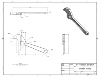
Wrench
- 1. 4 3 2 1 7.60 D D .32 .54 .15 R.15 C C .37 .93 R1.25 R1.00 1.45 R.25 4.16 B .58 .53 B .40 .51 .44 R.42 1.62 4.30 .10 R.48 NOTES: DRAWN FILLETS AROUND THE SQUARE HOLE ARE 0.05 Bryant 3/27/2010 OTHER FILLETS ARE 0.120 CHECKED ITT TECHNICAL INSTITUTE TITLE A QA A MFG WRENCH HANDLE APPROVED SIZE DWG NO REV C SCALE 1:1 SHEET 1 OF 1 4 3 2 1