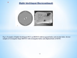
Downloaded 16 times
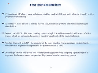
![ Large mode area for the single mode signal allows one to obtain a high power output with
relatively low power density.
Highly efficient lasers ….
Fig7: Double clad PCF (after Limpert et al. [51]). A solid core is surrounded with low filling factor cladding (inner
one), which plays a role of a pump core since the pump field is confined by a second high filling factor cladding
(outer one).
* Fiber lasers and amplifiers (continued)
14](https://image.slidesharecdn.com/whatispcf-190829201559/85/What-is-pcf-14-320.jpg)
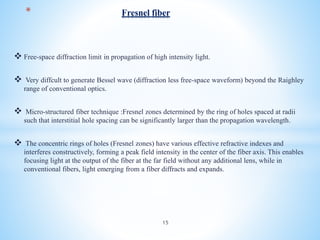

Photonic crystal fiber (PCF) uses a periodic arrangement of air holes in the cladding around a solid core or hollow core to guide light. PCFs offer several advantages over traditional optical fibers, including the ability to design fibers that are endlessly single mode, have zero dispersion in visible wavelengths, and high nonlinearities. They can also be engineered to have special properties like high birefringence, dispersion compensation, large mode areas, and sensing capabilities. Key applications of PCF include telecommunications, fiber lasers, nonlinear devices, high power transmission, and chemical/biological sensing.


