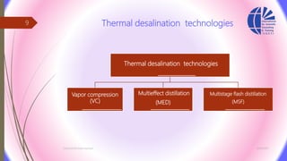
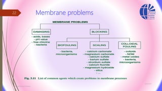
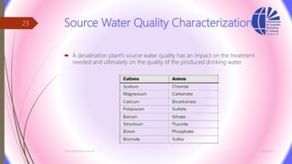
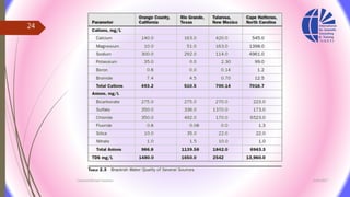
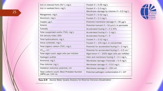
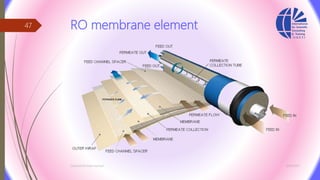
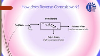
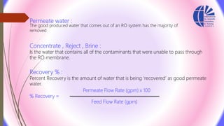
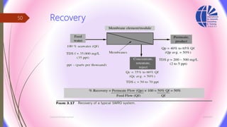
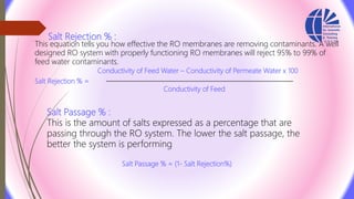
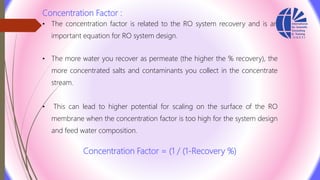
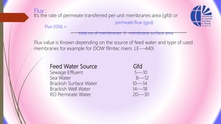
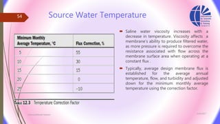
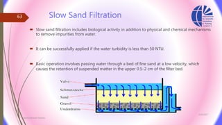
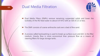
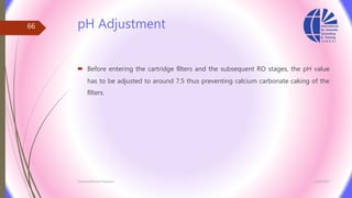
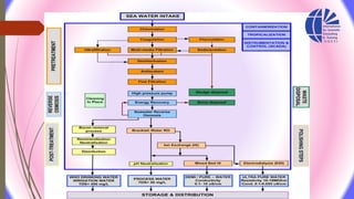
Water Desalination technologies
3/26/2017
1
By/ Ahmed Mohamed Hasham
Water Desalination technologies
3/26/2017
2
https://eg.linkedin.com/in/ahmed-hasham-mmba-01024b27
Chemist / Ahmed Hasham (Hesham) ahmedhasham83@gmail.com
raw water
High pressure
Feed
water
under
pressure
Reject
water
Semi-permeable
membrane
Permeate
water
drain or recycle
Low pressure
Purified water
About the presenter
 Member of the Board scientists Egypt.
 Member of Scientific Professions Syndicate.
 Member of the Arab Society for experts and Safety Professionals.
 Member of the International Association of Engineers.
 Expert of water and waste water treatment technologies.
 Certified trainer in water treatment field .
 Certified trainer in Quality Management Systems field.
 https://eg.linkedin.com/in/ahmed-hasham-mmba-01024b27
 0021159465989
 ahmedhasham83@gmail.com
3/26/2017Chemist/Ahmed Hasham
3
Terminology
 Total dissolved solids: the concentration of which is expressed in milligrams per liter
(mg/L)/ parts per million (ppm) or parts per thousand (ppt).
 thermal distillation: freshwater is separated from the saline source by evaporation.
 Reverse osmosis desalination: freshwater is produced from saline source water by
pressure-driven transport through semipermeable membranes.
3/26/2017
Chemist/Ahmed Hasham
4
 Electrodialysis (ED) : is electrically driven desalination in which salt ions are
removed out of the source water through exposure to direct electric current.
 Ion Exchange (IX) : is the selective removal of salt ions from water by adsorption
onto ion-selective resin media.
3/26/2017Chemist/Ahmed Hasham
5
 Potable water standard:
(US EPA) have established a maximum TDS concentration of 500 mg/L as a potable
water standard.
 Water classification according TDS :
3/26/2017Chemist/Ahmed Hasham
6
Desalination Process Applicability
Separation Process Range of Source Water TDS Conc. for Cost-Effective Application, mg/L
Distillation 20,000–100,000
Reverse osmosis 50–46,000
Electrodialysis 200–3000
Ion exchange 1–800
3/26/2017Chemist/Ahmed Hasham
7
3/26/2017Chemist/Ahmed Hasham
8
Thermal desalination technologies
Vapor compression
(VC)
Multieffect distillation
(MED)
Multistage flash distillation
(MSF)
3/26/2017Chemist/Ahmed Hasham
9
Multistage Flash Distillation
3/26/2017Chemist/Ahmed Hasham
10
Recovery of MSF plant
 The total MSF plant recovery (i.e., the volume of distillate expressed as a
percentage of the total volume of processed source water) is typically 19 to 28
percent.
 For comparison, RO seawater desalination plants have a recovery of 40 to 45
percent.
3/26/2017Chemist/Ahmed Hasham
11
Multiple-Effect Distillation
 In multiple-effect distillation (MED) systems, saline source water is typically not
heated; cold source water is sprayed via nozzles or perforated plates over
bundles of heat exchanger tubes.
 This feed water sprayed on the tube bundles boils, and the generated vapor
passes through mist eliminators, which collect brine droplets from the vapor.
3/26/2017Chemist/Ahmed Hasham
12
Multiple-Effect Distillation
3/26/2017Chemist/Ahmed Hasham
13
 MED desalination systems typically operate at lower temperatures than MSF plants
 The newest MED technologies, which include vertically positioned effects may yield
a GOR of up to 24 kg of potable water per kilogram of steam.
3/26/2017Chemist/Ahmed Hasham
14
Vapor Compression
 The heat source for vapor compression (VC)
systems is compressed vapor produced by a
mechanical compressor or a steam jet
ejector rather than a direct exchange of
heat from steam.
3/26/2017Chemist/Ahmed Hasham
15
Electrodialysis
 In Electrodialysis (ED)–based desalination systems, the separation of minerals and
product water is achieved through the application of direct electric current to the
source water.
3/26/2017
Chemist/Ahmed Hasham
16
Contaminant removal efficiency
3/26/2017Chemist/Ahmed Hasham
18
3/26/2017Chemist/Ahmed Hasham
19
Reverse Osmosis
 Reverse osmosis (RO) is a process where source water contaminants is forced
under pressure through a semipermeable membrane.
 semipermeable membrane : selectively allows water to pass through it at much
higher rate than the transfer rate of any contaminants in the water.
3/26/2017Chemist/Ahmed Hasham
20
3/26/2017Chemist/Ahmed Hasham
21
Membrane problems
3/26/2017
Chemist/Ahmed Hasham
22
Source Water Quality Characterization
 A desalination plant’s source water quality has an impact on the treatment
needed and ultimately on the quality of the produced drinking water.
3/26/2017Chemist/Ahmed Hasham
23
3/26/2017Chemist/Ahmed Hasham
24
3/26/2017Chemist/Ahmed Hasham
25
Total Dissolved Solids TDS
 The TDS of the source water is the most important water quality parameter in RO
desalination for two main reasons:
1. TDS is a main factor in determining the feed pressure.
2. and therefore, the energy needed to produce freshwater from a given saline water
source.
 The ratio between TDS and EC in source water is site specific and usually varies in
a range between 0.67 and 0.70.
 Every 100 mg/L of TDS in the source water creates approximately 0.07 bar of
osmotic pressure
3/26/2017Chemist/Ahmed Hasham
26
 For example, seawater that contains 35,000 mg/L of TDS will create approximately
24.5 bar of osmotic pressure.
 In addition, TDS concentration of the source water is a key factor in determining
the expected product water quality
3/26/2017Chemist/Ahmed Hasham
27
 Besides sodium and chloride, which need to be removed in order to produce
freshwater, other key inorganic constituents of TDS are various minerals (mainly
salts of calcium and magnesium).
 These bivalent salts can precipitate on the surface of the membrane and form a
thin layer of crystalline scale
3/26/2017Chemist/Ahmed Hasham
28
Dissolved Gases
 Both seawater and brackish water often contain various dissolved gases. The most
common gases are oxygen, carbon dioxide, hydrogen sulfide, and ammonia.
 All of these gases pass through RO membranes, and thus desalination is typically
not a suitable technology for degasification.
 The dissolved oxygen concentration of these waters typically varies between 5 and 8
mg/L.
 Groundwater aquifers have a very low oxygen content (0.5 mg/L or less)
3/26/2017Chemist/Ahmed Hasham
29
Particulate Membrane Foulants
 Particulate foulants are organic and inorganic particles contained in the source
water, such as fine debris, plankton, detritus, and silt. These solids cannot pass
through RO membranes.
 Turbidity:
The turbidity level in the source water is indicative of the content of clay, silt,
suspended organic matter, and microscopic aquatic life, such as phyto and
zooplankton. It is expressed in nephelometric turbidity units (NTU).
3/26/2017Chemist/Ahmed Hasham
30
Silt Density Index (SDI)
 Silt density index (SDI) is a parameter that provides an indication of the
particulate fouling potential of source water.
 Particulate membrane fouling will result in a decline of system productivity
(membrane flux) over time.
 and is based on the measurement of the time in seconds it takes to collect a 500-
mL sample through a paper filter of size 0.45 µm and diameter 45 mm
 the source water has flowed through the filter under a driving filtration pressure
of 2.1 bar.
3/26/2017Chemist/Ahmed Hasham
31
Total Suspended Solids
 Total suspended solids (TSS) is measured by filtering a known volume of water
(typically 1 L) through a pre weighed glass-fiber filter, drying the filter with the
solids retained on it at 103 to 105°C, and then weighing the filter again after
drying.
3/26/2017Chemist/Ahmed Hasham
32
Chlorophyll a
 The chlorophyll a concentration of a source water is an indicator of the content of
algae with green pigmentation in the water.
 This parameter is measured using a fluorometer or spectrophotometer.
 It should be pointed out that content of algae and chlorophyll a naturally varies
diurnally and seasonally, and also changes with depth.
 In general, algal content is proportional to the intensity of solar irradiation and
typically increases significantly in the summer, as compared to the average
annual algal content.
3/26/2017Chemist/Ahmed Hasham
33
Colloidal foulants
 Colloidal foulants are inorganic and organic compounds that naturally exist in
suspension and may be concentrated by the RO separation process and
precipitate on the membrane surface, thereby causing membrane flux to decline
over time.
3/26/2017Chemist/Ahmed Hasham
34
Iron and Manganese
 If iron and manganese are in reduced form and they are below 1.0 and 0.1 mg/L,
respectively, they can be removed by RO membranes without causing
accelerated fouling.
 However, if iron and manganese are in oxidized form, their levels should be
reduced below 0.05 and 0.02 mg/L, respectively, to prevent mineral fouling of the
membranes.
3/26/2017Chemist/Ahmed Hasham
35
Silica
 Total silica (silicon dioxide) in the source water consists of reactive silica, which is
in soluble form, and unreactive silica, which is in colloidal form.
 While reactive silica is not a challenge for RO membranes, colloidal silica in the
saline source water can cause significant membrane fouling.
3/26/2017Chemist/Ahmed Hasham
36
3/26/2017Chemist/Ahmed Hasham
37
Natural Organic Foulants
 Natural organic foulants :
This NOM is easily biodegradable and provides a food source for biogrowth of bacteria
on the RO membrane.
 Microbiological foulants (biofoulants):
The phenomenon of accumulation of aquatic organisms and their metabolic products
on the membrane surface is known as biological fouling or biofouling.
3/26/2017Chemist/Ahmed Hasham
38
Total Organic Carbon
 Total organic carbon (TOC) is one of the most widely used measures for the
organic content of saline source water.
 TOC concentration measures the content of both NOM and easily biodegradable
organics, such as polysaccharides, released during algal blooms.
3/26/2017Chemist/Ahmed Hasham
39
UV254 Absorbance
 UV254 The ultraviolet (UV) absorbance of a seawater sample at 254 nm is an
indirect measure of NOM.
 The UV absorbance of a saline water sample is determined by filtering the
sample through a 0.45-µm filter and measuring the filtrate’s absorbance of UV
with a spectrophotometer.
 Specific UV absorbance (SUVA) is defined as the UV absorbance divided by the
concentration of dissolved organic carbon in the source water.
3/26/2017Chemist/Ahmed Hasham
40
3/26/2017Chemist/Ahmed Hasham
41
3/26/2017Chemist/Ahmed Hasham
42
Reverse Osmosis Membrane Structures, and Materials
3/26/2017
Chemist/Ahmed Hasham
43
3/26/2017
Chemist/Ahmed Hasham
44
Separation spectrum of pressure-driven membrane
processes
3/26/2017Chemist/Ahmed Hasham
45
RO membrane element
3/26/2017Chemist/Ahmed Hasham
46
RO membrane element
3/26/2017Chemist/Ahmed Hasham
47
How does Reverse Osmosis work?
Permeate water :
The good produced water that comes out of an RO system has the majority of
removed
Concentrate , Reject , Brine :
Is the water that contains all of the contaminants that were unable to pass through
the RO membrane.
Recovery % :
Percent Recovery is the amount of water that is being ‘recovered’ as good permeate
water.
Permeate Flow Rate (gpm) x 100
% Recovery =
Feed Flow Rate (gpm)
Recovery
3/26/2017Chemist/Ahmed Hasham
50
Salt Rejection % :
This equation tells you how effective the RO membranes are removing contaminants. A well
designed RO system with properly functioning RO membranes will reject 95% to 99% of
feed water contaminants.
Conductivity of Feed Water – Conductivity of Permeate Water x 100
Salt Rejection % =
Conductivity of Feed
Salt Passage % :
This is the amount of salts expressed as a percentage that are
passing through the RO system. The lower the salt passage, the
better the system is performing
Salt Passage % = (1‐ Salt Rejection%)
Concentration Factor :
• The concentration factor is related to the RO system recovery and is an
important equation for RO system design.
• The more water you recover as permeate (the higher the % recovery), the
more concentrated salts and contaminants you collect in the concentrate
stream.
• This can lead to higher potential for scaling on the surface of the RO
membrane when the concentration factor is too high for the system design
and feed water composition.
Concentration Factor = (1 / (1‐Recovery %)
Flux :
It’s the rate of permeate transferred per unit membranes area (gfd) or
permeate flow (gpd)
Flux (Gfd) =
total no of membranes X membrane surface area
Flux value is Known depending on the source of feed water and type of used
membranes for example for DOW filmtec mem. LE--‐440i
Feed Water Source Gfd
Sewage Effluent 5--‐10
Sea Water 8--‐12
Brackish Surface Water 10--‐14
Brackish Well Water 14--‐18
RO Permeate Water 20--‐30
Source Water Temperature
 Saline water viscosity increases with a
decrease in temperature. Viscosity affects a
membrane’s ability to produce filtered water,
as more pressure is required to overcome the
resistance associated with flow across the
membrane surface area when operating at a
constant flux .
 Typically, average design membrane flux is
established for the average annual
temperature, flow, and turbidity and adjusted
down for the minimum monthly average
temperature using the correction factor.
3/26/2017
Chemist/Ahmed Hasham
54
Pretreatment
 The purpose of the first step source water pretreatment is to remove the
suspended solids and prevent some of the naturally occurring soluble solids from
turning into solid form and precipitating on the RO membranes during the salt
separation process.
3/26/2017Chemist/Ahmed Hasham
55
RO system
 The second step the RO system separates the dissolved solids
from the pretreated source water, thereby producing fresh low-
salinity water suitable for human consumption, agricultural uses, and
for industrial and other applications.
 The key components of the RO separation system include filter
effluent transfer pumps , high-pressure pumps, reverse osmosis
trains, energy recovery equipment, and the membrane cleaning
system.
3/26/2017Chemist/Ahmed Hasham
56
post-treatment
 The third step of the desalination plant treatment process is referred to as post-
treatment once the desalination process is complete, the freshwater produced by
the RO system is further treated for corrosion and health protection and
disinfected prior to distribution for final use.
3/26/2017Chemist/Ahmed Hasham
57
Diagram of a conventional pretreatment process
3/26/2017
Chemist/Ahmed Hasham
58
Disadvantages of conventional pretreatment
 fluctuations of feed water quality
 difficulties in supplying a constant SDI < 3.0
 difficulties in removing particles smaller than 10–15 µm
 large space occupation due to slow filtration velocities
3/26/2017Chemist/Ahmed Hasham
59
Screens
 Screens are used to protect water pumps from clogging and to remove coarse
floating solids from feed water.
 The screens can be located onshore, or at the end of a channel that extends out
beyond the surf zone, or at the end of a pipe that extends out into the sea,
terminating in a vertical “velocity cap”
3/26/2017Chemist/Ahmed Hasham
60
Chlorination
 Chlorination is a basic disinfection method aimed at destroying or inactivating
pathogenic microorganisms including bacteria, amoebic cysts, algae, spores and
viruses.
 Or
3/26/2017Chemist/Ahmed Hasham
61
Coagulation and Flocculation
 Coagulation is applied to remove the fine suspended solids that fail to settle
during the sedimentation process, as well as soluble organic and toxic
substances, and trace metals (size range of 1 nm to 1.0 µm)
3/26/2017Chemist/Ahmed Hasham
62
Slow Sand Filtration
 Slow sand filtration includes biological activity in addition to physical and chemical mechanisms
to remove impurities from water.
 It can be successfully applied if the water turbidity is less than 50 NTU.
 Basic operation involves passing water through a bed of fine sand at a low velocity, which
causes the retention of suspended matter in the upper 0.5–2 cm of the filter bed.
3/26/2017
Chemist/Ahmed Hasham
63
Dual Media Filtration
 Dual Media Filters (DMFs) remove remaining suspended solids and lower the
turbidity of the RO feed water to about 0.4 NTU with an SDI of 2.5 or less.
 The DMF consists of coarse anthracite coal over a bed of fine sand .
 A process called backwashing is used to break up surface scum and dirt in the filter
medium. Gravity flow is more economical than pressure flow as a means of
cleaning filters for large storage tanks.
3/26/2017Chemist/Ahmed Hasham
64
3/26/2017Chemist/Ahmed Hasham
65
pH Adjustment
 Before entering the cartridge filters and the subsequent RO stages, the pH value
has to be adjusted to around 7.5 thus preventing calcium carbonate caking of the
filters.
3/26/2017Chemist/Ahmed Hasham
66
Anti-scaling Agents
 The addition of anti-scaling agents is advisable for seawater RO systems that
work with recoveries greater than 35% .
 anti-scalant such as polyphosphates and polyacrylates widely used.
3/26/2017Chemist/Ahmed Hasham
67
Dechlorination
 Dechlorination has to be performed prior to the RO stage in order to avoid
oxidation damage by residual chlorine in the feed water.
 Commonly, sodium metabisulphite is used for dechlorination due its high cost
effectiveness.
3/26/2017Chemist/Ahmed Hasham
68
Cartridge Filters
 Cartridge filters are preferred systems for low water contamination.
 Usual pore size ranges from 5 to 10 µm.
3/26/2017Chemist/Ahmed Hasham
69
MF/UF Pretreatment
 Microfiltration is a low energy-consuming technique extensively used to remove
suspended solids and to lower COD/BOD and SDI to values below 5.
 the UF membrane separation method remains economically competitive compared to
conventional pretreatments.
 Turbidity is also greatly decreased, and SDI is always below 2 .
3/26/2017Chemist/Ahmed Hasham
70
Intake
3/26/2017Chemist/Ahmed Hasham
71
3/26/2017Chemist/Ahmed Hasham
72
Energy use
3/26/2017Chemist/Ahmed Hasham
73
Chemicals Commonly Used in Desalination Plants
3/26/2017Chemist/Ahmed Hasham
74
Relationship between plant size and cost of water production.
3/26/2017
Chemist/Ahmed Hasham
75
Target Minimum Pretreated Water Quality
3/26/2017Chemist/Ahmed Hasham
76
Filter Media Backwash
 Granular media filters are typically backwashed using filtered source water or
concentrate from the RO membrane system.
 The backwash frequency of filter cells is usually once every 24 to 48 h.
 The uniformity coefficient is an important parameter because it indicates how
similar the media particles are in size. In general, for media of the same size, a
higher uniformity coefficient allows for an increased filter cycle length.
3/26/2017Chemist/Ahmed Hasham
77
uniformity coefficient
3/26/2017Chemist/Ahmed Hasham
78
Direct flow-through desalination system
3/26/2017Chemist/Ahmed Hasham
79
passes and stages in a Reverse Osmosis (RO) system
References
 Handbook of Industrial and Hazardous Wastes Treatment -Lawrence K.Wang ,et.al.
 Seawater Desalination , Conventional and Renewable Energy Processes. Andrea
Cipollina , et.al.
3/26/2017Chemist/Ahmed Hasham
83
 ahmedhasham83@gmail.com
 Isct.Egypt@gmail.com
 https://www.facebook.com/isct.site/
 00201159465989
 00201146139692
3/26/2017Chemist/Ahmed Hasham
84
https://eg.linkedin.com/in/ahmed-hasham-mmba-01024b27

Water Desalination Technology

  • 1.
  • 2.
    Water Desalination technologies 3/26/2017 2 https://eg.linkedin.com/in/ahmed-hasham-mmba-01024b27 Chemist/ Ahmed Hasham (Hesham) ahmedhasham83@gmail.com raw water High pressure Feed water under pressure Reject water Semi-permeable membrane Permeate water drain or recycle Low pressure Purified water
  • 3.
    About the presenter Member of the Board scientists Egypt.  Member of Scientific Professions Syndicate.  Member of the Arab Society for experts and Safety Professionals.  Member of the International Association of Engineers.  Expert of water and waste water treatment technologies.  Certified trainer in water treatment field .  Certified trainer in Quality Management Systems field.  https://eg.linkedin.com/in/ahmed-hasham-mmba-01024b27  0021159465989  ahmedhasham83@gmail.com 3/26/2017Chemist/Ahmed Hasham 3
  • 4.
    Terminology  Total dissolvedsolids: the concentration of which is expressed in milligrams per liter (mg/L)/ parts per million (ppm) or parts per thousand (ppt).  thermal distillation: freshwater is separated from the saline source by evaporation.  Reverse osmosis desalination: freshwater is produced from saline source water by pressure-driven transport through semipermeable membranes. 3/26/2017 Chemist/Ahmed Hasham 4
  • 5.
     Electrodialysis (ED): is electrically driven desalination in which salt ions are removed out of the source water through exposure to direct electric current.  Ion Exchange (IX) : is the selective removal of salt ions from water by adsorption onto ion-selective resin media. 3/26/2017Chemist/Ahmed Hasham 5
  • 6.
     Potable waterstandard: (US EPA) have established a maximum TDS concentration of 500 mg/L as a potable water standard.  Water classification according TDS : 3/26/2017Chemist/Ahmed Hasham 6
  • 7.
    Desalination Process Applicability SeparationProcess Range of Source Water TDS Conc. for Cost-Effective Application, mg/L Distillation 20,000–100,000 Reverse osmosis 50–46,000 Electrodialysis 200–3000 Ion exchange 1–800 3/26/2017Chemist/Ahmed Hasham 7
  • 8.
  • 9.
    Thermal desalination technologies Thermaldesalination technologies Vapor compression (VC) Multieffect distillation (MED) Multistage flash distillation (MSF) 3/26/2017Chemist/Ahmed Hasham 9
  • 10.
  • 11.
    Recovery of MSFplant  The total MSF plant recovery (i.e., the volume of distillate expressed as a percentage of the total volume of processed source water) is typically 19 to 28 percent.  For comparison, RO seawater desalination plants have a recovery of 40 to 45 percent. 3/26/2017Chemist/Ahmed Hasham 11
  • 12.
    Multiple-Effect Distillation  Inmultiple-effect distillation (MED) systems, saline source water is typically not heated; cold source water is sprayed via nozzles or perforated plates over bundles of heat exchanger tubes.  This feed water sprayed on the tube bundles boils, and the generated vapor passes through mist eliminators, which collect brine droplets from the vapor. 3/26/2017Chemist/Ahmed Hasham 12
  • 13.
  • 14.
     MED desalinationsystems typically operate at lower temperatures than MSF plants  The newest MED technologies, which include vertically positioned effects may yield a GOR of up to 24 kg of potable water per kilogram of steam. 3/26/2017Chemist/Ahmed Hasham 14
  • 15.
    Vapor Compression  Theheat source for vapor compression (VC) systems is compressed vapor produced by a mechanical compressor or a steam jet ejector rather than a direct exchange of heat from steam. 3/26/2017Chemist/Ahmed Hasham 15
  • 16.
    Electrodialysis  In Electrodialysis(ED)–based desalination systems, the separation of minerals and product water is achieved through the application of direct electric current to the source water. 3/26/2017 Chemist/Ahmed Hasham 16
  • 18.
  • 19.
  • 20.
    Reverse Osmosis  Reverseosmosis (RO) is a process where source water contaminants is forced under pressure through a semipermeable membrane.  semipermeable membrane : selectively allows water to pass through it at much higher rate than the transfer rate of any contaminants in the water. 3/26/2017Chemist/Ahmed Hasham 20
  • 21.
  • 22.
  • 23.
    Source Water QualityCharacterization  A desalination plant’s source water quality has an impact on the treatment needed and ultimately on the quality of the produced drinking water. 3/26/2017Chemist/Ahmed Hasham 23
  • 24.
  • 25.
  • 26.
    Total Dissolved SolidsTDS  The TDS of the source water is the most important water quality parameter in RO desalination for two main reasons: 1. TDS is a main factor in determining the feed pressure. 2. and therefore, the energy needed to produce freshwater from a given saline water source.  The ratio between TDS and EC in source water is site specific and usually varies in a range between 0.67 and 0.70.  Every 100 mg/L of TDS in the source water creates approximately 0.07 bar of osmotic pressure 3/26/2017Chemist/Ahmed Hasham 26
  • 27.
     For example,seawater that contains 35,000 mg/L of TDS will create approximately 24.5 bar of osmotic pressure.  In addition, TDS concentration of the source water is a key factor in determining the expected product water quality 3/26/2017Chemist/Ahmed Hasham 27
  • 28.
     Besides sodiumand chloride, which need to be removed in order to produce freshwater, other key inorganic constituents of TDS are various minerals (mainly salts of calcium and magnesium).  These bivalent salts can precipitate on the surface of the membrane and form a thin layer of crystalline scale 3/26/2017Chemist/Ahmed Hasham 28
  • 29.
    Dissolved Gases  Bothseawater and brackish water often contain various dissolved gases. The most common gases are oxygen, carbon dioxide, hydrogen sulfide, and ammonia.  All of these gases pass through RO membranes, and thus desalination is typically not a suitable technology for degasification.  The dissolved oxygen concentration of these waters typically varies between 5 and 8 mg/L.  Groundwater aquifers have a very low oxygen content (0.5 mg/L or less) 3/26/2017Chemist/Ahmed Hasham 29
  • 30.
    Particulate Membrane Foulants Particulate foulants are organic and inorganic particles contained in the source water, such as fine debris, plankton, detritus, and silt. These solids cannot pass through RO membranes.  Turbidity: The turbidity level in the source water is indicative of the content of clay, silt, suspended organic matter, and microscopic aquatic life, such as phyto and zooplankton. It is expressed in nephelometric turbidity units (NTU). 3/26/2017Chemist/Ahmed Hasham 30
  • 31.
    Silt Density Index(SDI)  Silt density index (SDI) is a parameter that provides an indication of the particulate fouling potential of source water.  Particulate membrane fouling will result in a decline of system productivity (membrane flux) over time.  and is based on the measurement of the time in seconds it takes to collect a 500- mL sample through a paper filter of size 0.45 µm and diameter 45 mm  the source water has flowed through the filter under a driving filtration pressure of 2.1 bar. 3/26/2017Chemist/Ahmed Hasham 31
  • 32.
    Total Suspended Solids Total suspended solids (TSS) is measured by filtering a known volume of water (typically 1 L) through a pre weighed glass-fiber filter, drying the filter with the solids retained on it at 103 to 105°C, and then weighing the filter again after drying. 3/26/2017Chemist/Ahmed Hasham 32
  • 33.
    Chlorophyll a  Thechlorophyll a concentration of a source water is an indicator of the content of algae with green pigmentation in the water.  This parameter is measured using a fluorometer or spectrophotometer.  It should be pointed out that content of algae and chlorophyll a naturally varies diurnally and seasonally, and also changes with depth.  In general, algal content is proportional to the intensity of solar irradiation and typically increases significantly in the summer, as compared to the average annual algal content. 3/26/2017Chemist/Ahmed Hasham 33
  • 34.
    Colloidal foulants  Colloidalfoulants are inorganic and organic compounds that naturally exist in suspension and may be concentrated by the RO separation process and precipitate on the membrane surface, thereby causing membrane flux to decline over time. 3/26/2017Chemist/Ahmed Hasham 34
  • 35.
    Iron and Manganese If iron and manganese are in reduced form and they are below 1.0 and 0.1 mg/L, respectively, they can be removed by RO membranes without causing accelerated fouling.  However, if iron and manganese are in oxidized form, their levels should be reduced below 0.05 and 0.02 mg/L, respectively, to prevent mineral fouling of the membranes. 3/26/2017Chemist/Ahmed Hasham 35
  • 36.
    Silica  Total silica(silicon dioxide) in the source water consists of reactive silica, which is in soluble form, and unreactive silica, which is in colloidal form.  While reactive silica is not a challenge for RO membranes, colloidal silica in the saline source water can cause significant membrane fouling. 3/26/2017Chemist/Ahmed Hasham 36
  • 37.
  • 38.
    Natural Organic Foulants Natural organic foulants : This NOM is easily biodegradable and provides a food source for biogrowth of bacteria on the RO membrane.  Microbiological foulants (biofoulants): The phenomenon of accumulation of aquatic organisms and their metabolic products on the membrane surface is known as biological fouling or biofouling. 3/26/2017Chemist/Ahmed Hasham 38
  • 39.
    Total Organic Carbon Total organic carbon (TOC) is one of the most widely used measures for the organic content of saline source water.  TOC concentration measures the content of both NOM and easily biodegradable organics, such as polysaccharides, released during algal blooms. 3/26/2017Chemist/Ahmed Hasham 39
  • 40.
    UV254 Absorbance  UV254The ultraviolet (UV) absorbance of a seawater sample at 254 nm is an indirect measure of NOM.  The UV absorbance of a saline water sample is determined by filtering the sample through a 0.45-µm filter and measuring the filtrate’s absorbance of UV with a spectrophotometer.  Specific UV absorbance (SUVA) is defined as the UV absorbance divided by the concentration of dissolved organic carbon in the source water. 3/26/2017Chemist/Ahmed Hasham 40
  • 41.
  • 42.
  • 43.
    Reverse Osmosis MembraneStructures, and Materials 3/26/2017 Chemist/Ahmed Hasham 43
  • 44.
  • 45.
    Separation spectrum ofpressure-driven membrane processes 3/26/2017Chemist/Ahmed Hasham 45
  • 46.
  • 47.
  • 48.
    How does ReverseOsmosis work?
  • 49.
    Permeate water : Thegood produced water that comes out of an RO system has the majority of removed Concentrate , Reject , Brine : Is the water that contains all of the contaminants that were unable to pass through the RO membrane. Recovery % : Percent Recovery is the amount of water that is being ‘recovered’ as good permeate water. Permeate Flow Rate (gpm) x 100 % Recovery = Feed Flow Rate (gpm)
  • 50.
  • 51.
    Salt Rejection %: This equation tells you how effective the RO membranes are removing contaminants. A well designed RO system with properly functioning RO membranes will reject 95% to 99% of feed water contaminants. Conductivity of Feed Water – Conductivity of Permeate Water x 100 Salt Rejection % = Conductivity of Feed Salt Passage % : This is the amount of salts expressed as a percentage that are passing through the RO system. The lower the salt passage, the better the system is performing Salt Passage % = (1‐ Salt Rejection%)
  • 52.
    Concentration Factor : •The concentration factor is related to the RO system recovery and is an important equation for RO system design. • The more water you recover as permeate (the higher the % recovery), the more concentrated salts and contaminants you collect in the concentrate stream. • This can lead to higher potential for scaling on the surface of the RO membrane when the concentration factor is too high for the system design and feed water composition. Concentration Factor = (1 / (1‐Recovery %)
  • 53.
    Flux : It’s therate of permeate transferred per unit membranes area (gfd) or permeate flow (gpd) Flux (Gfd) = total no of membranes X membrane surface area Flux value is Known depending on the source of feed water and type of used membranes for example for DOW filmtec mem. LE--‐440i Feed Water Source Gfd Sewage Effluent 5--‐10 Sea Water 8--‐12 Brackish Surface Water 10--‐14 Brackish Well Water 14--‐18 RO Permeate Water 20--‐30
  • 54.
    Source Water Temperature Saline water viscosity increases with a decrease in temperature. Viscosity affects a membrane’s ability to produce filtered water, as more pressure is required to overcome the resistance associated with flow across the membrane surface area when operating at a constant flux .  Typically, average design membrane flux is established for the average annual temperature, flow, and turbidity and adjusted down for the minimum monthly average temperature using the correction factor. 3/26/2017 Chemist/Ahmed Hasham 54
  • 55.
    Pretreatment  The purposeof the first step source water pretreatment is to remove the suspended solids and prevent some of the naturally occurring soluble solids from turning into solid form and precipitating on the RO membranes during the salt separation process. 3/26/2017Chemist/Ahmed Hasham 55
  • 56.
    RO system  Thesecond step the RO system separates the dissolved solids from the pretreated source water, thereby producing fresh low- salinity water suitable for human consumption, agricultural uses, and for industrial and other applications.  The key components of the RO separation system include filter effluent transfer pumps , high-pressure pumps, reverse osmosis trains, energy recovery equipment, and the membrane cleaning system. 3/26/2017Chemist/Ahmed Hasham 56
  • 57.
    post-treatment  The thirdstep of the desalination plant treatment process is referred to as post- treatment once the desalination process is complete, the freshwater produced by the RO system is further treated for corrosion and health protection and disinfected prior to distribution for final use. 3/26/2017Chemist/Ahmed Hasham 57
  • 58.
    Diagram of aconventional pretreatment process 3/26/2017 Chemist/Ahmed Hasham 58
  • 59.
    Disadvantages of conventionalpretreatment  fluctuations of feed water quality  difficulties in supplying a constant SDI < 3.0  difficulties in removing particles smaller than 10–15 µm  large space occupation due to slow filtration velocities 3/26/2017Chemist/Ahmed Hasham 59
  • 60.
    Screens  Screens areused to protect water pumps from clogging and to remove coarse floating solids from feed water.  The screens can be located onshore, or at the end of a channel that extends out beyond the surf zone, or at the end of a pipe that extends out into the sea, terminating in a vertical “velocity cap” 3/26/2017Chemist/Ahmed Hasham 60
  • 61.
    Chlorination  Chlorination isa basic disinfection method aimed at destroying or inactivating pathogenic microorganisms including bacteria, amoebic cysts, algae, spores and viruses.  Or 3/26/2017Chemist/Ahmed Hasham 61
  • 62.
    Coagulation and Flocculation Coagulation is applied to remove the fine suspended solids that fail to settle during the sedimentation process, as well as soluble organic and toxic substances, and trace metals (size range of 1 nm to 1.0 µm) 3/26/2017Chemist/Ahmed Hasham 62
  • 63.
    Slow Sand Filtration Slow sand filtration includes biological activity in addition to physical and chemical mechanisms to remove impurities from water.  It can be successfully applied if the water turbidity is less than 50 NTU.  Basic operation involves passing water through a bed of fine sand at a low velocity, which causes the retention of suspended matter in the upper 0.5–2 cm of the filter bed. 3/26/2017 Chemist/Ahmed Hasham 63
  • 64.
    Dual Media Filtration Dual Media Filters (DMFs) remove remaining suspended solids and lower the turbidity of the RO feed water to about 0.4 NTU with an SDI of 2.5 or less.  The DMF consists of coarse anthracite coal over a bed of fine sand .  A process called backwashing is used to break up surface scum and dirt in the filter medium. Gravity flow is more economical than pressure flow as a means of cleaning filters for large storage tanks. 3/26/2017Chemist/Ahmed Hasham 64
  • 65.
  • 66.
    pH Adjustment  Beforeentering the cartridge filters and the subsequent RO stages, the pH value has to be adjusted to around 7.5 thus preventing calcium carbonate caking of the filters. 3/26/2017Chemist/Ahmed Hasham 66
  • 67.
    Anti-scaling Agents  Theaddition of anti-scaling agents is advisable for seawater RO systems that work with recoveries greater than 35% .  anti-scalant such as polyphosphates and polyacrylates widely used. 3/26/2017Chemist/Ahmed Hasham 67
  • 68.
    Dechlorination  Dechlorination hasto be performed prior to the RO stage in order to avoid oxidation damage by residual chlorine in the feed water.  Commonly, sodium metabisulphite is used for dechlorination due its high cost effectiveness. 3/26/2017Chemist/Ahmed Hasham 68
  • 69.
    Cartridge Filters  Cartridgefilters are preferred systems for low water contamination.  Usual pore size ranges from 5 to 10 µm. 3/26/2017Chemist/Ahmed Hasham 69
  • 70.
    MF/UF Pretreatment  Microfiltrationis a low energy-consuming technique extensively used to remove suspended solids and to lower COD/BOD and SDI to values below 5.  the UF membrane separation method remains economically competitive compared to conventional pretreatments.  Turbidity is also greatly decreased, and SDI is always below 2 . 3/26/2017Chemist/Ahmed Hasham 70
  • 71.
  • 72.
  • 73.
  • 74.
    Chemicals Commonly Usedin Desalination Plants 3/26/2017Chemist/Ahmed Hasham 74
  • 75.
    Relationship between plantsize and cost of water production. 3/26/2017 Chemist/Ahmed Hasham 75
  • 76.
    Target Minimum PretreatedWater Quality 3/26/2017Chemist/Ahmed Hasham 76
  • 77.
    Filter Media Backwash Granular media filters are typically backwashed using filtered source water or concentrate from the RO membrane system.  The backwash frequency of filter cells is usually once every 24 to 48 h.  The uniformity coefficient is an important parameter because it indicates how similar the media particles are in size. In general, for media of the same size, a higher uniformity coefficient allows for an increased filter cycle length. 3/26/2017Chemist/Ahmed Hasham 77
  • 78.
  • 79.
    Direct flow-through desalinationsystem 3/26/2017Chemist/Ahmed Hasham 79
  • 80.
    passes and stagesin a Reverse Osmosis (RO) system
  • 83.
    References  Handbook ofIndustrial and Hazardous Wastes Treatment -Lawrence K.Wang ,et.al.  Seawater Desalination , Conventional and Renewable Energy Processes. Andrea Cipollina , et.al. 3/26/2017Chemist/Ahmed Hasham 83
  • 84.
     ahmedhasham83@gmail.com  Isct.Egypt@gmail.com https://www.facebook.com/isct.site/  00201159465989  00201146139692 3/26/2017Chemist/Ahmed Hasham 84 https://eg.linkedin.com/in/ahmed-hasham-mmba-01024b27