Visible light communication (VLC) uses visible light spectrum between 390-750nm for data transmission. It can provide huge bandwidth for multi-gigabit data rates. VLC systems consist of LED lights that act as transmitters and photodiodes as receivers. Common modulation techniques for VLC include on-off keying and pulse-based modulations. VLC provides advantages like unlimited bandwidth, low power consumption, security and indoor positioning. Challenges include flicker mitigation and multipath interference. Standards like IEEE 802.15.7 specify the physical and MAC layers to address these challenges.
An overview of Visible Light Communication (VLC) systems, including contents to be covered.
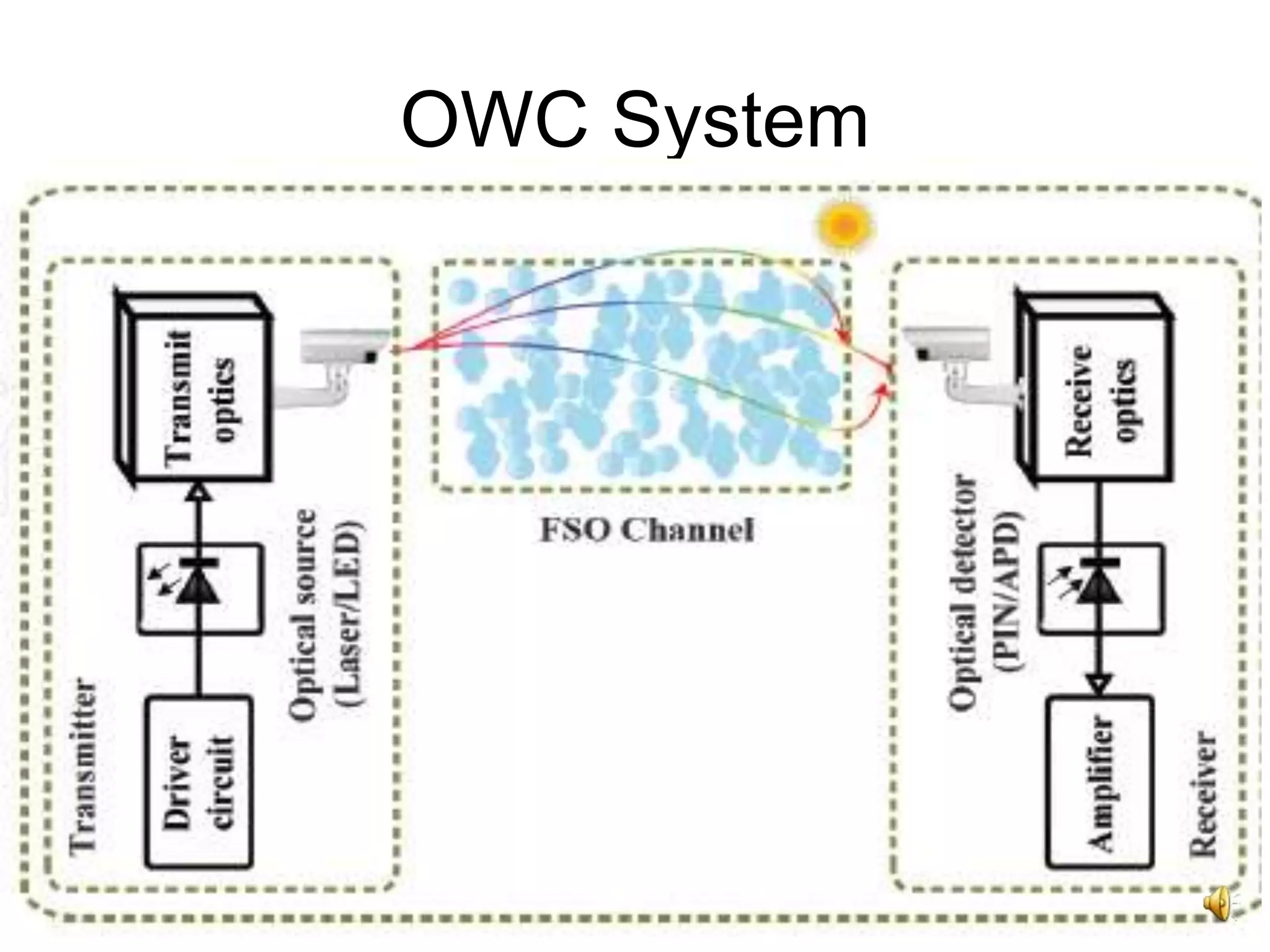
Discusses OWC systems, classifications (indoor and outdoor), capabilities, and FSO communication.
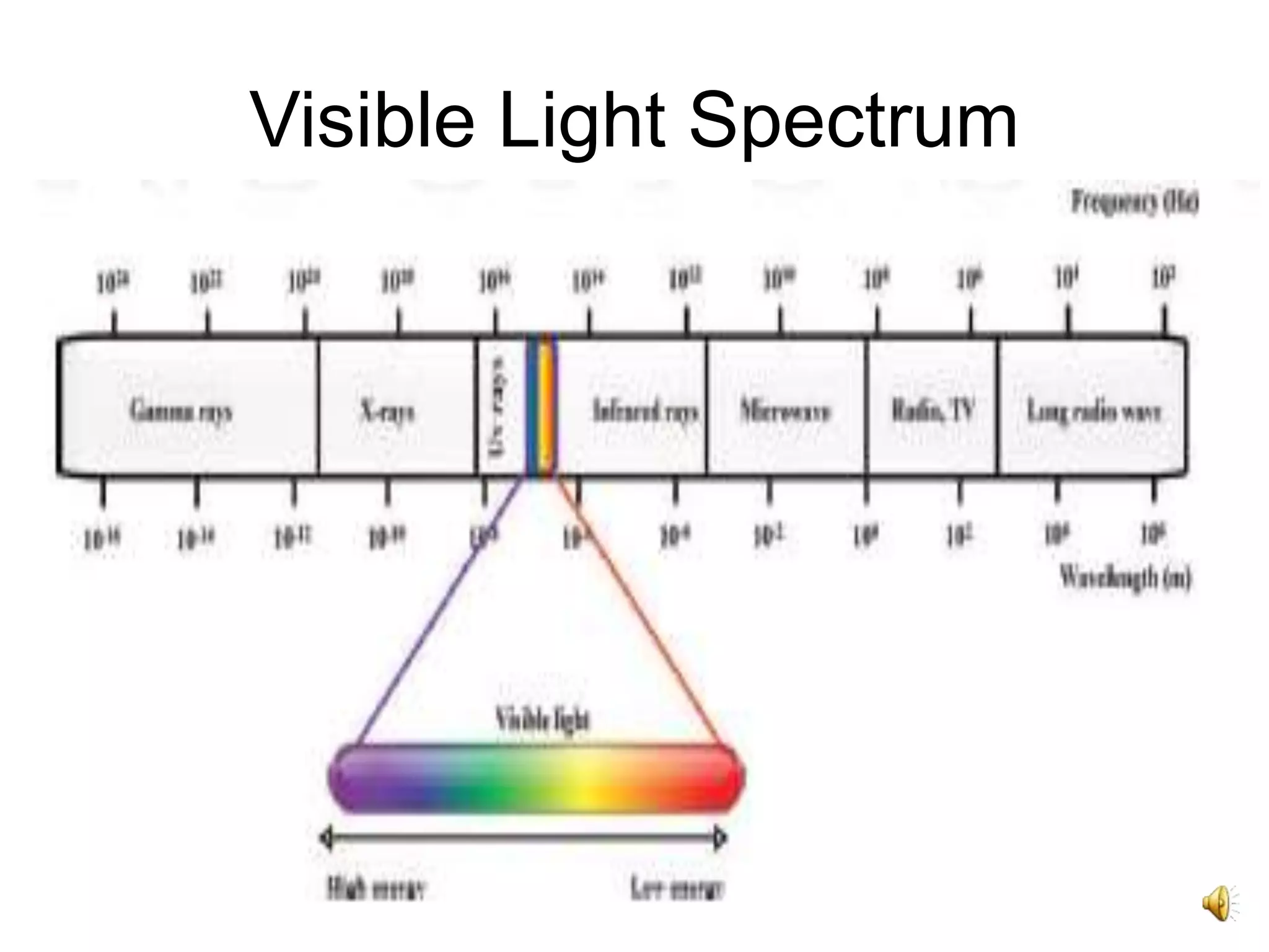
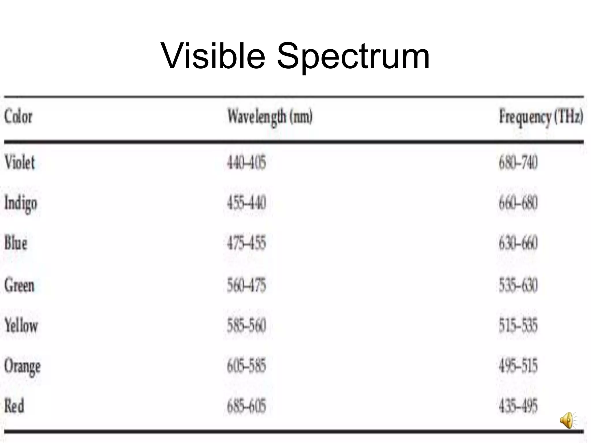
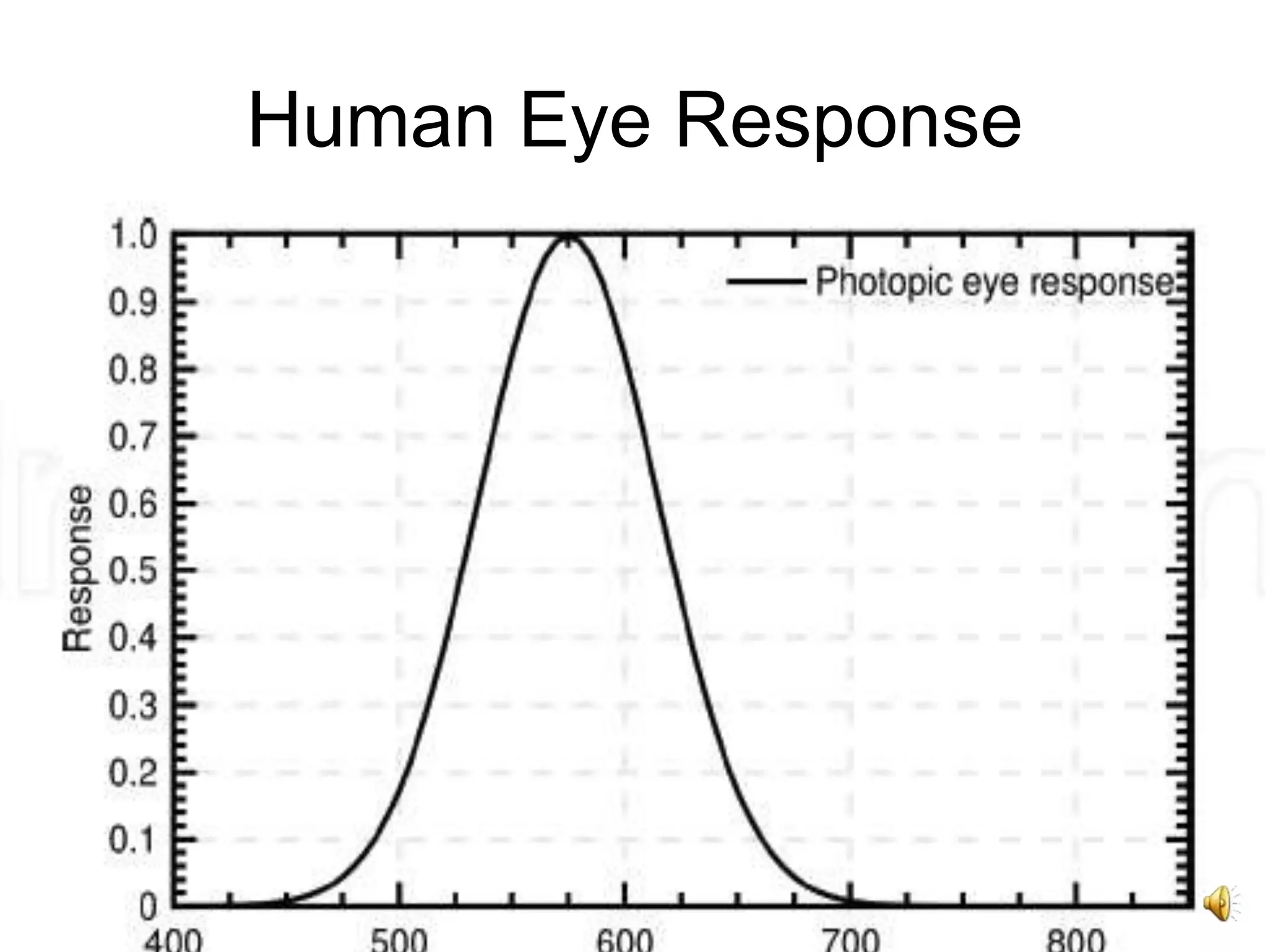
Explores the visible light spectrum and how the human eye perceives different wavelengths.
Details on wavelength ranges used in OWC, transmission windows and their advantages in communications.
Highlights VLC's energy efficiency, band usage, applications in sensitive environments, and accuracy in navigation.
Technologies used in VLC transmission including LEDs, lasers, and RGB LEDs for optimal performance.
Discusses the components of VLC receivers, including photodiodes, optical filters, and issues like interference.
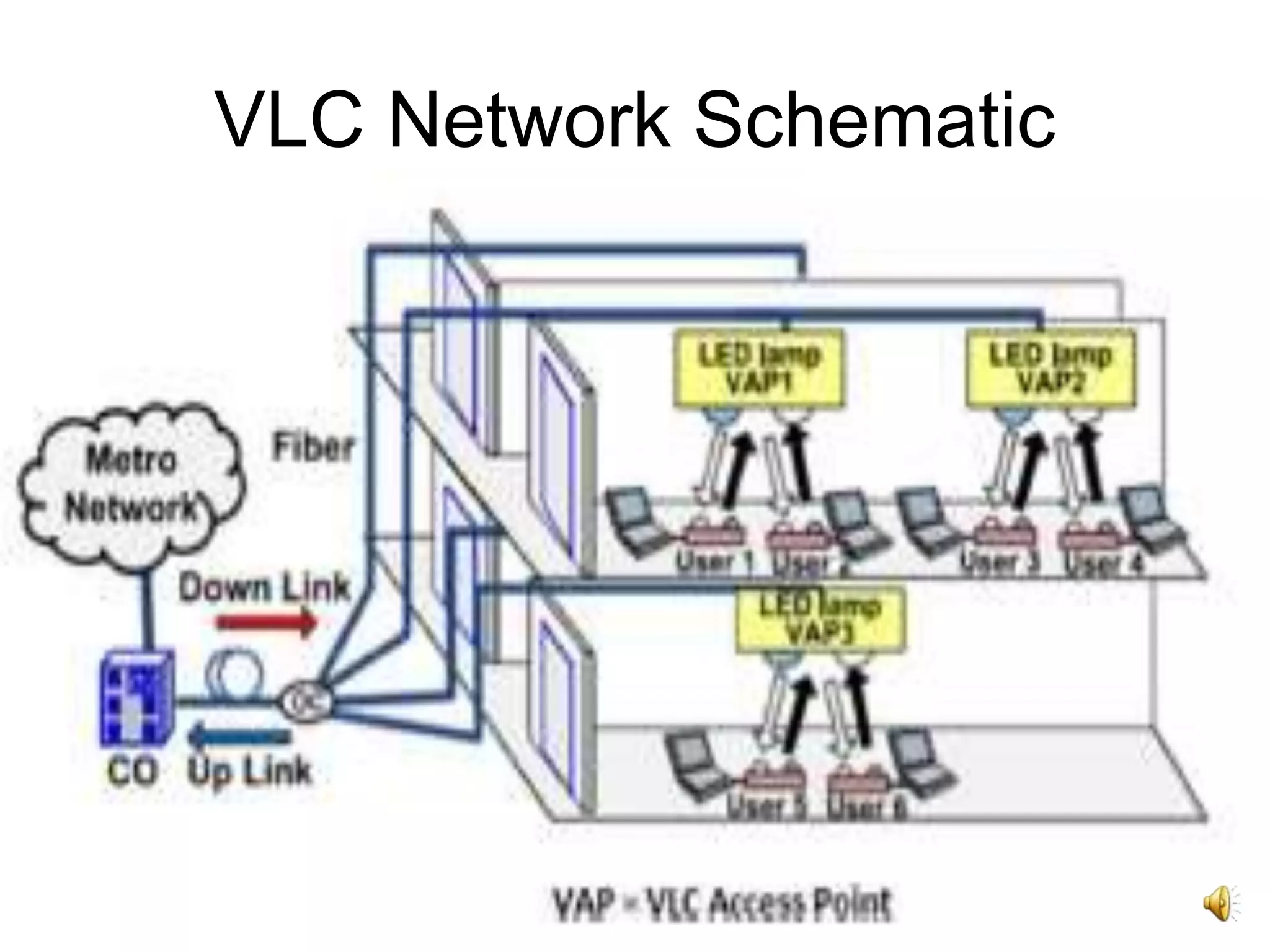
Schematic overview of VLC networks and layered architecture model indicating IEEE standards.Explanation of physical layer specifications, modulation methodologies, and their implications for data rates.
Exploration of On-Off Keying and various pulse modulation techniques and their effectiveness.
Introduces Color Shift Keying and its basis on chromaticity to enhance data rates.
Enumerates key advantages of VLC including bandwidth, low power consumption, security, and ecological benefits.
Identifies challenges such as flicker mitigation, path losses, and interference issues which impact performance.
Discusses standards developed by VLCC and IEEE to address challenges and ensure compliance for future VLC.
Indicates that the presentation will continue with further information on VLC and its applications.
2
Contents
• OWC SystemClassifications.
• Visible Spectrum.
• Introduction and Working Principle.
• VLC Block Diagram.
• Layer Model and Standards.
• Modulation Schemes.
• Advantages and Disadvantages.
• VLC Challenges.
3.
3
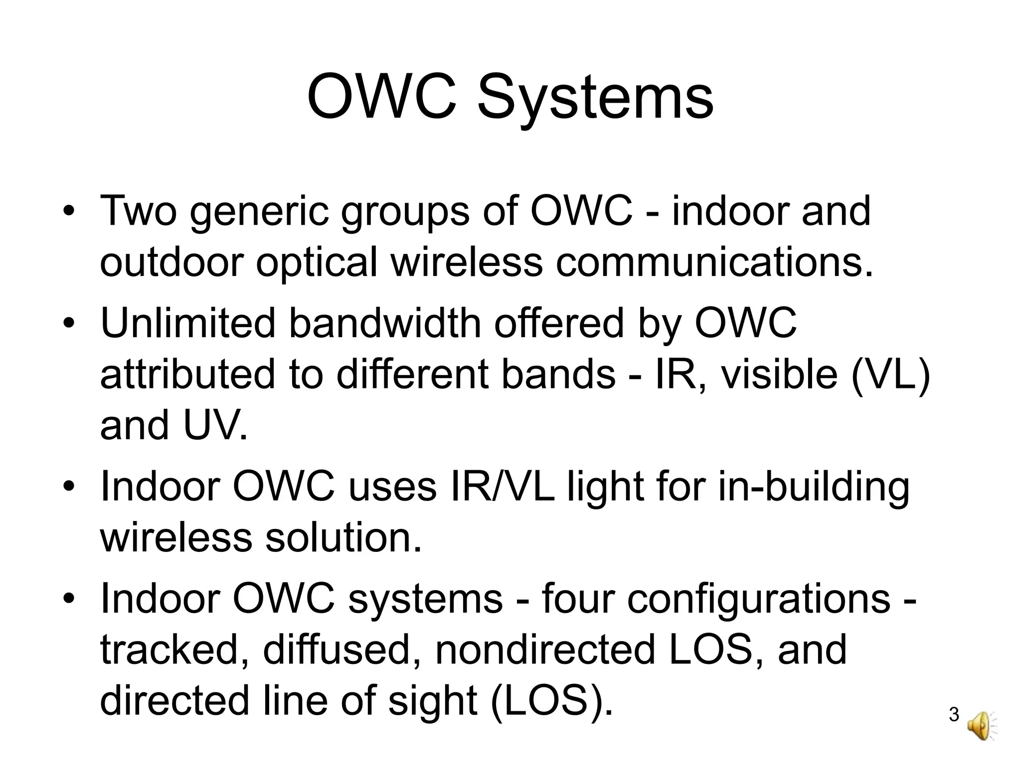
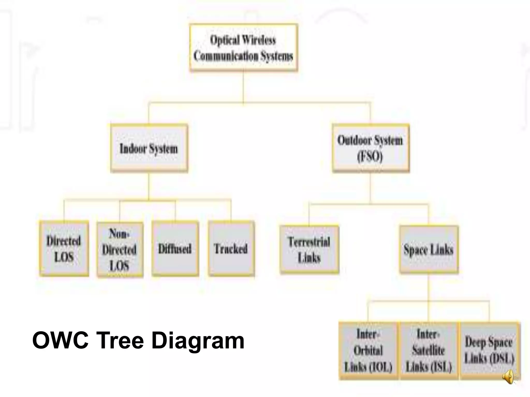
OWC Systems
• Twogeneric groups of OWC - indoor and
outdoor optical wireless communications.
• Unlimited bandwidth offered by OWC
attributed to different bands - IR, visible (VL)
and UV.
• Indoor OWC uses IR/VL light for in-building
wireless solution.
• Indoor OWC systems - four configurations -
tracked, diffused, nondirected LOS, and
directed line of sight (LOS).
5
OWC Systems
• OutdoorOWC employs optical carrier to
transport information from one point to
another over an unguided channel.
• OWC technology also known as a free-
space optical (FSO) communication
system.
• FSO operate at near IR frequencies,
classified into terrestrial and space optical
links.
11
OWC System
• Wavelengthranges of 780–850 nm and
1520–1600 nm commonly used in current
OWC equipments.
• Wavelength ranges located in atmospheric
transmission windows where molecular
absorption is negligible.
• Wavelength windows located in the region
of four specific wavelengths - 850, 1060,
1250 and 1550 nm experience attenuation
of less than 0.2 dB/km.
12.
12
OWC System
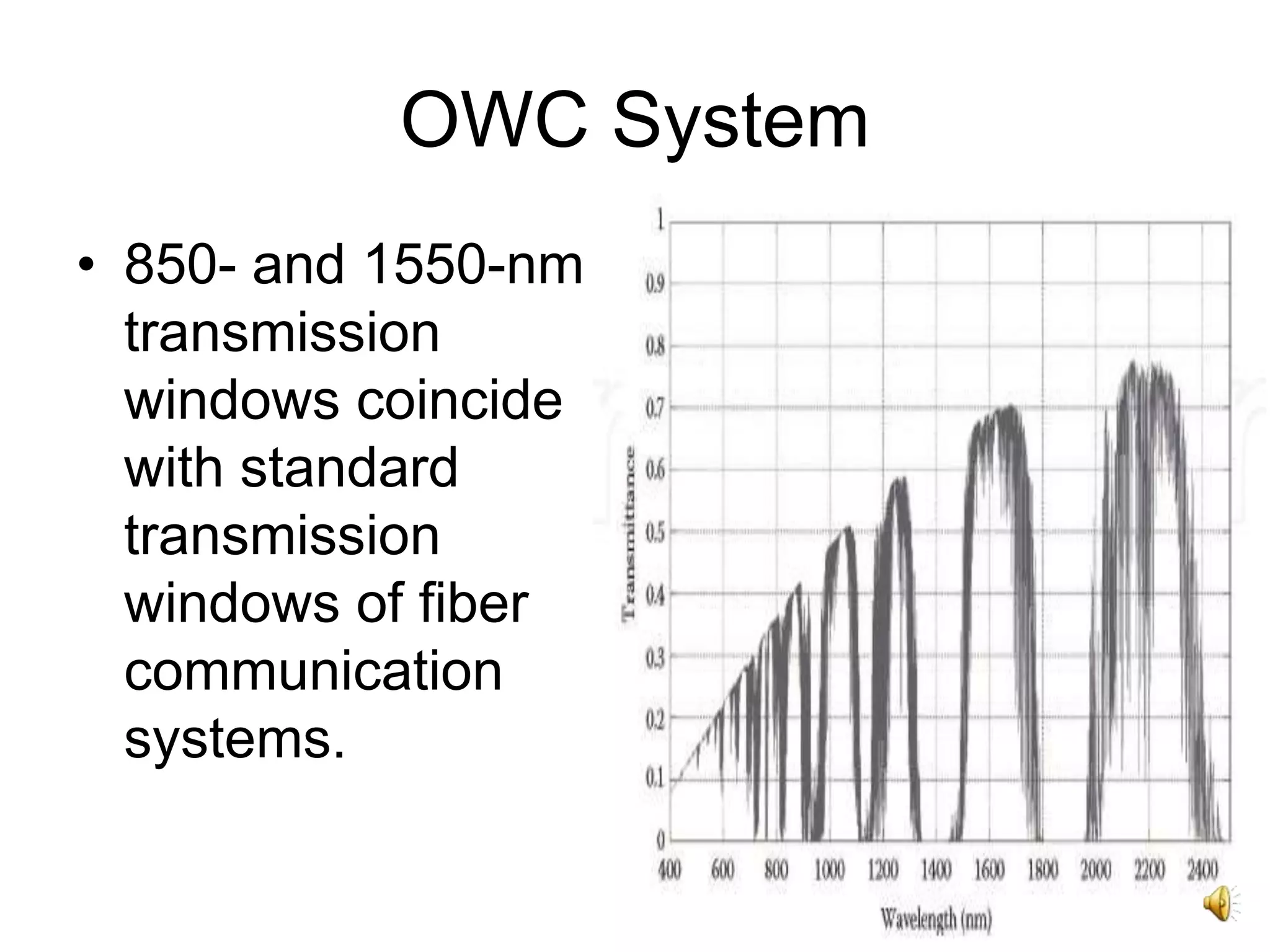
• 850-and 1550-nm
transmission
windows coincide
with standard
transmission
windows of fiber
communication
systems.
13.
13
OWC System
• 1520–1600-nmwavelengths compatible
with EDFA technology, helps achieve high
power and high-data rate systems.
• 1520–1600-nm wavelengths enable
transmission of about 50–65 times more
average output power than can be
transmitted at 780–850 nm.
14.
14
VLC System
• Addresseschallenges such as energy
efficiency, bandwidth limitation,
electromagnetic radiation, and safety in
wireless communications.
• Operates in the wavelength range of ~390–
750 nm.
• Current enhancement of LED chip design
with swift nanosecond-switching times and
extensive deployment of LEDs for energy
efficiency paves way for visible light
communication (VLC) system.
15.
15
VLC System
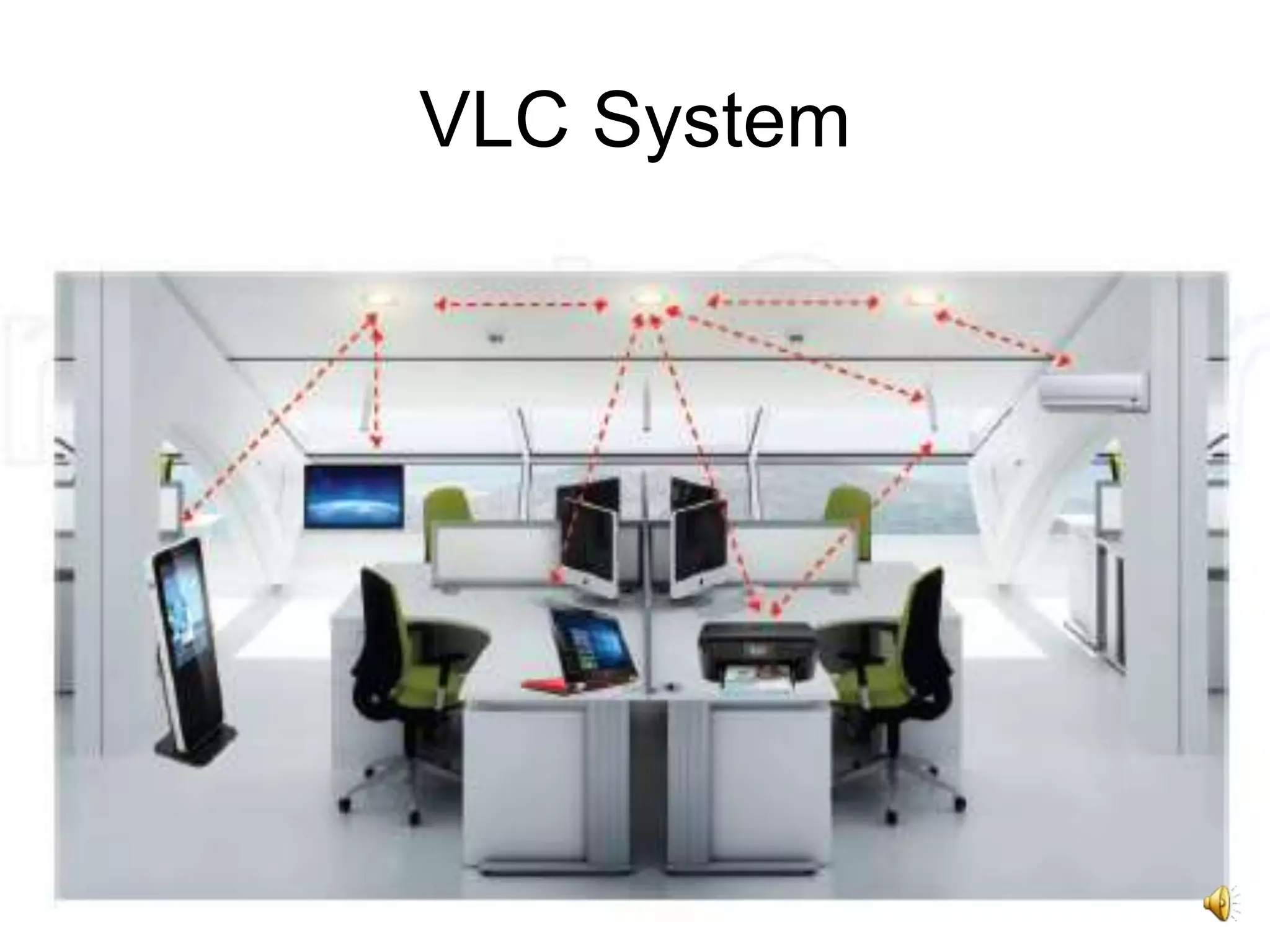
• Li-Fialternative in sensitive or hazardous
environments like airplanes, hospitals, and
industrial gas production plants where the
employment of RF technology is not
permitted.
• VLC based indoor navigation services offer
very high accuracy to within a few cm.
• No harmful radiations, no public health
concern.
17
VLC Transmitter
• LEDsand Lasers used as sources for
VLC.
• Use of white light based on LEDs and
wavelength converters.
• LED used when both communication and
illumination have to be performed using a
single device.
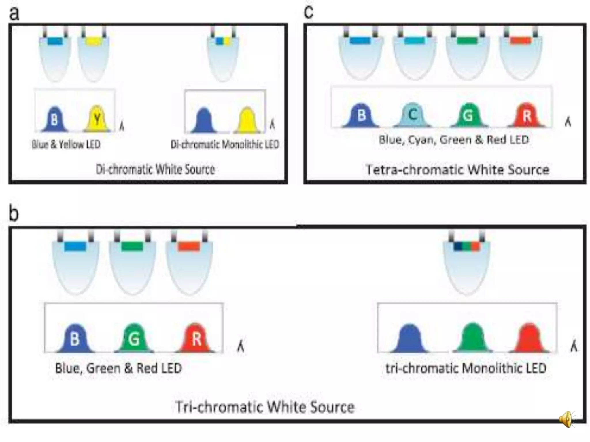
• Tetra-chromatic, dichromatic and tri-
chromatic modes for white light.
20
VLC Transmitter
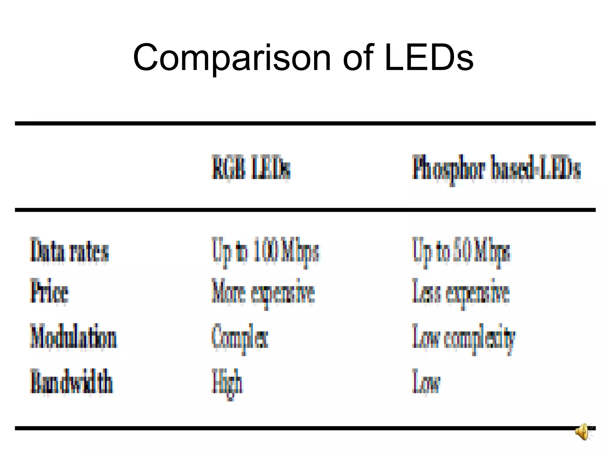
• RGBLED for white light generation - high
bandwidth and high data rates.
• RGB LED has high associated complexity
and modulation difficulties.
• Choice of LED based on the channel
model.
21.
21
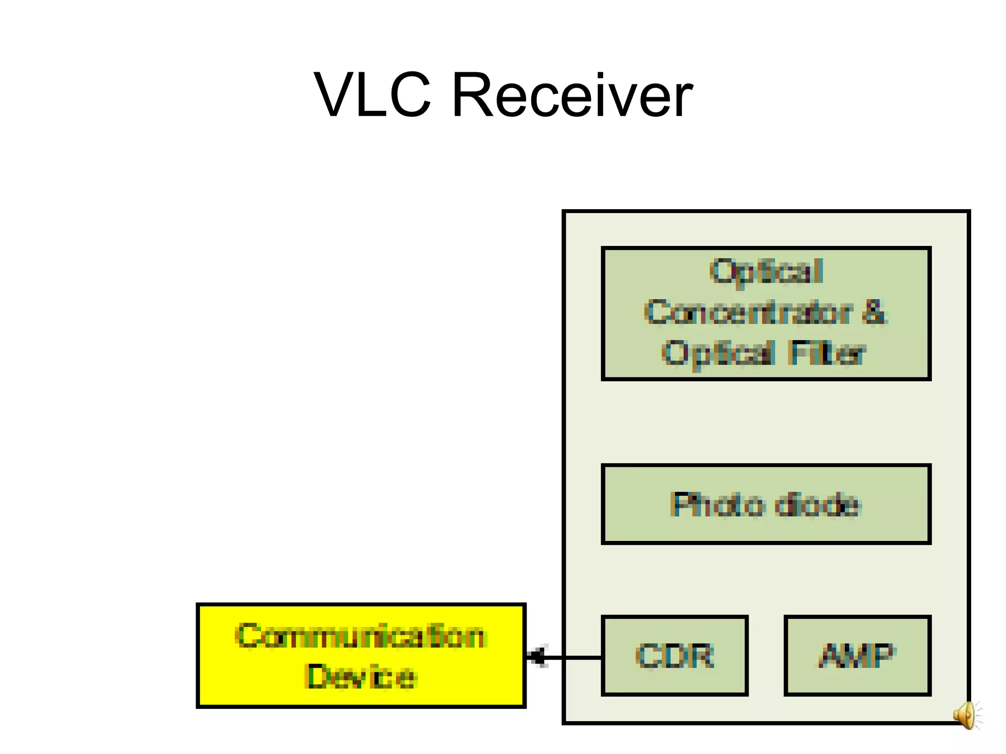
VLC Receiver
• Amplificationcircuit, optical filter and optical
concentrators.
• Beam divergence due to illuminating large
areas results in attenuation.
• Optical concentrator to compensate for
attenuation.
• Light detected using a photodiode in a
stationary receiver - silicon photodiode, PIN
diode or avalanche photodiode used.
• Converted to photo current.
22.
22
VLC Receiver
• Imagingsensors employed instead of
photodiodes in the case of mobility.
• Operating imaging sensors energy
expensive and slow, hence a trade-off
between cost, speed and complexity.
• Vulnerable to interference from other
sources such as sunlight and other
illumination.
• Optical filters to mitigate DC noise
components.
25
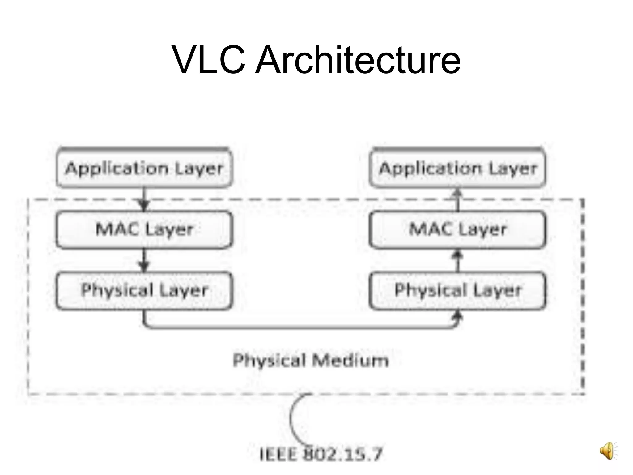
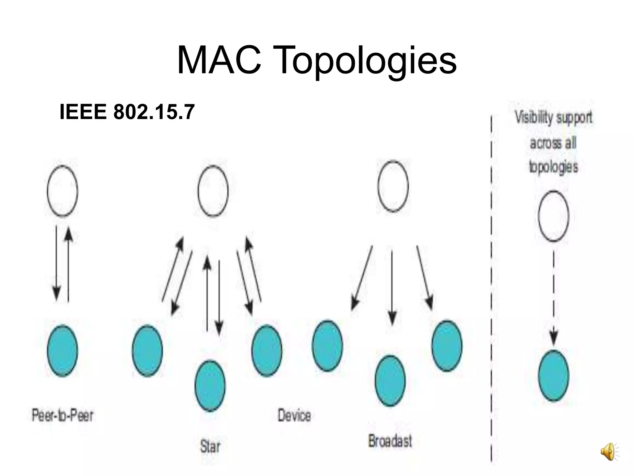
VLC Architecture
• Twointegral parts of a VLC system -
transmitter and receiver.
• Layered architecture of three common
layers - Physical Layer, MAC Layer and
Application Layer.
• IEEE 802.15.7 defines only two layers
(PHY and MAC) for simplicity.
27
MAC Layer Tasks
•Mobility support.
• Dimming support.
• Visibility support.
• Security support.
• Schemes for mitigation of flickering.
• Color function support.
• Network beacons generation if the device is a
coordinator.
• VPAN disassociation and association support.
• Providing a reliable link between peer MAC
entities.
29
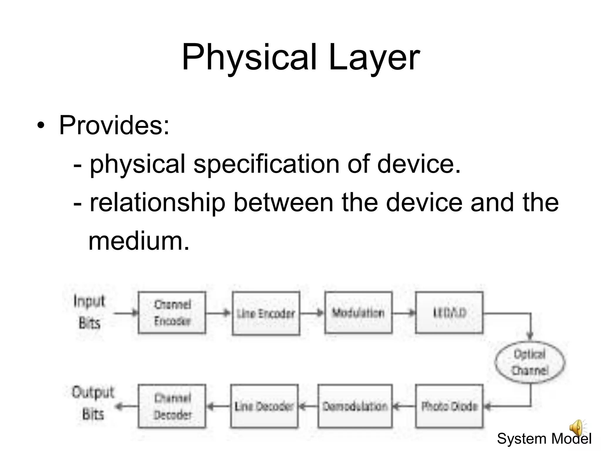
Physical Layer
• Provides:
-physical specification of device.
- relationship between the device and the
medium.
System Model
30.
30
Physical Layer
• Inputbit stream passed through the
channel encoder.
• Linear block codes, convolutional codes
and turbo codes used to enhance VLC
system performance.
• Channel encoded bit stream passed
through line encoder to yield encoded bit
stream.
31.
31
Physical Layer
• Modulation(ON–OFF keying, PPM and
PWM, etc.) performed.
• Finally, data drives LED for transmission
through the optical channel.
• Wavelength Division Multiplexing (WDM)
and Subcarrier Multiplexing (SCM) for bi-
directional transmission.
• Orthogonal Frequency Division Multiplexing
(OFDM) and Quadrature Amplitude
Modulation (QAM) to increase data rate.
32.
32
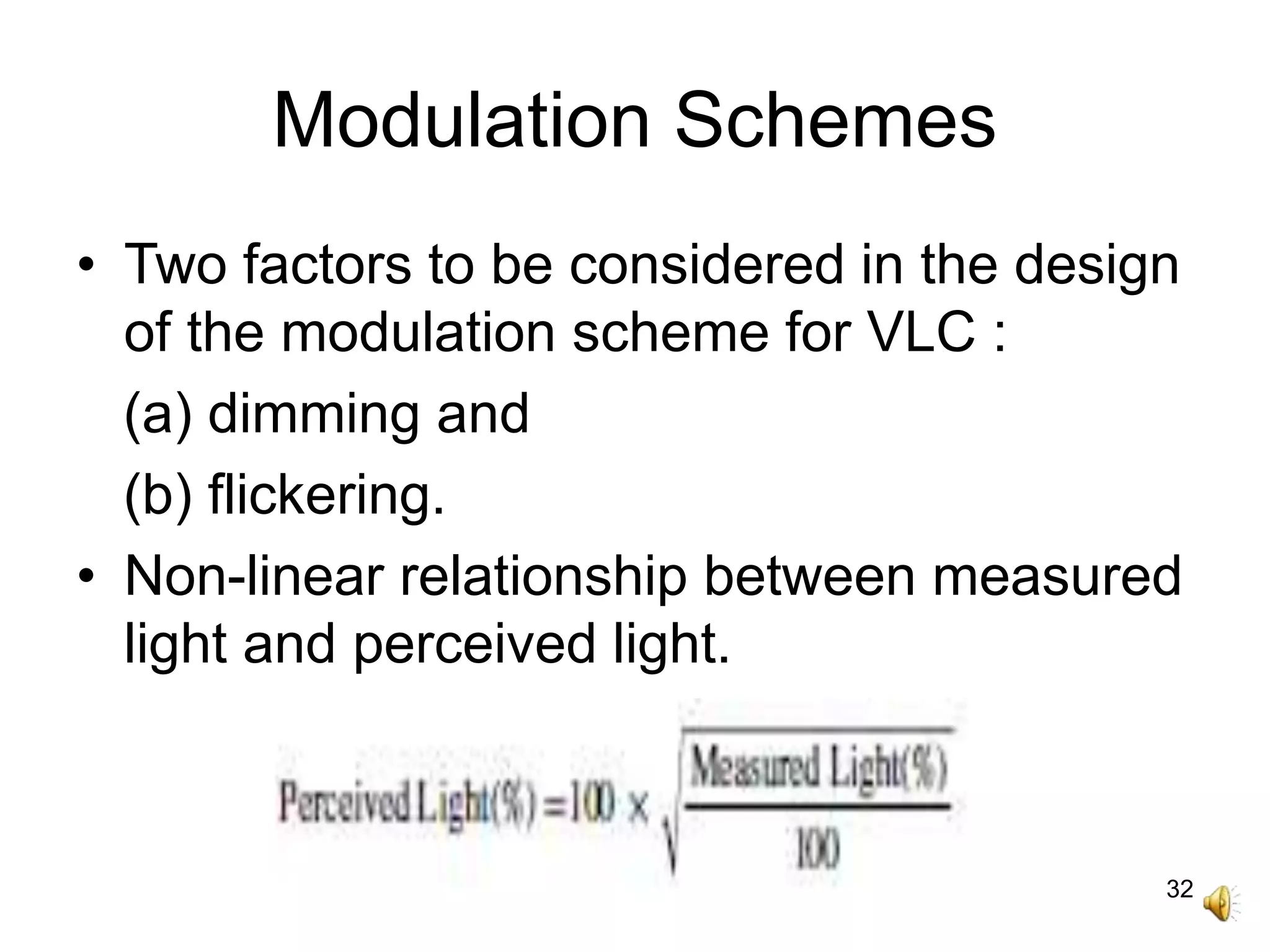
Modulation Schemes
• Twofactors to be considered in the design
of the modulation scheme for VLC :
(a) dimming and
(b) flickering.
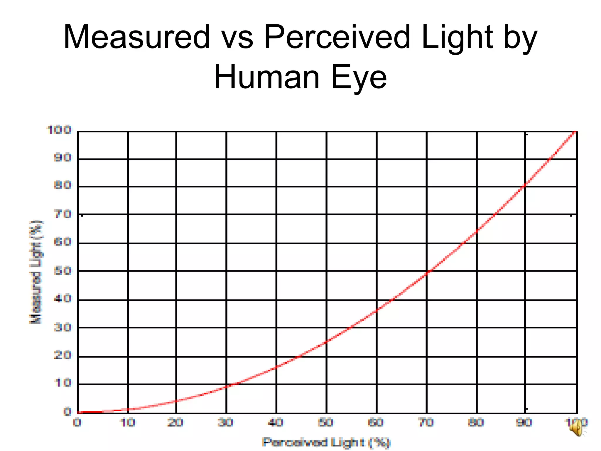
• Non-linear relationship between measured
light and perceived light.
34
Modulation Schemes
• Changesin brightness of modulated light
should not result in human-perceivable
fluctuations.
• IEEE 802.15.7 - switching to be done at a
rate faster than 200 Hz to avoid harmful
effects.
36
On-Off Keying
• LEDsturned off and on according to bits in
the stream
• LED not turned completely off in the off
state, but reduction in intensity level.
• Easy implementation.
• Done using white LEDs (a combination of
blue emitter and yellow phosphor).
• Low bandwidth due to slow time response
of the yellow phosphor.
37.
37
On-Off Keying
• Datarate of upto 10Mbps using NRZ OOK
with a white LED.
• Combination of analogue equalization with
blue filtering done to increase data rates
up to 125 Mbps and 100 Mbps.
• Limitation of OOK low data rates
motivated researchers to develop new
modulation techniques.
38.
38
Pulse Modulation Techniques
•PWM – pulse width varied according to
dimming levels.
• Using high PWM frequency, different
dimming levels achieved between 0% and
100%.
• Limitation of PWM - low data rate upto 4.8
Kbps.
• PWM combined with Discrete Multitone
(DMT) for joint communication & dimming
control with higher data rates.
39.
39
Pulse Modulation Techniques
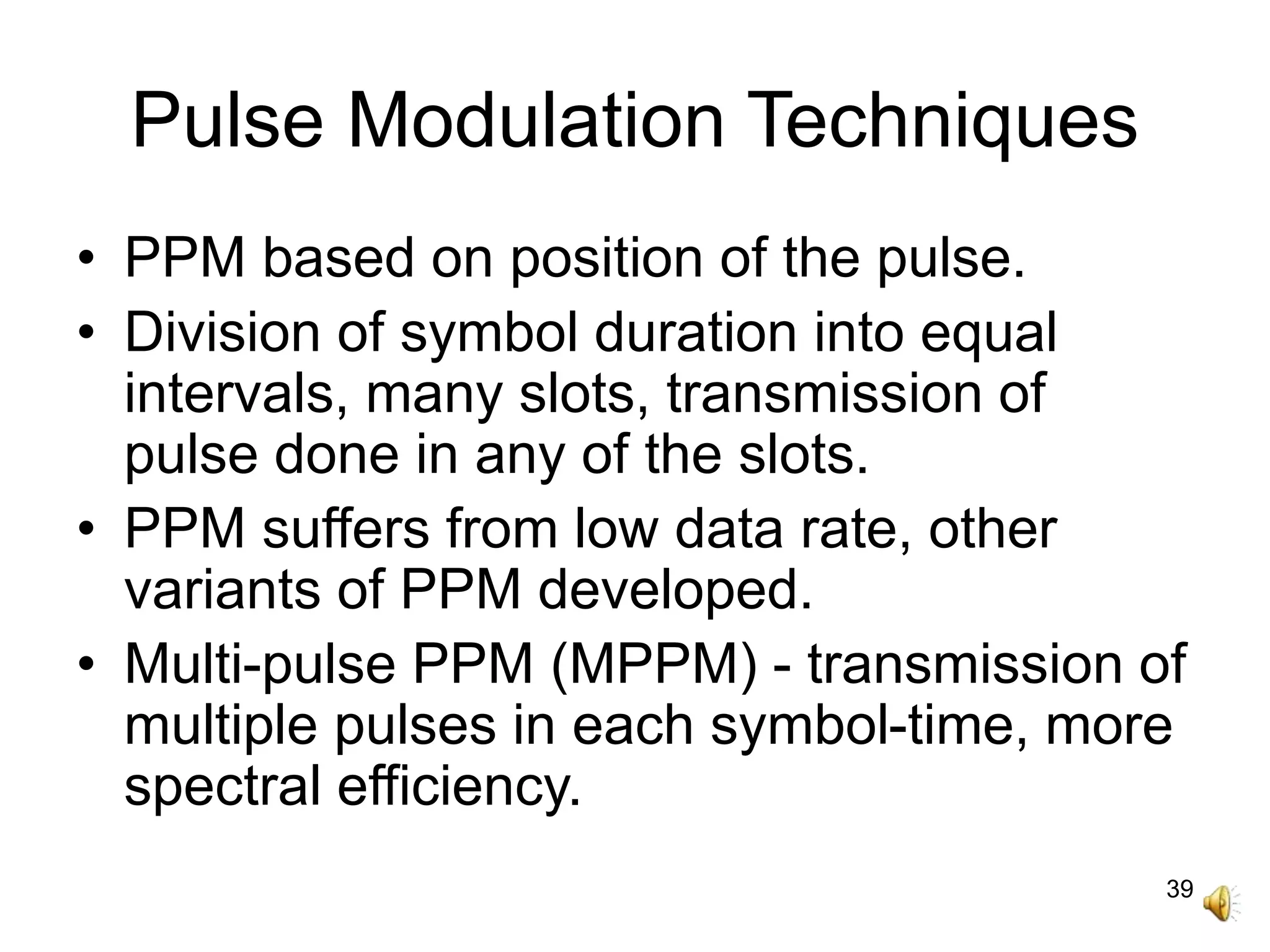
•PPM based on position of the pulse.
• Division of symbol duration into equal
intervals, many slots, transmission of
pulse done in any of the slots.
• PPM suffers from low data rate, other
variants of PPM developed.
• Multi-pulse PPM (MPPM) - transmission of
multiple pulses in each symbol-time, more
spectral efficiency.
40.
40
Pulse Modulation Techniques
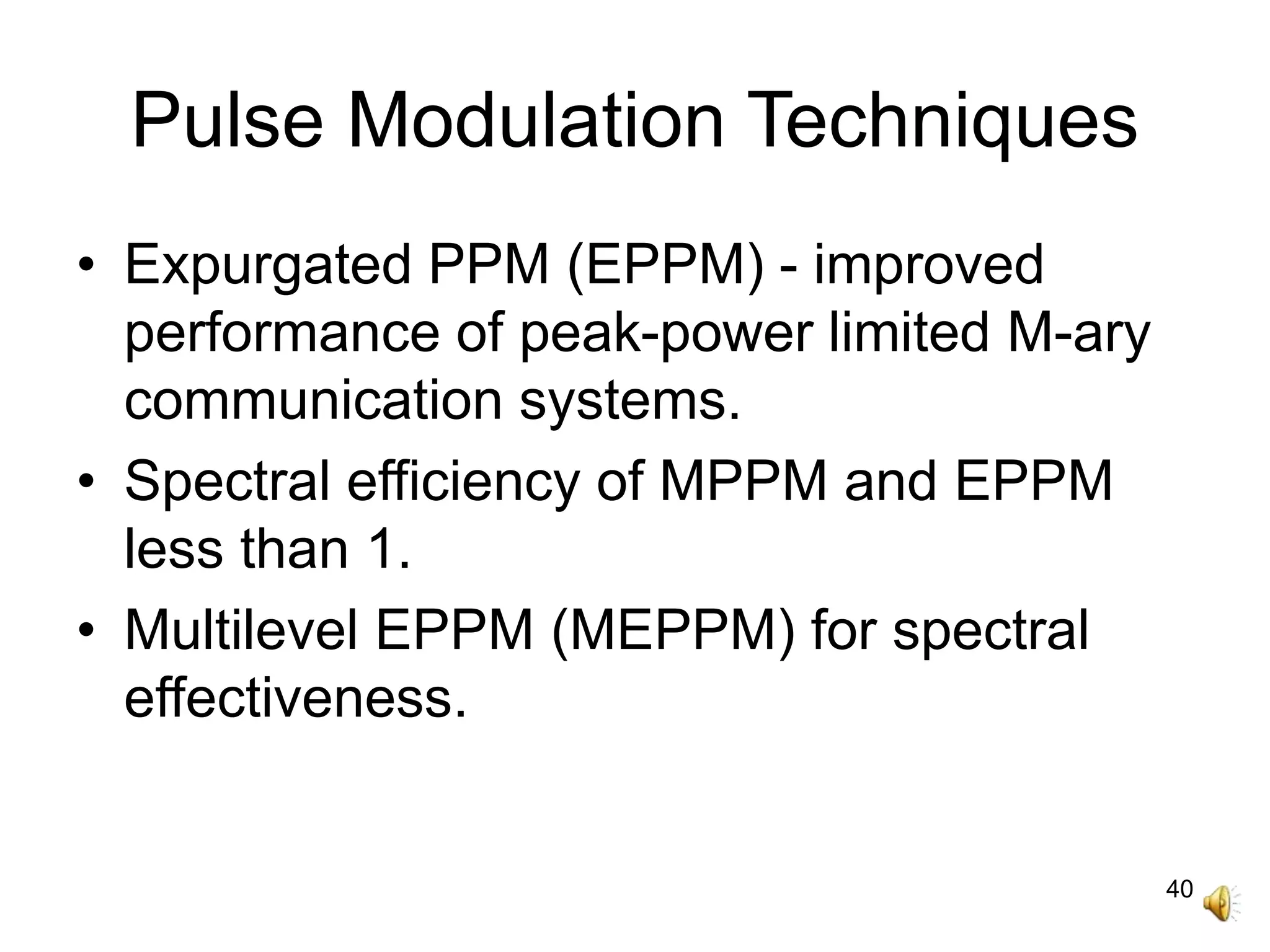
•Expurgated PPM (EPPM) - improved
performance of peak-power limited M-ary
communication systems.
• Spectral efficiency of MPPM and EPPM
less than 1.
• Multilevel EPPM (MEPPM) for spectral
effectiveness.
42
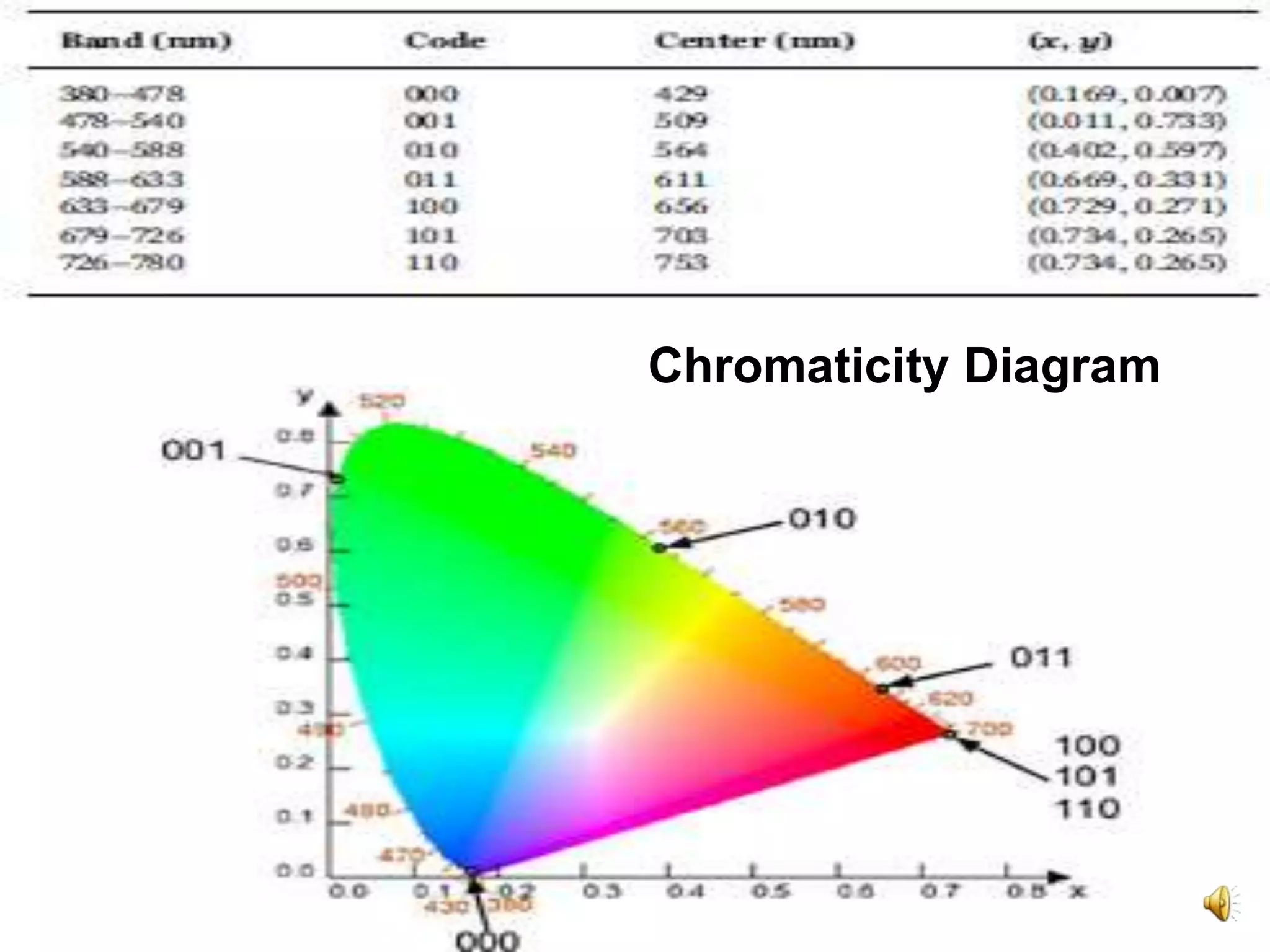
Color Shift Keying
(CSK)
•Enhanced data rates.
• Utilizes three separate LEDS - Green, Blue
and Red to produce White Light.
• Modulation using intensity of three colors in
an RGB LED source.
• CSK depends on the color space chromaticity
diagram.
• Maps all colors perceivable by eye into two
chromaticity parameters x and y.
44
VLC Advantages
Huge Bandwidth:
-unlimited and unlicensed bandwidth.
- 380 nm to 780 nm.
- VLC 350 THz support multi-gigabit-per-
second data rates with LED arrays in a
multiple-input multiple-output (MIMO)
configuration.
- alternative to indoor IR that operates at
780–950 nm.
45.
45
VLC Advantages
Low PowerConsumption:
- provides both communication and
lighting, at Gbps data rates.
- consume low power compared to
costly RF alternatives.
Low Bandwidth:
- inexpensive components, compact, light
weight, amenable to dense integration,
very long lifespan.
46.
46
VLC Advantages
- largeunlicensed optical spectrum.
- lower power-per-bit cost compared to
RF communications.
- cheaper.
No health concerns:
- no generate radiation that leads to
public health concern.
47.
47
VLC Advantages
- lowerscarbon dioxide emission.
- little extra power consumption for
communication.
Ubiquitous Computing:
- wide range of network connectivity.
- may incorporate luminous devices like
traffic signs, commercial displays,
indoor/outdoor lamps, TVs, car head
lights/tail lights.
48.
48
VLC Advantages
Inherentsecurity:
- high security.
- highly intricate for a network intruder
outside to pick up the signal.
- alternative technology in sensitive or
hazardous environments.
Indoor localization:
- existing RF-based global positioning
system (GPS) gives inadequate/no
network coverage.
49.
49
VLC Advantages
- highattenuation, multipath, and safety
regulation, accuracy of only up to
a few meters for the RF-based GPS.
- VLC-based indoor positioning to attend to
issues in enclosed environments.
- high accuracy to within a few cm.
- indoor localization system using the white
LEDs.
50.
50
VLC Advantages
- LEDsgive better light source more than
400 lux.
- LEDs have longer lifespan, ecological
and financial benefits.
- high-speed data transmission.
- simultaneous employment of light
sources for data communication as well
as illumination.
51.
51
Challenges
• Flicker mitigation:
-Flicker:
variation in the brightness of light perceived
by human naked eye.
result of continuous switching on and
off of the light source during data
transmission.
can instigate negative/harmful physiological
changes in humans.
52.
52
Challenges
• Flicker preventedby making changes in
brightness to be within the maximum
flickering time period (MFTP).
• MFTP - maximum time period within which
the light intensity can be changed without
any perception by the human eye.
• Modulation formats for flicker mitigation.
• IEEE 802.15.7 standard proposes variable
pulse position modulation (VPPM) for VLC
system.
53.
53
Challenges
• Dimming support:
•Variable pulse position modulation (VPPM)
for VLC system for ability to control
dimming.
• VPPM integrates PPM and PWM to
support communication with dimming
control.
54.
54
Challenges
• High pathlosses.
• Multipath induced intersymbol interference
(ISI).
• Artificial light-induced interference.
• Blocking.
• LED electro-optic response nonlinearity.
• Interference between VLC devices.
• Integration with existing technologies.
55.
55
VLC Standardisation
• Standardisationto tackle challenges.
• Performed by Visible Light Communication
Consortium (VLCC), Japan and IEEE.
• Japan Electronics & Information
Technology Industries Association (JEITA)
CP-1221, JEITA CP-1222 and JEITA CP-
1223 published by VLCC.
• IEEE 802.15.7 standard for physical and
MAC layers - minimum benchmark for
development of new products.
56.
56
Why Standardisation
• Providingaccess to several hundred THz
bands.
• Providing immunity against EMI.
• Communication that complements extra
services to the existing visible light
infrastructure.
• Specifying FEC schemes, modulation
techniques and data rates for VLC
communication.
57.
57
Why Standardisation
• Channelaccess mechanisms such as
Contention Access Period (CAP),
Contention-Free Period (CFP) and
visibility support when channel access
described.
• PHY layer specifications, such as optical
mapping, Tx-Rx turn around time, Rx-Tx
turn around time and flicker and dimming
mitigation explained.

![6
OWC Systems
• FSO consists of:
- building-to-building.
- satellite-to-ground.
- ground-to-satellite.
- satellite-to-satellite.
- satellite-to-airborne platforms
(unmanned aerial vehicles [UAVs] or
balloons).](https://image.slidesharecdn.com/visiblelightcommunicationvlcsystems-201226063250/75/Visible-light-communication-vlc-systems-6-2048.jpg)