Downloaded 271 times
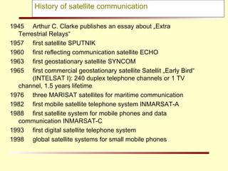
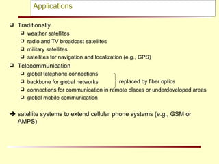
![Satellite period and orbits 10 20 30 40 x10 6 m 24 20 16 12 8 4 radius satellite period [h] velocity [ x1000 km/h] synchronous distance 35,786 km](https://image.slidesharecdn.com/mahe5-090520082123-phpapp01/85/MSAT-6-320.jpg)

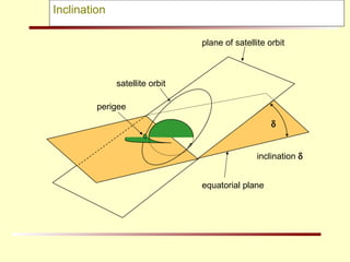
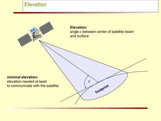
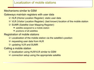
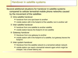
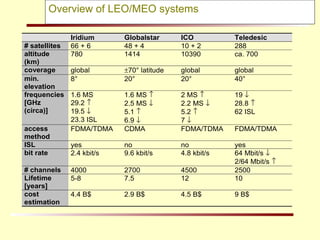

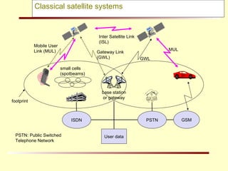
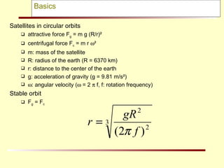
This document discusses the history and basics of satellite communication systems. It covers: - The first satellites launched in the 1940s-1990s and the development of satellite phone systems. - The types of satellite orbits including LEO, MEO, and GEO and how factors like altitude and inclination determine satellite period and coverage areas. - How satellite systems extend cellular networks to provide global mobile communication through techniques like inter-satellite links and handovers between satellites and gateways. - The challenges of satellite systems including higher latency compared to terrestrial networks and the need for complex routing and localization as satellites move.