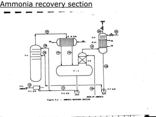
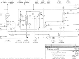
BASICS OF UREA
PROCESS
Presented by:-
K. K. Dubey
Manager (Prod)
Urea plants at NFL Vijaipur
• Four streams of Urea
• 1515 MTPD each in line 1 & 1615 MTPD each
in line 2.
• Line –I Urea plants commissioned in 1987
• Line-II Urea plants commissioned in 1997
• Snamprogetti (Italy)technology
Unique features introduced By Snam
• The installation of ejectors
• Use of centrifugal compressors
• Bimetallic tubes
• Design of horizontal layout
Snamprogetti process at Vijaipur
Snamprogetti Urea
PROCESS DESCRIPTION-MAIN PROCESS STEPS
• CO2 COMPRESSION
• HIGH PRESSURE SYNTHESIS LOOP
• MEDIUM PRESSURE RECOVERY SECTION
• LOW PRESSURE SECTION
• VACUUM EVAPORATION SECTION
Description of the process
• The urea production process takes place through the
following main operations-
 1. Urea synthesis and high pressure recovery
 2. Urea purifications and low pressure recovery
 3.Urea concentration
 4.Urea prilling
Snamprogetti Urea
HIGH PRESSURE SYNTHESIS LOOP
• CO2 COMPRESSION
• REACTION OF NH3 AND CO2
• UREA FORMATION
• NH3/CO2 AND H2O/CO2 MOLAR RATIO
• DECOMPOSITION OF CARBAMATE
• LOW PRESSURE STEAM PRODUCTION
Urea synthesis & High pressure recovery
• Urea is produced by synthesis from liquid ammonia
and gaseous carbondioxide.
• In the reactor 11/21 R-1,the ammonia and
Carbondioxide react to form Ammonium
Carbamate,a portion of which dehydrates to form
Urea and water.
• The reactions are as follows:
 2NH3 + CO2 = NH2COONH4
 NH2COONH4 = NH2COONH2 + H2O
Urea synthesis & High pressure recovery
• In synthesis conditions (T=188°C & P=155
kg/cm2),the first reaction occurs rapidly and is
completed,the second reaction occurs slowly
and determines the reactor volume.
• The fraction of Ammonium carbamate that
dehydrates is determined by the ratio of the
various reactants,the operating temperature
and residence time in the reactor.
Urea synthesis & High pressure recovery
• The mole ratio of NH3 to CO2 is 3.3~3.6.
• The mole ratio of H2O to CO2 is 0.5 to 0.7.
• The total flow of liquid Ammonia coming directly
from the battery limits is measured by turbine flow
meter FQR-106 and then diverted to 11/21 unit.The
flow of liquid ammonia going to each unit is
measured by FIR 104 and temperature by TI-1-113
(12°C), is collected in the Ammonia receiver tank
11/21 V-1.
MP section
Urea synthesis & High pressure recovery
• From V-1,it is drawn and compressed at about
22.4 kg/cm2 pressure by means of centrifugal
pump P-5 A/B.
• Part of this ammonia is sent to the Medium
pressure absorber 11/21 C-1,the remaining
part enters the high pressure synthesis loop.
MP section
Urea synthesis & High pressure recovery
• The ammonia feeding the synthesis loop is
compressed by two low –speed,heavy duty
reciprocating pumps 11/21 P-1 A/B at a pressure of
about 220 ata.
• Before entering the reactor the Ammonia feed is
used as motive fluid in the Carbamate Ejector 11/21
EJ-1,where the carbamate coming from the
Carbamate Separator 11/21 MV-1 is compressed
upto the synthesis pressure.
HP section
Urea synthesis & High pressure recovery
• The liquid mixture of NH3 and Carbamate enters the
reactor where NH3 reacts with the compressed
carbondioxide.
• The CO2 drawn at Urea plant battery limits at about
1.5 ata and about 40°C enters the centrifugal
compressor 11/21 K-1 and leaves at a pressure of
about 160ata.
• The CO2 at a pressure 160 ata and temp. 130°C is fed
to Urea reactor (11/21 R-1) through K-1 Discharge
Separator (11/21 MV-8)
HP section
Urea synthesis & High pressure recovery
• A small quantity of air is added to the Carbondioxide
at the compressor suction in order to passivate the
stainless steel surfaces,thus protecting them for
corrosion due to both reagent and reaction product.
• The reaction products,leaving the reactor,flow to the
steam heated falling film type stripper 11/21 E-
1,which operates at 146 kg/cm2g pressure.The
mixture is heated up as it flows down the
stripper.The CO2 content is reduced by the stripping
action of the Ammonia as it boils out of the solution.
K1
Urea synthesis & High pressure recovery
• For the bottom of bimetallic stripper,passivation air is
required in continuous way.For this passivation air
compressor K-3A/B are installed.
• The carbamate decomposition heat is supplied by 24
ata saturated steam.The overhead gases and the
recovered solution from M.P.absorber (C-1),all flow
to the high pressure Carbamate condensers (E-5)
where the total mixture ,except for a few inerts,is
condensed and recycled to the Reactor by means of
ejector (EJ-1).
HP section
Urea synthesis & High pressure recovery
• The condensation of gases at high pressure and
temperature permits the production of 4.5 ata steam
in the high pressure Carbamate condenser.
• In the Carbamate Separator (MV-1) the
uncondensable gases,consisting of inert gases
containing a little quantity of NH3 and CO2
unreacted in the condenser,are separated from the
carbamate solution and sent to the Medium pressure
decomposer (E-2).
HP section
LS
TO E-2
R-1
PV-7A/B
TO M.P. SECTION
TO B/D
M.S
CO2
FROM P-2
E-1
MV-4
H.P.
SECTION
E-5
MV-1
AMMONIA
T-1720C
T-190
P-158Ata
T-2050C
T-1900C
NO. OF TRAYS 15
20
22
23
Urea purification and low pressure recovery
• Urea purification takes place in two stages at
decreasing pressures as follows:
Ist stage at 18 ata pressure
2nd stage at 4.5 ata pressure
Snamprogetti Urea
MEDIUM PRESSURE RECOVERY SECTION
• CARBAMATE DECOMPOSITION
• CO2 ABSORPTION
• NH3 RECOVERY
• NH3 PUMPING TO 225 ATA
• CARBAMATE PUMPING TO 160 ATA
• NH3 MAKE UP FROM B.L.
1st purification and recovery stage at
18 ata
• The solution with a low residual CO2 content,leaving the
bottom of the stripper is expanded at the pressure of 18 ata
and enters the Medium pressure Decomposer E-2 (falling
film type).
• This equipment is divided into two parts:
 Top separator MV-2 where the residual gases are removed
flash gases are removed before the solution enters the tube
bundle.
 Decomposition section where the residual carbamate is
decomposed and the required heat is supplied by 24 ata
steam condensate flowing out of the stripper.
MP section
1st purification and recovery stage at
18 ata
• The NH3 and CO2 rich gases leaving the top separator are
sent to the medium pressure condenser (E-7) where they are
partially absorbed in aqueous carbamate solution coming
from the low pressure recovery section via pump (P-3).
• A tempered water circuit is provided to prevent carbamate
solidification and to keep a suitable cooling water
temperature at the medium pressure condenser inlet
recirculating the cooling water by means of pump (P-4 A/B)
• In the condenser,CO2 is almost totally absorbed.
Mp section
1st purification and recovery stage at
18 ata
• The mixture from E-7 flows to the medium pressure
absorber (C-1) where the gaseous phase coming
from the solution enters the rectification section.
• This is of bubble cap trays type and performs CO2
absorption and NH3 rectification.
• The trays are fed by pure reflux ammonia which
eliminates residual CO2 and H2O contained in the
inert gases.
MP
1st purification and recovery stage at
18 ata
• Reflux ammonia is drawn from the Ammonia
receiver (V-1) and sent to the column C-1 by means
of centrifugal pump (P-5 A/B).
• A current of inert gases saturated with NH3 with
some ppm of CO2 residue comes out from the top
of the rectification section.The bottom solution is
recycled by pump (P-2 A/B) to the synthesis
recovery section.
MP
1st purification and recovery stage at
18 ata
• NH3 with inert gases leaving the C-1 top is partially
condensed in the Ammonia condenser E-9
A/B.From here the liquid and gaseous NH3 phases
are sent to the Ammonia receiver V-1.
• The inert gases,saturated with Ammonia,leaving
the receiver,enter the Ammonia recovery tower (C-
5) where additional amount of ammonia is
condensed by the cold ammonia from the Urea
plant battery limits.
• The condensed ammonia is recovered in V-1
1st purification and recovery stage at
18 ata
• The inert gases,containing residue ammonia,are
sent to the medium pressure falling film absorber
(E-11),where they meet a countercurrent water
flow which absorbs gaseous ammonia.
• The absorption heat is removed by cooling
water.From the bottom of E-11 the water ammonia
solution is recycled back to the medium pressure
absorber C-1 by means of pump P-7 A/B
1st purification and recovery stage at
18 ata
• The upper part of the medium pressure
absorber consists of 3 valve trays (C-3) where
the inert gases are submitted to a final
washing by means of the same absorption
water.
• In this way the inerts are collected to
blowdown practically free from ammonia.
Medium and low
pressure decomposition
11
Ammonia recovery section
17
18
32
33
34
Snamprogetti Urea
LOW PRESSURE SECTION
• RESIDUAL CARBAMATE DECOMPOSITION
• CARBAMATE RECOVERY
• WWT SECTION GAS RECOVERY
2nd purification and recovery stage at
4.5 ata
• The solution leaving the bottom of medium pressure
decomposer is expanded at 4.5 ata pressure and enters the
low pressure decomposer E-3.
• This is divided into two parts:
 Top separator (MV-3) where the released flash gases are
removed before the solution enters the tube bundle.
 Decomposition section where the last residual carbamate is
decomposed and the required heat is supplied by means of
4.5 ata saturated steam.
LP
2nd purification and recovery stage at
4.5 ata
• The gases leaving the top separator are sent to the Low
pressure condenser (E-8) where they are absorbed in an
aqueous carbonate solution coming from the waste water
treatment section.
• The absorption and condensation heat is removed by cooling
water.
• From the condenser bottom,the liquid phase,with the
remaining inert gases,is sent to the carbonate solution tank
(V-3).From here the carbonate solution is recycled back to
the medium pressure condenser E-7 by means of pump P-3
A/B.
2nd purification and recovery stage at
4.5 ata
• The inert gases which essentially contain Ammonia
vapour,flow directly into the low pressure falling
film absorber (E-12),where ammonia is absorbed by
a countercurrent water flow.
• The absorption heat is removed by cooling
water.The inert gases,washed in the low pressure
inert washing tower C-4 are collected to Blow down
practically free from ammonia.
Snamprogetti Urea
VACUUM EVAPORATION SECTION
• UREA CONCENTRATION IN TWO STAGES (0.3
AND 0.03 ATA)
• UREA SOLUTION STORAGE & RECOVERY
Urea concentration section
• As it is necessary in order to prill urea,to
concentrate the urea solution upto 99.7% a
vacuum concentration section in two stages is
provided.
• The solution leaving the low pressure
decomposer bottom with about 71% urea is
sent to the first vacuum concentrator E-14
operating at a pressure of 0.3 ata.
Urea concentration section
• The mixed phase coming out of E14 enters the
gas liquid separator MV-6 from where vapours
are extracted by the first vacuum system ME-4
while the solution enters the second vacuum
concentrator E-15 operating at a pressure of
0.03 ata.
• The two concentrations are fed by saturated
steam at 4.5 ata.
Urea concentration section
• The mixed phase coming out of E-15 enters
the gas liquid separator MV-7 from where
vapours are extracted by the second vacuum
system ME-5.
Urea Prilling
• The melted urea leaving the second vacuum
separator is sent to the prilling bucket ME-
8A/B by means of pump P-8 A/B.
• The urea coming out of the bucket in the form
of drops along the prilling tower ME-6 and
encounters a cold air flow which causes its
solidification.
Louvers
For
Recovery
To urea tank
V-5
Urea solution
Cyclone
Separator
Dust Recovery
Blower
ET-1
PRILLING
BUCKET
AIR
3-WAY
VALVE
NATURAL PRILLING
TOWER
P.T. LINE -1 LINE-2
DIA 28 M 26 M
PRILLING HEIGHT 72M 80
M
TOTAL HEIGHT 96 M 104M
Urea Prilling
• The solid prills falling to the bottom of the prilling
tower are sent into the belt conveyor MT-1 by the
rotary scrapper ME-10.From here they are sent
through lumps separator ME-11 to retain lumps only
and then to the product belt conveyor MT-3 which
carries the product to the Urea storage section.
• Urea lumps by means of Urea recycle belt conveyor
ET-2 are recycled back to the underground Urea
lumps dissolving tank V-4 where they are dissolved.
THANK YOU

urea process technology must read interusting.ppt

  • 1.
    BASICS OF UREA PROCESS Presentedby:- K. K. Dubey Manager (Prod)
  • 2.
    Urea plants atNFL Vijaipur • Four streams of Urea • 1515 MTPD each in line 1 & 1615 MTPD each in line 2. • Line –I Urea plants commissioned in 1987 • Line-II Urea plants commissioned in 1997 • Snamprogetti (Italy)technology
  • 3.
    Unique features introducedBy Snam • The installation of ejectors • Use of centrifugal compressors • Bimetallic tubes • Design of horizontal layout
  • 4.
  • 5.
    Snamprogetti Urea PROCESS DESCRIPTION-MAINPROCESS STEPS • CO2 COMPRESSION • HIGH PRESSURE SYNTHESIS LOOP • MEDIUM PRESSURE RECOVERY SECTION • LOW PRESSURE SECTION • VACUUM EVAPORATION SECTION
  • 6.
    Description of theprocess • The urea production process takes place through the following main operations-  1. Urea synthesis and high pressure recovery  2. Urea purifications and low pressure recovery  3.Urea concentration  4.Urea prilling
  • 7.
    Snamprogetti Urea HIGH PRESSURESYNTHESIS LOOP • CO2 COMPRESSION • REACTION OF NH3 AND CO2 • UREA FORMATION • NH3/CO2 AND H2O/CO2 MOLAR RATIO • DECOMPOSITION OF CARBAMATE • LOW PRESSURE STEAM PRODUCTION
  • 8.
    Urea synthesis &High pressure recovery • Urea is produced by synthesis from liquid ammonia and gaseous carbondioxide. • In the reactor 11/21 R-1,the ammonia and Carbondioxide react to form Ammonium Carbamate,a portion of which dehydrates to form Urea and water. • The reactions are as follows:  2NH3 + CO2 = NH2COONH4  NH2COONH4 = NH2COONH2 + H2O
  • 9.
    Urea synthesis &High pressure recovery • In synthesis conditions (T=188°C & P=155 kg/cm2),the first reaction occurs rapidly and is completed,the second reaction occurs slowly and determines the reactor volume. • The fraction of Ammonium carbamate that dehydrates is determined by the ratio of the various reactants,the operating temperature and residence time in the reactor.
  • 10.
    Urea synthesis &High pressure recovery • The mole ratio of NH3 to CO2 is 3.3~3.6. • The mole ratio of H2O to CO2 is 0.5 to 0.7. • The total flow of liquid Ammonia coming directly from the battery limits is measured by turbine flow meter FQR-106 and then diverted to 11/21 unit.The flow of liquid ammonia going to each unit is measured by FIR 104 and temperature by TI-1-113 (12°C), is collected in the Ammonia receiver tank 11/21 V-1. MP section
  • 11.
    Urea synthesis &High pressure recovery • From V-1,it is drawn and compressed at about 22.4 kg/cm2 pressure by means of centrifugal pump P-5 A/B. • Part of this ammonia is sent to the Medium pressure absorber 11/21 C-1,the remaining part enters the high pressure synthesis loop. MP section
  • 12.
    Urea synthesis &High pressure recovery • The ammonia feeding the synthesis loop is compressed by two low –speed,heavy duty reciprocating pumps 11/21 P-1 A/B at a pressure of about 220 ata. • Before entering the reactor the Ammonia feed is used as motive fluid in the Carbamate Ejector 11/21 EJ-1,where the carbamate coming from the Carbamate Separator 11/21 MV-1 is compressed upto the synthesis pressure. HP section
  • 13.
    Urea synthesis &High pressure recovery • The liquid mixture of NH3 and Carbamate enters the reactor where NH3 reacts with the compressed carbondioxide. • The CO2 drawn at Urea plant battery limits at about 1.5 ata and about 40°C enters the centrifugal compressor 11/21 K-1 and leaves at a pressure of about 160ata. • The CO2 at a pressure 160 ata and temp. 130°C is fed to Urea reactor (11/21 R-1) through K-1 Discharge Separator (11/21 MV-8) HP section
  • 14.
    Urea synthesis &High pressure recovery • A small quantity of air is added to the Carbondioxide at the compressor suction in order to passivate the stainless steel surfaces,thus protecting them for corrosion due to both reagent and reaction product. • The reaction products,leaving the reactor,flow to the steam heated falling film type stripper 11/21 E- 1,which operates at 146 kg/cm2g pressure.The mixture is heated up as it flows down the stripper.The CO2 content is reduced by the stripping action of the Ammonia as it boils out of the solution. K1
  • 15.
    Urea synthesis &High pressure recovery • For the bottom of bimetallic stripper,passivation air is required in continuous way.For this passivation air compressor K-3A/B are installed. • The carbamate decomposition heat is supplied by 24 ata saturated steam.The overhead gases and the recovered solution from M.P.absorber (C-1),all flow to the high pressure Carbamate condensers (E-5) where the total mixture ,except for a few inerts,is condensed and recycled to the Reactor by means of ejector (EJ-1). HP section
  • 16.
    Urea synthesis &High pressure recovery • The condensation of gases at high pressure and temperature permits the production of 4.5 ata steam in the high pressure Carbamate condenser. • In the Carbamate Separator (MV-1) the uncondensable gases,consisting of inert gases containing a little quantity of NH3 and CO2 unreacted in the condenser,are separated from the carbamate solution and sent to the Medium pressure decomposer (E-2). HP section
  • 17.
    LS TO E-2 R-1 PV-7A/B TO M.P.SECTION TO B/D M.S CO2 FROM P-2 E-1 MV-4 H.P. SECTION E-5 MV-1 AMMONIA T-1720C T-190 P-158Ata T-2050C T-1900C NO. OF TRAYS 15
  • 18.
  • 21.
    Urea purification andlow pressure recovery • Urea purification takes place in two stages at decreasing pressures as follows: Ist stage at 18 ata pressure 2nd stage at 4.5 ata pressure
  • 22.
    Snamprogetti Urea MEDIUM PRESSURERECOVERY SECTION • CARBAMATE DECOMPOSITION • CO2 ABSORPTION • NH3 RECOVERY • NH3 PUMPING TO 225 ATA • CARBAMATE PUMPING TO 160 ATA • NH3 MAKE UP FROM B.L.
  • 23.
    1st purification andrecovery stage at 18 ata • The solution with a low residual CO2 content,leaving the bottom of the stripper is expanded at the pressure of 18 ata and enters the Medium pressure Decomposer E-2 (falling film type). • This equipment is divided into two parts:  Top separator MV-2 where the residual gases are removed flash gases are removed before the solution enters the tube bundle.  Decomposition section where the residual carbamate is decomposed and the required heat is supplied by 24 ata steam condensate flowing out of the stripper. MP section
  • 24.
    1st purification andrecovery stage at 18 ata • The NH3 and CO2 rich gases leaving the top separator are sent to the medium pressure condenser (E-7) where they are partially absorbed in aqueous carbamate solution coming from the low pressure recovery section via pump (P-3). • A tempered water circuit is provided to prevent carbamate solidification and to keep a suitable cooling water temperature at the medium pressure condenser inlet recirculating the cooling water by means of pump (P-4 A/B) • In the condenser,CO2 is almost totally absorbed. Mp section
  • 25.
    1st purification andrecovery stage at 18 ata • The mixture from E-7 flows to the medium pressure absorber (C-1) where the gaseous phase coming from the solution enters the rectification section. • This is of bubble cap trays type and performs CO2 absorption and NH3 rectification. • The trays are fed by pure reflux ammonia which eliminates residual CO2 and H2O contained in the inert gases. MP
  • 26.
    1st purification andrecovery stage at 18 ata • Reflux ammonia is drawn from the Ammonia receiver (V-1) and sent to the column C-1 by means of centrifugal pump (P-5 A/B). • A current of inert gases saturated with NH3 with some ppm of CO2 residue comes out from the top of the rectification section.The bottom solution is recycled by pump (P-2 A/B) to the synthesis recovery section. MP
  • 27.
    1st purification andrecovery stage at 18 ata • NH3 with inert gases leaving the C-1 top is partially condensed in the Ammonia condenser E-9 A/B.From here the liquid and gaseous NH3 phases are sent to the Ammonia receiver V-1. • The inert gases,saturated with Ammonia,leaving the receiver,enter the Ammonia recovery tower (C- 5) where additional amount of ammonia is condensed by the cold ammonia from the Urea plant battery limits. • The condensed ammonia is recovered in V-1
  • 28.
    1st purification andrecovery stage at 18 ata • The inert gases,containing residue ammonia,are sent to the medium pressure falling film absorber (E-11),where they meet a countercurrent water flow which absorbs gaseous ammonia. • The absorption heat is removed by cooling water.From the bottom of E-11 the water ammonia solution is recycled back to the medium pressure absorber C-1 by means of pump P-7 A/B
  • 29.
    1st purification andrecovery stage at 18 ata • The upper part of the medium pressure absorber consists of 3 valve trays (C-3) where the inert gases are submitted to a final washing by means of the same absorption water. • In this way the inerts are collected to blowdown practically free from ammonia.
  • 30.
    Medium and low pressuredecomposition 11
  • 31.
  • 33.
  • 37.
    Snamprogetti Urea LOW PRESSURESECTION • RESIDUAL CARBAMATE DECOMPOSITION • CARBAMATE RECOVERY • WWT SECTION GAS RECOVERY
  • 38.
    2nd purification andrecovery stage at 4.5 ata • The solution leaving the bottom of medium pressure decomposer is expanded at 4.5 ata pressure and enters the low pressure decomposer E-3. • This is divided into two parts:  Top separator (MV-3) where the released flash gases are removed before the solution enters the tube bundle.  Decomposition section where the last residual carbamate is decomposed and the required heat is supplied by means of 4.5 ata saturated steam. LP
  • 39.
    2nd purification andrecovery stage at 4.5 ata • The gases leaving the top separator are sent to the Low pressure condenser (E-8) where they are absorbed in an aqueous carbonate solution coming from the waste water treatment section. • The absorption and condensation heat is removed by cooling water. • From the condenser bottom,the liquid phase,with the remaining inert gases,is sent to the carbonate solution tank (V-3).From here the carbonate solution is recycled back to the medium pressure condenser E-7 by means of pump P-3 A/B.
  • 40.
    2nd purification andrecovery stage at 4.5 ata • The inert gases which essentially contain Ammonia vapour,flow directly into the low pressure falling film absorber (E-12),where ammonia is absorbed by a countercurrent water flow. • The absorption heat is removed by cooling water.The inert gases,washed in the low pressure inert washing tower C-4 are collected to Blow down practically free from ammonia.
  • 42.
    Snamprogetti Urea VACUUM EVAPORATIONSECTION • UREA CONCENTRATION IN TWO STAGES (0.3 AND 0.03 ATA) • UREA SOLUTION STORAGE & RECOVERY
  • 43.
    Urea concentration section •As it is necessary in order to prill urea,to concentrate the urea solution upto 99.7% a vacuum concentration section in two stages is provided. • The solution leaving the low pressure decomposer bottom with about 71% urea is sent to the first vacuum concentrator E-14 operating at a pressure of 0.3 ata.
  • 44.
    Urea concentration section •The mixed phase coming out of E14 enters the gas liquid separator MV-6 from where vapours are extracted by the first vacuum system ME-4 while the solution enters the second vacuum concentrator E-15 operating at a pressure of 0.03 ata. • The two concentrations are fed by saturated steam at 4.5 ata.
  • 45.
    Urea concentration section •The mixed phase coming out of E-15 enters the gas liquid separator MV-7 from where vapours are extracted by the second vacuum system ME-5.
  • 50.
    Urea Prilling • Themelted urea leaving the second vacuum separator is sent to the prilling bucket ME- 8A/B by means of pump P-8 A/B. • The urea coming out of the bucket in the form of drops along the prilling tower ME-6 and encounters a cold air flow which causes its solidification.
  • 51.
    Louvers For Recovery To urea tank V-5 Ureasolution Cyclone Separator Dust Recovery Blower ET-1 PRILLING BUCKET AIR 3-WAY VALVE NATURAL PRILLING TOWER P.T. LINE -1 LINE-2 DIA 28 M 26 M PRILLING HEIGHT 72M 80 M TOTAL HEIGHT 96 M 104M
  • 52.
    Urea Prilling • Thesolid prills falling to the bottom of the prilling tower are sent into the belt conveyor MT-1 by the rotary scrapper ME-10.From here they are sent through lumps separator ME-11 to retain lumps only and then to the product belt conveyor MT-3 which carries the product to the Urea storage section. • Urea lumps by means of Urea recycle belt conveyor ET-2 are recycled back to the underground Urea lumps dissolving tank V-4 where they are dissolved.
  • 53.