Download to read offline
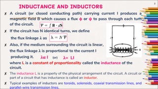
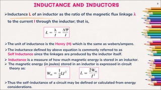
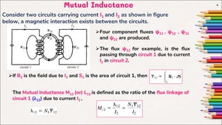
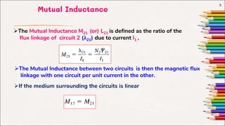
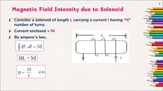
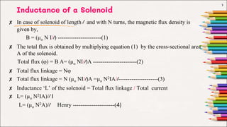
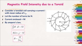
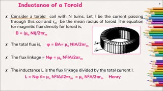
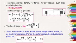
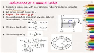


This document discusses inductance and inductors. It defines inductance as the ratio of magnetic flux linkage to current through an inductor. Typical inductors include solenoids, toroids, and coaxial cables. The document then provides formulas for calculating the inductance of these different types of inductors based on their geometry and number of turns. It also defines mutual inductance as the magnetic flux linkage in one circuit due to current in another circuit.


