

The document discusses UML (Unified Modeling Language) and object-oriented software development. It describes the software development life cycle and various modeling techniques used in UML, including use case diagrams, class diagrams, sequence diagrams, and collaboration diagrams. It explains key UML concepts such as classes, objects, attributes, operations, actors, and relationships. The benefits of visual modeling and UML are also summarized.
Introduction to Unified Modeling Language (UML) by Ch. Vishwa Mohan, Project Manager.
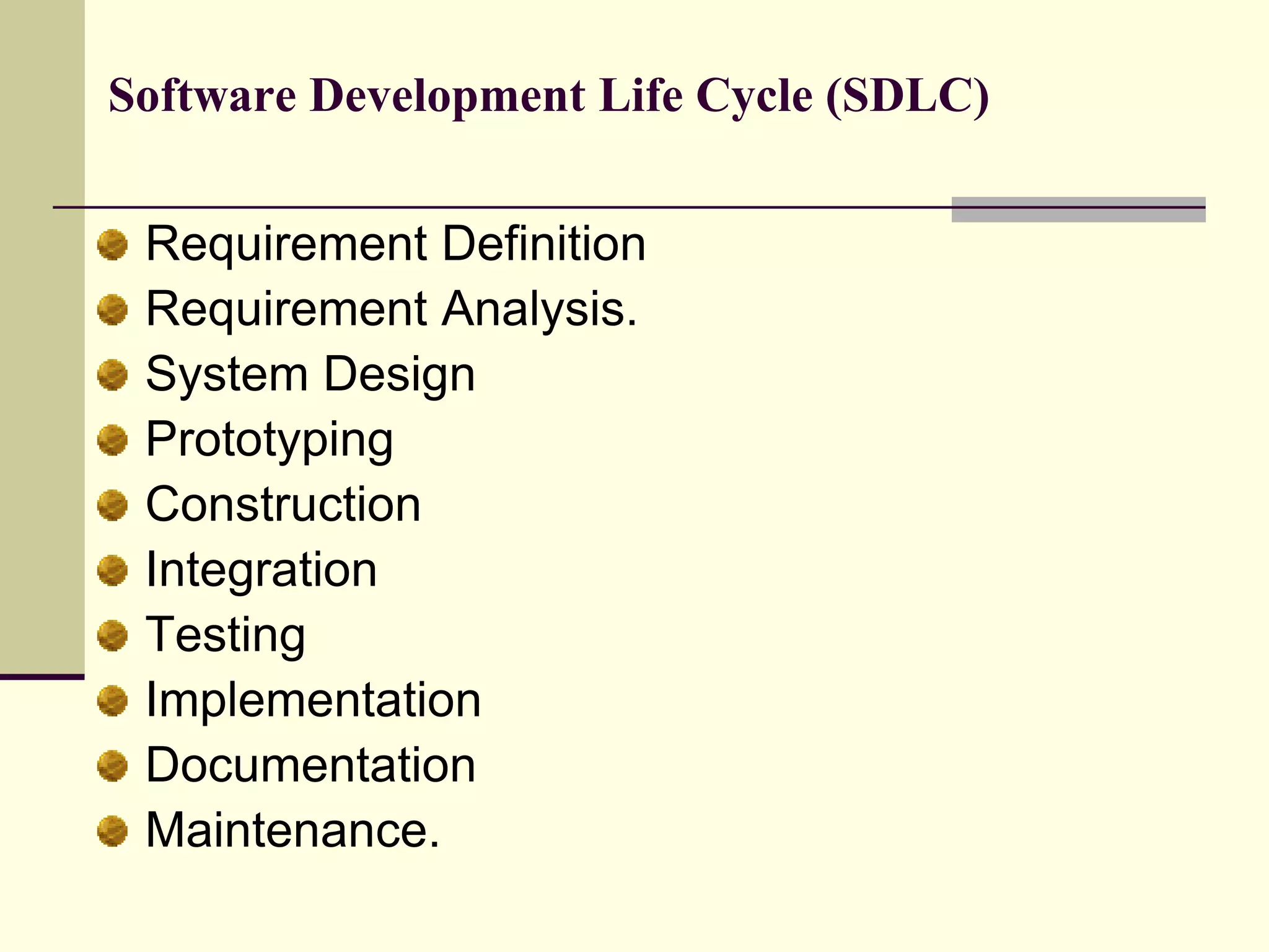
Overview of the Software Development Life Cycle (SDLC) phases including Requirement Definition, Design, Prototyping, and Maintenance.
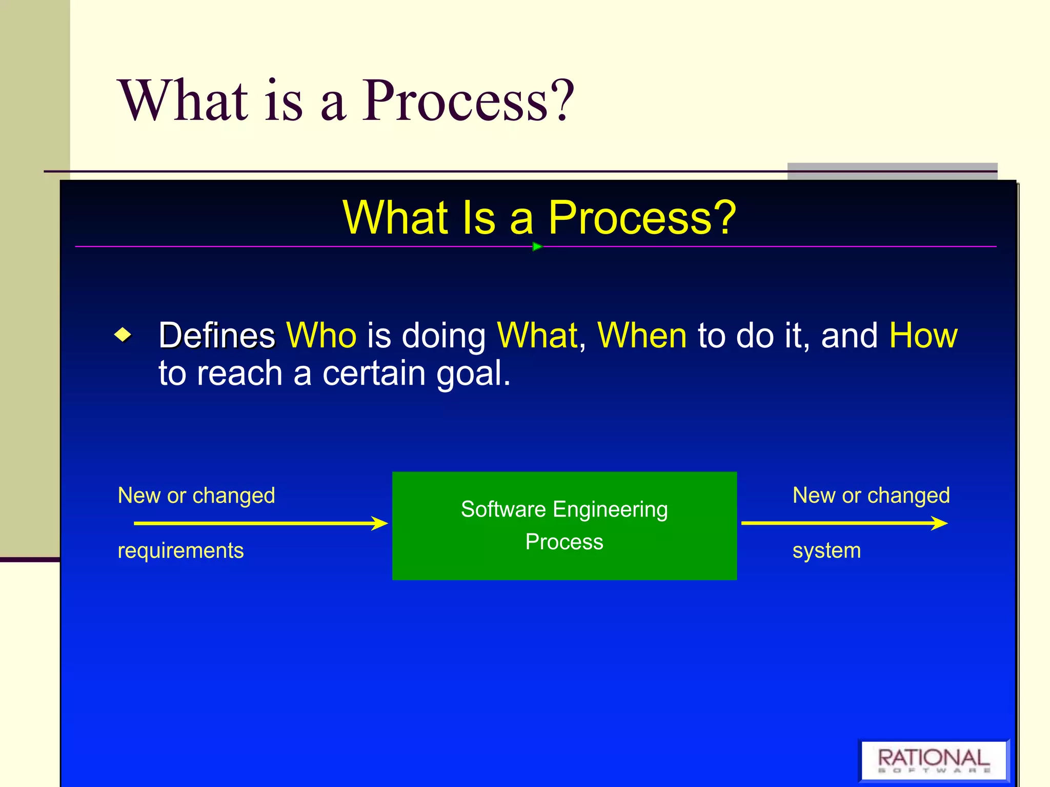
Explains the concept of a process in systems development.
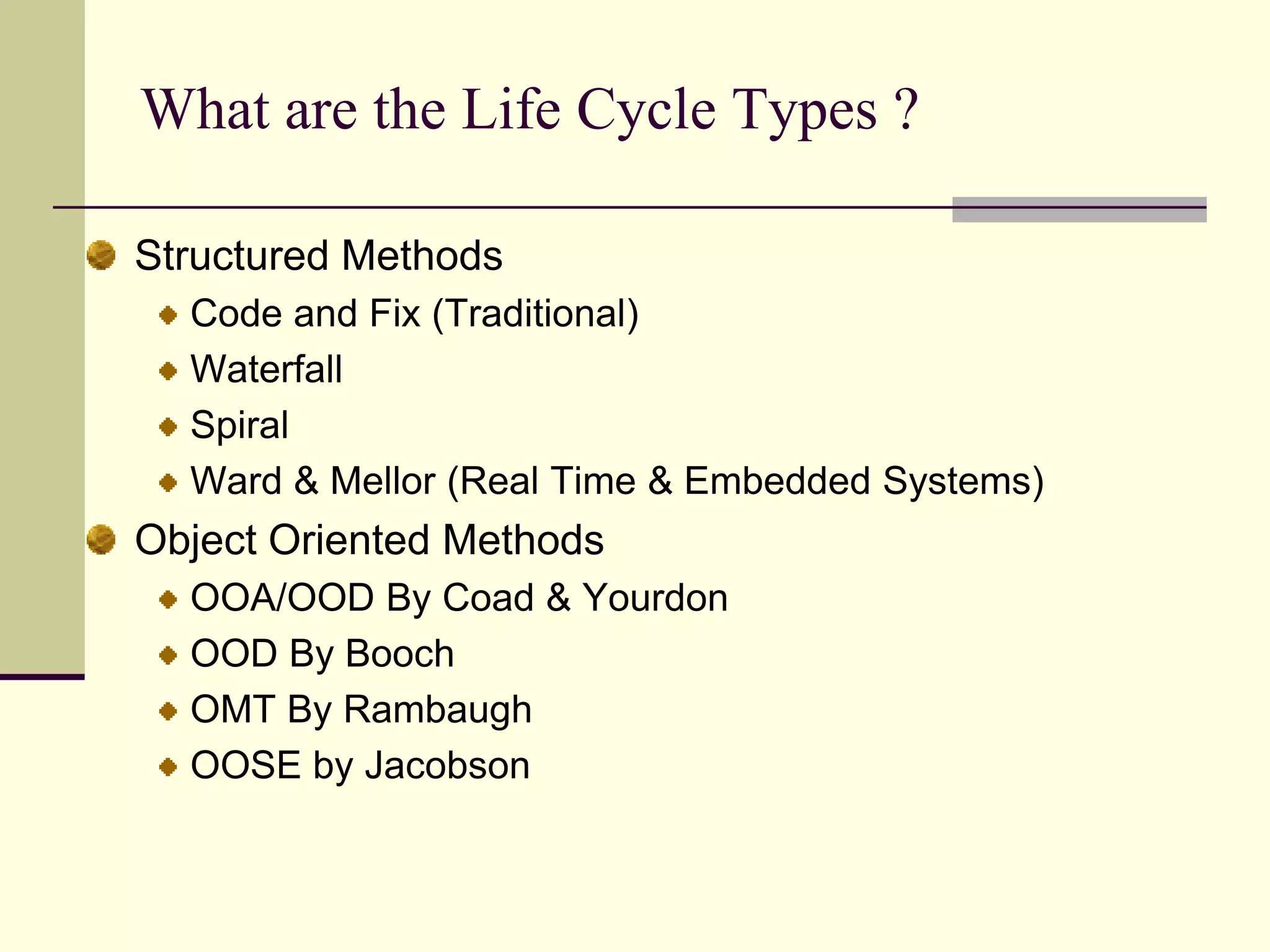
Describes various life cycle types including Structured Methods, Waterfall, and Object Oriented methods.
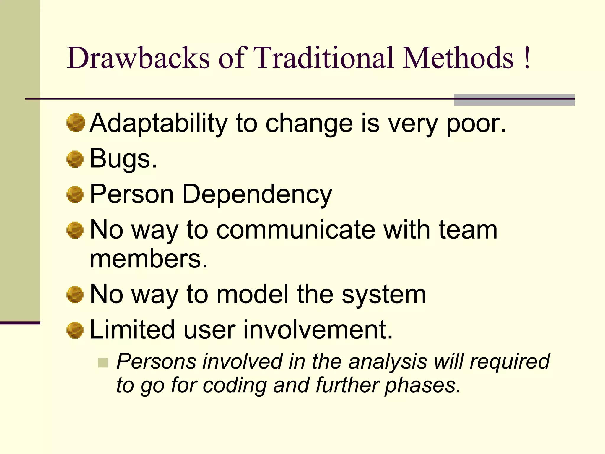
Highlights disadvantages of traditional software methodologies such as poor adaptability and limited user involvement.
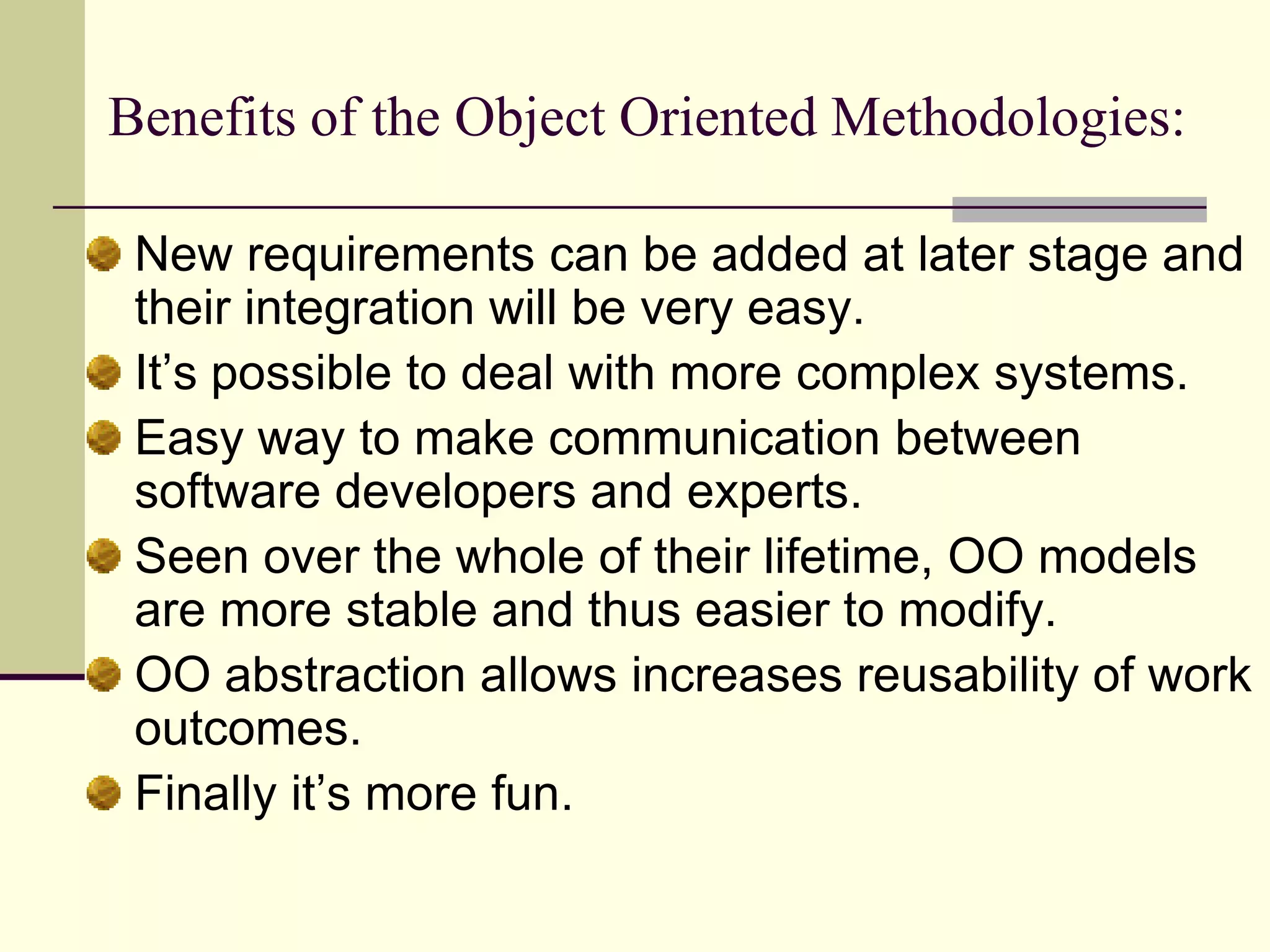
Lists advantages of Object Oriented methodologies including easier modification, stability, and communication.
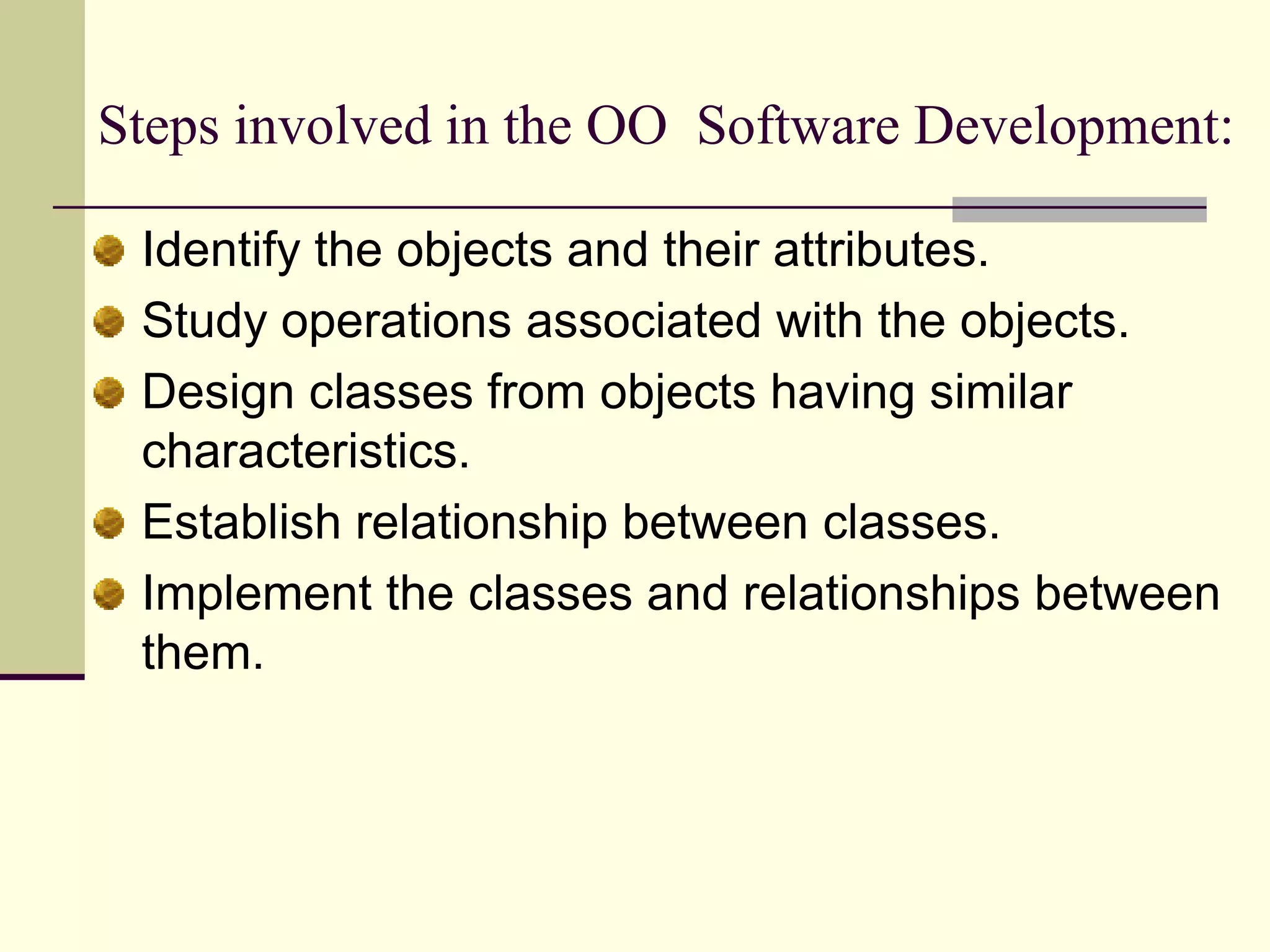
Details the process steps in Object Oriented Software Development like identifying objects, designing classes, and establishing relationships.
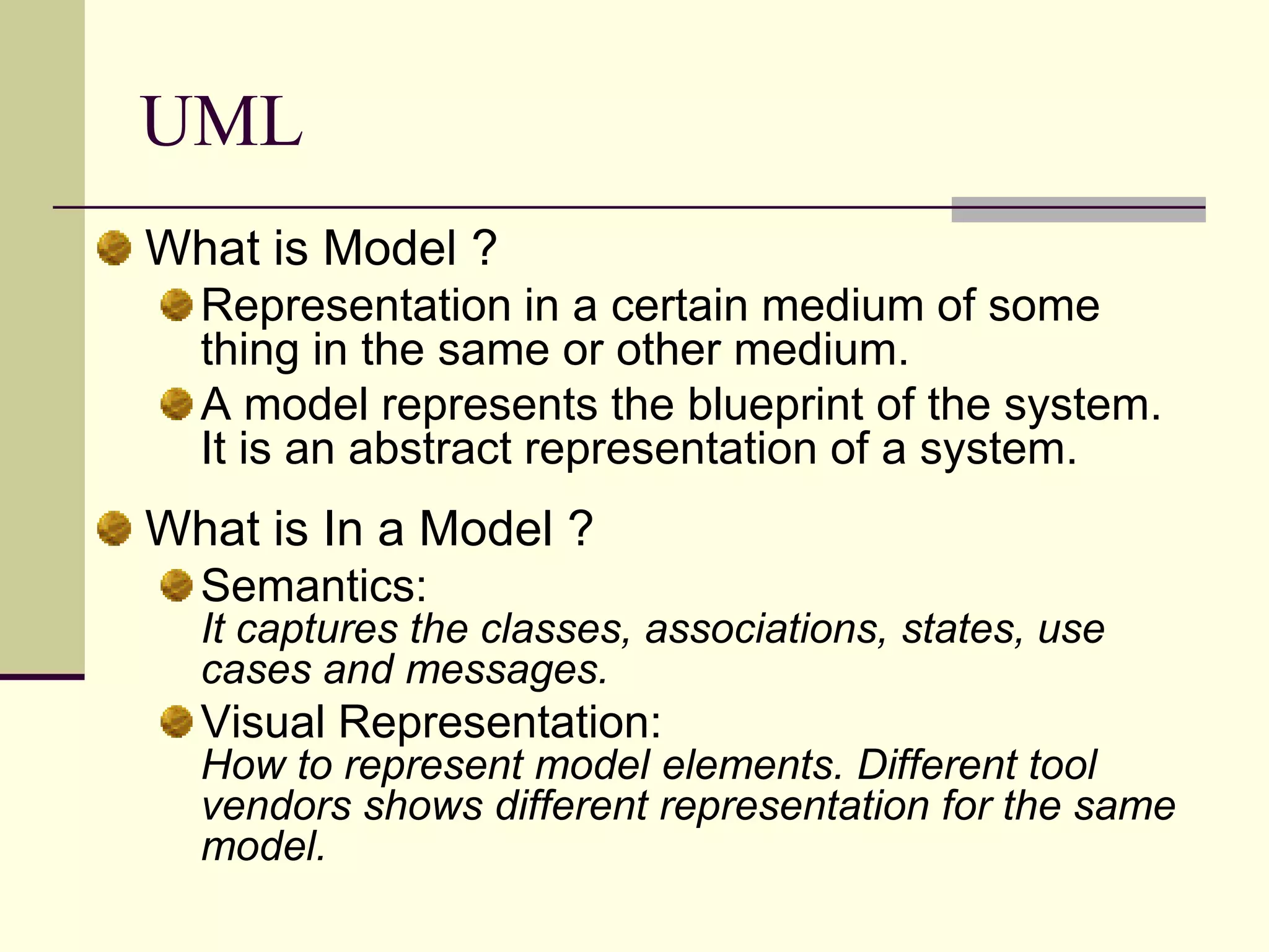
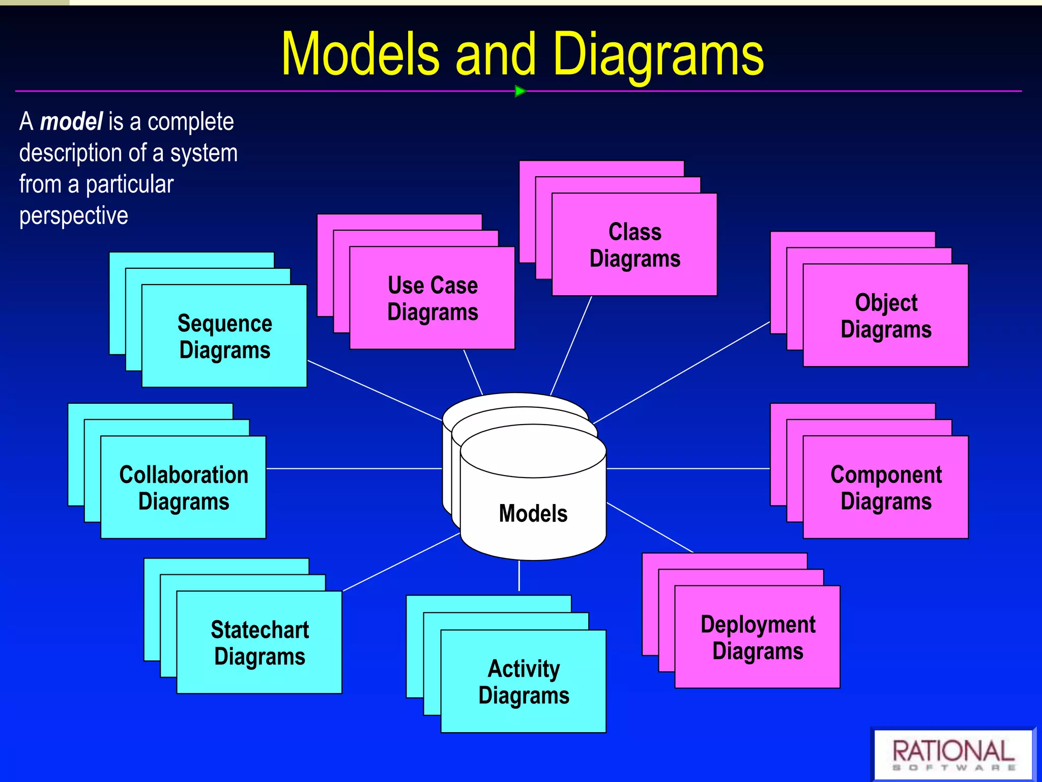
Defines a model in the context of software systems, including its representation and semantics.
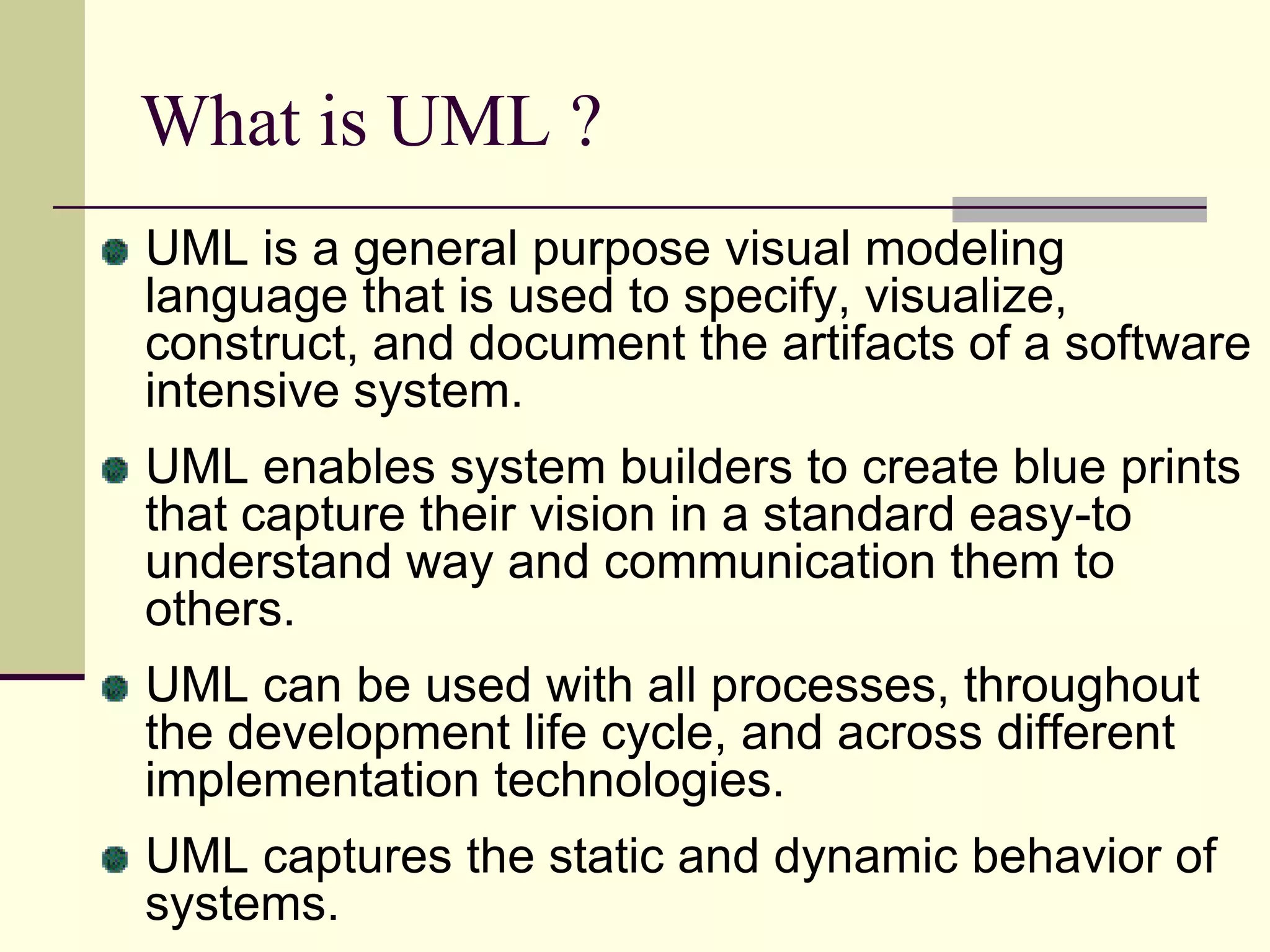
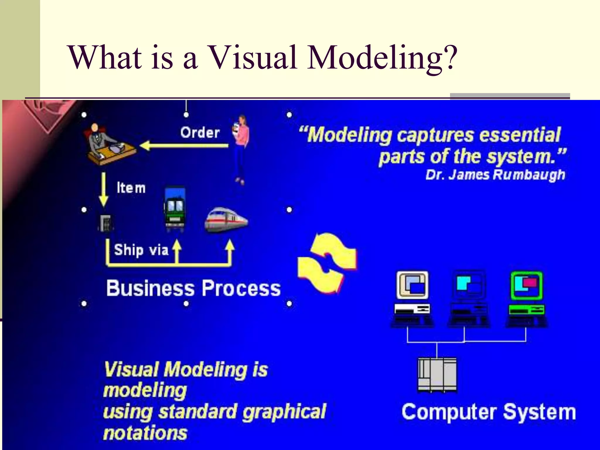
Describes UML as a visual modeling language for software systems used to create blueprints capturing system specifications.
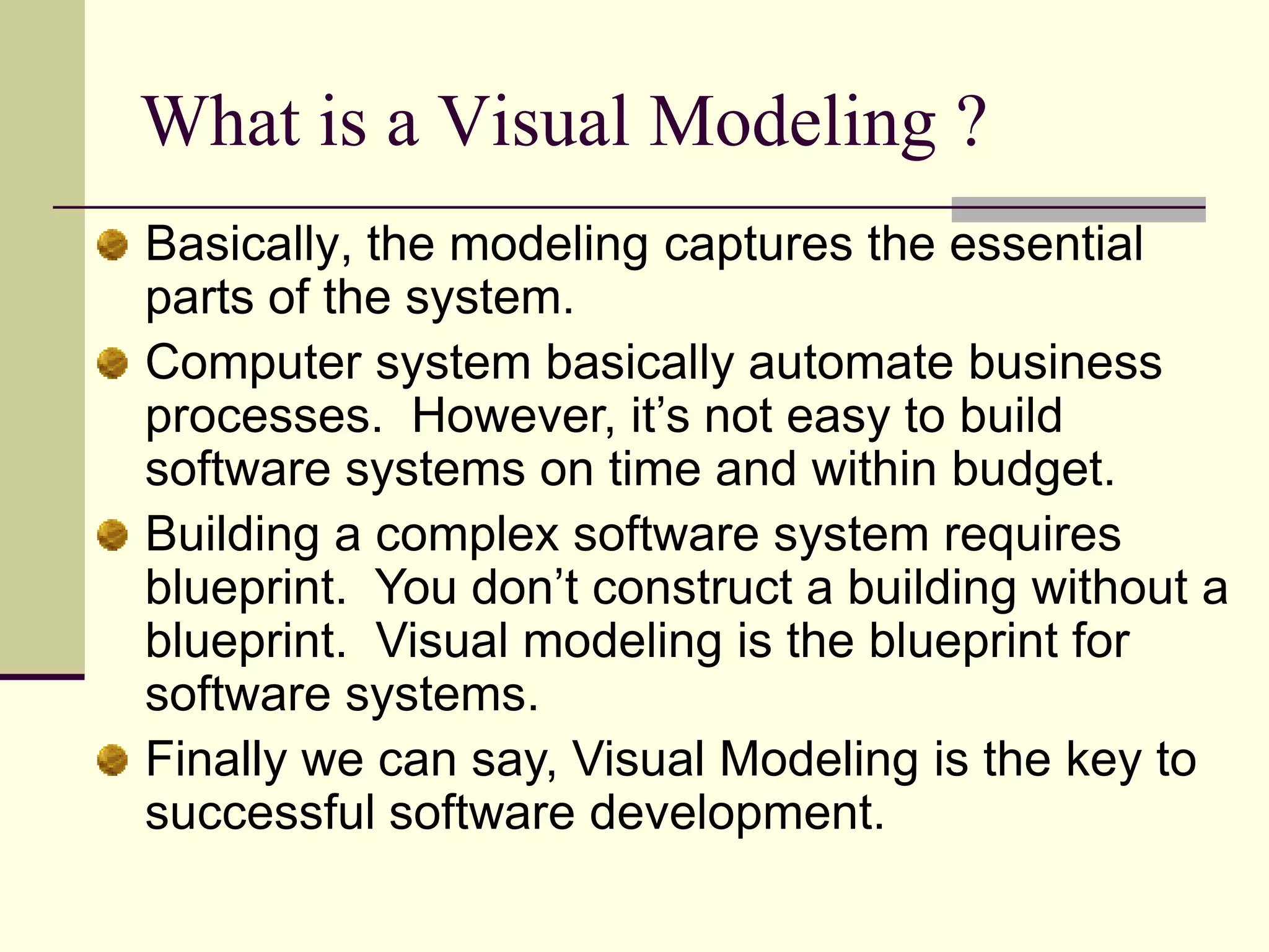
Explains visual modeling as crucial for successful software development, emphasizing the importance of blueprints.
Further elaboration on visual modeling in the context of software systems.
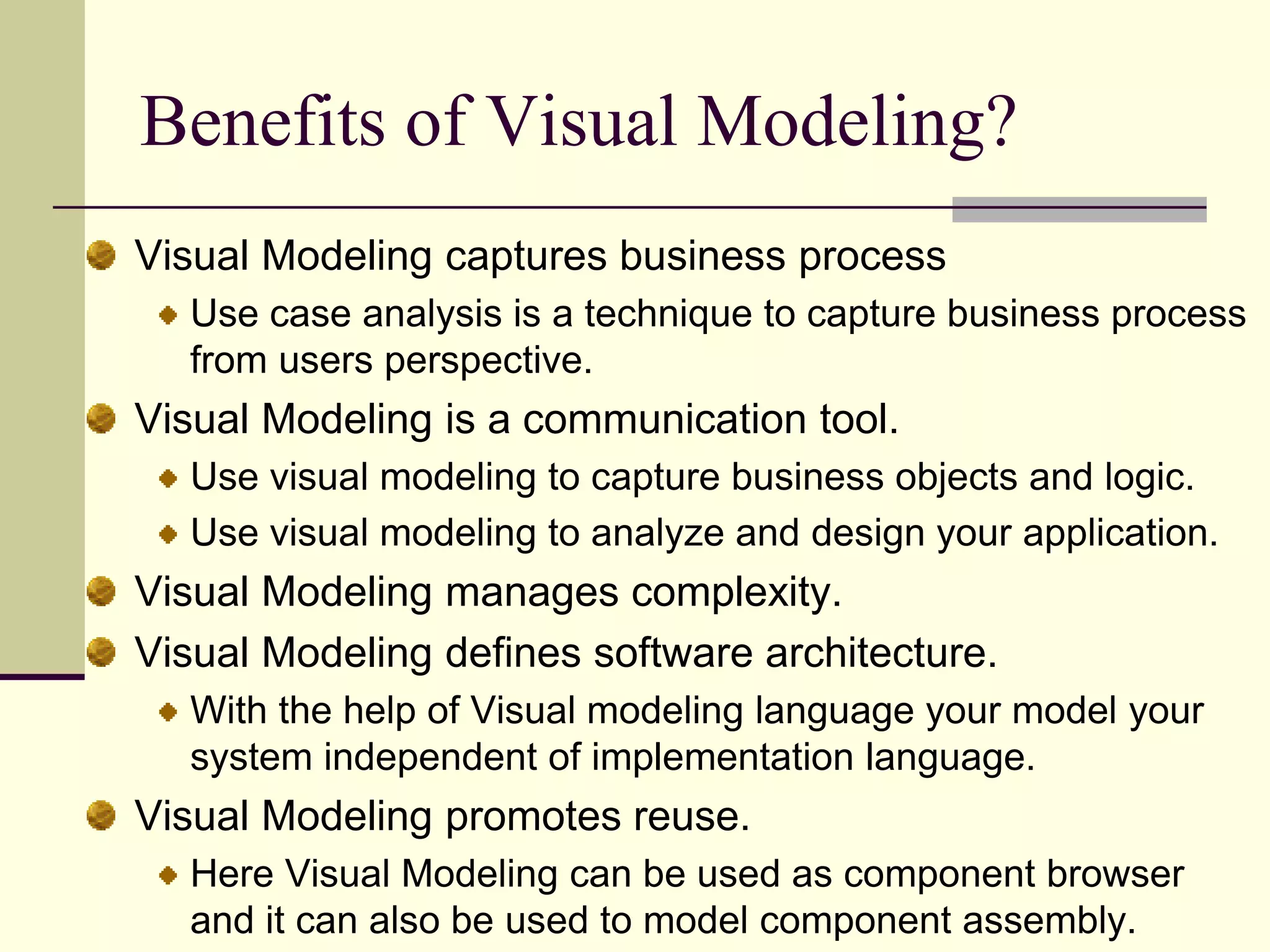
Enumerates benefits of visual modeling including complexity management, architecture definitions, and promoting reuse.
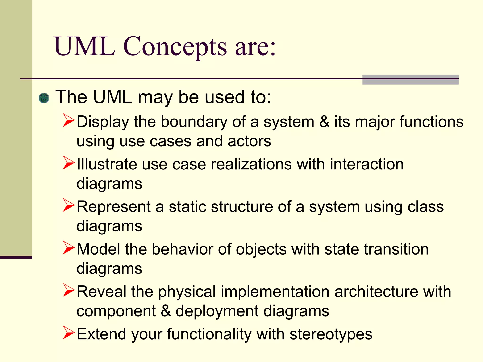
Discusses various UML concepts including use cases, class diagrams, and static vs dynamic behaviors.
Explains how UML aids in Object Oriented software development by defining relationships among data and functions.
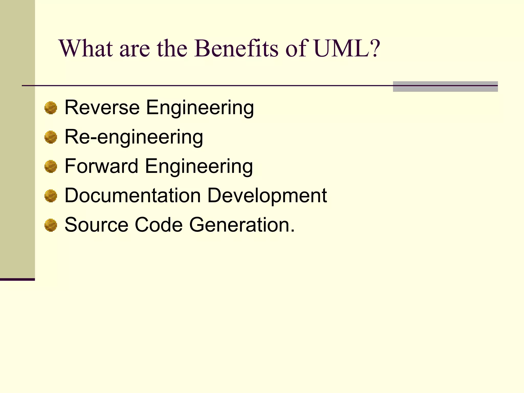
Outlines benefits of using UML including reverse engineering, documentation development, and source code generation.
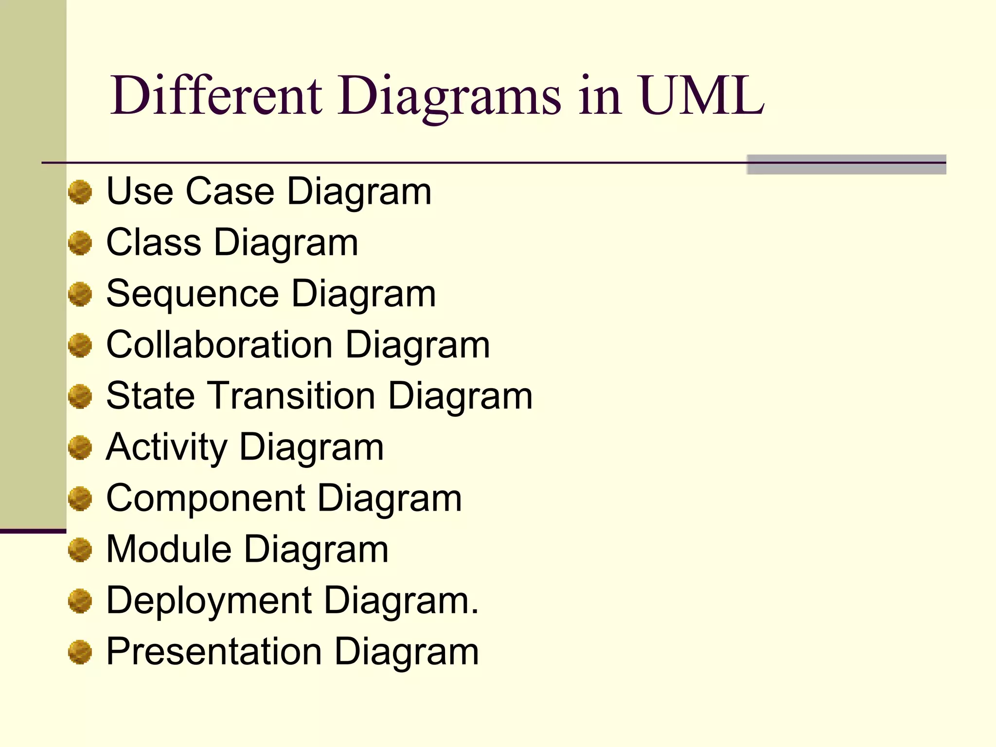
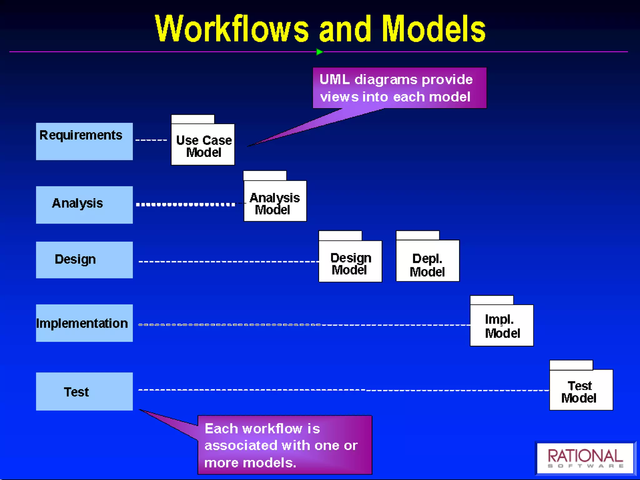
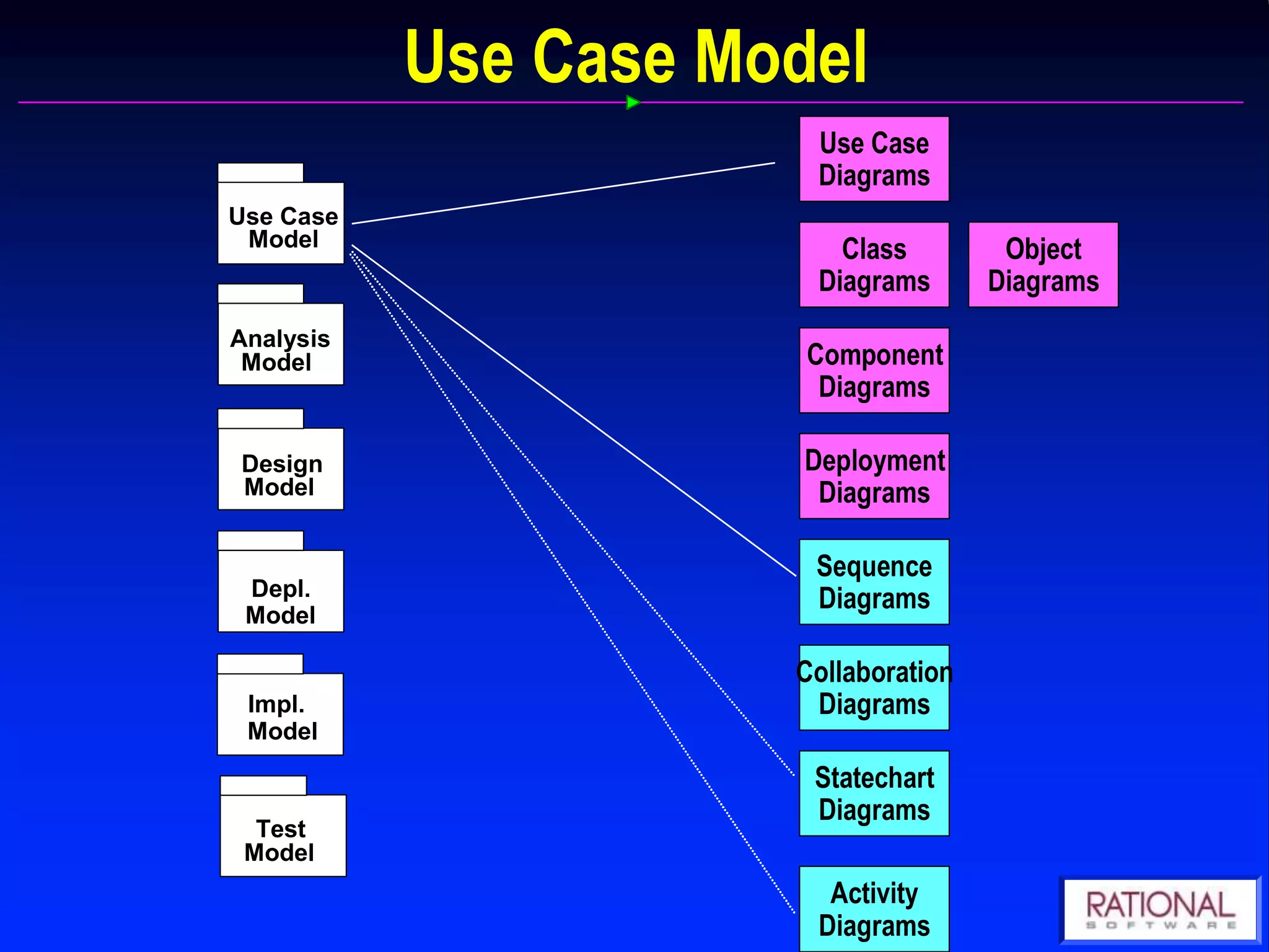
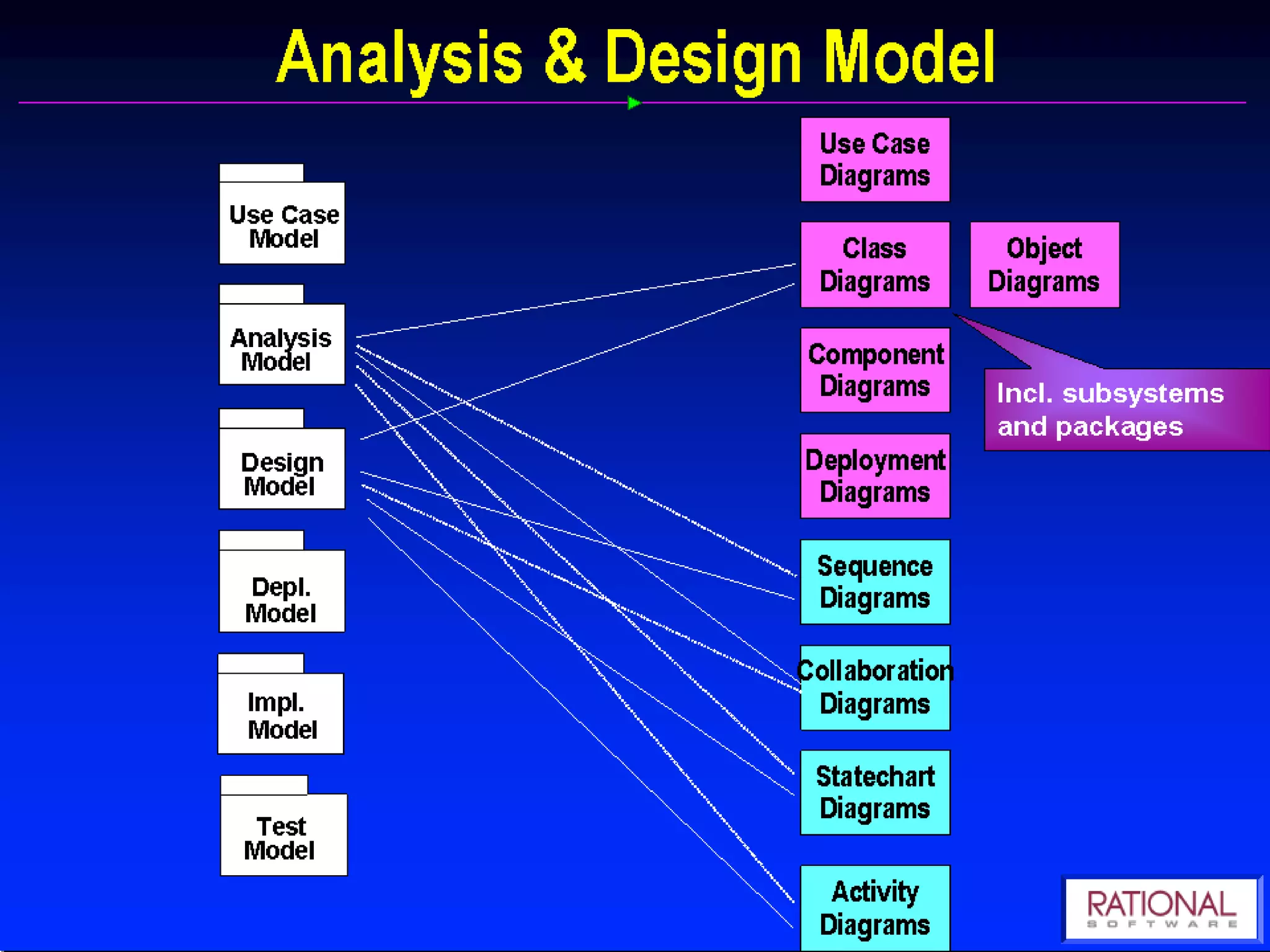
Lists various diagram types in UML crucial for modeling software systems like Use Case and Class Diagrams.
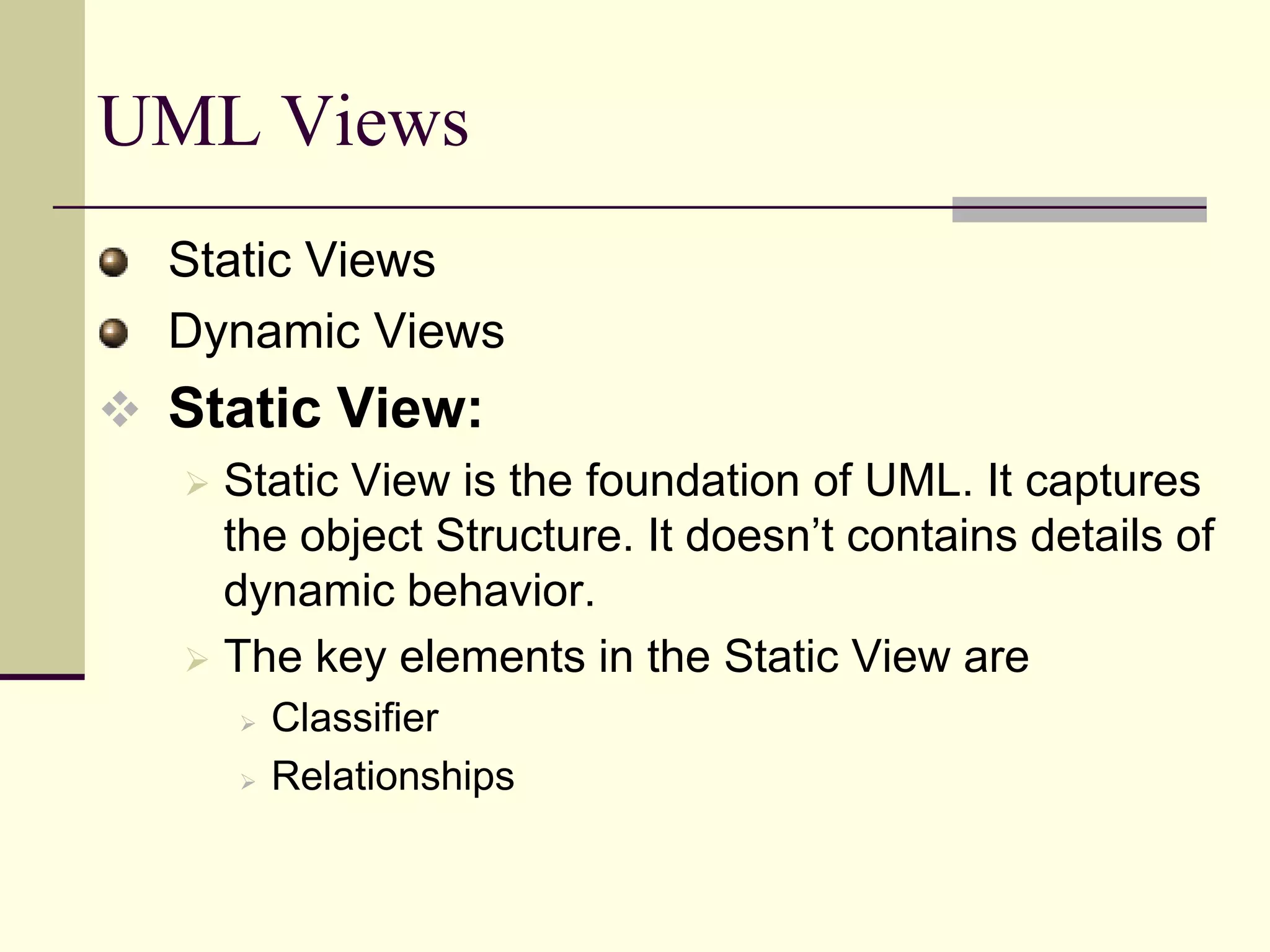
Describes static and dynamic views in UML, highlighting the importance of capturing object structures.
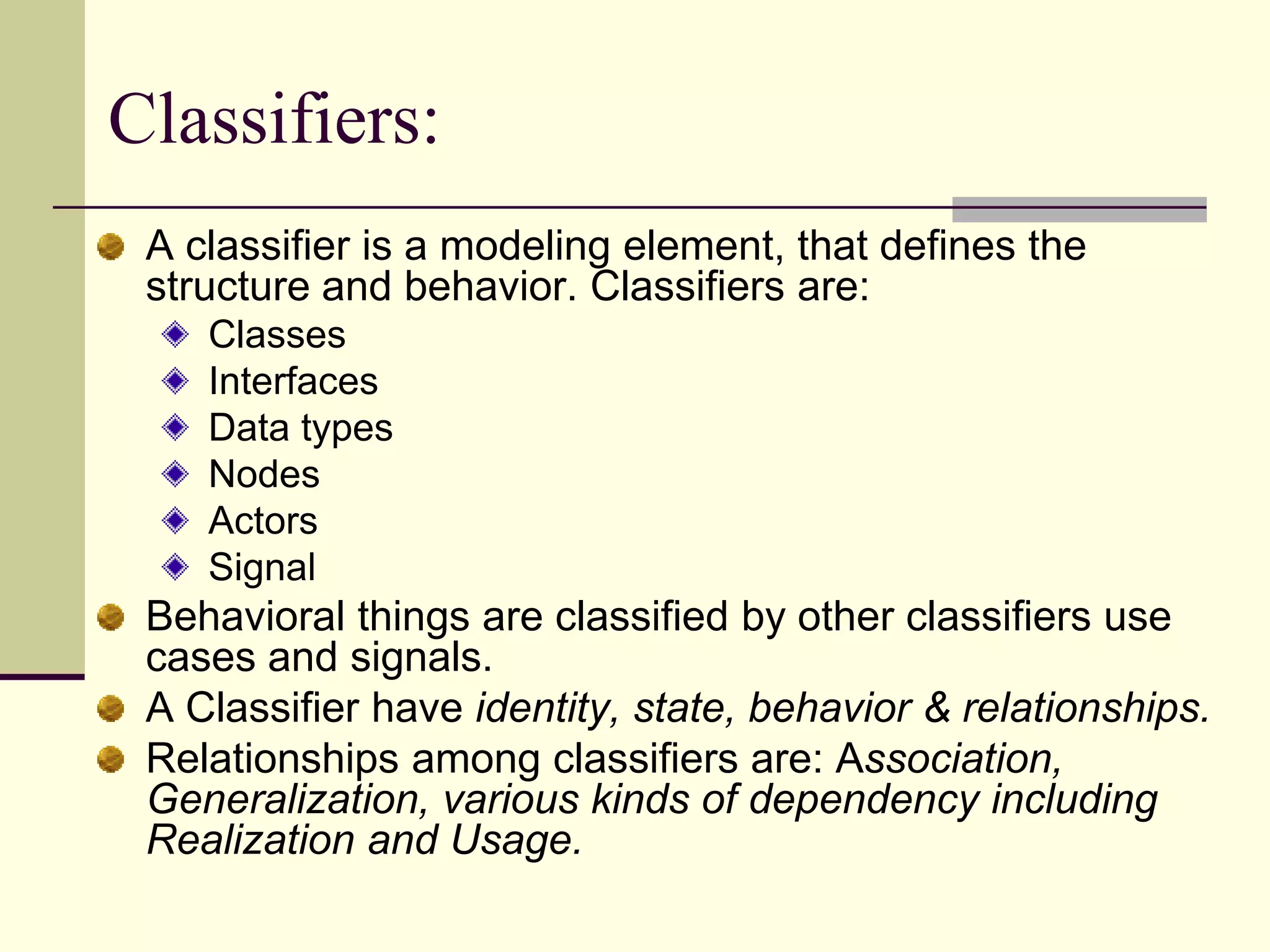
Defines classifiers in UML and discusses various types and their relationships.
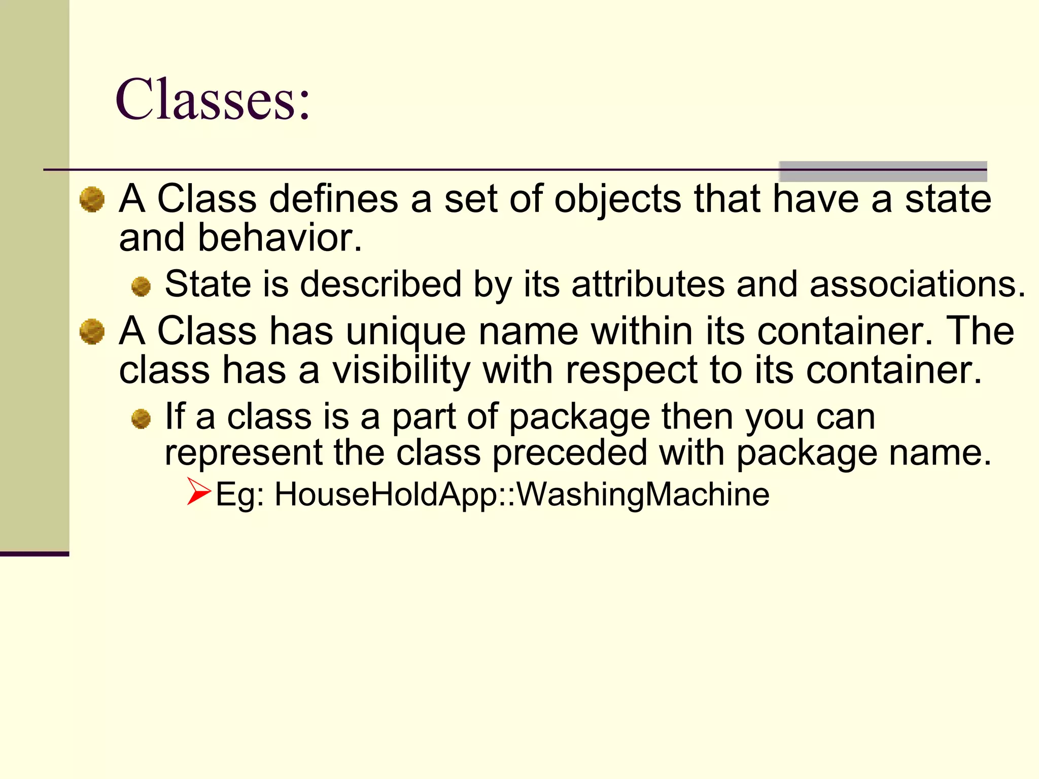
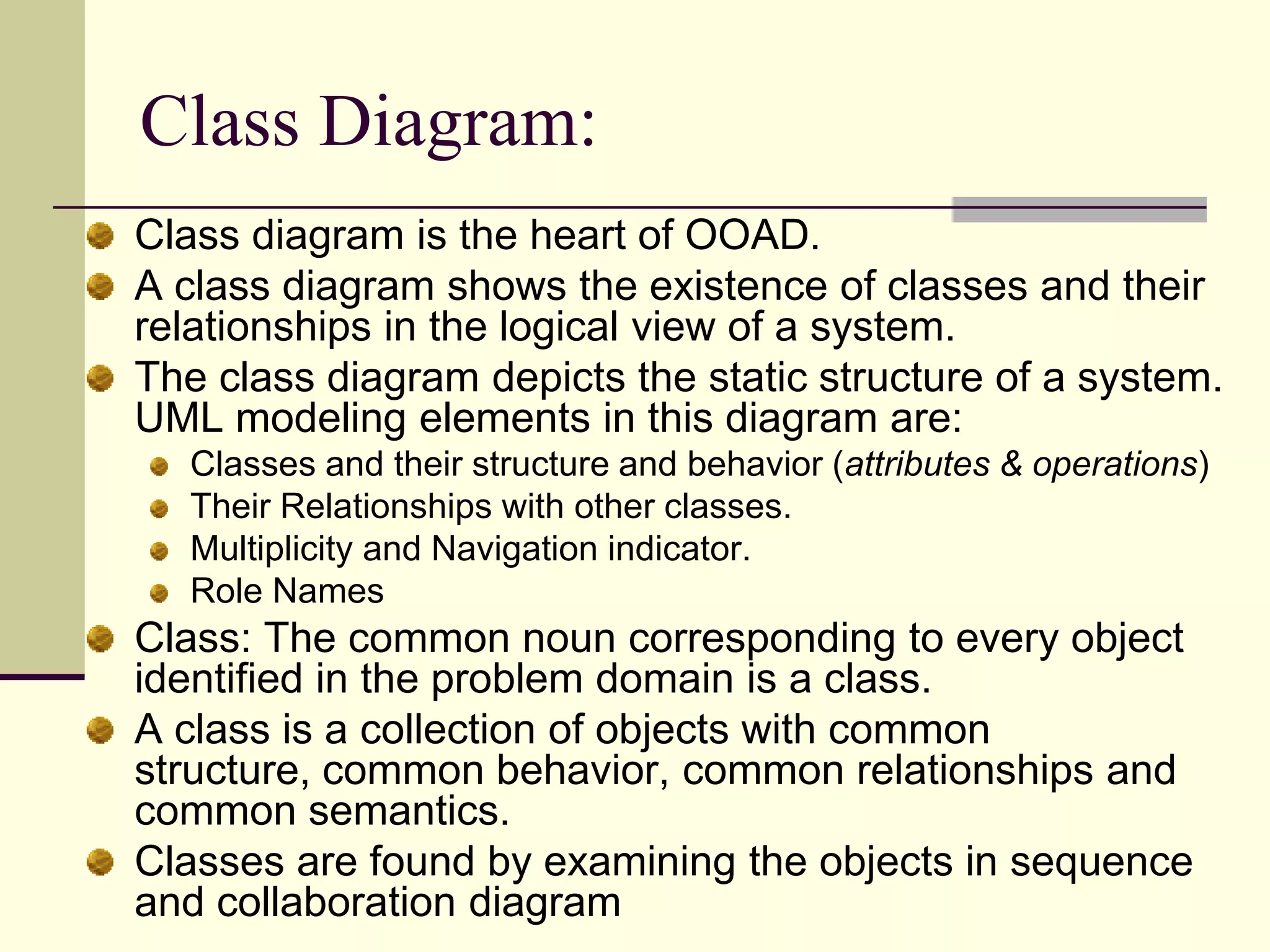
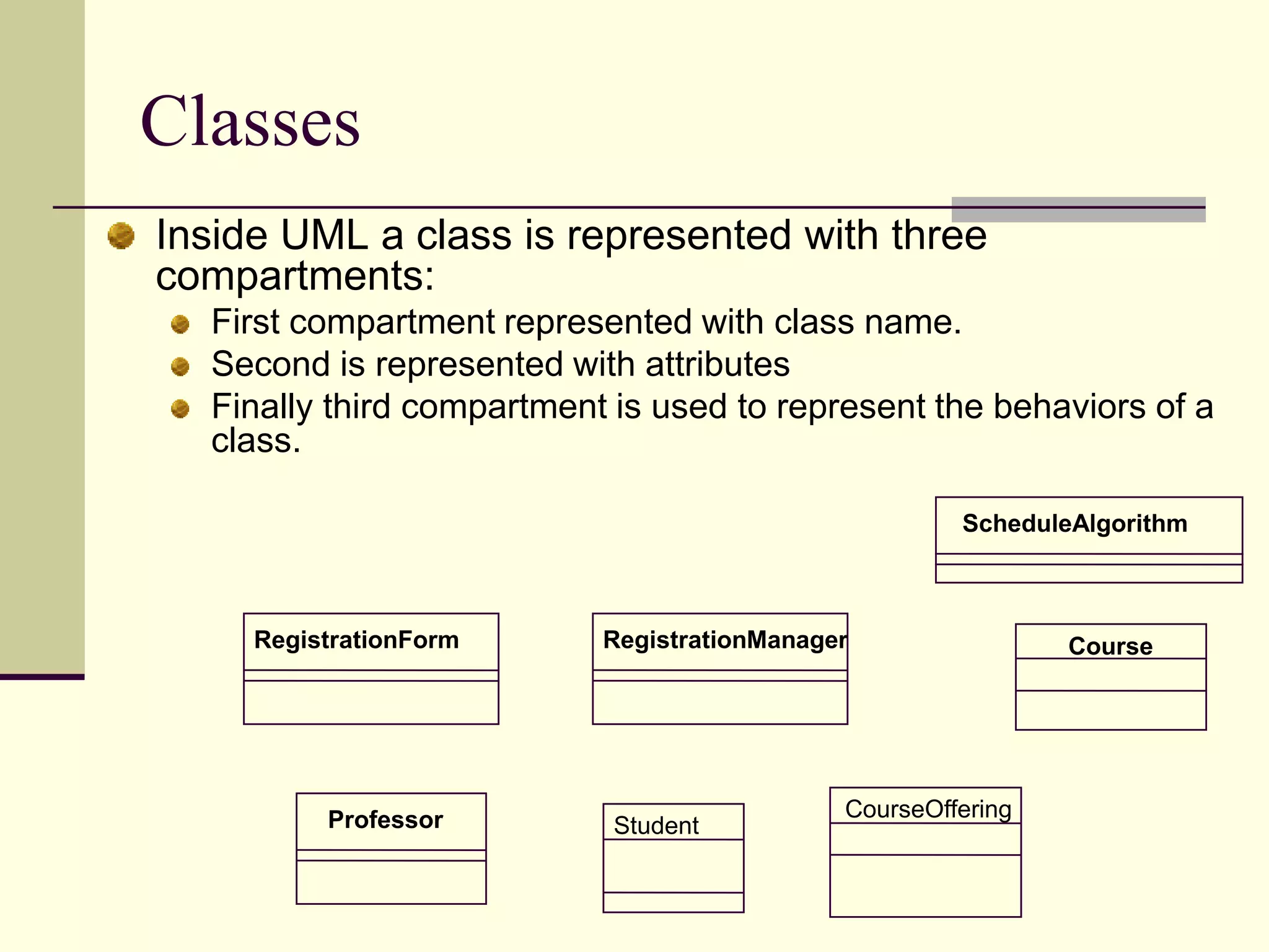
Describes the concept of classes in UML, their attributes, and behavior.
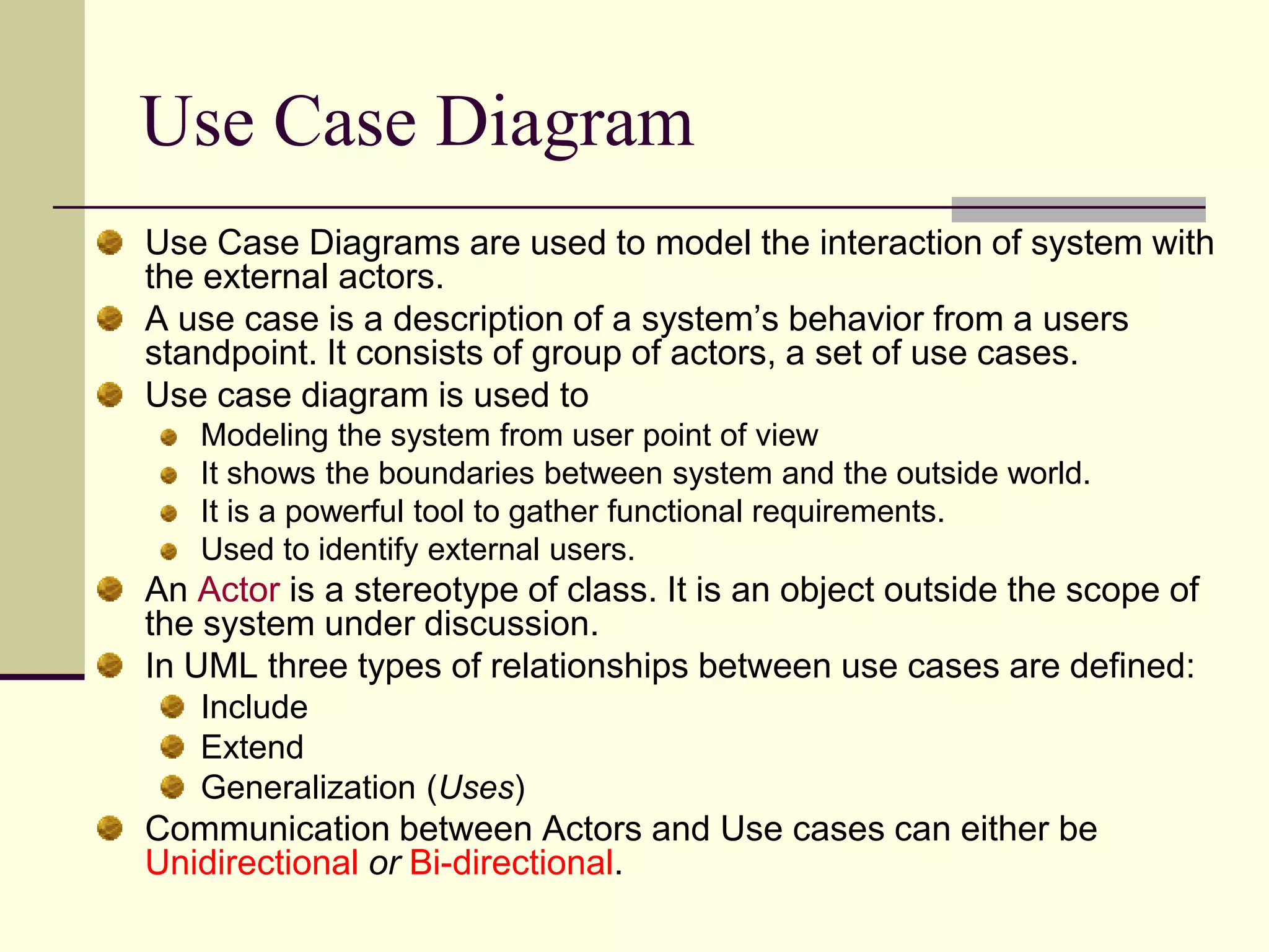
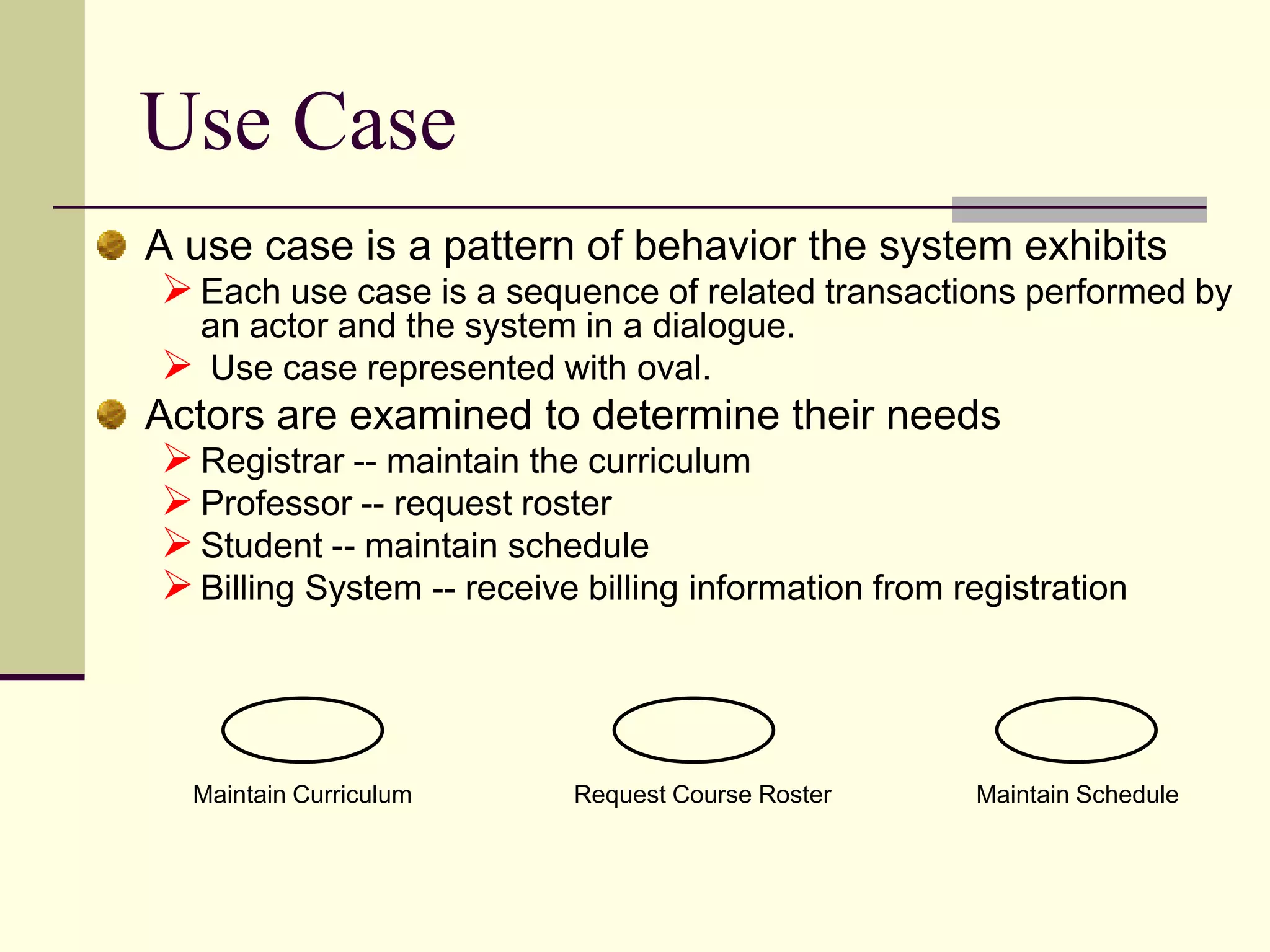
Details use case diagrams, modeling interactions between systems and external actors.
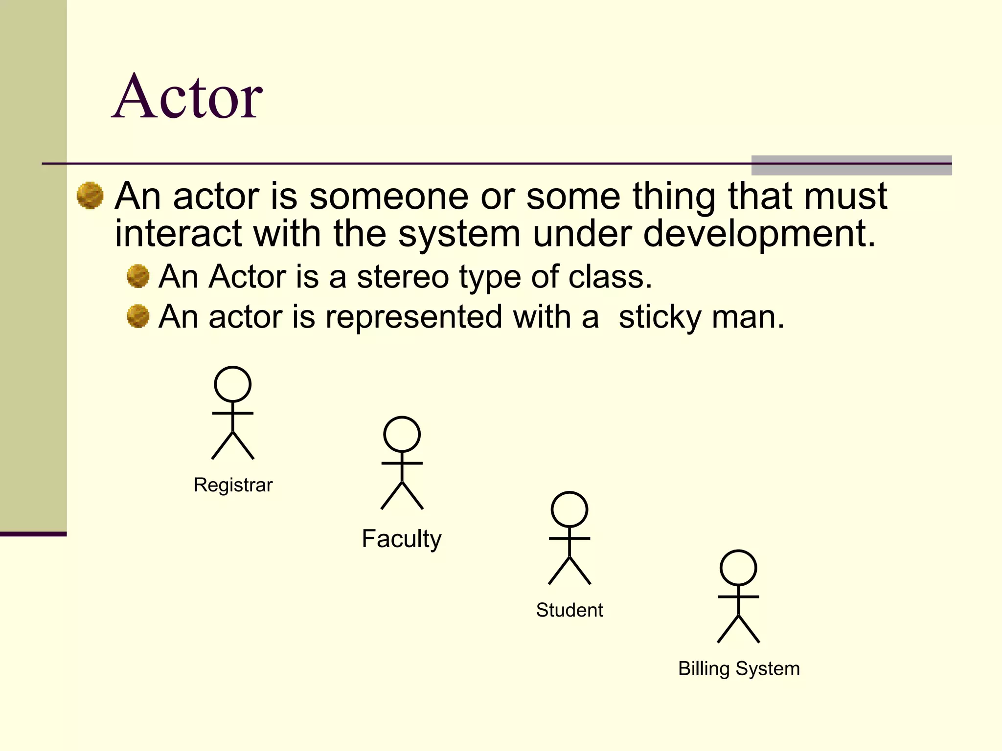
Describes the role of actors in use case diagrams and their representation.
Defines use cases and their role in depicting system behavior involving user interactions.
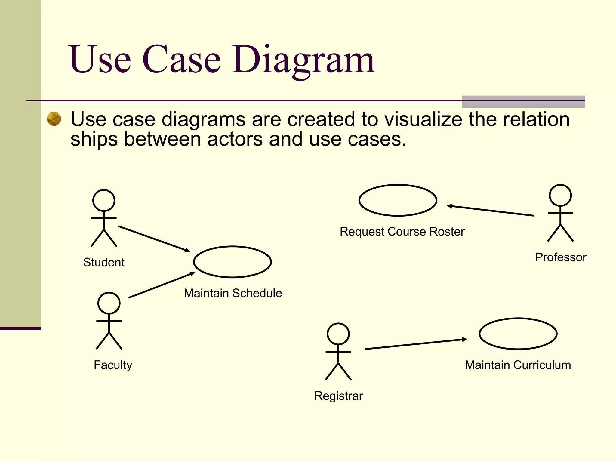
Illustrates relationships in use case diagrams among actors and use cases.
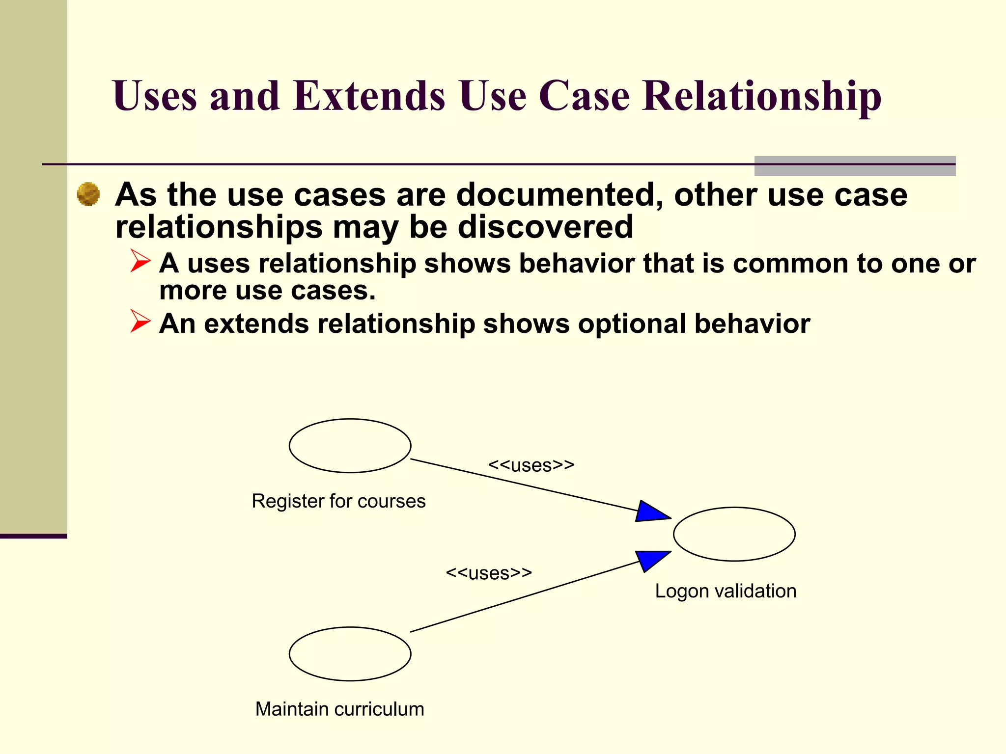
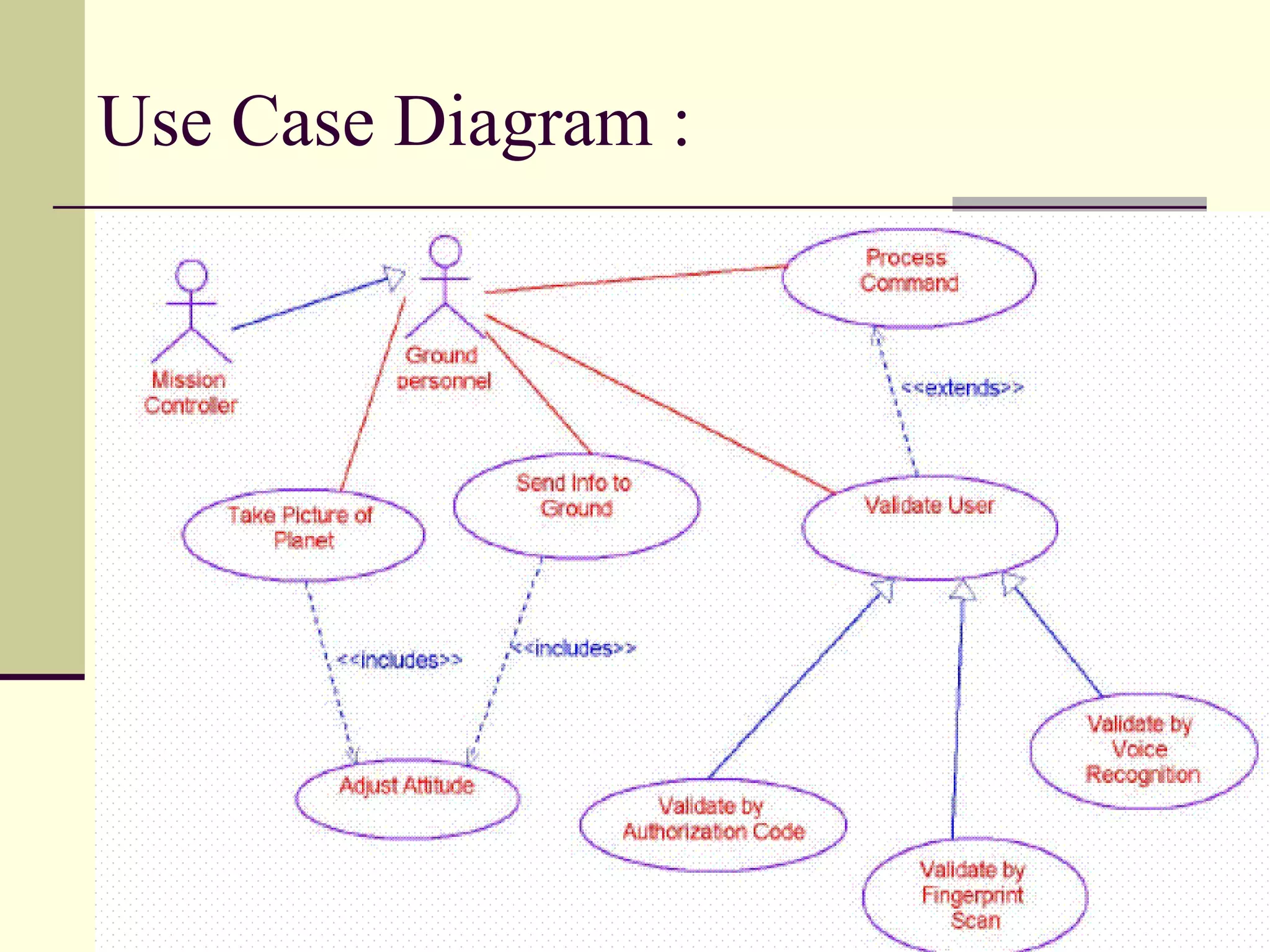
Explains different use case relationships such as ‘uses’ and ‘extends‘ in UML.
Visual representation of a use case diagram to illustrate interactions.
Describes how use cases are realized through interaction diagrams.
Details the importance of class diagrams in Object Oriented Analysis and Design (OOAD).
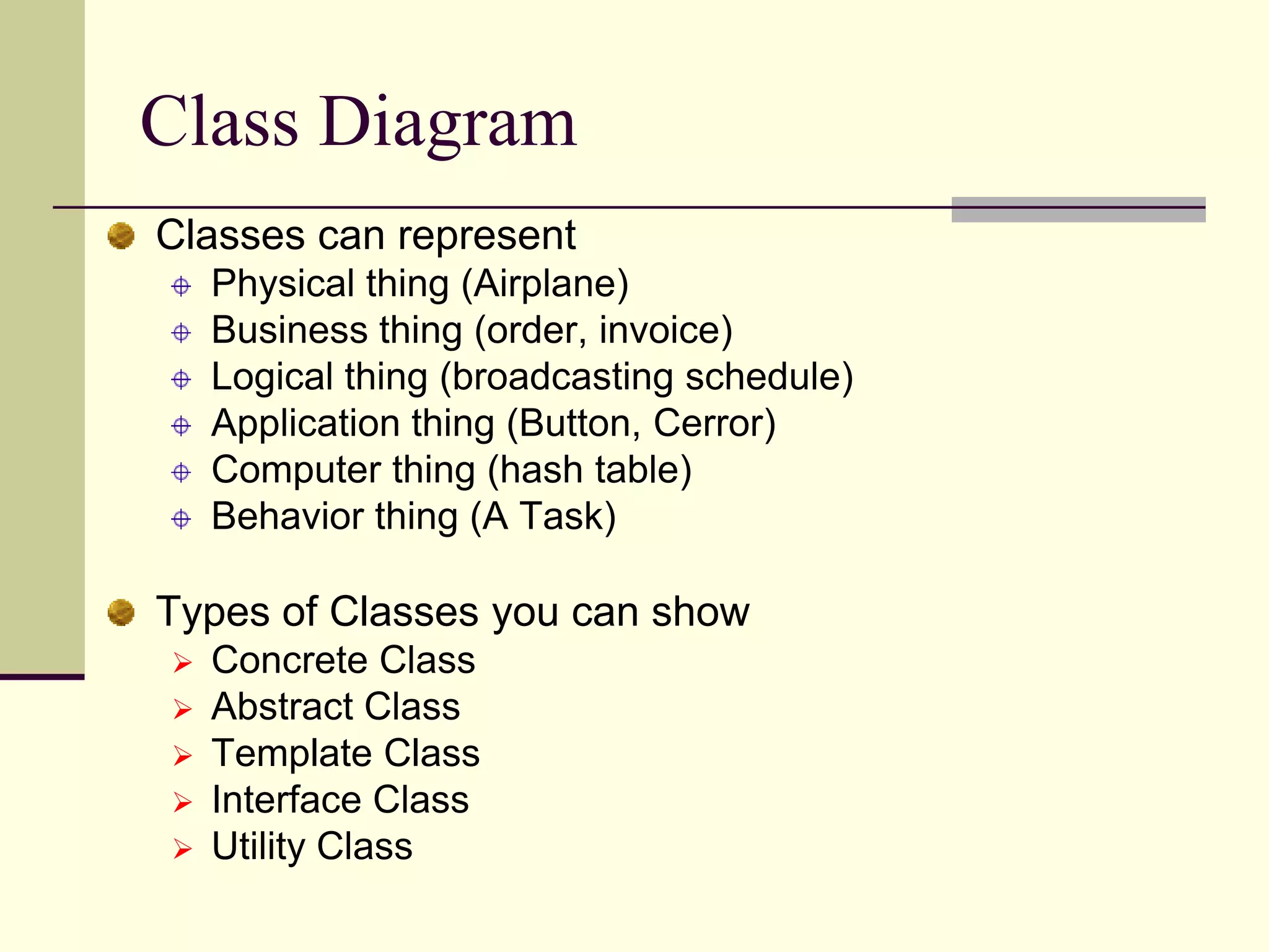
Enumerates different class types that can be represented including Abstract and Interface classes.
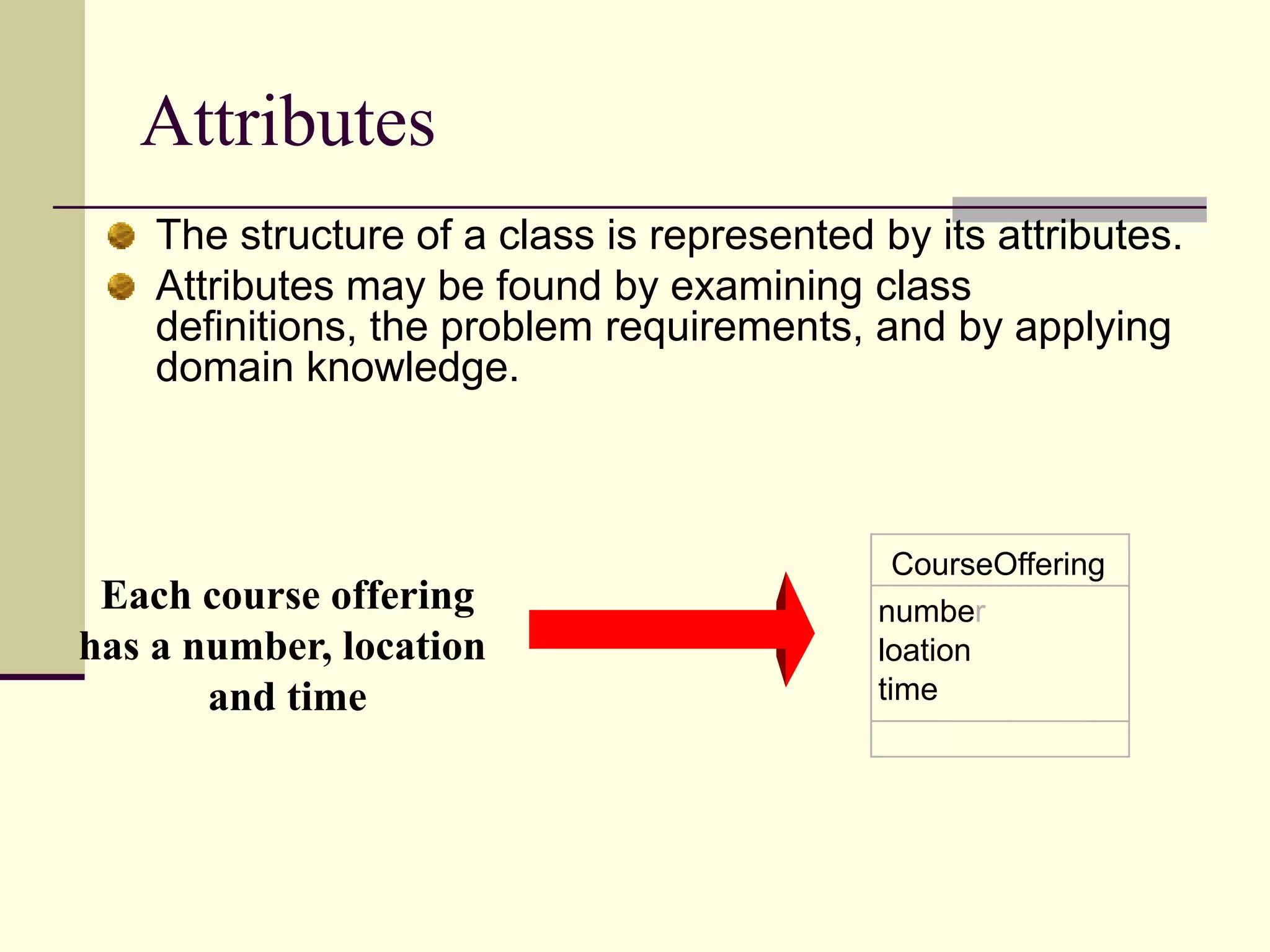
Discusses class structure representation focusing on attributes.
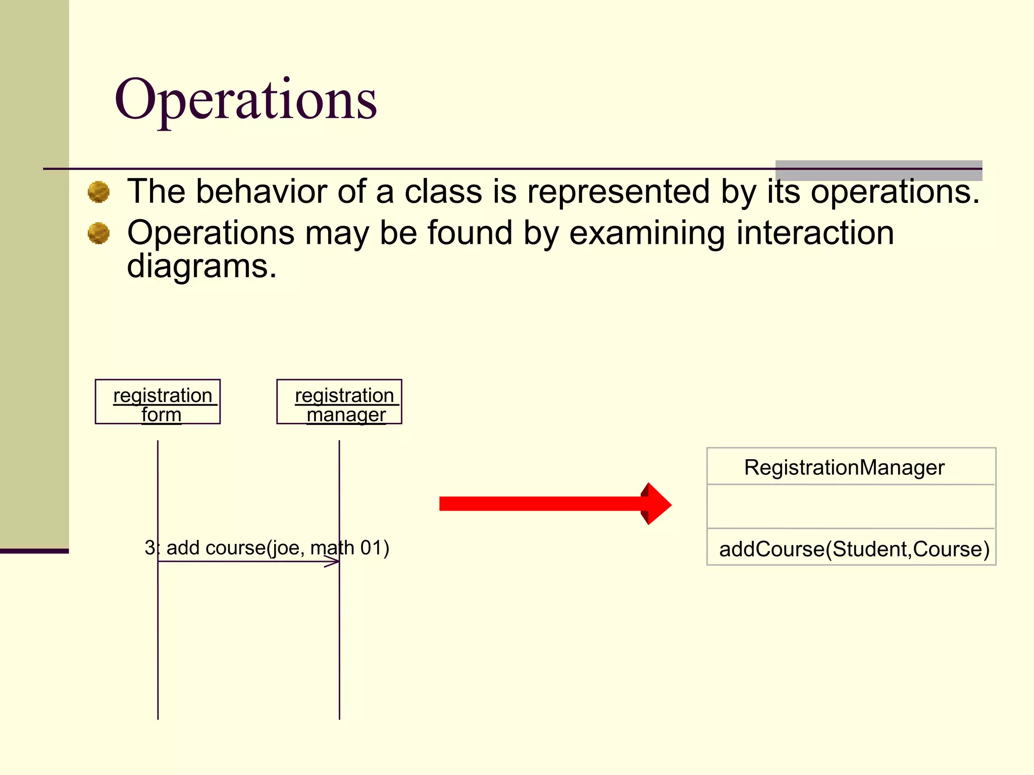
Describes how class behavior and operations are represented in UML.
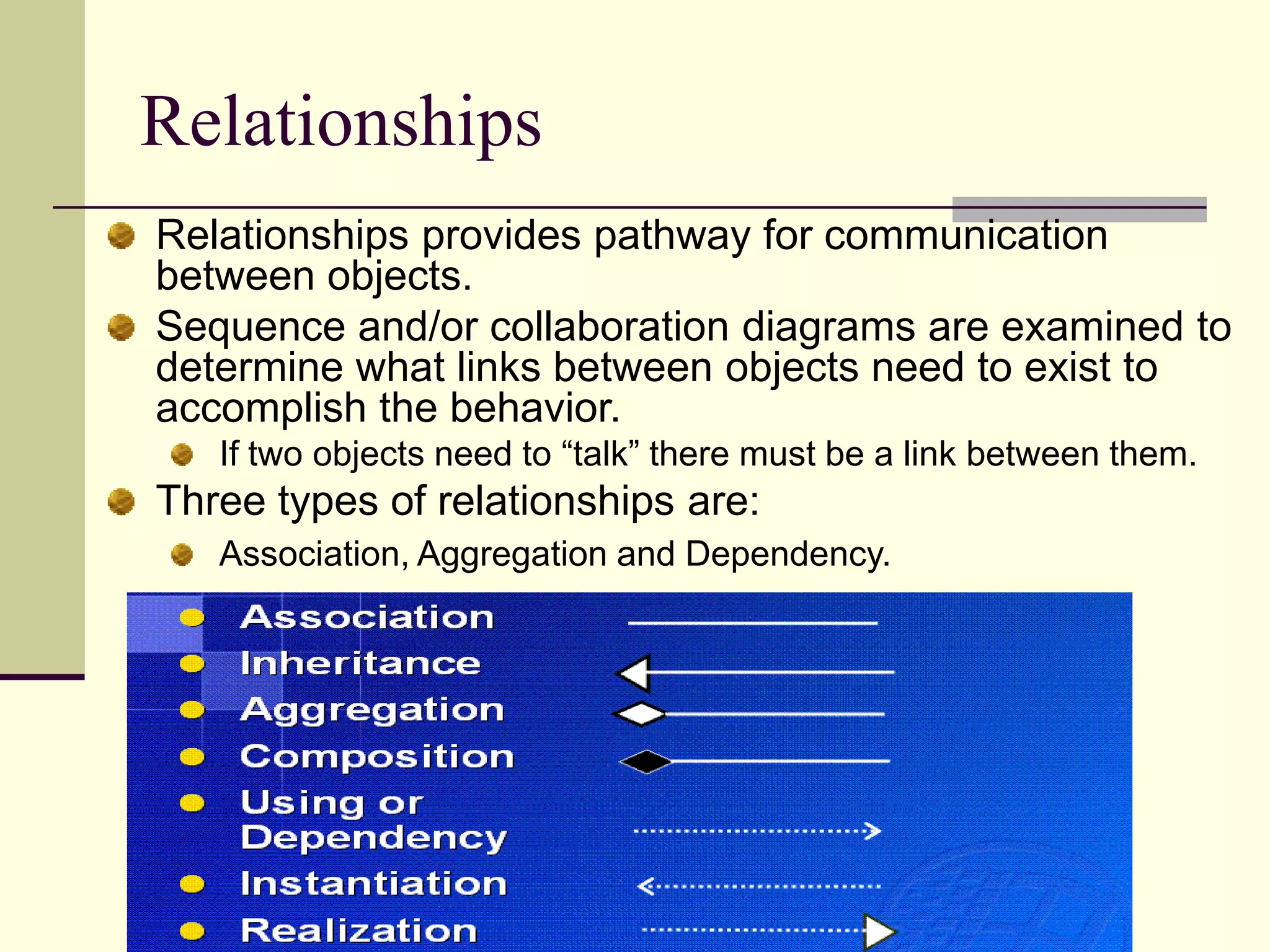
Explains the role of relationships in UML including association, aggregation, and dependency.
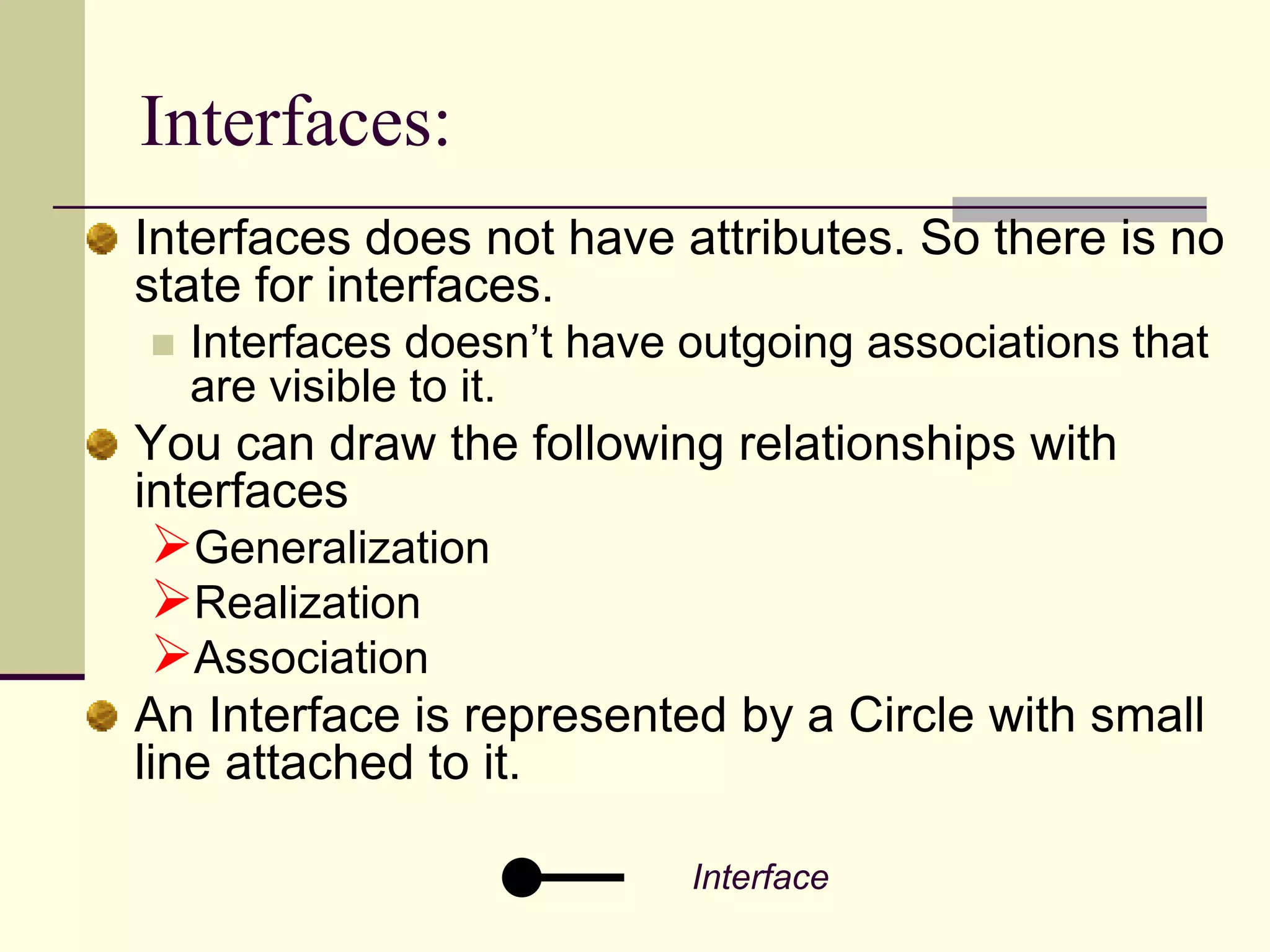
Defines the concept of interfaces in UML and their relationships to classes.
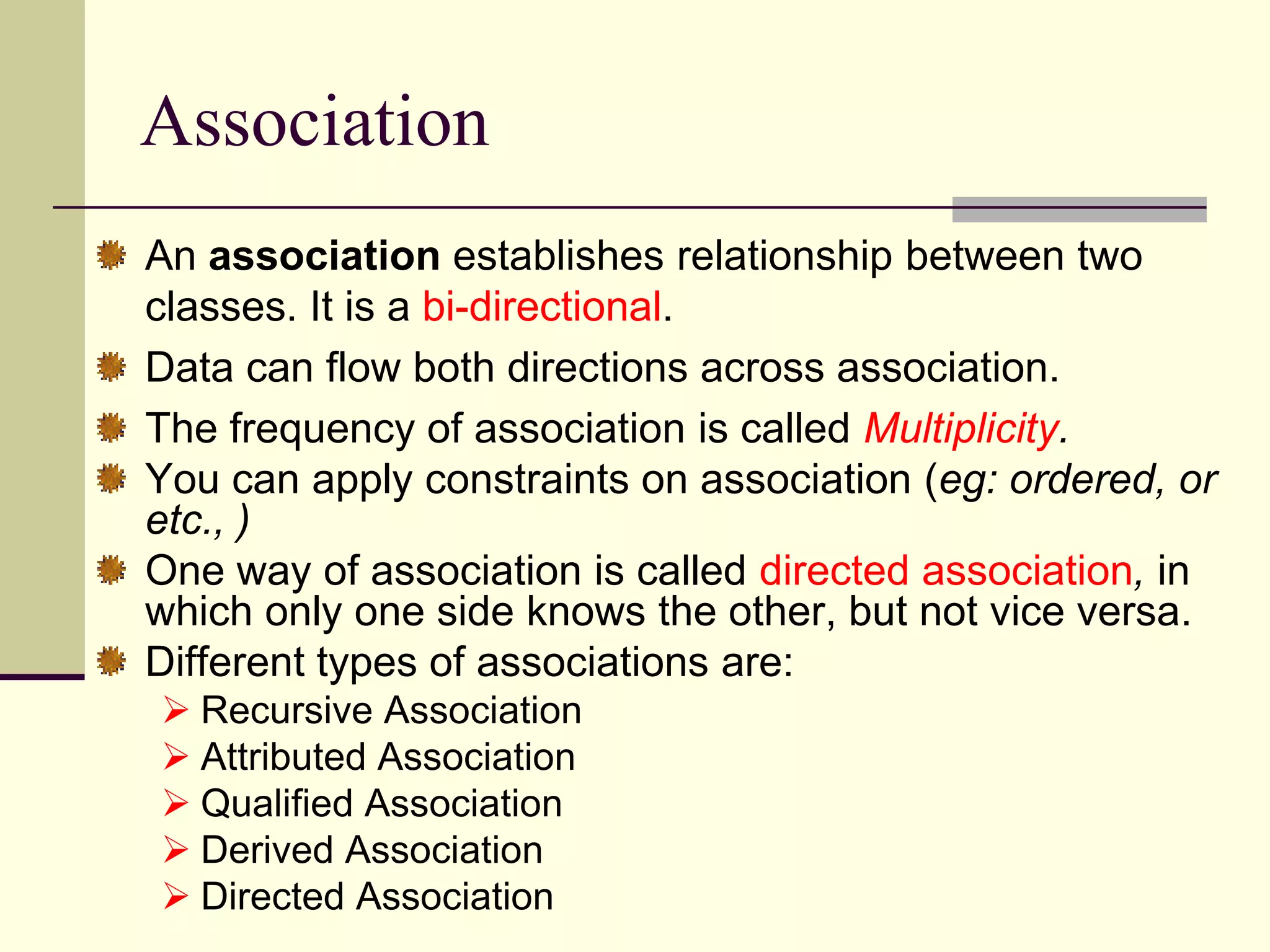
Describes how associations are established in UML to create links between classes.
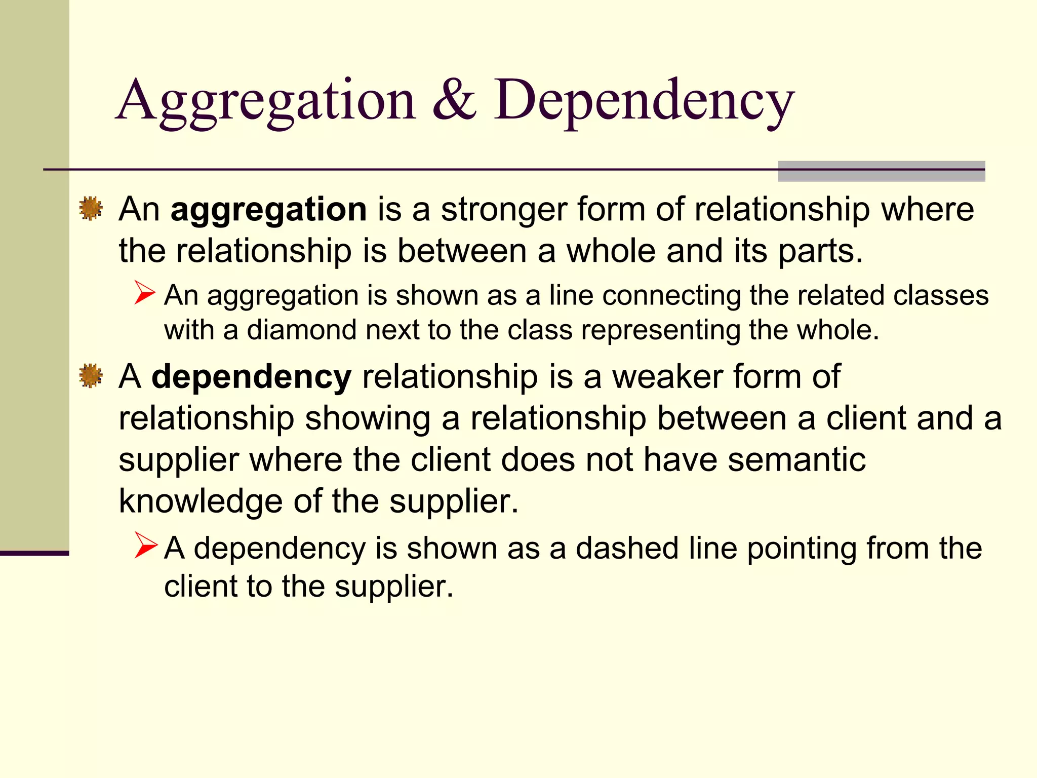
Differentiates between aggregation and dependency relationships in UML.
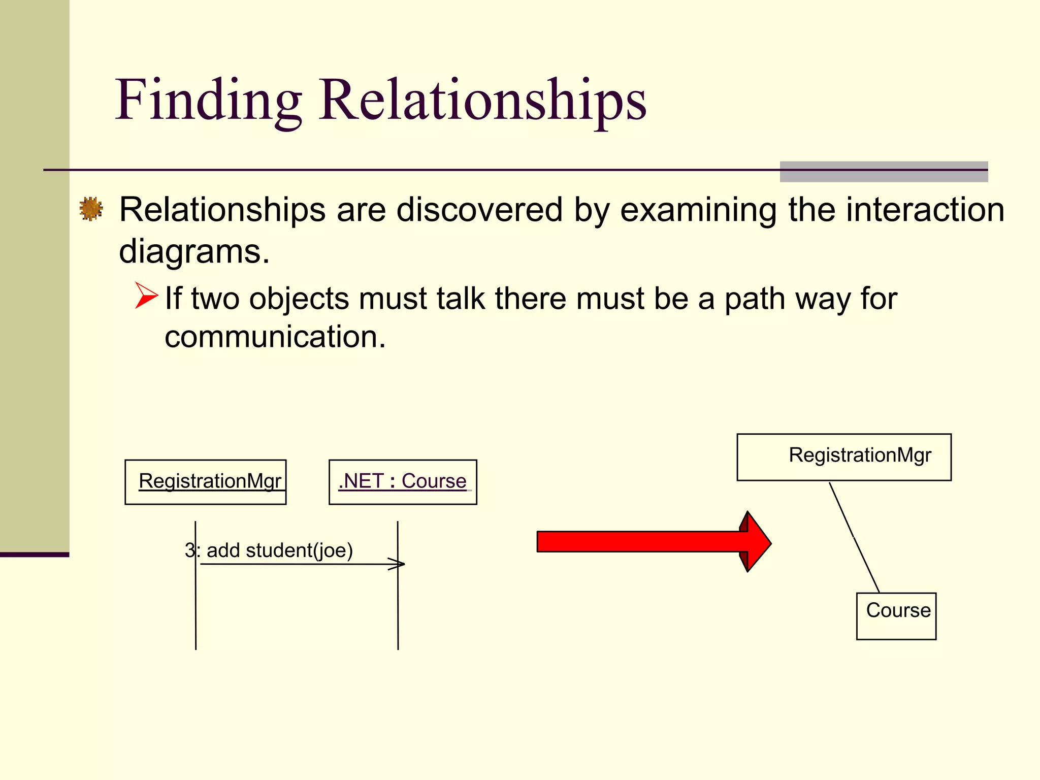
Discusses methods to discover relationships between objects through interaction diagrams.
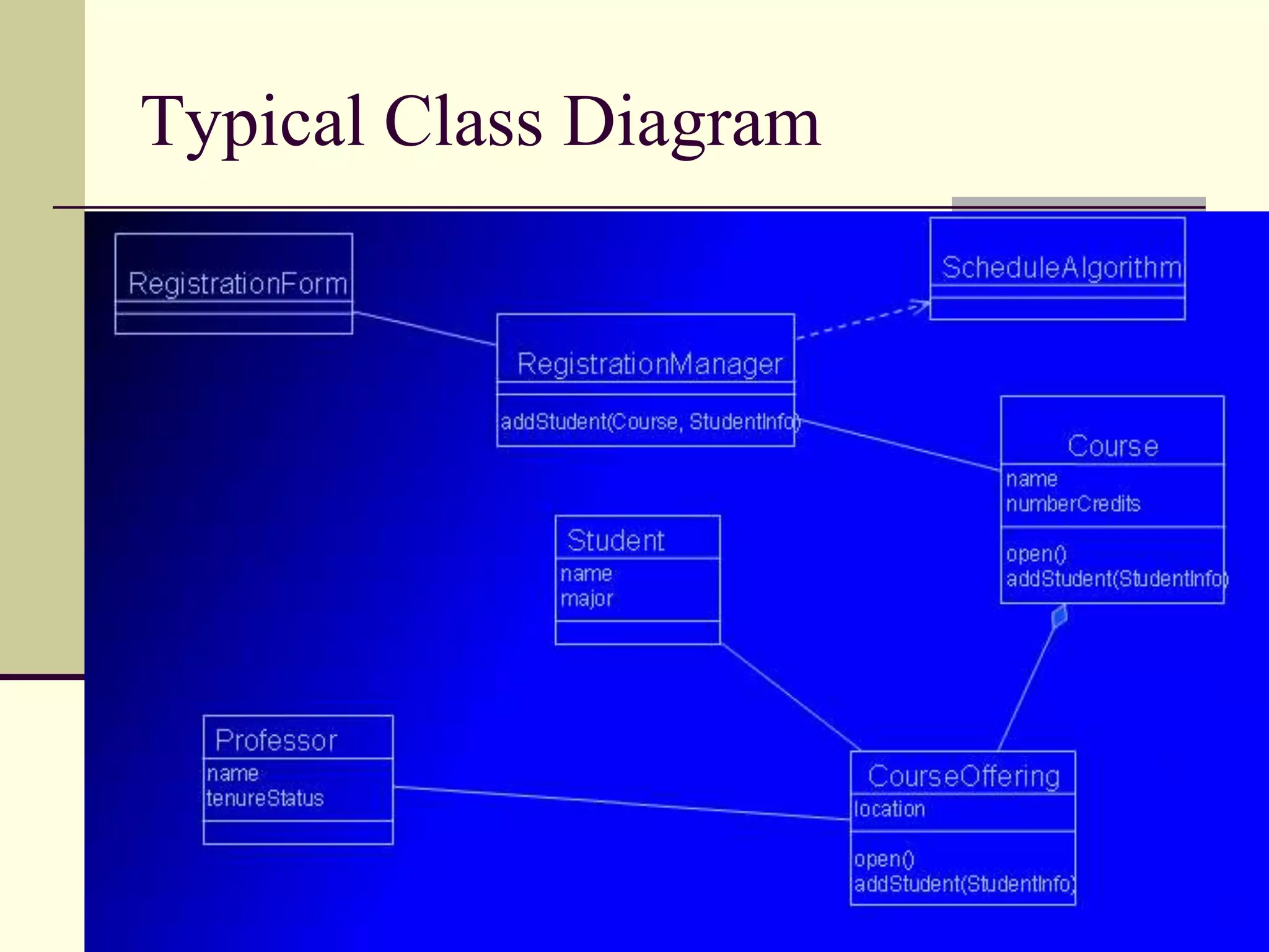
Provides a general view of a typical class diagram in UML.
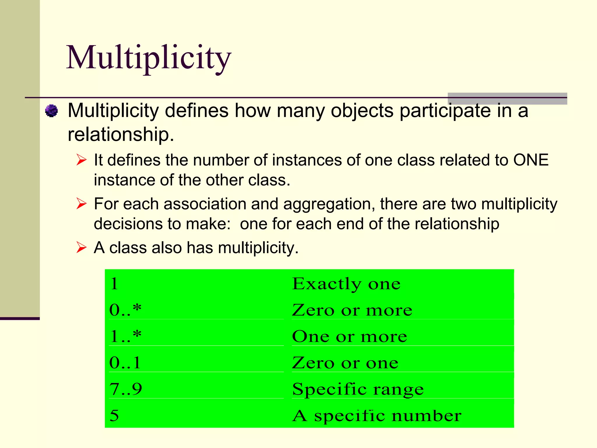
Defines multiplicity in UML, detailing the number of instances in relationships.
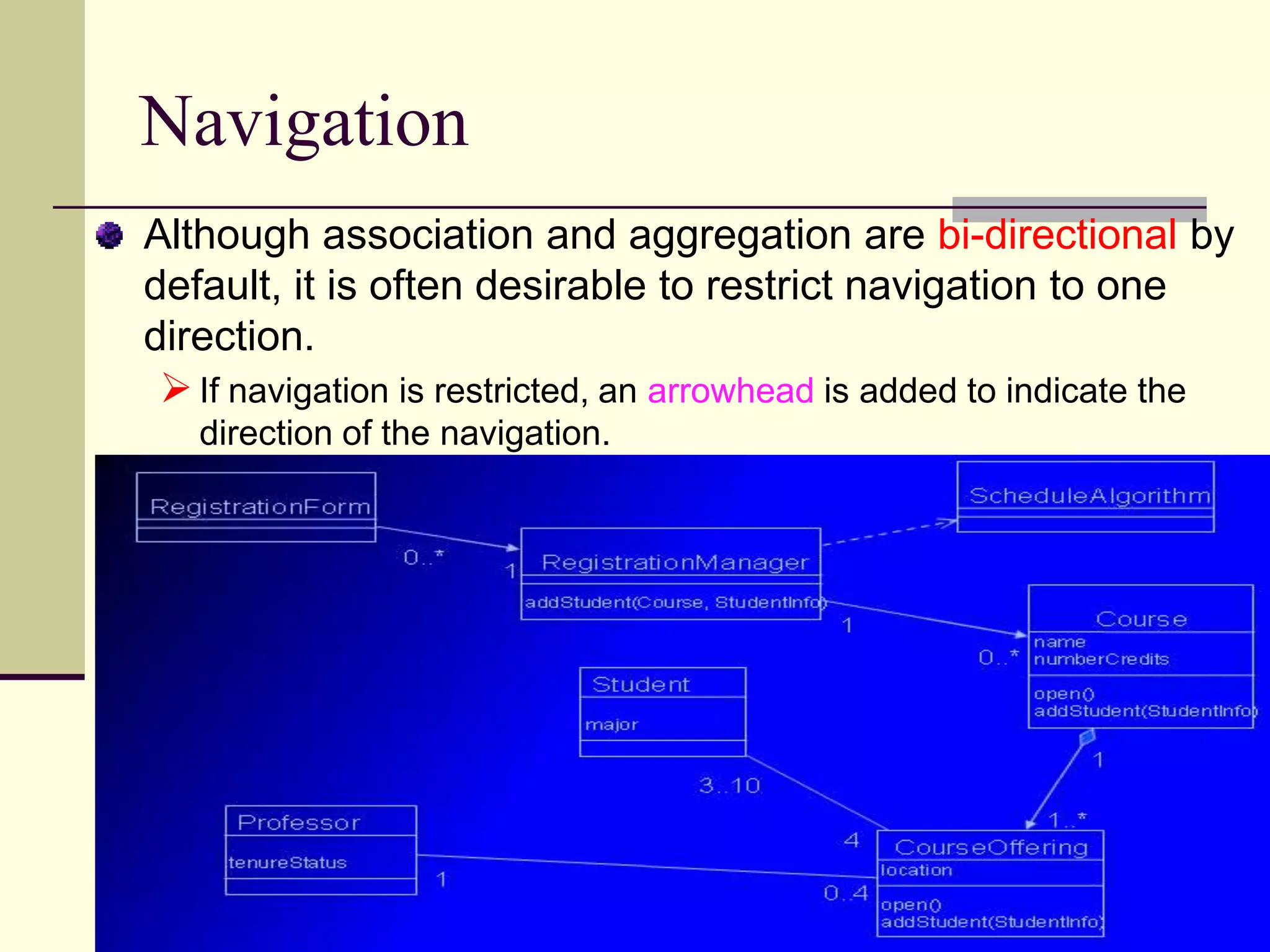
Explains navigation direction in associations and its representation in UML.
Discusses concurrency attributes in class diagrams addressing synchronization in multi-threaded environments.
Describes inheritance relationships in UML, including generalization and specialization concepts.
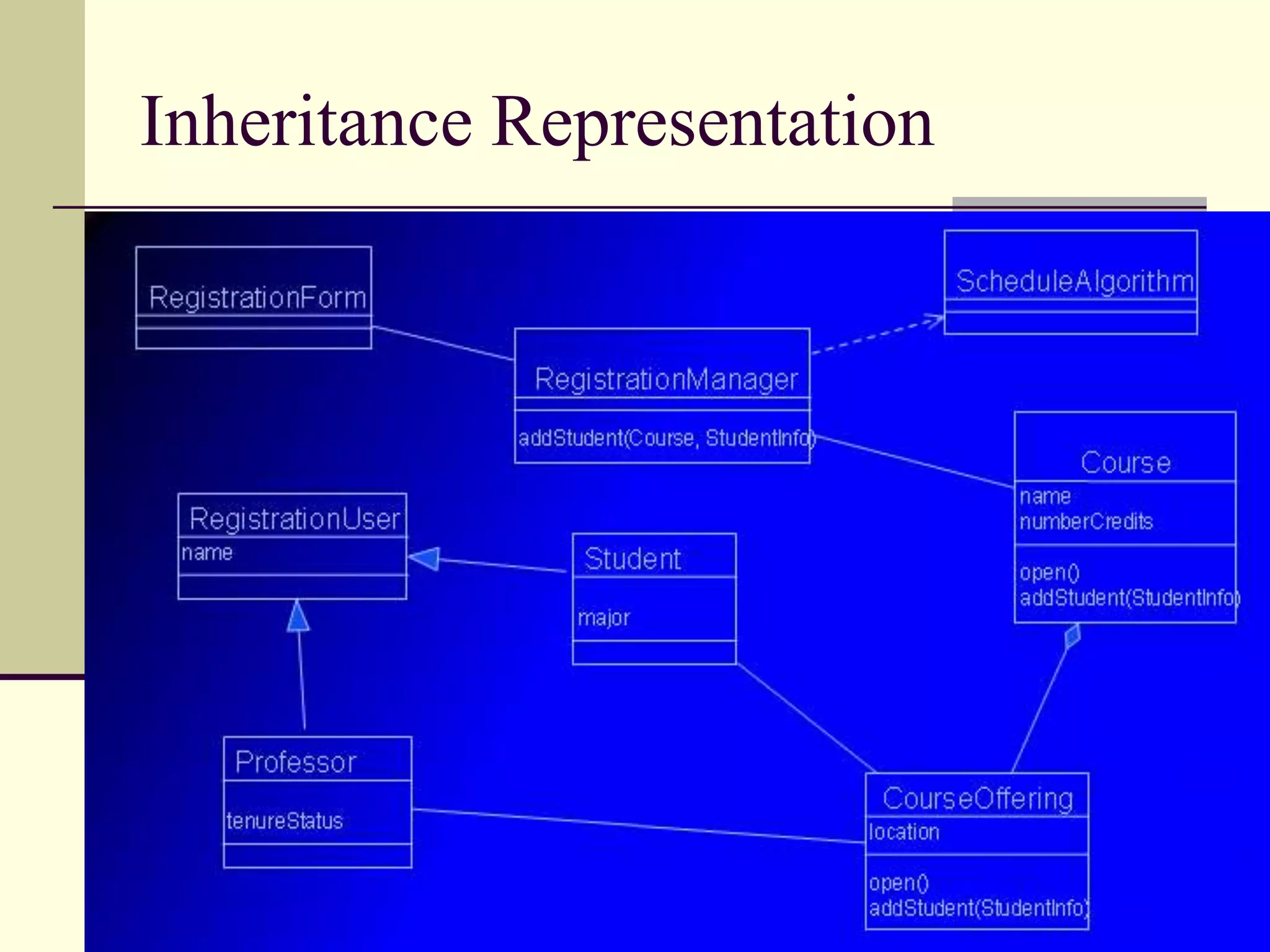
Explains how inheritance is represented in UML class diagrams.
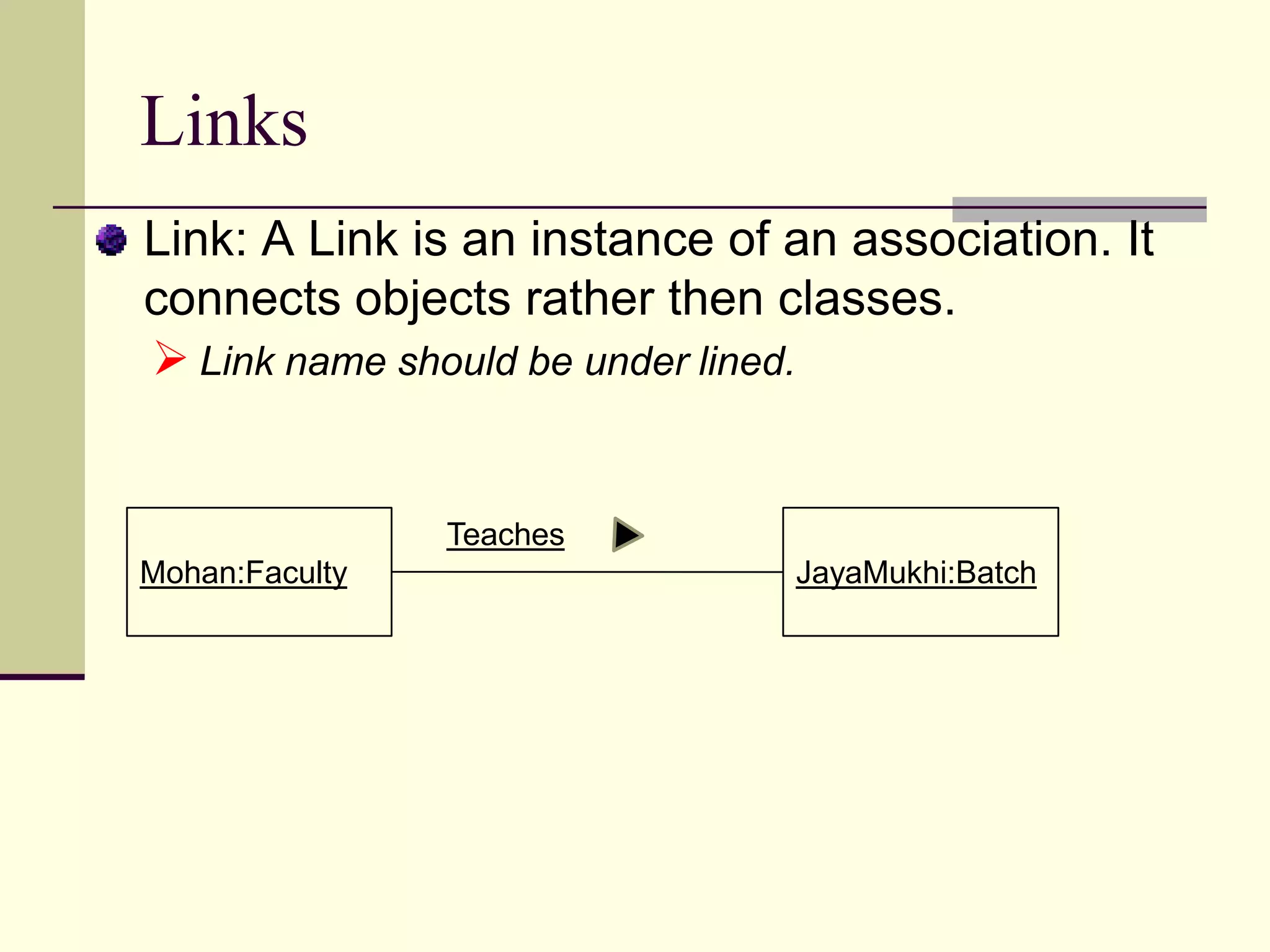
Defines links as instances of associations connecting objects.
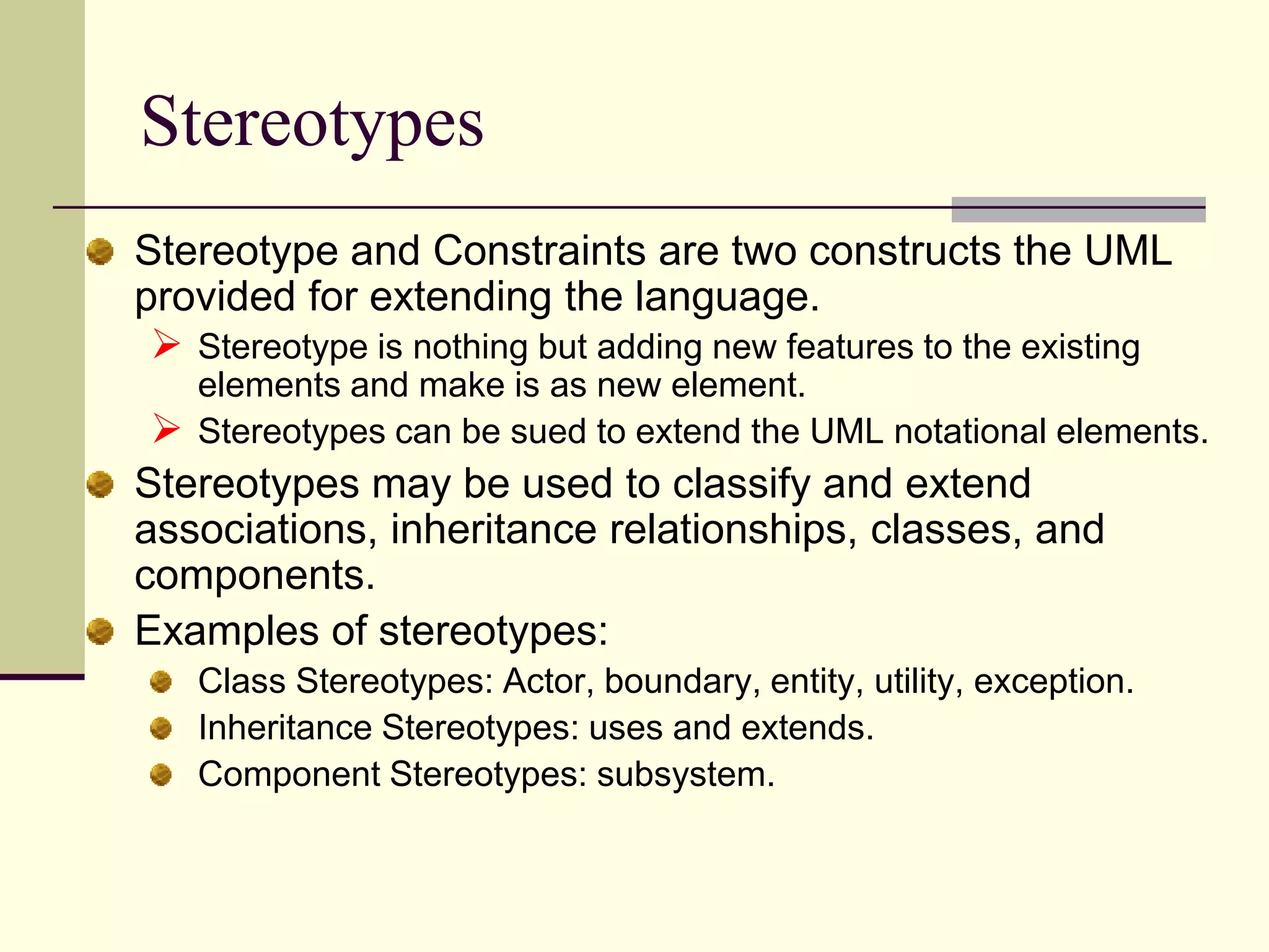
Explains stereotypes as a means to extend UML features and their usage.
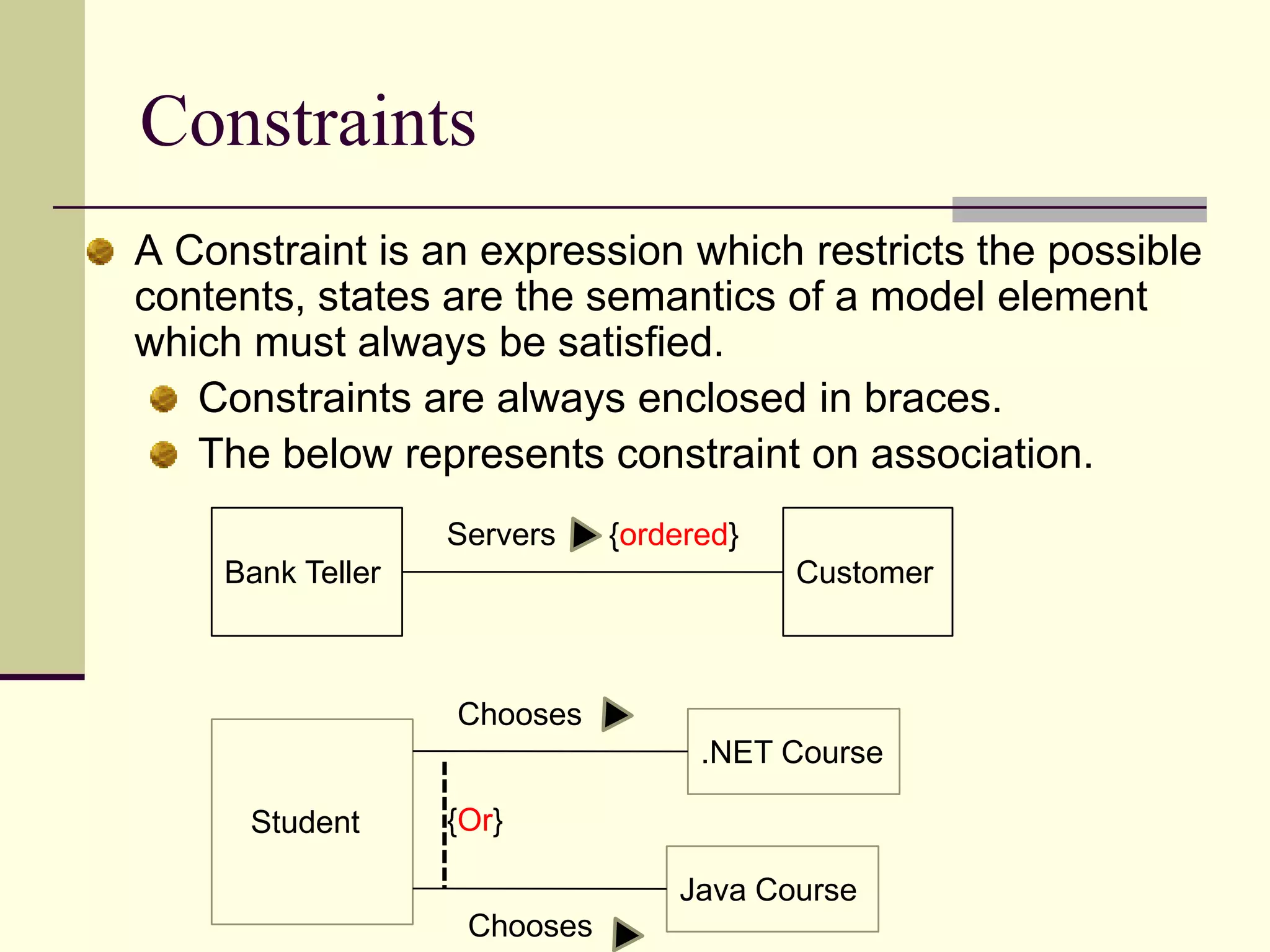
Defines constraints in UML modeling to enforce rules within a model.
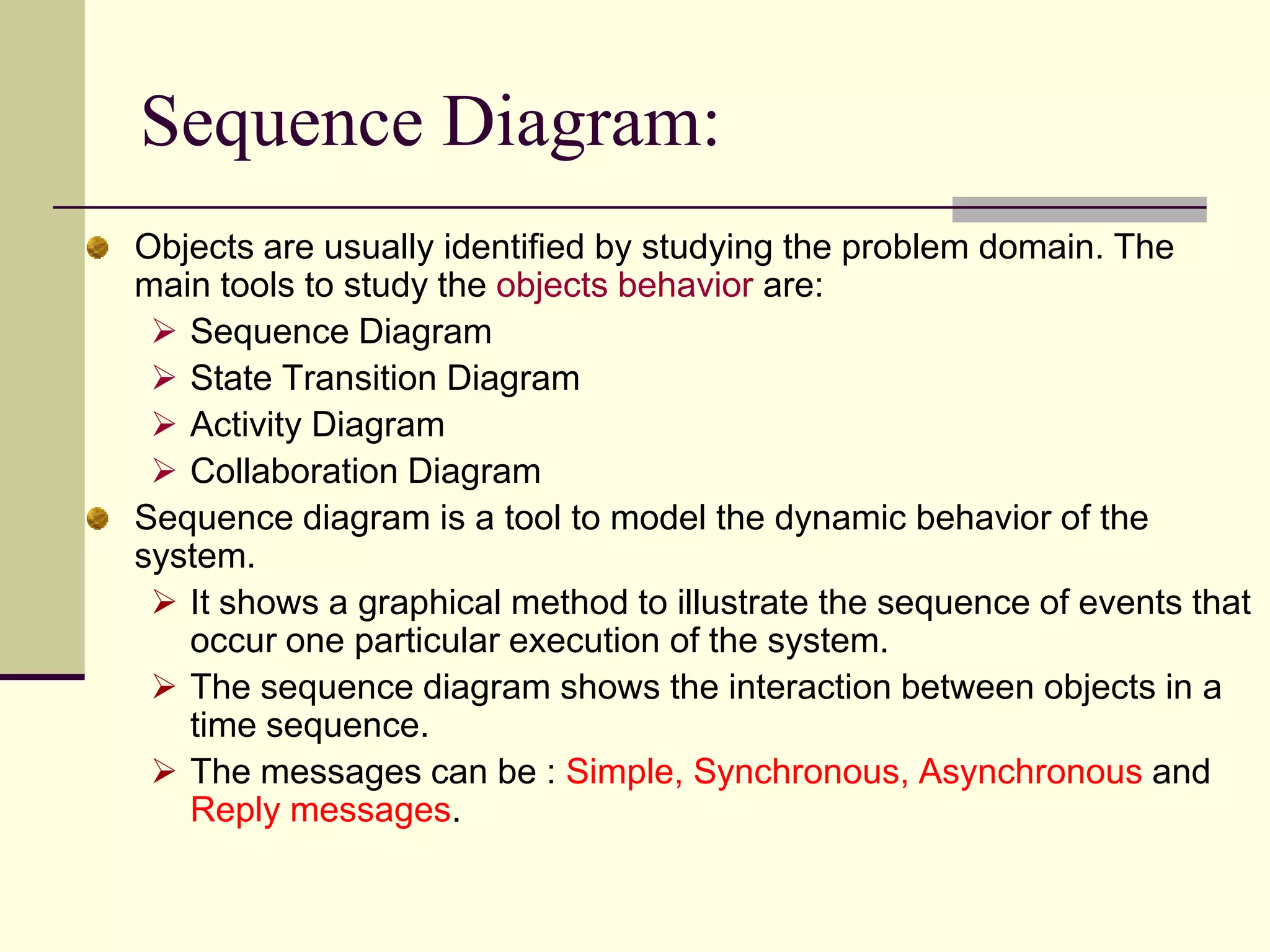
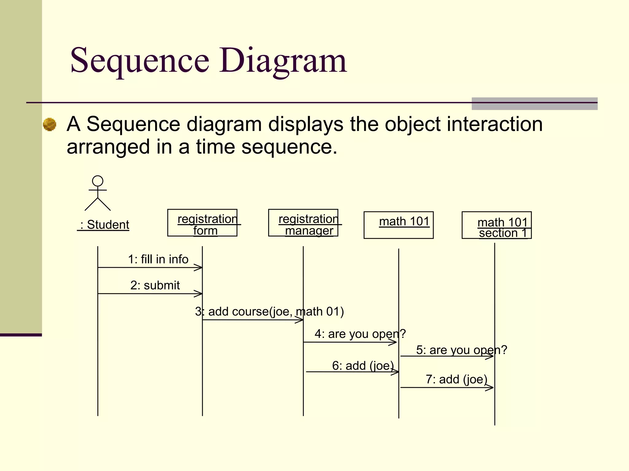
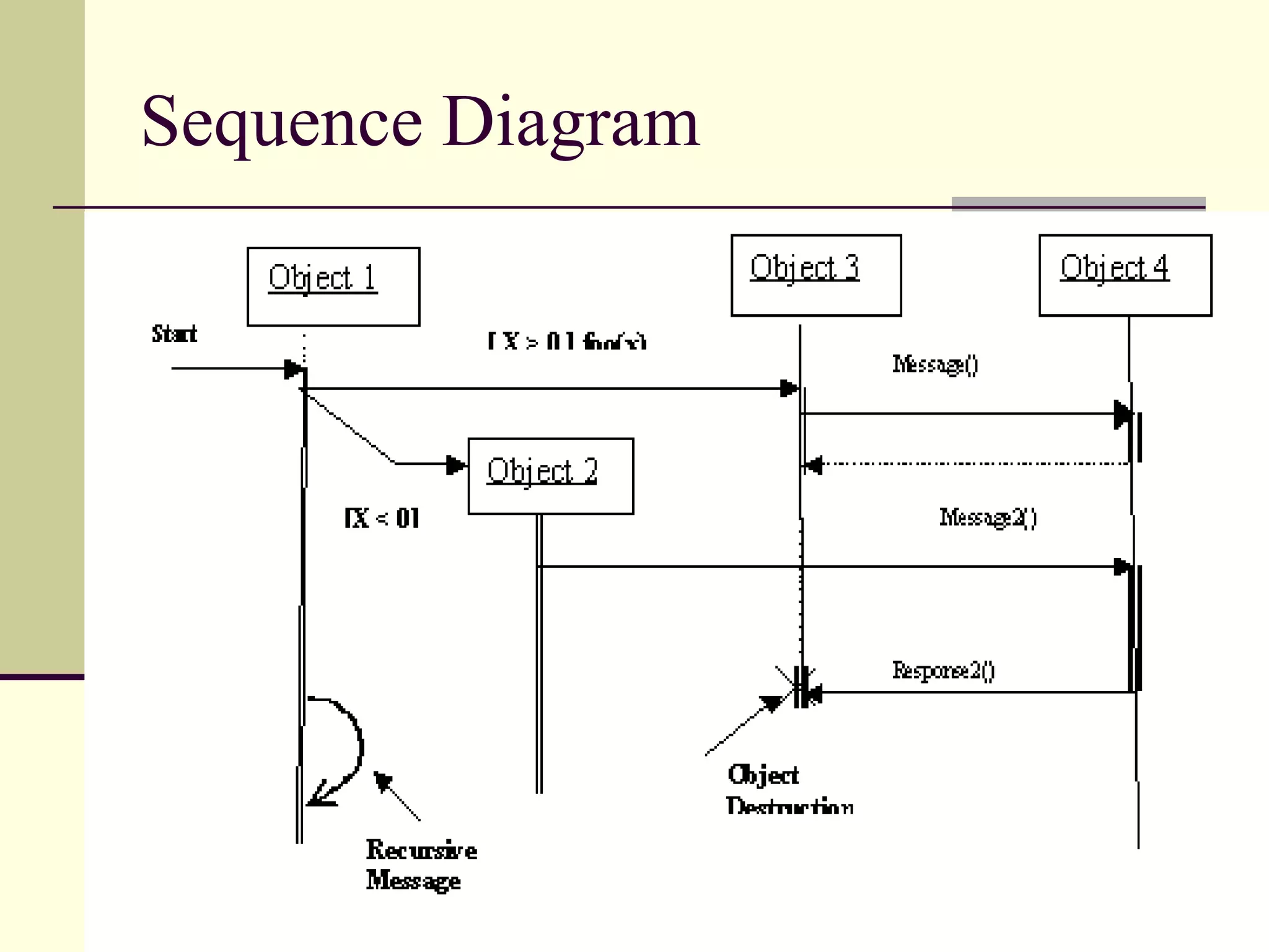
Explains sequence diagrams as a method to depict dynamic interactions in software.
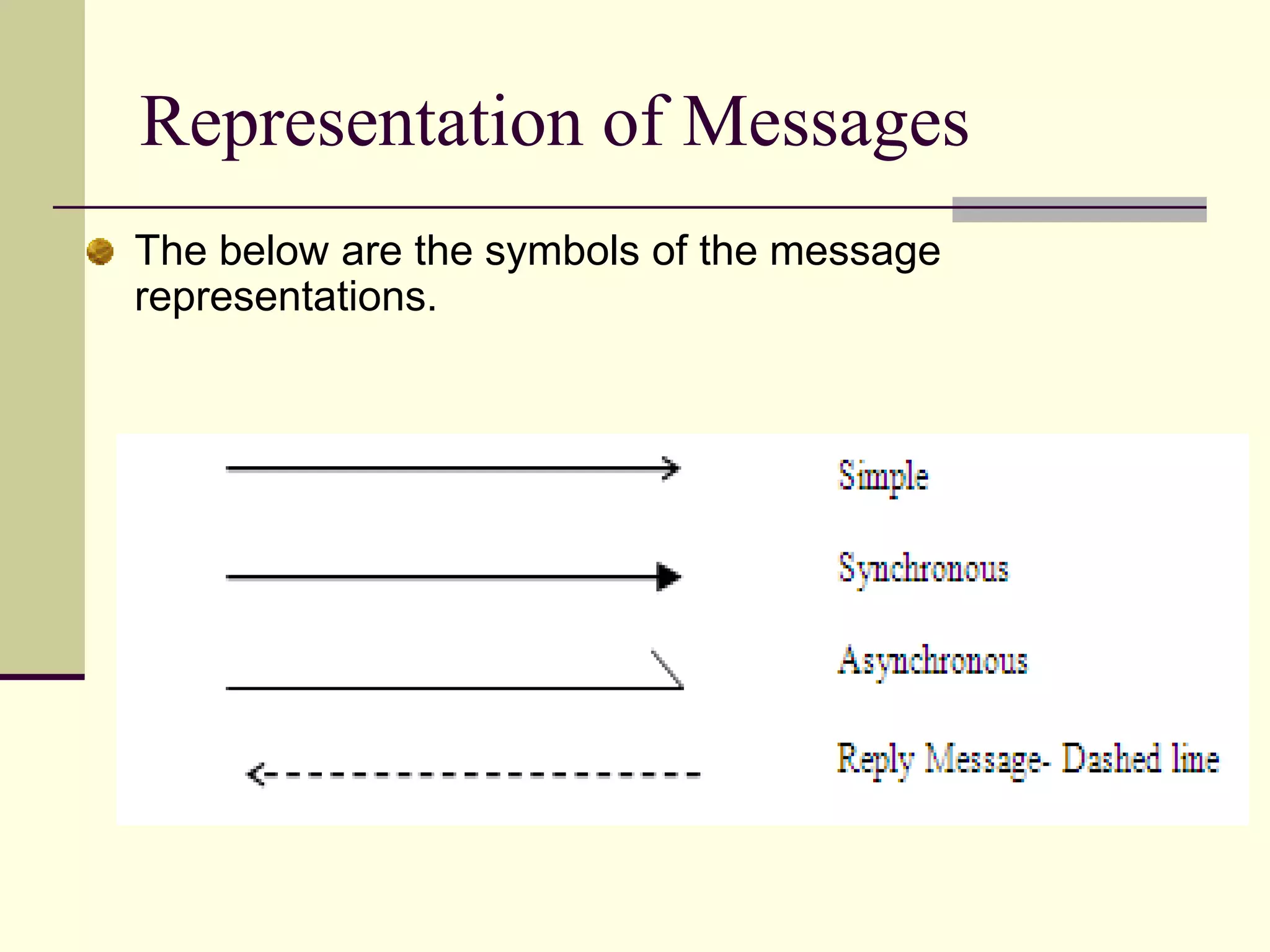
Shows symbols for different message representations in sequence diagrams.
Provides an example sequence diagram illustrating object interaction in time order.
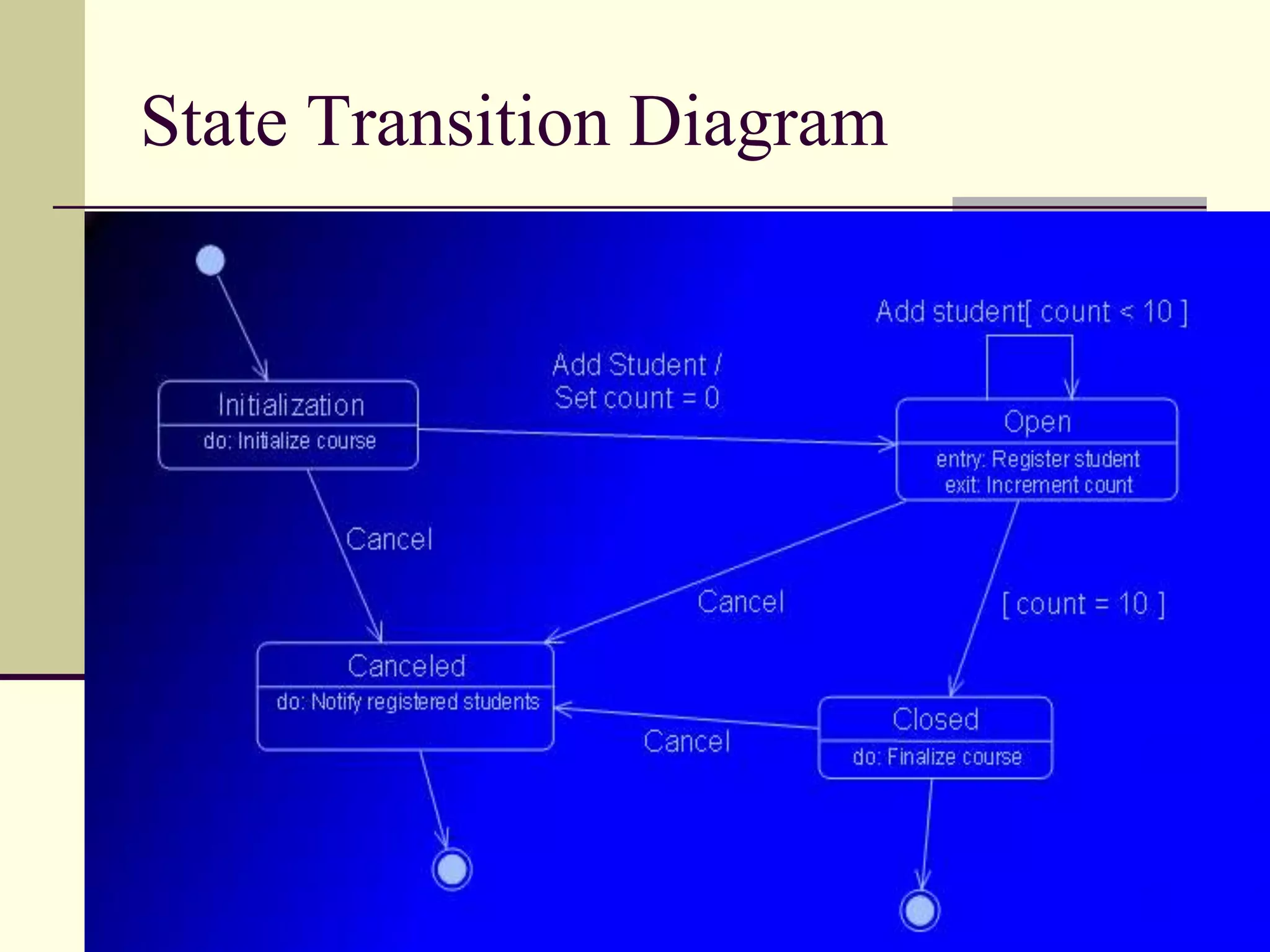
Describes state transition diagrams depicting the lifecycle of classes.
Example representation of state transition diagrams.
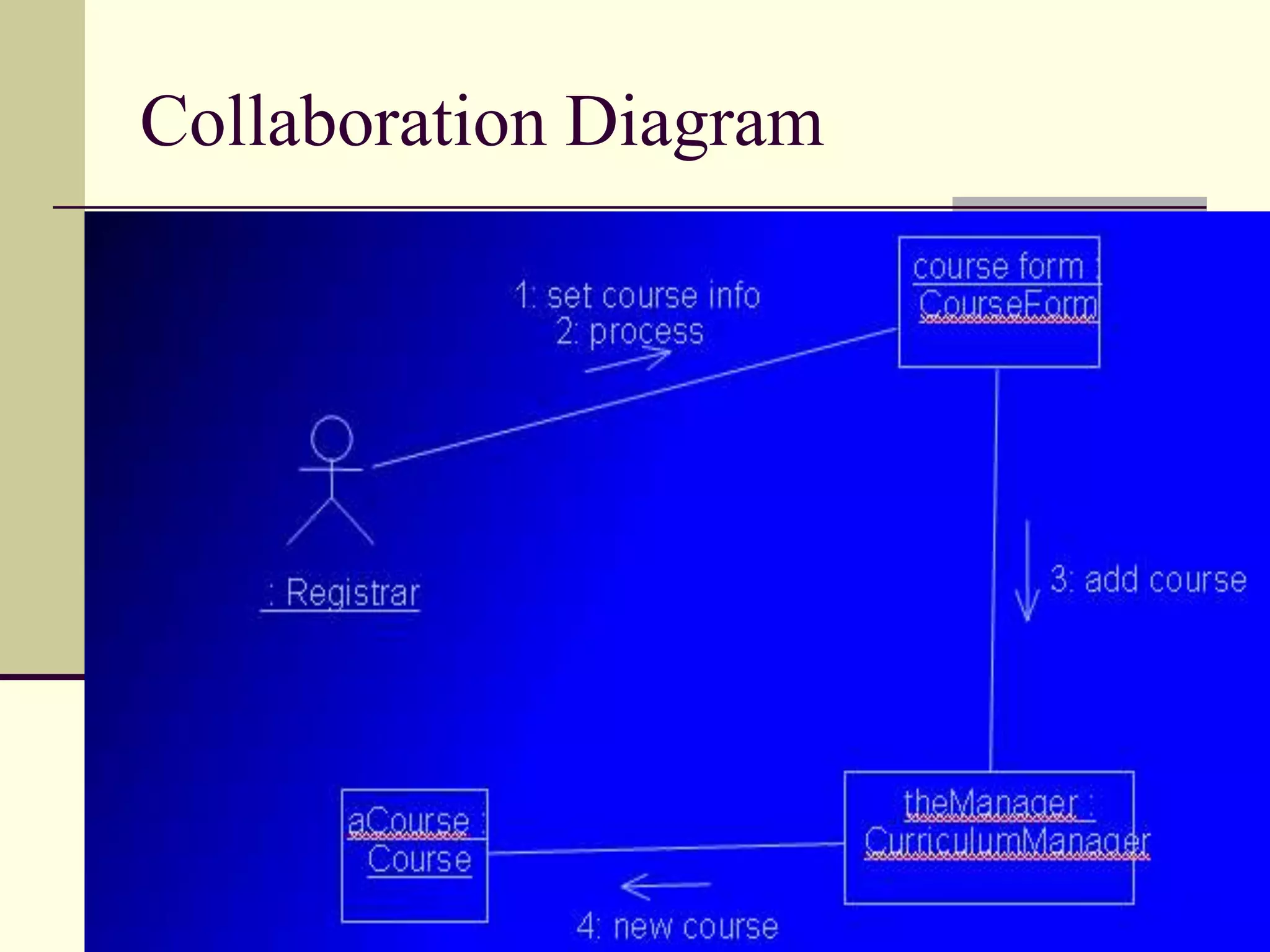
Explains collaboration diagrams focusing on interactions between objects.
Example representation of a collaboration diagram.
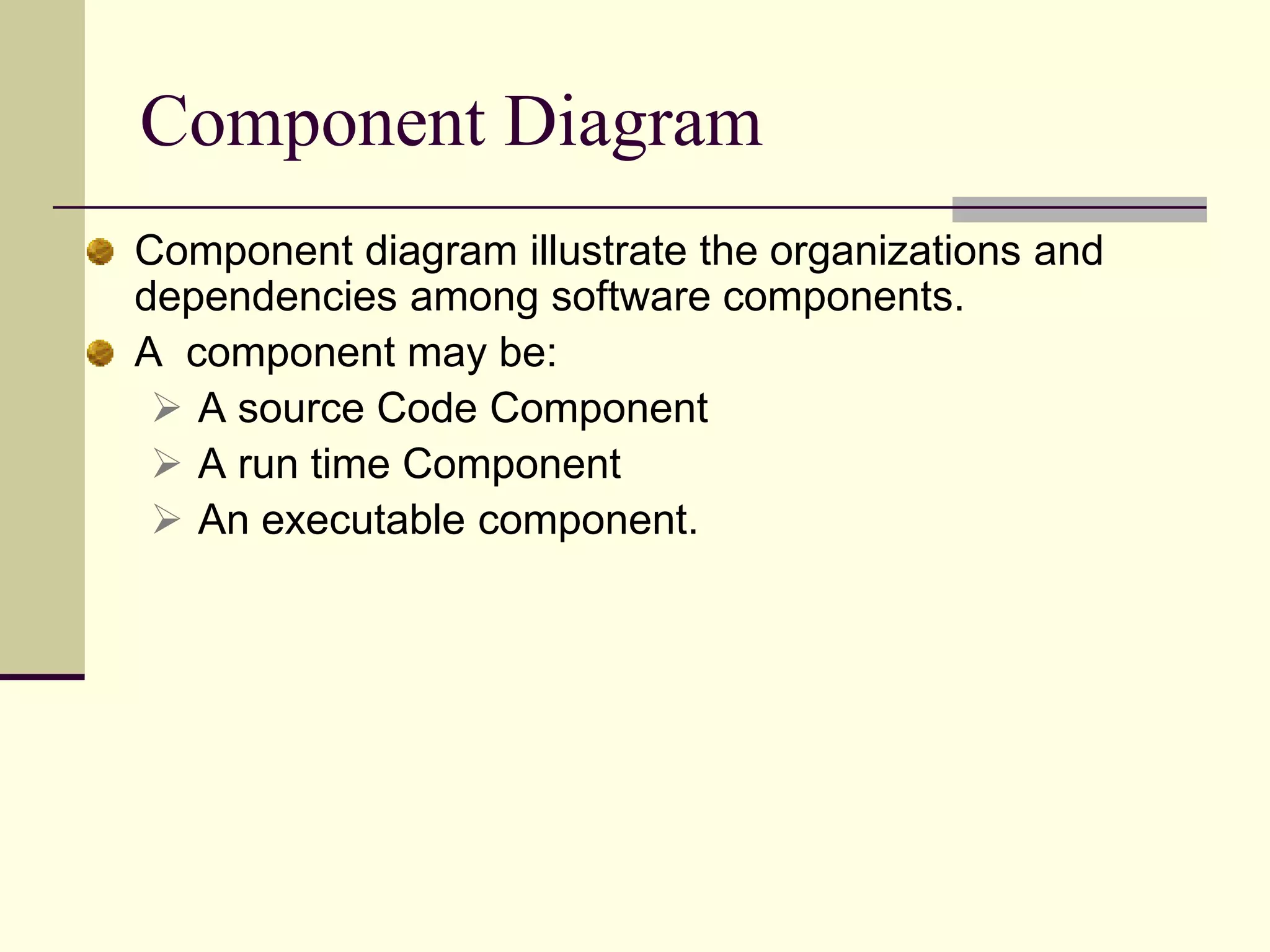
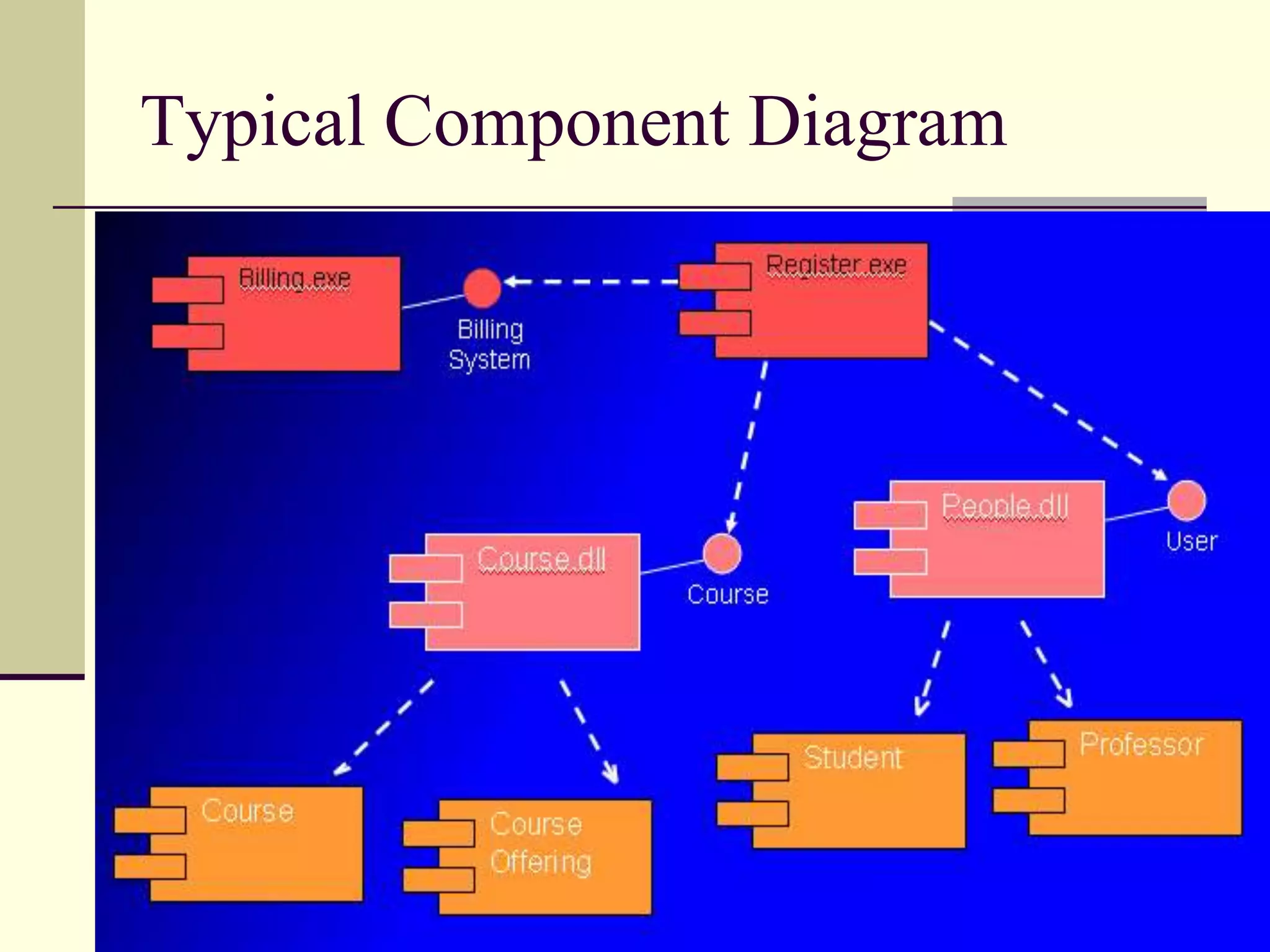
Illustrates component diagrams depicting organizations and dependencies among software components.
Visual representation of a typical component diagram in UML.
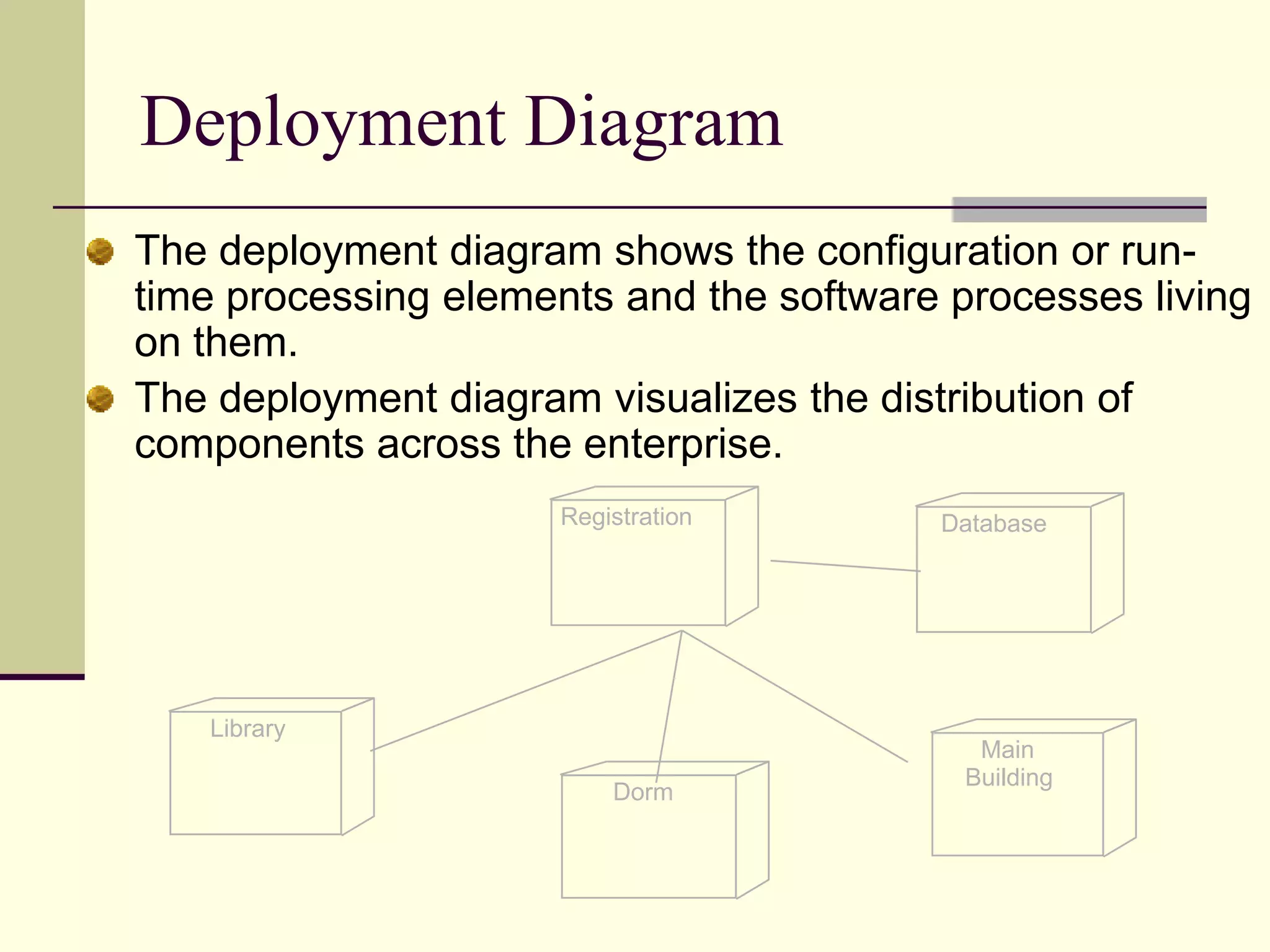
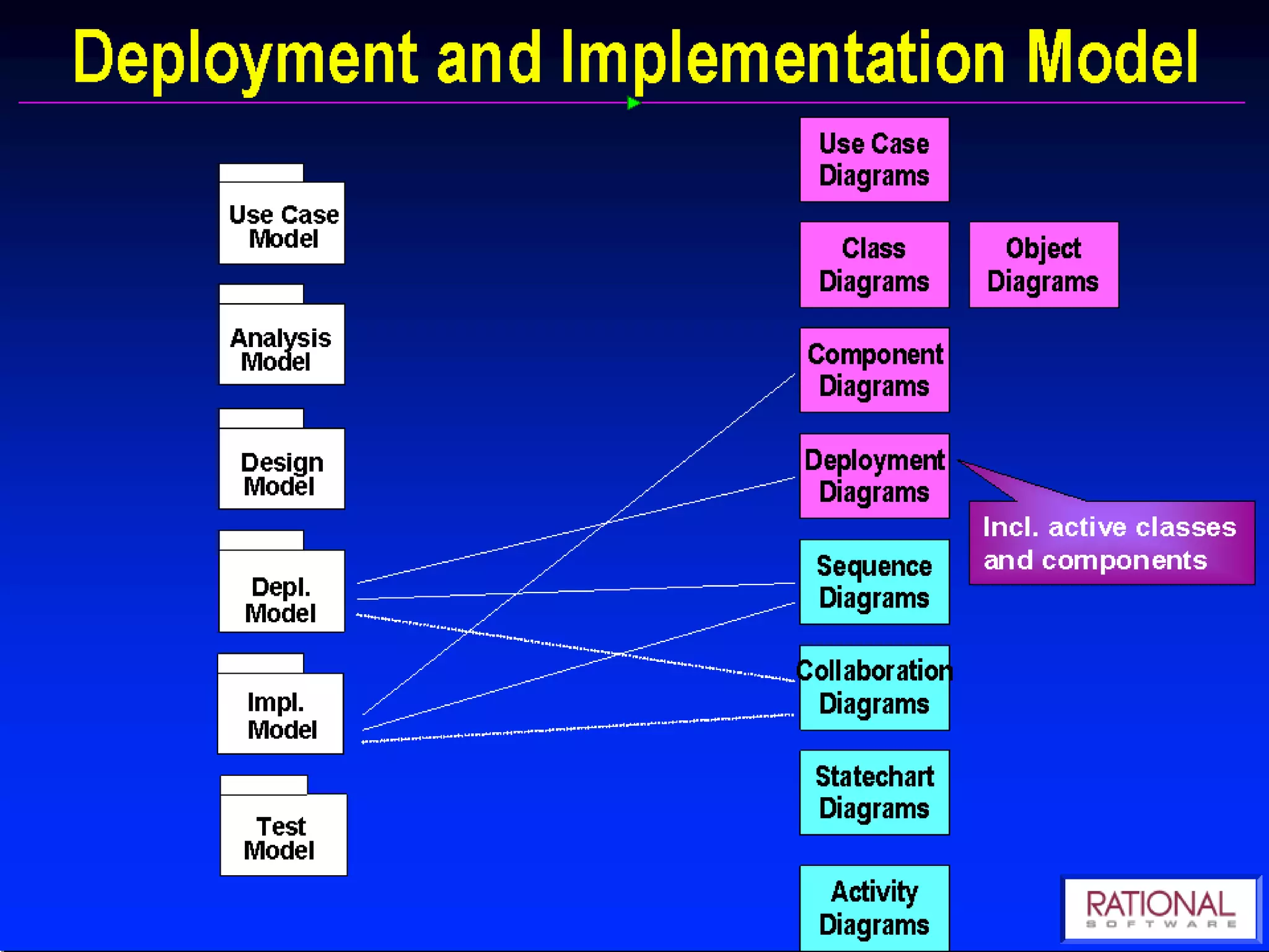
Describes deployment diagrams showing the distribution of software components across systems.
Open floor for questions regarding the discussed topics in the presentation.