Downloaded 237 times


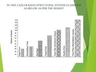
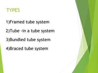
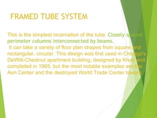

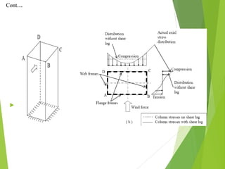

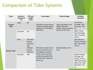
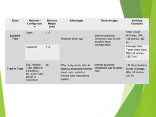


The document outlines the tube structure system, introduced by Fazlur Rahman Khan, which allows buildings to resist lateral loads by acting like hollow tubes. It covers the history, types (including framed tube, tube-in-tube, bundled tube, and braced tube systems), and advantages of these structures, which have become common in skyscraper designs since the 1960s. The document also highlights the influence of tube structures on significant skyscrapers, underscoring their efficiency in providing usable space while resisting various forces.


