Download as PDF, PPTX
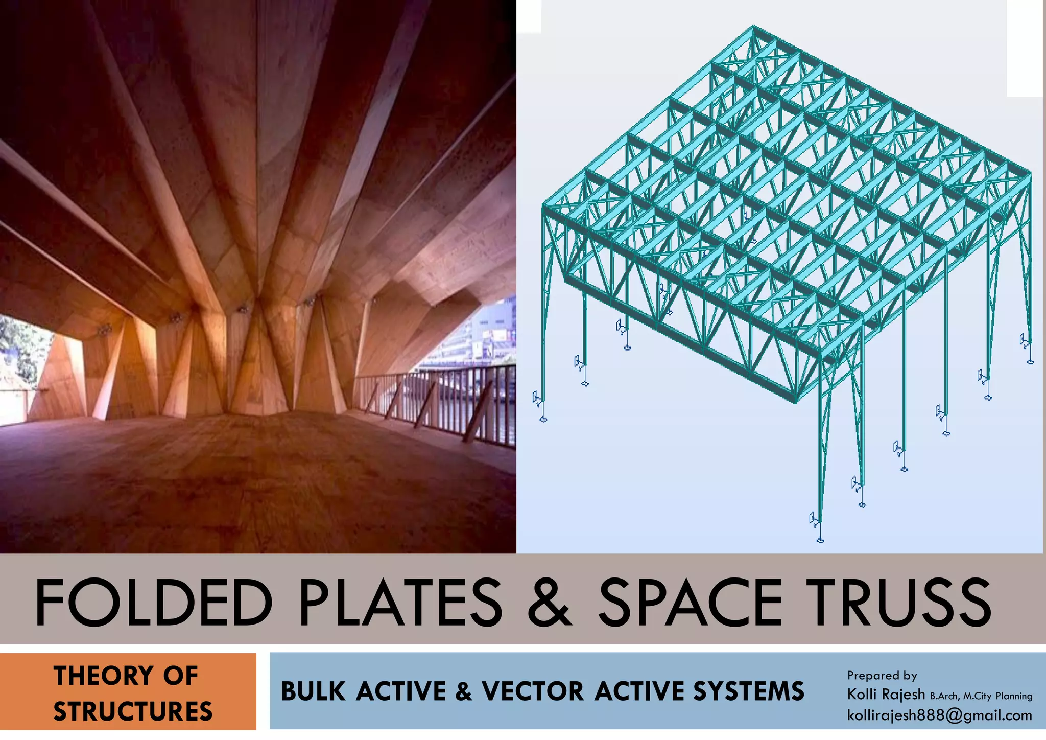
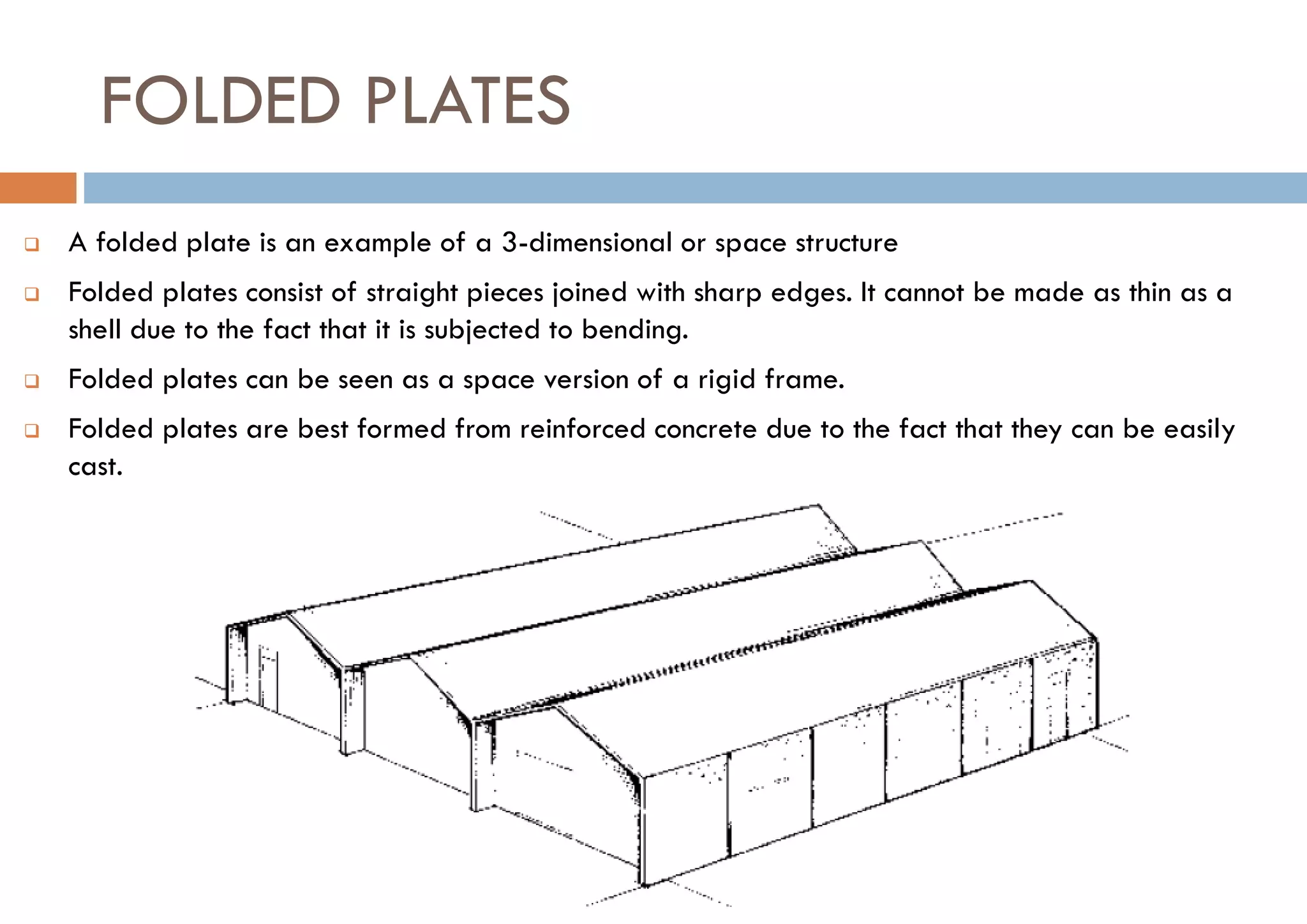
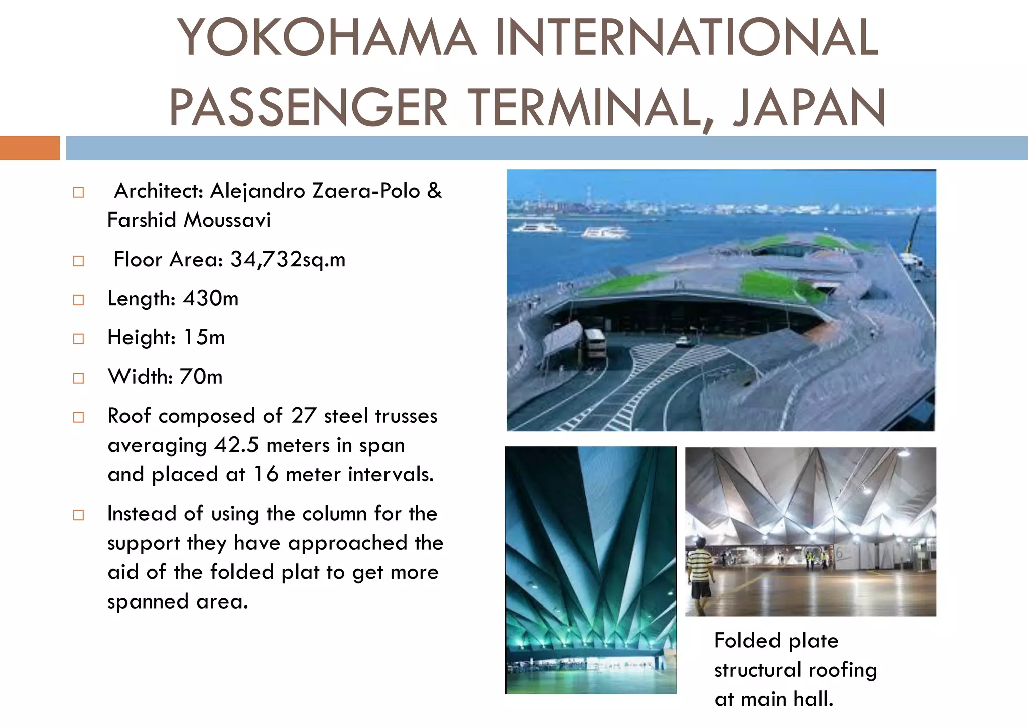
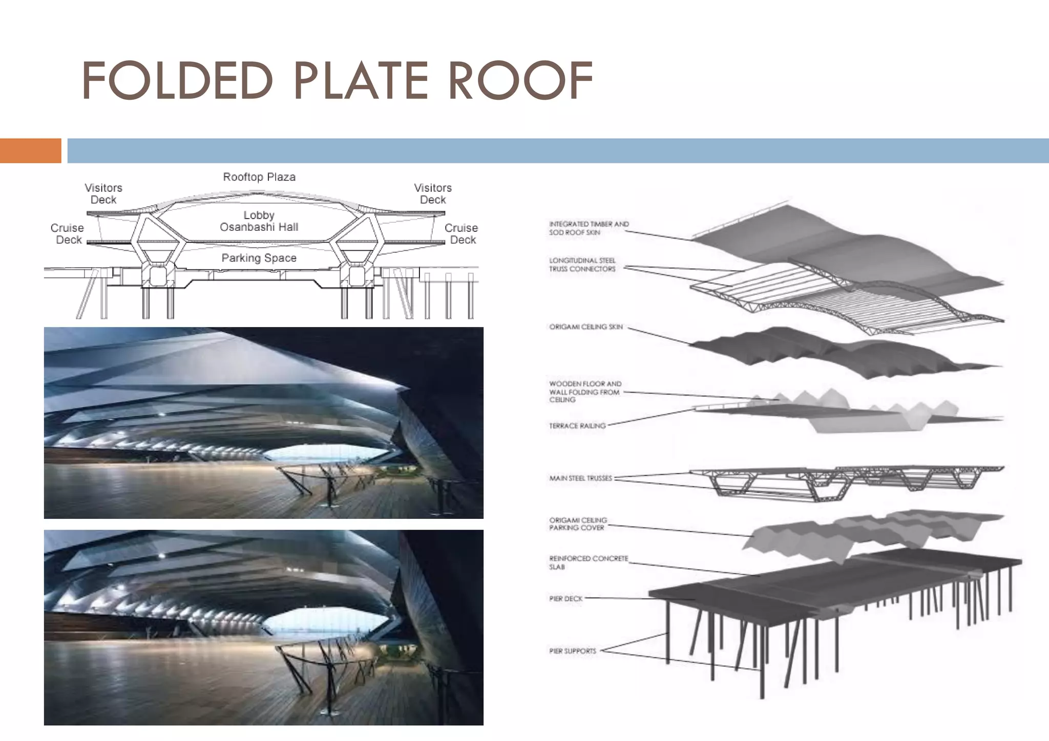
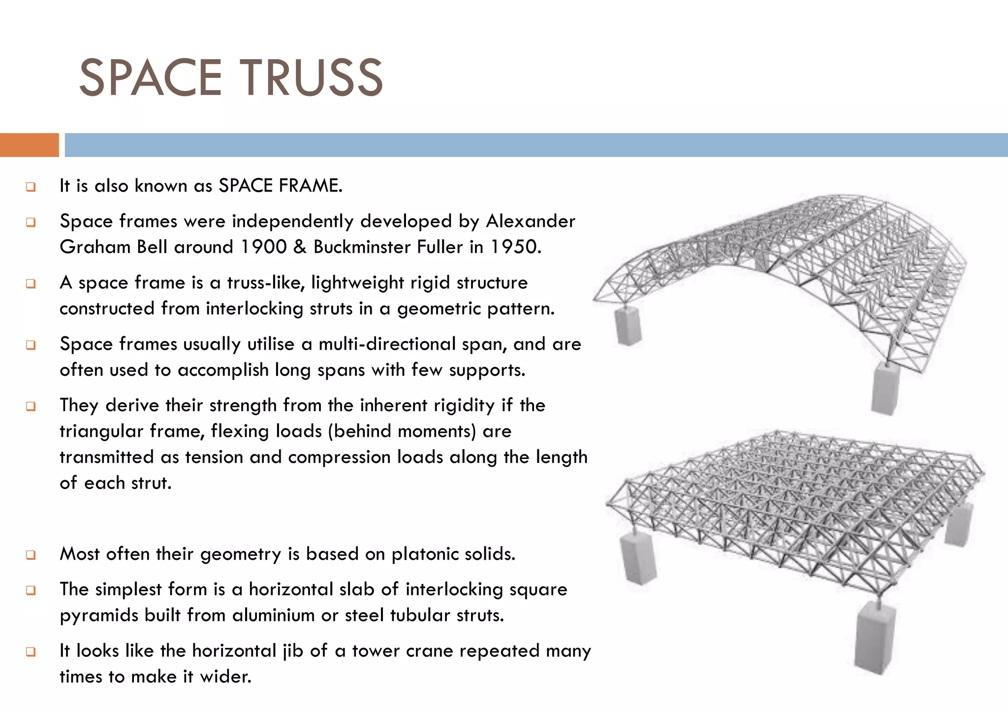
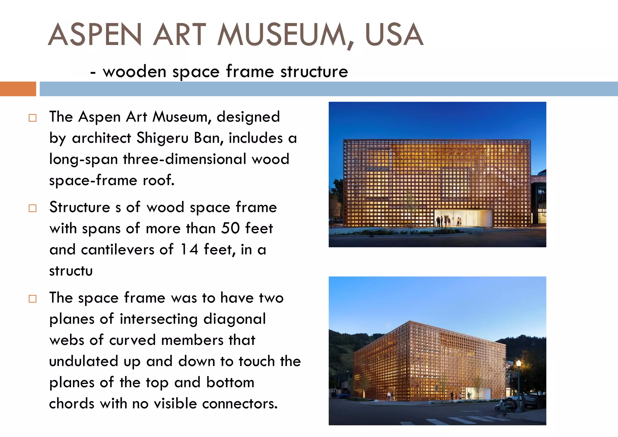
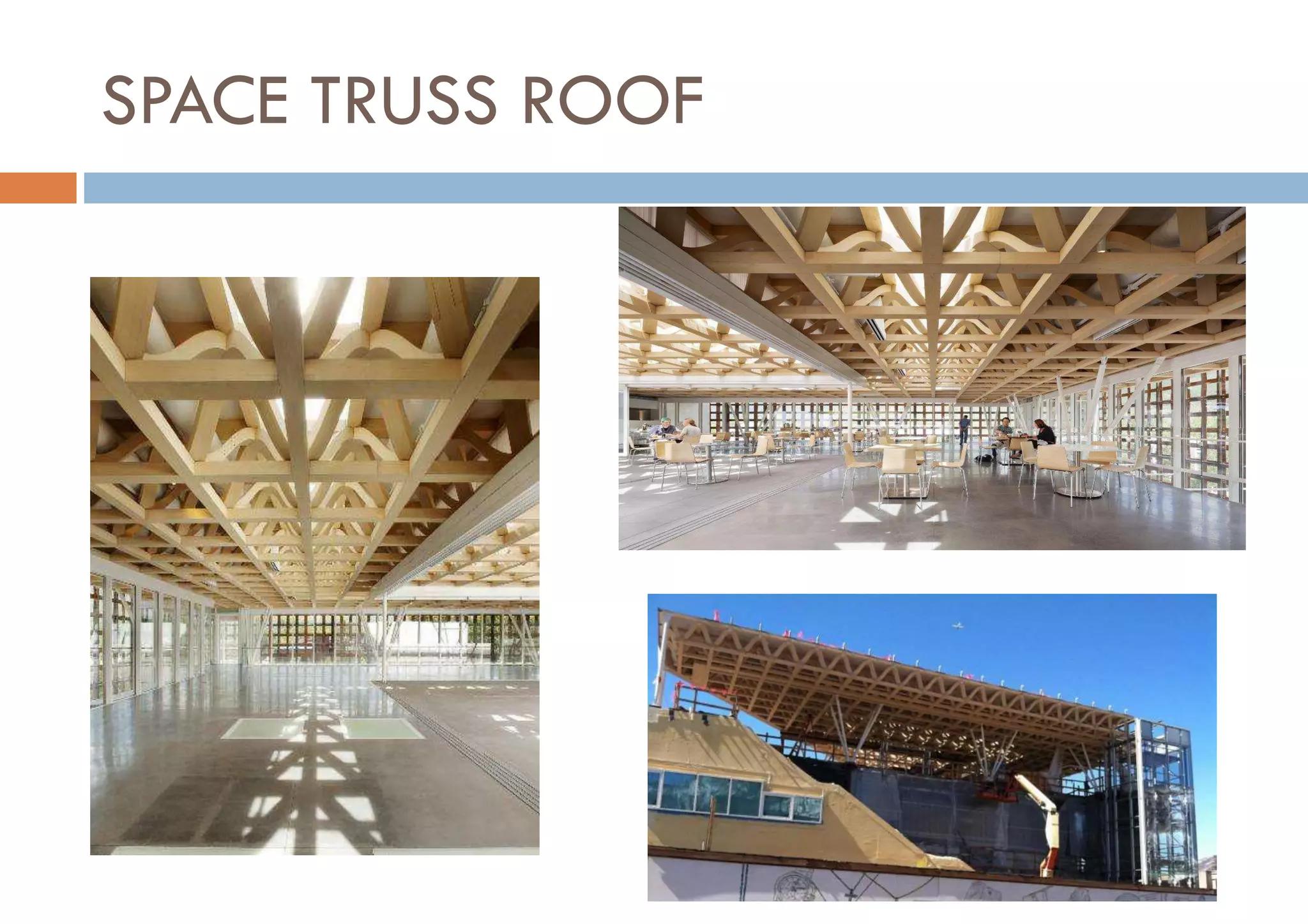

The document discusses folded plates and space trusses. It defines folded plates as 3D structures made of straight pieces joined at sharp edges, and notes they are best constructed from reinforced concrete. Space trusses, also called space frames, are lightweight rigid structures made of interlocking struts in a geometric pattern that derive strength from triangular frames transmitting loads as tension and compression. Examples given are the Yokohama passenger terminal roof's folded plates and the Aspen Art Museum's long-span wood space frame roof.


