Downloaded 78 times
![3GPP TS 36.331 version 10.2.0 Release 10 14 ETSI TS 136 331 V10.2.0 (2011-07)
1 Scope
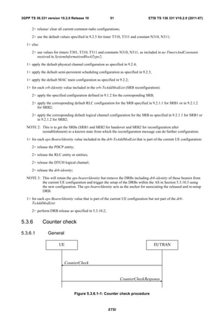
The present document specifies the Radio Resource Control protocol for the radio interface between UE and E-UTRAN
as well as for the radio interface between RN and E-UTRAN.
The scope of the present document also includes:
- the radio related information transported in a transparent container between source eNB and target eNB upon
inter eNB handover;
- the radio related information transported in a transparent container between a source or target eNB and another
system upon inter RAT handover.
2 References
The following documents contain provisions which, through reference in this text, constitute provisions of the present
document.
• References are either specific (identified by date of publication, edition number, version number, etc.) or
non-specific.
• For a specific reference, subsequent revisions do not apply.
• For a non-specific reference, the latest version applies. In the case of a reference to a 3GPP document (including
a GSM document), a non-specific reference implicitly refers to the latest version of that document in the same
Release as the present document.
[1] 3GPP TR 21.905: "Vocabulary for 3GPP Specifications".
[2] Void.
[3] 3GPP TS 36.302: "Evolved Universal Terrestrial Radio Access (E-UTRA); Services provided by
the physical layer ".
[4] 3GPP TS 36.304: "Evolved Universal Terrestrial Radio Access (E-UTRA); UE Procedures in Idle
Mode".
[5] 3GPP TS 36.306 "Evolved Universal Terrestrial Radio Access (E-UTRA); UE Radio Access
Capabilities".
[6] 3GPP TS 36.321: "Evolved Universal Terrestrial Radio Access (E-UTRA); Medium Access
Control (MAC) protocol specification".
[7] 3GPP TS 36.322:"Evolved Universal Terrestrial Radio Access (E-UTRA); Radio Link Control
(RLC) protocol specification".
[8] 3GPP TS 36.323: "Evolved Universal Terrestrial Radio Access (E-UTRA); Packet Data
Convergence Protocol (PDCP) Specification".
[9] 3GPP TS 36.300: "Evolved Universal Terrestrial Radio Access (E-UTRA) and Evolved Universal
Terrestrial Radio Access (E-UTRAN); Overall description; Stage 2".
[10] 3GPP TS 22.011: "Service accessibility".
[11] 3GPP TS 23.122: "Non-Access-Stratum (NAS) functions related to Mobile Station (MS) in idle
mode".
[12] 3GPP2 C.S0002-A v6.0: "Physical Layer Standard for cdma2000 Spread Spectrum Systems –
Release A".
ETSI](https://image.slidesharecdn.com/ts136331v100200p-111014005410-phpapp02/85/Ts-136331v100200p-15-320.jpg)
![3GPP TS 36.331 version 10.2.0 Release 10 15 ETSI TS 136 331 V10.2.0 (2011-07)
[13] ITU-T Recommendation X.680 (07/2002) "Information Technology - Abstract Syntax Notation
One (ASN.1): Specification of basic notation" (Same as the ISO/IEC International Standard 8824-
1).
[14] ITU-T Recommendation X.681 (07/2002) "Information Technology - Abstract Syntax Notation
One (ASN.1): Information object specification" (Same as the ISO/IEC International Standard
8824-2).
[15] ITU-T Recommendation X.691 (07/2002) "Information technology - ASN.1 encoding rules:
Specification of Packed Encoding Rules (PER)" (Same as the ISO/IEC International Standard
8825-2).
[16] 3GPP TS 36.133: "Evolved Universal Terrestrial Radio Access (E-UTRA); Requirements for
support of radio resource management".
[17] 3GPP TS 25.101: "Universal Terrestrial Radio Access (UTRA); User Equipment (UE) radio
transmission and reception (FDD)".
[18] 3GPP TS 25.102: "Universal Terrestrial Radio Access (UTRA); User Equipment (UE) radio
transmission and reception (TDD)".
[19] 3GPP TS 25.331:"Universal Terrestrial Radio Access (UTRA); Radio Resource Control (RRC);
Protocol specification".
[20] 3GPP TS 45.005: "Radio transmission and reception".
[21] 3GPP TS 36.211: "Evolved Universal Terrestrial Radio Access (E-UTRA); Physical Channels and
Modulation".
[22] 3GPP TS 36.212: "Evolved Universal Terrestrial Radio Access (E-UTRA); Multiplexing and
channel coding".
[23] 3GPP TS 36.213: "Evolved Universal Terrestrial Radio Access (E-UTRA); Physical layer
procedures".
[24] 3GPP2 C.S0057-B v1.0: "Band Class Specification for cdma2000 Spread Spectrum Systems".
[25] 3GPP2 C.S0005-A v6.0: "Upper Layer (Layer 3) Signaling Standard for cdma2000 Spread
Spectrum Systems – Release A, Addendum 2".
[26] 3GPP2 C.S0024-A v3.0: "cdma2000 High Rate Packet Data Air Interface Specification".
[27] 3GPP TS 23.003: "Numbering, addressing and identification".
[28] 3GPP TS 45.008: "Radio subsystem link control".
[29] 3GPP TS 25.133: "Requirements for Support of Radio Resource Management (FDD)".
[30] 3GPP TS 25.123: "Requirements for Support of Radio Resource Management (TDD)".
[31] 3GPP TS 36.401: "Evolved Universal Terrestrial Radio Access (E-UTRA); Architecture
description".
[32] 3GPP TS 33.401: "3GPP System Architecture Evolution (SAE); Security architecture".
[33] 3GPP2 A.S0008-C v2.0: "Interoperability Specification (IOS) for High Rate Packet Data (HRPD)
Radio Access Network Interfaces with Session Control in the Access Network"
[34] 3GPP2 C.S0004-A v6.0: "Signaling Link Access Control (LAC) Standard for cdma2000 Spread
Spectrum Systems – Addendum 2"
[35] 3GPP TS 24.301: "Non-Access-Stratum (NAS) protocol for Evolved Packet System (EPS); Stage
3".
[36] 3GPP TS 44.060: "General Packet Radio Service (GPRS); Mobile Station (MS) - Base Station
System (BSS) interface; Radio Link Control/Medium Access Control (RLC/MAC) protocol".
ETSI](https://image.slidesharecdn.com/ts136331v100200p-111014005410-phpapp02/85/Ts-136331v100200p-16-320.jpg)
![3GPP TS 36.331 version 10.2.0 Release 10 16 ETSI TS 136 331 V10.2.0 (2011-07)
[37] 3GPP TS 23.041: "Technical realization of Cell Broadcast Service (CBS)".
[38] 3GPP TS 23.038: "Alphabets and Language".
[39] 3GPP TS 36.413: "Evolved Universal Terrestrial Radio Access (E-UTRAN); S1 Application
Protocol (S1 AP)".
[40] 3GPP TS 25.304: "Universal Terrestrial Radio Access (UTRAN); User Equipment (UE)
procedures in idle mode and procedures for cell reselection in connected mode".
[41] 3GPP TS 23.401: "General Packet Radio Service (GPRS) enhancements for Evolved Universal
Terrestrial Radio Access Network (E-UTRAN) access".
[42] 3GPP TS 36.101: "Evolved Universal Terrestrial Radio Access (E-UTRA); User Equipment (UE)
radio transmission and reception".
[43] 3GPP TS 44.005: "Data Link (DL) Layer General Aspects".
[44] 3GPP2 C.P0087-A: "E-UTRAN - cdma2000 HRPD Connectivity and Interworking: Air Interface
Specification"
Editor's note: The above document cannot be formally referenced until it is published by 3GPP2, at which time it
will be designated as C.S0087-A v1.0 rather than C.P0087-A.
[45] 3GPP TS 44.018: "Mobile radio interface layer 3 specification; Radio Resource Control (RRC)
protocol".
[46] 3GPP TS 25.223: "Spreading and modulation (TDD)".
[47] 3GPP TS 36.104: "Evolved Universal Terrestrial Radio Access (E-UTRA); Base Station (BS)
radio transmission and reception".
[48] 3GPP TS 36.214: "Evolved Universal Terrestrial Radio Access (E-UTRA); Physical layer -
Measurements".
[49] 3GPP TS 24.008: "Mobile radio interface layer 3 specification; Core network protocols; Stage 3".
[50] 3GPP TS 45.010: "Radio subsystem synchronization".
[51] 3GPP TS 23.272: "Circuit Switched Fallback in Evolved Packet System; Stage 2".
[52] 3GPP TS 29.061: "Interworking between the Public Land Mobile Network (PLMN) supporting
packet based services and Packet Data Networks (PDN)".
[53] 3GPP2 C.S0097-0 v1.0: "E-UTRAN - cdma2000 1x Connectivity and Interworking Air Interface
Specification".
[54] 3GPP TS 36.355: "LTE Positioning Protocol (LPP)".
[55] 3GPP TS 36.216: "Evolved Universal Terrestrial Radio Access (E-UTRA); Physical layer for
relaying operation".
[56] 3GPP TS 23.246: "Multimedia Broadcast/Multicast Service (MBMS); Architecture and functional
description".
[57] 3GPP TS 26.346: "Multimedia Broadcast/Multicast Service (MBMS); Protocols and codecs".
[58] 3GPP TS 32.422: "Telecommunication management; Subsriber and equipment trace; Trace control
and confiuration management".
[59] 3GPP TS 22.368: "Service Requirements for Machine Type Communications; Stage 1".
[60] 3GPP TS 37.320: "Universal Terrestrial Radio Access (UTRA) and Evolved Universal Terrestrial
Radio Access (E-UTRA); Radio measurement collection for Minimization of Drive Tests (MDT);
Overall description; Stage 2".
[61] 3GPP TS 23.216: "Single Radio Voice Call Continuity (SRVCC); Stage 2".
ETSI](https://image.slidesharecdn.com/ts136331v100200p-111014005410-phpapp02/85/Ts-136331v100200p-17-320.jpg)
![3GPP TS 36.331 version 10.2.0 Release 10 17 ETSI TS 136 331 V10.2.0 (2011-07)
3 Definitions, symbols and abbreviations
3.1 Definitions
For the purposes of the present document, the terms and definitions given in TR 21.905 [1] and the following apply. A
term defined in the present document takes precedence over the definition of the same term, if any, in TR 21.905 [1].
Information element: A structural element containing a single or multiple fields is referred as information element.
Field: The individual contents of an information element are referred as fields.
Floor: Mathematical function used to 'round down' i.e. to the nearest integer having a lower value.
MBMS service: MBMS bearer service as defined in TS 23.246 [56] (i.e. provided via an MRB).
Primary Cell: the cell, operating on the primary frequency, in which the UE either performs the initial connection
establishment procedure or initiates the connection re-establishment procedure, or the cell indicated as the primary cell
in the handover procedure.
Secondary Cell: a cell, operating on a secondary frequency, which may be configured once an RRC connection is
established and which may be used to provide additional radio resources.
Serving Cell: For a UE in RRC_CONNECTED not configured with CA there is only one serving cell comprising of the
primary cell. For a UE in RRC_CONNECTED configured with CA the term 'serving cells' is used to denote the set of
one or more cells comprising of the primary cell and all secondary cells.
3.2 Abbreviations
For the purposes of the present document, the abbreviations given in TR 21.905 [1] and the following apply. An
abbreviation defined in the present document takes precedence over the definition of the same abbreviation, if any, in
TR 21.905 [1].
1xRTT CDMA2000 1x Radio Transmission Technology
AM Acknowledged Mode
ASN.1 Abstract Syntax Notation One
ARQ Automatic Repeat Request
AS Access Stratum
BCCH Broadcast Control Channel
BCD Binary Coded Decimal
BCH Broadcast Channel
CA Carrier Aggregation
CCCH Common Control Channel
CCO Cell Change Order
CMAS Commercial Mobile Alert Service
CP Control Plane
C-RNTI Cell RNTI
CSFB CS fallback
CSG Closed Subscriber Group
DCCH Dedicated Control Channel
DRB (user) Data Radio Bearer
DRX Discontinuous Reception
DTCH Dedicated Traffic Channel
DL Downlink
DL-SCH Downlink Shared Channel
ETWS Earthquake and Tsunami Warning System
E-UTRA Evolved Universal Terrestrial Radio Access
E-UTRAN Evolved Universal Terrestrial Radio Access Network
ENB Evolved Node B
EPC Enhanced Packet Core
EHPLMN Equivalent Home Public Land Mobile Network
ETSI](https://image.slidesharecdn.com/ts136331v100200p-111014005410-phpapp02/85/Ts-136331v100200p-18-320.jpg)
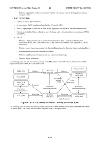
![3GPP TS 36.331 version 10.2.0 Release 10 22 ETSI TS 136 331 V10.2.0 (2011-07)
4.3 Services
4.3.1 Services provided to upper layers
The RRC protocol offers the following services to upper layers:
- Broadcast of common control information;
- Notification of UEs in RRC_IDLE, e.g. about a terminating call, for ETWS, for CMAS;
- Transfer of dedicated control information, i.e. information for one specific UE.
4.3.2 Services expected from lower layers
In brief, the following are the main services that RRC expects from lower layers:
- PDCP: integrity protection and ciphering;
- RLC: reliable and in-sequence transfer of information, without introducing duplicates and with support for
segmentation and concatenation.
Further details about the services provided by Packet Data Convergence Protocol layer (e.g. integrity and ciphering) are
provided in TS 36.323 [8]. The services provided by Radio Link Control layer (e.g. the RLC modes) are specified in TS
36.322 [7]. Further details about the services provided by Medium Access Control layer (e.g. the logical channels) are
provided in TS 36.321 [6]. The services provided by physical layer (e.g. the transport channels) are specified in TS
36.302 [3].
4.4 Functions
The RRC protocol includes the following main functions:
- Broadcast of system information:
- Including NAS common information;
- Information applicable for UEs in RRC_IDLE, e.g. cell (re-)selection parameters, neighbouring cell
information and information (also) applicable for UEs in RRC_CONNECTED, e.g. common channel
configuration information.
- Including ETWS notification, CMAS notification;
- RRC connection control:
- Paging;
- Establishment/ modification/ release of RRC connection, including e.g. assignment/ modification of UE
identity (C-RNTI), establishment/ modification/ release of SRB1 and SRB2, access class barring;
- Initial security activation, i.e. initial configuration of AS integrity protection (SRBs) and AS ciphering
(SRBs, DRBs);
- For RNs, configuration of AS integrity protection for DRBs;
- RRC connection mobility including e.g. intra-frequency and inter-frequency handover, associated security
handling, i.e. key/ algorithm change, specification of RRC context information transferred between network
nodes;
- Establishment/ modification/ release of RBs carrying user data (DRBs);
- Radio configuration control including e.g. assignment/ modification of ARQ configuration, HARQ
configuration, DRX configuration;
- For RNs, RN-specific radio configuration control for the radio interface between RN and E-UTRAN;
ETSI](https://image.slidesharecdn.com/ts136331v100200p-111014005410-phpapp02/85/Ts-136331v100200p-23-320.jpg)
![3GPP TS 36.331 version 10.2.0 Release 10 23 ETSI TS 136 331 V10.2.0 (2011-07)
- In case of CA, cell management including e.g. change of PCell and addition/ modification/ release of
SCell(s);
- QoS control including assignment/ modification of semi-persistent scheduling (SPS) configuration
information for DL and UL, assignment/ modification of parameters for UL rate control in the UE, i.e.
allocation of a priority and a prioritised bit rate (PBR) for each RB;
- Recovery from radio link failure;
- Inter-RAT mobility including e.g. security activation, transfer of RRC context information;
- Measurement configuration and reporting:
- Establishment/ modification/ release of measurements (e.g. intra-frequency, inter-frequency and inter- RAT
measurements);
- Setup and release of measurement gaps;
- Measurement reporting;
- Other functions including e.g. transfer of dedicated NAS information and non-3GPP dedicated information,
transfer of UE radio access capability information, support for E-UTRAN sharing (multiple PLMN identities);
- Generic protocol error handling;
- Support of self-configuration and self-optimisation;
- Support of measurement logging and reporting for network performance optimisation [60];
NOTE: Random access is specified entirely in the MAC including initial transmission power estimation.
5 Procedures
5.1 General
5.1.1 Introduction
The procedural requirements are structured according to the main functional areas: system information (5.2), connection
control (5.3), inter-RAT mobility (5.4) and measurements (5.5). In addition sub-clause 5.6 covers other aspects e.g.
NAS dedicated information transfer, UE capability transfer, sub-clause 5.7 specifies the generic error handling, sub-
clause 5.8 covers MBMS and sub-clause 5.9 specifies relays.
5.1.2 General requirements
The UE shall:
1> process the received messages in order of reception by RRC, i.e. the processing of a message shall be completed
before starting the processing of a subsequent message;
NOTE 1: E-UTRAN may initiate a subsequent procedure prior to receiving the UE's response of a previously
initiated procedure.
1> within a sub-clause execute the steps according to the order specified in the procedural description;
1> consider the term 'radio bearer' (RB) to cover SRBs and DRBs but not MRBs unless explicitly stated otherwise;
1> set the rrc-TransactionIdentifier in the response message, if included, to the same value as included in the
message received from E-UTRAN that triggered the response message;
1> upon receiving a choice value set to setup:
ETSI](https://image.slidesharecdn.com/ts136331v100200p-111014005410-phpapp02/85/Ts-136331v100200p-24-320.jpg)
![3GPP TS 36.331 version 10.2.0 Release 10 24 ETSI TS 136 331 V10.2.0 (2011-07)
2> apply the corresponding received configuration and start using the associated resources, unless explicitly
specified otherwise;
1> upon receiving a choice value set to release:
2> clear the corresponding configuration and stop using the associated resources;
1> upon handover to E-UTRA; or
1> upon receiving an RRCConnectionReconfiguration message including the fullConfig:
2> apply the Conditions in the ASN.1 for inclusion of the fields for the DRB/PDCP/RLC setup during the
reconfiguration of the DRBs included in the drb-ToAddModList;
NOTE 2: At each point in time, the UE keeps a single value for each field except for during handover when the UE
temporarily stores the previous configuration so it can revert back upon handover failure. In other words:
when the UE reconfigures a field, the existing value is released except for during handover.
NOTE 3: Although not explicitly stated, the UE initially considers all functionality to be deactivated/ released until
it is explicitly stated that the functionality is setup/ activated. Correspondingly, the UE initially considers
lists to be empty e.g. the list of radio bearers, the list of measurements.
5.2 System information
5.2.1 Introduction
5.2.1.1 General
System information is divided into the MasterInformationBlock (MIB) and a number of SystemInformationBlocks
(SIBs). The MIB includes a limited number of most essential and most frequently transmitted parameters that are
needed to acquire other information from the cell, and is transmitted on BCH. SIBs other than
SystemInformationBlockType1 are carried in SystemInformation (SI) messages and mapping of SIBs to SI messages is
flexibly configurable by schedulingInfoList included in SystemInformationBlockType1, with restrictions that: each SIB
is contained only in a single SI message, only SIBs having the same scheduling requirement (periodicity) can be
mapped to the same SI message, and SystemInformationBlockType2 is always mapped to the SI message that
corresponds to the first entry in the list of SI messages in schedulingInfoList. There may be multiple SI messages
transmitted with the same periodicity. SystemInformationBlockType1 and all SI messages are transmitted on DL-SCH.
NOTE 1: The physical layer imposes a limit to the maximum size a SIB can take. When DCI format 1C is used the
maximum allowed by the physical layer is 1736 bits (217 bytes) while for format 1A the limit is 2216 bits
(277 bytes), see TS 36.212 [22] and TS 36.213 [23].
The UE applies the system information acquisition and change monitoring procedures for the PCell only. For an SCell,
E-UTRAN provides, via dedicated signalling, all system information relevant for operation in RRC_CONNECTED
when adding the SCell. Upon change of the relevant system information of a configured SCell, E-UTRAN releases and
subsequently adds the concerned SCell, which may be done with a single RRCConnectionReconfiguration message.
NOTE 2: E-UTRAN may configure via dedicated signalling different parameter values than the ones broadcast in
the concerned SCell.
An RN configured with an RN subframe configuration does not need to apply the system information acquisition and
change monitoring procedures. Upon change of any system information relevant to an RN, E-UTRAN provides the
system information blocks containing the relevant system information to an RN configured with an RN subframe
configuration via dedicated signalling using the RNReconfiguration message. For RNs configured with an RN subframe
configuration, the system information contained in this dedicated signalling replaces any corresponding stored system
information and takes precedence over any corresponding system information acquired through the system information
acquisition procedure. The dedicated system information remains valid until overridden.
NOTE 3: E-UTRAN may configure an RN, via dedicated signalling, with different parameter values than the ones
broadcast in the concerned cell.
ETSI](https://image.slidesharecdn.com/ts136331v100200p-111014005410-phpapp02/85/Ts-136331v100200p-25-320.jpg)
![3GPP TS 36.331 version 10.2.0 Release 10 25 ETSI TS 136 331 V10.2.0 (2011-07)
5.2.1.2 Scheduling
The MIB uses a fixed schedule with a periodicity of 40 ms and repetitions made within 40 ms. The first transmission of
the MIB is scheduled in subframe #0 of radio frames for which the SFN mod 4 = 0, and repetitions are scheduled in
subframe #0 of all other radio frames.
The SystemInformationBlockType1 uses a fixed schedule with a periodicity of 80 ms and repetitions made within 80 ms.
The first transmission of SystemInformationBlockType1 is scheduled in subframe #5 of radio frames for which the SFN
mod 8 = 0, and repetitions are scheduled in subframe #5 of all other radio frames for which SFN mod 2 = 0.
The SI messages are transmitted within periodically occurring time domain windows (referred to as SI-windows) using
dynamic scheduling. Each SI message is associated with a SI-window and the SI-windows of different SI messages do
not overlap. That is, within one SI-window only the corresponding SI is transmitted. The length of the SI-window is
common for all SI messages, and is configurable. Within the SI-window, the corresponding SI message can be
transmitted a number of times in any subframe other than MBSFN subframes, uplink subframes in TDD, and subframe
#5 of radio frames for which SFN mod 2 = 0. The UE acquires the detailed time-domain scheduling (and other
information, e.g. frequency-domain scheduling, used transport format) from decoding SI-RNTI on PDCCH (see TS
36.321 [6]).
A single SI-RNTI is used to address SystemInformationBlockType1 as well as all SI messages.
SystemInformationBlockType1 configures the SI-window length and the transmission periodicity for the SI messages.
5.2.1.3 System information validity and notification of changes
Change of system information (other than for ETWS and CMAS) only occurs at specific radio frames, i.e. the concept
of a modification period is used. System information may be transmitted a number of times with the same content
within a modification period, as defined by its scheduling. The modification period boundaries are defined by SFN
values for which SFN mod m= 0, where m is the number of radio frames comprising the modification period. The
modification period is configured by system information.
When the network changes (some of the) system information, it first notifies the UEs about this change, i.e. this may be
done throughout a modification period. In the next modification period, the network transmits the updated system
information. These general principles are illustrated in figure 5.2.1.3-1, in which different colours indicate different
system information. Upon receiving a change notification, the UE acquires the new system information immediately
from the start of the next modification period. The UE applies the previously acquired system information until the UE
acquires the new system information.
Change notification Updated information
BCCH modification period (n) BCCH modification period (n+1)
Figure 5.2.1.3-1: Change of system Information
The Paging message is used to inform UEs in RRC_IDLE and UEs in RRC_CONNECTED about a system information
change. If the UE receives a Paging message including the systemInfoModification, it knows that the system
information will change at the next modification period boundary. Although the UE may be informed about changes in
system information, no further details are provided e.g. regarding which system information will change.
SystemInformationBlockType1 includes a value tag, systemInfoValueTag, that indicates if a change has occurred in the
SI messages. UEs may use systemInfoValueTag, e.g. upon return from out of coverage, to verify if the previously stored
SI messages are still valid. Additionally, the UE considers stored system information to be invalid after 3 hours from the
moment it was successfully confirmed as valid, unless specified otherwise.
E-UTRAN may not update systemInfoValueTag upon change of some system information e.g. ETWS information,
CMAS information, regularly changing parameters like CDMA2000 system time (see 6.3). Similarly, E-UTRAN may
not include the systemInfoModification within the Paging message upon change of some system information.
ETSI](https://image.slidesharecdn.com/ts136331v100200p-111014005410-phpapp02/85/Ts-136331v100200p-26-320.jpg)
![3GPP TS 36.331 version 10.2.0 Release 10 26 ETSI TS 136 331 V10.2.0 (2011-07)
The UE verifies that stored system information remains valid by either checking systemInfoValueTag in
SystemInformationBlockType1 after the modification period boundary, or attempting to find the systemInfoModification
indication at least modificationPeriodCoeff times during the modification period in case no paging is received, in every
modification period. If no paging message is received by the UE during a modification period, the UE may assume that
no change of system information will occur at the next modification period boundary. If UE in RRC_CONNECTED,
during a modification period, receives one paging message, it may deduce from the presence/ absence of
systemInfoModification whether a change of system information other than ETWS and CMAS information will occur in
the next modification period or not.
ETWS and/or CMAS capable UEs in RRC_CONNECTED shall attempt to read paging at least once every
defaultPagingCycle to check whether ETWS and/or CMAS notification is present or not.
5.2.1.4 Indication of ETWS notification
ETWS primary notification and/ or ETWS secondary notification can occur at any point in time. The Paging message is
used to inform ETWS capable UEs in RRC_IDLE and UEs in RRC_CONNECTED about presence of an ETWS
primary notification and/ or ETWS secondary notification. If the UE receives a Paging message including the etws-
Indication, it shall start receiving the ETWS primary notification and/ or ETWS secondary notification according to
schedulingInfoList contained in SystemInformationBlockType1.
ETWS primary notification is contained in SystemInformationBlockType10 and ETWS secondary notification is
contained in SystemInformationBlockType11. Segmentation can be applied for the delivery of a secondary notification.
The segmentation is fixed for transmission of a given secondary notification within a cell (i.e. the same segment size for
a given segment with the same messageIdentifier, serialNumber and warningMessageSegmentNumber). An ETWS
secondary notification corresponds to a single CB data IE as defined according to TS 23.041 [37].
5.2.1.5 Indication of CMAS notification
CMAS notification can occur at any point in time. The Paging message is used to inform CMAS capable UEs in
RRC_IDLE and UEs in RRC_CONNECTED about presence of one or more CMAS notifications. If the UE receives a
Paging message including the cmas-Indication, it shall start receiving the CMAS notifications according to
schedulingInfoList contained in SystemInformationBlockType1.
CMAS notification is contained in SystemInformationBlockType12. Segmentation can be applied for the delivery of a
CMAS notification. The segmentation is fixed for transmission of a given CMAS notification within a cell (i.e. the
same segment size for a given segment with the same messageIdentifier, serialNumber and
warningMessageSegmentNumber). E-UTRAN does not interleave transmissions of CMAS notifications, i.e. all
segments of a given CMAS notification transmission are transmitted prior to those of another CMAS notification. A
CMAS notification corresponds to a single CB data IE as defined according to TS 23.041 [37].
5.2.2 System information acquisition
5.2.2.1 General
UE E-UTRAN
MasterInformationBlock
SystemInformationBlockType1
SystemInformation
Figure 5.2.2.1-1: System information acquisition, normal
The UE applies the system information acquisition procedure to acquire the AS- and NAS- system information that is
broadcasted by the E-UTRAN. The procedure applies to UEs in RRC_IDLE and UEs in RRC_CONNECTED.
ETSI](https://image.slidesharecdn.com/ts136331v100200p-111014005410-phpapp02/85/Ts-136331v100200p-27-320.jpg)
![3GPP TS 36.331 version 10.2.0 Release 10 29 ETSI TS 136 331 V10.2.0 (2011-07)
1> if in RRC_IDLE or in RRC_CONNECTED while T311 is running:
2> if the UE is unable to acquire the MasterInformationBlock or the SystemInformationBlockType1:
3> consider the cell as barred in accordance with TS 36.304 [4] and;
3> perform barring as if intraFreqReselection is set to allowed, and as if the csg-Indication is set to FALSE;
2> else if the UE is unable to acquire the SystemInformationBlockType2:
3> treat the cell as barred in accordance with TS 36.304 [4];
5.2.2.6 Actions upon reception of the MasterInformationBlock message
Upon receiving the MasterInformationBlock message the UE shall:
1> apply the radio resource configuration included in the phich-Config;
1> if the UE is in RRC_IDLE or if the UE is in RRC_CONNECTED while T311 is running:
2> if the UE has no valid system information stored according to 5.2.2.3 for the concerned cell:
3> apply the received value of dl-Bandwidth to the ul-Bandwidth until SystemInformationBlockType2 is
received;
5.2.2.7 Actions upon reception of the SystemInformationBlockType1 message
Upon receiving the SystemInformationBlockType1 message the UE shall:
1> if the frequency band indicated in the freqBandIndicator is not part of the frequency bands supported by the UE:
2> consider the cell as barred in accordance with TS 36.304 [4] and;
2> perform barring as if intraFreqReselection is set to notAllowed, and as if the csg-Indication is set to FALSE;
1> else:
2> forward the cellIdentity to upper layers;
2> forward the trackingAreaCode to upper layers;
5.2.2.8 Actions upon reception of SystemInformation messages
No UE requirements related to the contents of the SystemInformation messages apply other than those specified
elsewhere e.g. within procedures using the concerned system information, and/ or within the corresponding field
descriptions.
5.2.2.9 Actions upon reception of SystemInformationBlockType2
Upon receiving SystemInformationBlockType2, the UE shall:
1> apply the configuration included in the radioResourceConfigCommon;
1> if upper layers indicate that a (UE specific) paging cycle is configured:
2> apply the shortest of the (UE specific) paging cycle and the defaultPagingCycle included in the
radioResourceConfigCommon;
1> if the mbsfn-SubframeConfigList is included:
2> consider that DL assignments may occur in the MBSFN subframes indicated in the mbsfn-
SubframeConfigList under the conditions specified in [23, 7.1];
1> apply the specified PCCH configuration defined in 9.1.1.3;
ETSI](https://image.slidesharecdn.com/ts136331v100200p-111014005410-phpapp02/85/Ts-136331v100200p-30-320.jpg)
![3GPP TS 36.331 version 10.2.0 Release 10 34 ETSI TS 136 331 V10.2.0 (2011-07)
activation and/ or the radio bearer establishment fails (i.e. security activation and DRB establishment are triggered by a
joint S1-procedure, which does not support partial success).
For SRB2 and DRBs, security is always activated from the start, i.e. the E-UTRAN does not establish these bearers
prior to activating security.
After having initiated the initial security activation procedure, E-UTRAN may configure a UE that supports CA, with
one or more SCells in addition to the PCell that was initially configured during connection establishment. The PCell is
used to provide the security inputs and upper layer system information (i.e. the NAS mobility information e.g. TAI).
SCells are used to provide additional downlink and optionally uplink radio resources.
The release of the RRC connection normally is initiated by E-UTRAN. The procedure may be used to re-direct the UE
to an E-UTRA frequency or an inter-RAT carrier frequency. Only in exceptional cases, as specified within this
specification, TS 36.300 [9], TS 36.304 [4] or TS 24.301 [35], may the UE abort the RRC connection, i.e. move to
RRC_IDLE without notifying E-UTRAN.
5.3.1.2 Security
AS security comprises of the integrity protection of RRC signalling (SRBs) as well as the ciphering of RRC signalling
(SRBs) and user data (DRBs).
RRC handles the configuration of the security parameters which are part of the AS configuration: the integrity
protection algorithm, the ciphering algorithm and two parameters, namely the keyChangeIndicator and the
nextHopChainingCount, which are used by the UE to determine the AS security keys upon handover and/ or connection
re-establishment.
The integrity protection algorithm is common for signalling radio bearers SRB1 and SRB2. The ciphering algorithm is
common for all radio bearers (i.e. SRB1, SRB2 and DRBs). Neither integrity protection nor ciphering applies for SRB0.
RRC integrity and ciphering are always activated together, i.e. in one message/ procedure. RRC integrity and ciphering
are never de-activated. However, it is possible to switch to a 'NULL' ciphering algorithm (eea0).
The 'NULL' integrity protection algorithm (eia0) is used only for the UE in limited service mode [32, TS33.401]. In
case the 'NULL' integrity protection algorithm is used, 'NULL' ciphering algorithm is also used.
NOTE 1: Lower layers discard RRC messages for which the integrity check has failed and indicate the integrity
verification check failure to RRC.
The AS applies three different security keys: one for the integrity protection of RRC signalling (KRRCint), one for the
ciphering of RRC signalling (KRRCenc) and one for the ciphering of user data (KUPenc). All three AS keys are derived
from the KeNB key. The KeNB is based on the KASME key, which is handled by upper layers.
Upon connection establishment new AS keys are derived. No AS-parameters are exchanged to serve as inputs for the
derivation of the new AS keys at connection establishment.
The integrity and ciphering of the RRC message used to perform handover is based on the security configuration used
prior to the handover and is performed by the source eNB.
The integrity and ciphering algorithms can only be changed upon handover. The four AS keys (KeNB, KRRCint, KRRCenc
and KUPenc) change upon every handover and connection re-establishment. The keyChangeIndicator is used upon
handover and indicates whether the UE should use the keys associated with the latest available KASME key. The
nextHopChainingCount parameter is used upon handover and connection re-establishment by the UE when deriving the
new KeNB that is used to generate KRRCint, KRRCenc and KUPenc (see TS 33.401 [32]). An intra cell handover procedure may
be used to change the keys in RRC_CONNECTED.
For each radio bearer an independent counter (COUNT, as specified in TS 36.323 [8]) is maintained for each direction.
For each DRB, the COUNT is used as input for ciphering. For each SRB, the COUNT is used as input for both
ciphering and integrity protection. It is not allowed to use the same COUNT value more than once for a given security
key. In order to limit the signalling overhead, individual messages/ packets include a short sequence number (PDCP
SN, as specified in TS 36.323 [8]). In addition, an overflow counter mechanism is used: the hyper frame number
(TX_HFN and RX_HFN, as specified in TS 36.323 [8]). The HFN needs to be synchronized between the UE and the
eNB. The eNB is responsible for avoiding reuse of the COUNT with the same RB identity and with the same KeNB, e.g.
due to the transfer of large volumes of data, release and establishment of new RBs. In order to avoid such re-use, the
ETSI](https://image.slidesharecdn.com/ts136331v100200p-111014005410-phpapp02/85/Ts-136331v100200p-35-320.jpg)
![3GPP TS 36.331 version 10.2.0 Release 10 35 ETSI TS 136 331 V10.2.0 (2011-07)
eNB may e.g. use different RB identities for successive RB establishments, trigger an intra cell handover or an
RRC_CONNECTED to RRC_IDLE to RRC_CONNECTED transition.
For each SRB, the value provided by RRC to lower layers to derive the 5-bit BEARER parameter used as input for
ciphering and for integrity protection is the value of the corresponding srb-Identity with the MSBs padded with zeroes.
5.3.1.2a RN security
For RNs, AS security follows the procedures in 5.3.1.2. Furthermore, E-UTRAN may configure per DRB whether or
not integrity protection is used. The use of integrity protection may be configured only upon DRB establishment and
reconfigured only upon handover or upon the first reconfiguration following RRC connection re-establishment.
To provide integrity protection on DRBs between the RN and the E-UTRAN, the KUPint key is derived from the KeNB
key as described in TS33.401 [32]. The same integrity protection algorithm used for SRBs also applies to the DRBs.
The KUPint changes at every handover and RRC connection re-establishment and is based on an updated KeNB which is
derived by taking into account the nextHopChainingCount. The COUNT value maintained for DRB ciphering is also
used for integrity protection, if the integrity protection is configured for the DRB.
5.3.1.3 Connected mode mobility
In RRC_CONNECTED, the network controls UE mobility, i.e. the network decides when the UE shall connect to
which E-UTRA cell(s), or inter-RAT cell. For network controlled mobility in RRC_CONNECTED, the PCell can be
changed using an RRCConnectionReconfiguration message including the mobilityControlInfo (handover), whereas the
SCell(s) can be changed using the RRCConnectionReconfiguration message either with or without the
mobilityControlInfo. The network triggers the handover procedure e.g. based on radio conditions, load. To facilitate
this, the network may configure the UE to perform measurement reporting (possibly including the configuration of
measurement gaps). The network may also initiate handover blindly, i.e. without having received measurement reports
from the UE.
Before sending the handover message to the UE, the source eNB prepares one or more target cells. The source eNB
selects the target PCell. The source eNB may also provide the target eNB with a list of best cells on each frequency for
which measurement information is available, in order of decreasing RSRP. The source eNB may also include available
measurement information for the cells provided in the list. The target eNB decides which SCells are configured for use
after handover, which may include cells other than the ones indicated by the source eNB.
The target eNB generates the message used to perform the handover, i.e. the message including the AS-configuration to
be used in the target cell(s). The source eNB transparently (i.e. does not alter values/ content) forwards the handover
message/ information received from the target to the UE. When appropriate, the source eNB may initiate data
forwarding for (a subset of) the DRBs.
After receiving the handover message, the UE attempts to access the target PCell at the first available RACH occasion
according to Random Access resource selection defined in TS 36.321 [6], i.e. the handover is asynchronous.
Consequently, when allocating a dedicated preamble for the random access in the target PCell, E-UTRA shall ensure it
is available from the first RACH occasion the UE may use. Upon successful completion of the handover, the UE sends
a message used to confirm the handover.
If the target eNB does not support the release of RRC protocol which the source eNB used to configure the UE, the
target eNB may be unable to comprehend the UE configuration provided by the source eNB. In this case, the target eNB
should use the full configuration option to reconfigure the UE for Handover and Re-establishment. Full configuration
option includes an initialization of the radio configuration, which makes the procedure independent of the configuration
used in the source cell(s) with the exception that the security algorithms are continued for the RRC re-establishment.
After the successful completion of handover, PDCP SDUs may be re-transmitted in the target cell(s). This only applies
for DRBs using RLC-AM mode and for handovers not involving full configuration option. The further details are
specified in TS 36.323 [8]. After the successful completion of handover not involving full configuration option, the SN
and the HFN are reset except for the DRBs using RLC-AM mode (for which both SN and HFN continue). For
reconfigurations involving the full configuration option, the PDCP entities are newly established (SN and HFN do not
continue) for all DRBs irrespective of the RLC mode. The further details are specified in TS 36.323 [8].
One UE behaviour to be performed upon handover is specified, i.e. this is regardless of the handover procedures used
within the network (e.g. whether the handover includes X2 or S1 signalling procedures).
ETSI](https://image.slidesharecdn.com/ts136331v100200p-111014005410-phpapp02/85/Ts-136331v100200p-36-320.jpg)
![3GPP TS 36.331 version 10.2.0 Release 10 36 ETSI TS 136 331 V10.2.0 (2011-07)
The source eNB should, for some time, maintain a context to enable the UE to return in case of handover failure. After
having detected handover failure, the UE attempts to resume the RRC connection either in the source PCell or in
another cell using the RRC re-establishment procedure. This connection resumption succeeds only if the accessed cell is
prepared, i.e. concerns a cell of the source eNB or of another eNB towards which handover preparation has been
performed. The cell in which the re-establishment procedure succeeds becomes the PCell while SCells, if configured,
are released.
Normal measurement and mobility procedures are used to support handover to cells broadcasting a CSG identity. In
addition, E-UTRAN may configure the UE to report that it is entering or leaving the proximity of cell(s) included in its
CSG whitelist. Furthermore, E-UTRAN may request the UE to provide additional information broadcast by the
handover candidate cell e.g. cell global identity, CSG identity, CSG membership status.
NOTE E-UTRAN may use the ‘proximity report’ to configure measurements as well as to decide whether or not
to request additional information broadcast by the handover candidate cell. The additional information is
used to verify whether or not the UE is authorised to access the target PCell and may also be needed to
identify handover candidate cell (PCI confusion i.e. when the physical layer identity that is included in
the measurement report does not uniquely identify the cell).
5.3.2 Paging
5.3.2.1 General
UE EUTRAN
Paging
Figure 5.3.2.1-1: Paging
The purpose of this procedure is:
- to transmit paging information to a UE in RRC_IDLE and/ or;
- to inform UEs in RRC_IDLE and UEs in RRC_CONNECTED about a system information change and/ or;
- to inform about an ETWS primary notification and/ or ETWS secondary notification and/ or;
- to inform about a CMAS notification.
The paging information is provided to upper layers, which in response may initiate RRC connection establishment, e.g.
to receive an incoming call.
5.3.2.2 Initiation
E-UTRAN initiates the paging procedure by transmitting the Paging message at the UE's paging occasion as specified
in TS 36.304 [4]. E-UTRAN may address multiple UEs within a Paging message by including one PagingRecord for
each UE. E-UTRAN may also indicate a change of system information, and/ or provide an ETWS notification or a
CMAS notification in the Paging message.
5.3.2.3 Reception of the Paging message by the UE
Upon receiving the Paging message, the UE shall:
1> if in RRC_IDLE, for each of the PagingRecord, if any, included in the Paging message:
2> if the ue-Identity included in the PagingRecord matches one of the UE identities allocated by upper layers:
ETSI](https://image.slidesharecdn.com/ts136331v100200p-111014005410-phpapp02/85/Ts-136331v100200p-37-320.jpg)
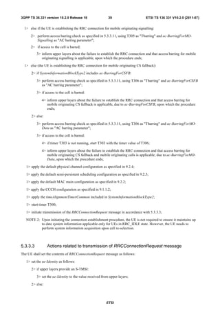
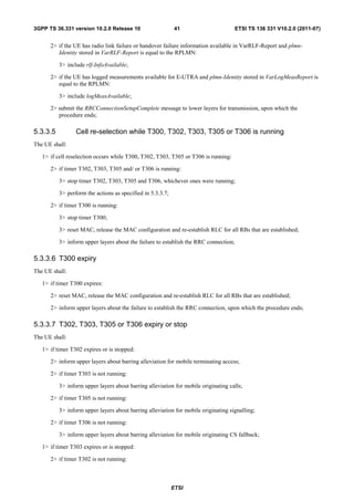
![3GPP TS 36.331 version 10.2.0 Release 10 38 ETSI TS 136 331 V10.2.0 (2011-07)
The purpose of this procedure is to establish an RRC connection. RRC connection establishment involves SRB1
establishment. The procedure is also used to transfer the initial NAS dedicated information/ message from the UE to E-
UTRAN.
E-UTRAN applies the procedure as follows:
- to establish SRB1 only.
5.3.3.2 Initiation
The UE initiates the procedure when upper layers request establishment of an RRC connection while the UE is in
RRC_IDLE.
Upon initiation of the procedure, the UE shall:
1> if the UE is establishing the RRC connection for mobile terminating calls:
2> if timer T302 is running:
3> inform upper layers about the failure to establish the RRC connection and that access barring for mobile
terminating calls is applicable, upon which the procedure ends;
1> else if the UE is establishing the RRC connection for emergency calls:
2> if SystemInformationBlockType2 includes the ac-BarringInfo:
3> if the ac-BarringForEmergency is set to TRUE:
4> if the UE has one or more Access Classes, as stored on the USIM, with a value in the range 11..15,
which is valid for the UE to use according to TS 22.011 [10] and TS 23.122 [11]:
NOTE 1: ACs 12, 13, 14 are only valid for use in the home country and ACs 11, 15 are only valid for use in the
HPLMN/ EHPLMN.
5> if the ac-BarringInfo includes ac-BarringForMO-Data, and for all of these valid Access Classes
for the UE, the corresponding bit in the ac-BarringForSpecialAC contained in ac-BarringForMO-
Data is set to one:
6> consider access to the cell as barred;
4> else:
5> consider access to the cell as barred;
2> if access to the cell is barred:
3> inform upper layers about the failure to establish the RRC connection, upon which the procedure ends;
1> else if the UE is establishing the RRC connection for mobile originating calls:
2> perform access barring check as specified in 5.3.3.11, using T303 as "Tbarring" and ac-BarringForMO-Data
as "AC barring parameter";
2> if access to the cell is barred:
3> if SystemInformationBlockType2 includes ac-BarringForCSFB or the UE does not support CS fallback:
4> inform upper layers about the failure to establish the RRC connection and that access barring for mobile
originating calls is applicable, upon which the procedure ends;
3> else (SystemInformationBlockType2 does not include ac-BarringForCSFB and the UE supports CS
fallback):
4> if timer T306 is not running, start T306 with the timer value of T303;
4> inform upper layers about the failure to establish the RRC connection and that access barring for mobile
originating calls and mobile originating CS fallback is applicable, upon which the procedure ends;
ETSI](https://image.slidesharecdn.com/ts136331v100200p-111014005410-phpapp02/85/Ts-136331v100200p-39-320.jpg)
![3GPP TS 36.331 version 10.2.0 Release 10 40 ETSI TS 136 331 V10.2.0 (2011-07)
3> draw a random value in the range 0 .. 240-1 and set the ue-Identity to this value;
NOTE 1: Upper layers provide the S-TMSI if the UE is registered in the TA of the current cell.
1> set the establishmentCause in accordance with the information received from upper layers;
The UE shall submit the RRCConnectionRequest message to lower layers for transmission.
The UE shall continue cell re-selection related measurements as well as cell re-selection evaluation. If the conditions for
cell re-selection are fulfilled, the UE shall perform cell re-selection as specified in 5.3.3.5.
5.3.3.4 Reception of the RRCConnectionSetup by the UE
NOTE: Prior to this, lower layer signalling is used to allocate a C-RNTI. For further details see TS 36.321 [6];
The UE shall:
1> perform the radio resource configuration procedure in accordance with the received
radioResourceConfigDedicated and as specified in 5.3.10;
1> if stored, discard the cell reselection priority information provided by the idleModeMobilityControlInfo or
inherited from another RAT;
1> stop timer T300;
1> stop timer T302, if running;
1> stop timer T303, if running;
1> stop timer T305, if running;
1> stop timer T306, if running;
1> perform the actions as specified in 5.3.3.7;
1> stop timer T320, if running;
1> enter RRC_CONNECTED;
1> stop the cell re-selection procedure;
1> consider the current cell to be the PCell;
1> set the content of RRCConnectionSetupComplete message as follows:
2> set the selectedPLMN-Identity to the PLMN selected by upper layers (see TS 23.122 [11], TS 24.301 [35])
from the PLMN(s) included in the plmn-IdentityList in SystemInformationBlockType1;
2> if upper layers provide the 'Registered MME', include and set the registeredMME as follows:
3> if the PLMN identity of the 'Registered MME' is different from the PLMN selected by the upper layers:
4> include the plmnIdentity in the registeredMME and set it to the value of the PLMN identity in the
'Registered MME' received from upper layers;
3> set the mmegi and the mmec to the value received from upper layers;
2> if upper layers provided the 'Registered MME':
3> include and set the gummei-Type to the value provided by the upper layers;
2> if connecting as an RN:
3> include the rn-SubframeConfigReq;
2> set the dedicatedInfoNAS to include the information received from upper layers;
ETSI](https://image.slidesharecdn.com/ts136331v100200p-111014005410-phpapp02/85/Ts-136331v100200p-41-320.jpg)
![3GPP TS 36.331 version 10.2.0 Release 10 42 ETSI TS 136 331 V10.2.0 (2011-07)
3> inform upper layers about barring alleviation for mobile originating calls;
1> if timer T305 expires or is stopped:
2> if timer T302 is not running:
3> inform upper layers about barring alleviation for mobile originating signalling;
1> if timer T306 expires or is stopped:
2> if timer T302 is not running:
3> inform upper layers about barring alleviation for mobile originating CS fallback;
5.3.3.8 Reception of the RRCConnectionReject by the UE
The UE shall:
1> stop timer T300;
1> reset MAC and release the MAC configuration;
1> start timer T302, with the timer value set to the waitTime;
1> if the extendedWaitTime is present and the UE supports delay tolerant access:
2> forward the extendedWaitTime to upper layers;
1> inform upper layers about the failure to establish the RRC connection and that access barring for mobile
originating calls, mobile originating signalling, mobile terminating access and mobile originating CS fallback is
applicable, upon which the procedure ends;
5.3.3.9 Abortion of RRC connection establishment
If upper layers abort the RRC connection establishment procedure while the UE has not yet entered
RRC_CONNECTED, the UE shall:
1> stop timer T300, if running;
1> reset MAC, release the MAC configuration and re-establish RLC for all RBs that are established;
5.3.3.10 Handling of SSAC related parameters
Upon request from the upper layers, the UE shall:
1> set the local variables BarringFactorForMMTEL-Voice and BarringTimeForMMTEL-Voice as follows:
2> if the UE is in RRC_IDLE and ssac-BarringForMMTEL-Voice is present:
3> if the UE has one or more Access Classes, as stored on the USIM, with a value in the range 11..15, which
is valid for the UE to use according to TS 22.011 [10] and TS 23.122 [11], and
NOTE: ACs 12, 13, 14 are only valid for use in the home country and ACs 11, 15 are only valid for use in the
HPLMN/ EHPLMN.
3> if, for at least one of these Access Classes, the corresponding bit in the ac-BarringForSpecialAC
contained in ssac-BarringForMMTEL-Voice is set to zero:
4> set BarringFactorForMMTEL-Voice to one and BarringTimeForMMTEL-Voice to zero;
3> else:
4> set BarringFactorForMMTEL-Voice and BarringTimeForMMTEL-Voice to the value of ac-
BarringFactor and ac-BarringTime included in ssac-BarringForMMTEL-Voice, respectively;
2> else set BarringFactorForMMTEL-Voice to one and BarringTimeForMMTEL-Voice to zero;
ETSI](https://image.slidesharecdn.com/ts136331v100200p-111014005410-phpapp02/85/Ts-136331v100200p-43-320.jpg)
![3GPP TS 36.331 version 10.2.0 Release 10 43 ETSI TS 136 331 V10.2.0 (2011-07)
1> set the local variables BarringFactorForMMTEL-Video and BarringTimeForMMTEL-Video as follows:
2> if the UE is in RRC_IDLE and ssac-BarringForMMTEL-Video is present:
3> if the UE has one or more Access Classes, as stored on the USIM, with a value in the range 11..15, which
is valid for the UE to use according to TS 22.011 [10] and TS 23.122 [11], and
3> if, for at least one of these Access Classes, the corresponding bit in the ac-BarringForSpecialAC
contained in ssac-BarringForMMTEL-Video is set to zero:
4> set BarringFactorForMMTEL-Video to one and BarringTimeForMMTEL-Video to zero;
3> else:
4> set BarringFactorForMMTEL-Video and BarringTimeForMMTEL-Video to the value of ac-
BarringFactor and ac-BarringTime included in ssac-BarringForMMTEL-Video, respectively;
2> else set BarringFactorForMMTEL-Video to one and BarringTimeForMMTEL-Video to zero;
1> forward the variables BarringFactorForMMTEL-Voice, BarringTimeForMMTEL-Voice,
BarringFactorForMMTEL-Video and BarringTimeForMMTEL-Video to the upper layers;
5.3.3.11 Access barring check
1> if timer T302 or "Tbarring" is running:
2> consider access to the cell as barred;
1> else if SystemInformationBlockType2 includes "AC barring parameter":
2> if the UE has one or more Access Classes, as stored on the USIM, with a value in the range 11..15, which is
valid for the UE to use according to TS 22.011 [10] and TS 23.122 [11], and
NOTE: ACs 12, 13, 14 are only valid for use in the home country and ACs 11, 15 are only valid for use in the
HPLMN/ EHPLMN.
2> for at least one of these valid Access Classes the corresponding bit in the ac-BarringForSpecialAC contained
in "AC barring parameter" is set to zero:
3> consider access to the cell as not barred;
2> else:
3> draw a random number 'rand' uniformly distributed in the range: 0 ≤ rand < 1;
3> if 'rand' is lower than the value indicated by ac-BarringFactor included in "AC barring parameter":
4> consider access to the cell as not barred;
3> else:
4> consider access to the cell as barred;
1> else:
2> consider access to the cell as not barred;
1> if access to the cell is barred and both timers T302 and "Tbarring" are not running:
2> draw a random number 'rand' that is uniformly distributed in the range 0 ≤ rand < 1;
2> start timer "Tbarring" with the timer value calculated as follows, using the ac-BarringTime included in "AC
barring parameter":
"Tbarring" = (0.7+ 0.6 * rand) * ac-BarringTime.
ETSI](https://image.slidesharecdn.com/ts136331v100200p-111014005410-phpapp02/85/Ts-136331v100200p-44-320.jpg)
![3GPP TS 36.331 version 10.2.0 Release 10 44 ETSI TS 136 331 V10.2.0 (2011-07)
5.3.4 Initial security activation
5.3.4.1 General
UE EUTRAN
SecurityModeCommand
SecurityModeComplete
Figure 5.3.4.1-1: Security mode command, successful
UE EUTRAN
SecurityModeCommand
SecurityModeFailure
Figure 5.3.4.1-2: Security mode command, failure
The purpose of this procedure is to activate AS security upon RRC connection establishment.
5.3.4.2 Initiation
E-UTRAN initiates the security mode command procedure to a UE in RRC_CONNECTED. Moreover, E-UTRAN
applies the procedure as follows:
- when only SRB1 is established, i.e. prior to establishment of SRB2 and/ or DRBs.
5.3.4.3 Reception of the SecurityModeCommand by the UE
The UE shall:
1> derive the KeNB key, as specified in TS 33.401 [32];
1> derive the KRRCint key associated with the integrityProtAlgorithm indicated in the SecurityModeCommand
message, as specified in TS 33.401 [32];
1> request lower layers to verify the integrity protection of the SecurityModeCommand message, using the
algorithm indicated by the integrityProtAlgorithm as included in the SecurityModeCommand message and the
KRRCint key;
1> if the SecurityModeCommand message passes the integrity protection check:
2> derive the KRRCenc key and the KUPenc key associated with the cipheringAlgorithm indicated in the
SecurityModeCommand message, as specified in TS 33.401 [32];
2> if connected as an RN:
ETSI](https://image.slidesharecdn.com/ts136331v100200p-111014005410-phpapp02/85/Ts-136331v100200p-45-320.jpg)
![3GPP TS 36.331 version 10.2.0 Release 10 45 ETSI TS 136 331 V10.2.0 (2011-07)
3> derive the KUPint key associated with the integrityProtAlgorithm indicated in the SecurityModeCommand
message, as specified in TS 33.401 [32];
2> configure lower layers to apply integrity protection using the indicated algorithm and the KRRCint key
immediately, i.e. integrity protection shall be applied to all subsequent messages received and sent by the UE,
including the SecurityModeComplete message;
2> configure lower layers to apply ciphering using the indicated algorithm, the KRRCenc key and the KUPenc key
after completing the procedure, i.e. ciphering shall be applied to all subsequent messages received and sent
by the UE, except for the SecurityModeComplete message which is sent unciphered;
2> if connected as an RN:
3> configure lower layers to apply integrity protection using the indicated algorithm and the KUPint key, for
DRBs that are subsequently configured to apply integrity protection, if any;
2> consider AS security to be activated;
2> submit the SecurityModeComplete message to lower layers for transmission, upon which the procedure ends;
1> else:
2> continue using the configuration used prior to the reception of the SecurityModeCommand message, i.e.
neither apply integrity protection nor ciphering.
2> submit the SecurityModeFailure message to lower layers for transmission, upon which the procedure ends;
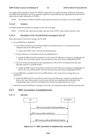
5.3.5 RRC connection reconfiguration
5.3.5.1 General
UE EUTRAN
RRCConnectionReconfiguration
RRCConnectionReconfigurationComplete
Figure 5.3.5.1-1: RRC connection reconfiguration, successful
UE EUTRAN
RRCConnectionReconfiguration
RRC connection re-establishment
Figure 5.3.5.1-2: RRC connection reconfiguration, failure
The purpose of this procedure is to modify an RRC connection, e.g. to establish/ modify/ release RBs, to perform
handover, to setup/ modify/ release measurements, to add/ modify/ release SCells. As part of the procedure, NAS
dedicated information may be transferred from E-UTRAN to the UE.
ETSI](https://image.slidesharecdn.com/ts136331v100200p-111014005410-phpapp02/85/Ts-136331v100200p-46-320.jpg)
![3GPP TS 36.331 version 10.2.0 Release 10 46 ETSI TS 136 331 V10.2.0 (2011-07)
5.3.5.2 Initiation
E-UTRAN may initiate the RRC connection reconfiguration procedure to a UE in RRC_CONNECTED. E-UTRAN
applies the procedure as follows:
- the mobilityControlInfo is included only when AS-security has been activated, and SRB2 with at least one DRB
are setup and not suspended;
- the establishment of RBs (other than SRB1, that is established during RRC connection establishment) is included
only when AS security has been activated;
- the addition of SCells is performed only when AS security has been activated;
5.3.5.3 Reception of an RRCConnectionReconfiguration not including the
mobilityControlInfo by the UE
If the RRCConnectionReconfiguration message does not include the mobilityControlInfo and the UE is able to comply
with the configuration included in this message, the UE shall:
1> if this is the first RRCConnectionReconfiguration message after successful completion of the RRC Connection
Re-establishment procedure:
2> re-establish PDCP for SRB2 and for all DRBs that are established, if any;
2> re-establish RLC for SRB2 and for all DRBs that are established, if any;
2> if the RRCConnectionReconfiguration message includes the fullConfig:
3> perform the radio configuration procedure as specified in section 5.3.5.8;
2> if the RRCConnectionReconfiguration message includes the radioResourceConfigDedicated:
3> perform the radio resource configuration procedure as specified in 5.3.10;
2> resume SRB2 and all DRBs that are suspended, if any;
NOTE 1: The handling of the radio bearers after the successful completion of the PDCP re-establishment, e.g. the
re-transmission of unacknowledged PDCP SDUs (as well as the associated status reporting), the handling
of the SN and the HFN, is specified in TS 36.323 [8].
1> else:
2> if the RRCConnectionReconfiguration message includes the radioResourceConfigDedicated:
3> perform the radio resource configuration procedure as specified in 5.3.10;
NOTE 2: If the RRCConnectionReconfiguration message includes the establishment of radio bearers other than
SRB1, the UE may start using these radio bearers immediately, i.e. there is no need to wait for an
outstanding acknowledgment of the SecurityModeComplete message.
1> if the received RRCConnectionReconfiguration includes the sCellToReleaseList:
2> perform SCell release as specified in 5.3.10.3a;
1> if the received RRCConnectionReconfiguration includes the sCellToAddModList:
2> perform SCell addition or modification as specified in 5.3.10.3b;
1> if the RRCConnectionReconfiguration message includes the dedicatedInfoNASList:
2> forward each element of the dedicatedInfoNASList to upper layers in the same order as listed;
1> if the RRCConnectionReconfiguration message includes the measConfig:
2> perform the measurement configuration procedure as specified in 5.5.2;
1> perform the measurement identity autonomous removal as specified in 5.5.2.2a;
ETSI](https://image.slidesharecdn.com/ts136331v100200p-111014005410-phpapp02/85/Ts-136331v100200p-47-320.jpg)
![3GPP TS 36.331 version 10.2.0 Release 10 47 ETSI TS 136 331 V10.2.0 (2011-07)
1> if the RRCConnectionReconfiguration message includes the reportProximityConfig:
2> perform the proximity indication in accordance with the received reportProximityConfig;
1> submit the RRCConnectionReconfigurationComplete message to lower layers for transmission using the new
configuration, upon which the procedure ends;
5.3.5.4 Reception of an RRCConnectionReconfiguration including the
mobilityControlInfo by the UE (handover)
If the RRCConnectionReconfiguration message includes the mobilityControlInfo and the UE is able to comply with the
configuration included in this message, the UE shall:
1> stop timer T310, if running;
1> start timer T304 with the timer value set to t304, as included in the mobilityControlInfo;
1> if the carrierFreq is included:
2> consider the target PCell to be one on the frequency indicated by the carrierFreq with a physical cell identity
indicated by the targetPhysCellId;
1> else:
2> consider the target PCell to be one on the frequency of the source PCell with a physical cell identity indicated
by the targetPhysCellId;
1> start synchronising to the DL of the target PCell;
NOTE 1: The UE should perform the handover as soon as possible following the reception of the RRC message
triggering the handover, which could be before confirming successful reception (HARQ and ARQ) of this
message.
1> reset MAC;
1> re-establish PDCP for all RBs that are established;
NOTE 2: The handling of the radio bearers after the successful completion of the PDCP re-establishment, e.g. the
re-transmission of unacknowledged PDCP SDUs (as well as the associated status reporting), the handling
of the SN and the HFN, is specified in TS 36.323 [8].
1> re-establish RLC for all RBs that are established;
1> configure lower layers to consider the SCell(s), if configured, to be in deactivated state;
1> apply the value of the newUE-Identity as the C-RNTI;
1> if the RRCConnectionReconfiguration message includes the fullConfig:
2> perform the radio configuration procedure as specified in section 5.3.5.8;
1> configure lower layers in accordance with the received radioResourceConfigCommon;
1> configure lower layers in accordance with any additional fields, not covered in the previous, if included in the
received mobilityControlInfo;
1> if the RRCConnectionReconfiguration message includes the radioResourceConfigDedicated:
2> perform the radio resource configuration procedure as specified in 5.3.10;
1> if the keyChangeIndicator received in the securityConfigHO is set to TRUE:
2> update the KeNB key based on the fresh KASME key taken into use with the previous successful NAS SMC
procedure, as specified in TS 33.401 [32];
1> else:
ETSI](https://image.slidesharecdn.com/ts136331v100200p-111014005410-phpapp02/85/Ts-136331v100200p-48-320.jpg)
![3GPP TS 36.331 version 10.2.0 Release 10 48 ETSI TS 136 331 V10.2.0 (2011-07)
2> update the KeNB key based on the current KeNB or the NH, using the nextHopChainingCount value indicated
in the securityConfigHO, as specified in TS 33.401 [32];
1> store the nextHopChainingCount value;
1> if the securityAlgorithmConfig is included in the securityConfigHO:
2> derive the KRRCint key associated with the integrityProtAlgorithm, as specified in TS 33.401 [32];
2> if connected as an RN:
3> derive the KUPint key associated with the integrityProtAlgorithm, as specified in TS 33.401 [32];
2> derive the KRRCenc key and the KUPenc key associated with the cipheringAlgorithm, as specified in TS 33.401
[32];
1> else:
2> derive the KRRCint key associated with the current integrity algorithm, as specified in TS 33.401 [32];
2> if connected as an RN:
3> derive the KUPint key associated with the current integrity algorithm, as specified in TS 33.401 [32];
2> derive the KRRCenc key and the KUPenc key associated with the current ciphering algorithm, as specified in TS
33.401 [32];
1> configure lower layers to apply the integrity protection algorithm and the KRRCint key, i.e. the integrity protection
configuration shall be applied to all subsequent messages received and sent by the UE, including the message
used to indicate the successful completion of the procedure;
1> configure lower layers to apply the ciphering algorithm, the KRRCenc key and the KUPenc key, i.e. the ciphering
configuration shall be applied to all subsequent messages received and sent by the UE, including the message
used to indicate the successful completion of the procedure;
1> if connected as an RN:
2> configure lower layers to apply the integrity protection algorithm and the KUPint key, for current or
subsequently established DRBs that are configured to apply integrity protection, if any;
1> if the received RRCConnectionReconfiguration includes the sCellToReleaseList:
2> perform SCell release as specified in 5.3.10.3a;
1> if the received RRCConnectionReconfiguration includes the sCellToAddModList:
2> perform SCell addition or modification as specified in 5.3.10.3b;
1> perform the measurement related actions as specified in 5.5.6.1;
1> if the RRCConnectionReconfiguration message includes the measConfig:
2> perform the measurement configuration procedure as specified in 5.5.2;
1> perform the measurement identity autonomous removal as specified in 5.5.2.2a;
1> release reportProximityConfig and clear any associated proximity status reporting timer;
1> if the RRCConnectionReconfiguration message includes the reportProximityConfig:
2> perform the proximity indication in accordance with the received reportProximityConfig;
1> set the content of RRCConnectionReconfigurationComplete message as follows:
2> if the UE has radio link failure or handover failure information available in VarRLF-Report and plmn-Identity
stored in VarRLF-Report is equal to the RPLMN:
3> include rlf-InfoAvailable;
ETSI](https://image.slidesharecdn.com/ts136331v100200p-111014005410-phpapp02/85/Ts-136331v100200p-49-320.jpg)
![3GPP TS 36.331 version 10.2.0 Release 10 54 ETSI TS 136 331 V10.2.0 (2011-07)
1> if connected as an RN and configured with an RN subframe configuration:
2> release the RN subframe configuration;
1> perform cell selection in accordance with the cell selection process as specified in TS 36.304 [4];
5.3.7.3 Actions following cell selection while T311 is running
Upon selecting a suitable E-UTRA cell, the UE shall:
1> stop timer T311;
1> start timer T301;
1> apply the timeAlignmentTimerCommon included in SystemInformationBlockType2;
1> initiate transmission of the RRCConnectionReestablishmentRequest message in accordance with 5.3.7.4;
NOTE: This procedure applies also if the UE returns to the source PCell.
Upon selecting an inter-RAT cell, the UE shall:
1> perform the actions upon leaving RRC_CONNECTED as specified in 5.3.12, with release cause 'RRC
connection failure';
5.3.7.4 Actions related to transmission of RRCConnectionReestablishmentRequest
message
If the procedure was initiated due to radio link failure or handover failure, the UE shall:
1> set the reestablishmentCellId in the VarRLF-Report to the global cell identity of the selected cell;
The UE shall set the contents of RRCConnectionReestablishmentRequest message as follows:
1> set the ue-Identity as follows:
2> set the c-RNTI to the C-RNTI used in the source PCell (handover and mobility from E-UTRA failure) or used
in the PCell in which the trigger for the re-establishment occurred (other cases);
2> set the physCellId to the physical cell identity of the source PCell (handover and mobility from E-UTRA
failure) or of the PCell in which the trigger for the re-establishment occurred (other cases);
2> set the shortMAC-I to the 16 least significant bits of the MAC-I calculated:
3> over the ASN.1 encoded as per section 8 (i.e., a multiple of 8 bits) VarShortMAC-Input;
3> with the KRRCint key and integrity protection algorithm that was used in the source PCell (handover and
mobility from E-UTRA failure) or of the PCell in which the trigger for the re-establishment occurred
(other cases); and
3> with all input bits for COUNT, BEARER and DIRECTION set to binary ones;
1> set the reestablishmentCause as follows:
2> if the re-establishment procedure was initiated due to reconfiguration failure as specified in 5.3.5.5 (the UE is
unable to comply with the reconfiguration):
3> set the reestablishmentCause to the value reconfigurationFailure;
2> else if the re-establishment procedure was initiated due to handover failure as specified in 5.3.5.6 (intra-LTE
handover failure) or 5.4.3.5 (inter-RAT mobility from EUTRA failure):
3> set the reestablishmentCause to the value handoverFailure;
2> else:
ETSI](https://image.slidesharecdn.com/ts136331v100200p-111014005410-phpapp02/85/Ts-136331v100200p-55-320.jpg)
![3GPP TS 36.331 version 10.2.0 Release 10 55 ETSI TS 136 331 V10.2.0 (2011-07)
3> set the reestablishmentCause to the value otherFailure;
The UE shall submit the RRCConnectionReestablishmentRequest message to lower layers for transmission.
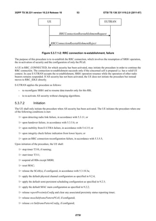
5.3.7.5 Reception of the RRCConnectionReestablishment by the UE
NOTE: Prior to this, lower layer signalling is used to allocate a C-RNTI. For further details see TS 36.321 [6];
The UE shall:
1> stop timer T301;
1> consider the current cell to be the PCell;
1> re-establish PDCP for SRB1;
1> re-establish RLC for SRB1;
1> perform the radio resource configuration procedure in accordance with the received
radioResourceConfigDedicated and as specified in 5.3.10;
1> resume SRB1;
1> update the KeNB key based on the KASME key to which the current KeNB is associated, using the
nextHopChainingCount value indicated in the RRCConnectionReestablishment message, as specified in TS
33.401 [32];
1> store the nextHopChainingCount value;
1> derive the KRRCint key associated with the previously configured integrity algorithm, as specified in TS 33.401
[32];
1> derive the KRRCenc key and the KUPenc key associated with the previously configured ciphering algorithm, as
specified in TS 33.401 [32];
1> if connected as an RN:
2> derive the KUPint key associated with the previously configured integrity algorithm, as specified in TS 33.401
[32];
1> configure lower layers to activate integrity protection using the previously configured algorithm and the KRRCint
key immediately, i.e., integrity protection shall be applied to all subsequent messages received and sent by the
UE, including the message used to indicate the successful completion of the procedure;
1> if connected as an RN:
2> configure lower layers to apply integrity protection using the previously configured algorithm and the KUPint
key, for subsequently resumed or subsequently established DRBs that are configured to apply integrity
protection, if any;
1> configure lower layers to apply ciphering using the previously configured algorithm, the KRRCenc key and the
KUPenc key immediately, i.e., ciphering shall be applied to all subsequent messages received and sent by the UE,
including the message used to indicate the successful completion of the procedure;
1> set the content of RRCConnectionReestablishmentComplete message as follows:
2> if the UE has radio link failure or handover failure information available in VarRLF-Report and plmn-Identity
stored in VarRLF-Report is equal to the RPLMN:
3> include the rlf-InfoAvailable;
2> if the UE has logged measurements available for E-UTRA and plmn-Identity stored in VarLogMeasReport is
equal to the RPLMN:
3> include the logMeasAvailable;
1> perform the measurement related actions as specified in 5.5.6.1;
ETSI](https://image.slidesharecdn.com/ts136331v100200p-111014005410-phpapp02/85/Ts-136331v100200p-56-320.jpg)
![3GPP TS 36.331 version 10.2.0 Release 10 56 ETSI TS 136 331 V10.2.0 (2011-07)
1> perform the measurement identity autonomous removal as specified in 5.5.2.2a;
1> submit the RRCConnectionReestablishmentComplete message to lower layers for transmission, upon which the
procedure ends;
5.3.7.6 T311 expiry
Upon T311 expiry, the UE shall:
1> perform the actions upon leaving RRC_CONNECTED as specified in 5.3.12, with release cause 'RRC
connection failure';
5.3.7.7 T301 expiry or selected cell no longer suitable
The UE shall:
1> if timer T301 expires; or
1> if the selected cell becomes no longer suitable according to the cell selection criteria as specified in TS 36.304
[4]:
2> perform the actions upon leaving RRC_CONNECTED as specified in 5.3.12, with release cause 'RRC
connection failure';
5.3.7.8 Reception of RRCConnectionReestablishmentReject by the UE
Upon receiving the RRCConnectionReestablishmentReject message, the UE shall:
1> perform the actions upon leaving RRC_CONNECTED as specified in 5.3.12, with release cause 'RRC
connection failure';
5.3.8 RRC connection release
5.3.8.1 General
UE EUTRAN
RRCConnectionRelease
Figure 5.3.8.1-1: RRC connection release, successful
The purpose of this procedure is to release the RRC connection, which includes the release of the established radio
bearers as well as all radio resources.
5.3.8.2 Initiation
E-UTRAN initiates the RRC connection release procedure to a UE in RRC_CONNECTED.
5.3.8.3 Reception of the RRCConnectionRelease by the UE
The UE shall:
1> delay the following actions defined in this sub-clause 60 ms from the moment the RRCConnectionRelease
message was received or optionally when lower layers indicate that the receipt of the RRCConnectionRelease
message has been successfully acknowledged, whichever is earlier;
1> if the RRCConnectionRelease message includes the idleModeMobilityControlInfo:
ETSI](https://image.slidesharecdn.com/ts136331v100200p-111014005410-phpapp02/85/Ts-136331v100200p-57-320.jpg)
![3GPP TS 36.331 version 10.2.0 Release 10 57 ETSI TS 136 331 V10.2.0 (2011-07)
2> store the cell reselection priority information provided by the idleModeMobilityControlInfo;
2> if the t320 is included:
3> start timer T320, with the timer value set according to the value of t320;
1> else:
2> apply the cell reselection priority information broadcast in the system information;
1> if the releaseCause received in the RRCConnectionRelease message indicates loadBalancingTAURequired:
2> perform the actions upon leaving RRC_CONNECTED as specified in 5.3.12, with release cause 'load
balancing TAU required';
1> else if the releaseCause received in the RRCConnectionRelease message indicates cs-FallbackHighPriority:
2> perform the actions upon leaving RRC_CONNECTED as specified in 5.3.12, with release cause 'CS Fallback
High Priority';
1> else:
2> if the extendedWaitTime is present and the UE supports delay tolerant access:
3> forward the extendedWaitTime to upper layers;
2> perform the actions upon leaving RRC_CONNECTED as specified in 5.3.12, with release cause other';
5.3.8.4 T320 expiry
The UE shall:
1> if T320 expires:
2> if stored, discard the cell reselection priority information provided by the idleModeMobilityControlInfo or
inherited from another RAT;
2> apply the cell reselection priority information broadcast in the system information;
5.3.9 RRC connection release requested by upper layers
5.3.9.1 General
The purpose of this procedure is to release the RRC connection. Access to the current PCell may be barred as a result of
this procedure.
NOTE: Upper layers invoke the procedure, e.g. upon determining that the network has failed an authentication
check, see TS 24.301 [35].
5.3.9.2 Initiation
The UE initiates the procedure when upper layers request the release of the RRC connection. The UE shall not initiate
the procedure for power saving purposes.
The UE shall:
1> if the upper layers indicate barring of the PCell:
2> treat the PCell used prior to entering RRC_IDLE as barred according to TS 36.304 [4];
1> perform the actions upon leaving RRC_CONNECTED as specified in 5.3.12, with release cause 'other';
ETSI](https://image.slidesharecdn.com/ts136331v100200p-111014005410-phpapp02/85/Ts-136331v100200p-58-320.jpg)
![3GPP TS 36.331 version 10.2.0 Release 10 63 ETSI TS 136 331 V10.2.0 (2011-07)
2> if AS security has not been activated:
3> perform the actions upon leaving RRC_CONNECTED as specified in 5.3.12, with release cause 'other';
2> else:
3> initiate the connection re-establishment procedure as specified in 5.3.7;
The UE may discard the radio link failure information, i.e. release the UE variable VarRLF-Report 48 hours after the
radio link failure is detected.
5.3.12 UE actions upon leaving RRC_CONNECTED
Upon leaving RRC_CONNECTED, the UE shall:
1> reset MAC;
1> stop all timers that are running except T320 and T330;
1> release all radio resources, including release of the RLC entity, the MAC configuration and the associated PDCP
entity for all established RBs;
1> indicate the release of the RRC connection to upper layers together with the release cause;
1> if leaving RRC_CONNECTED was triggered neither by reception of the MobilityFromEUTRACommand
message nor by selecting an inter-RAT cell while T311 was running:
2> enter RRC_IDLE and perform procedures as specified in TS 36.304 [4, 5.2.7];
5.3.13 UE actions upon PUCCH/ SRS release request
Upon receiving a PUCCH/ SRS release request from lower layers, the UE shall:
1> apply the default physical channel configuration for CQI-ReportConfig and cqi-Mask if configured as specified
in 9.2.4;
1> apply the default physical channel configuration for soundingRS-UL-ConfigDedicated as specified in 9.2.4;
1> apply the default physical channel configuration for schedulingRequestConfig as specified in 9.2.4;
NOTE: Upon PUCCH/ SRS release request, the UE does not modify the soundingRS-UL-
ConfigDedicatedAperiodic i.e. it does not apply the default for this field (release).
5.3.14 Proximity indication
5.3.14.1 General
UE EUTRAN
RRC connection reconfiguration
ProximityIndication
Figure 5.3.14.1-1: Proximity indication
ETSI](https://image.slidesharecdn.com/ts136331v100200p-111014005410-phpapp02/85/Ts-136331v100200p-64-320.jpg)
![3GPP TS 36.331 version 10.2.0 Release 10 64 ETSI TS 136 331 V10.2.0 (2011-07)
The purpose of this procedure is to indicate that the UE is entering or leaving the proximity of one or more cells whose
CSG IDs are in the UEs CSG whitelist. The detection of proximity is based on an autonomous search function as
defined in TS 36.304 [4].
5.3.14.2 Initiation
A UE in RRC_CONNECTED shall:
1> if the UE enters the proximity of one or more cell(s), whose CSG IDs are in the UEs CSG whitelist, on an E-
UTRA frequency while proximity indication is enabled for such E-UTRA cells; or
1> if the UE enters the proximity of one or more cell(s), whose CSG IDs are in the UEs CSG whitelist, on an UTRA
frequency while proximity indication is enabled for such UTRA cells; or
1> if the UE leaves the proximity of all cell(s), whose CSG IDs are in the UEs CSG whitelist, on an E-UTRA
frequency while proximity indication is enabled for such E-UTRA cells; or
1> if the UE leaves the proximity of all cell(s), whose CSG IDs are in the UEs CSG whitelist, on an UTRA
frequency while proximity indication is enabled for such UTRA cells:
2> if the UE has previously not transmitted a ProximityIndication for the RAT and frequency during the current
RRC connection, or if more than 5 s has elapsed since the UE has last transmitted a ProximityIndication
(either entering or leaving) for the RAT and frequency:
3> initiate transmission of the ProximityIndication message in accordance with 5.3.14.3;
NOTE: In the conditions above, "if the UE enters the proximity of one or more cells whose CSG IDs are in the
CSG whitelist" includes the case of already being in the proximity of such cell(s) at the time proximity
indication for the corresponding RAT is enabled.
5.3.14.3 Actions related to transmission of ProximityIndication message
The UE shall set the contents of ProximityIndication message as follows:
1> if the UE applies the procedure to report entering the proximity of cell(s) whose CSG IDs are in the UEs CSG
whitelist:
2> set type to entering;
1> else if the UE applies the procedure to report leaving the proximity of cell(s) whose CSG IDs are in the UEs
CSG whitelist:
2> set type to leaving;
1> if the proximity indication was triggered for one or more cell(s), whose CSG IDs are in the UEs CSG whitelist,
on an E-UTRA frequency:
2> set the carrierFreq to eutra with the value set to the E-ARFCN value of the E-UTRA cell(s) for which
proximity indication was triggered;
1> else if the proximity indication was triggered for one or more cell(s), whose CSG IDs are in the UEs CSG
whitelist, on a UTRA frequency:
2> set the carrierFreq to utra with the value set to the ARFCN value of the UTRA cell(s) for which proximity
indication was triggered;
The UE shall submit the ProximityIndication message to lower layers for transmission.
ETSI](https://image.slidesharecdn.com/ts136331v100200p-111014005410-phpapp02/85/Ts-136331v100200p-65-320.jpg)
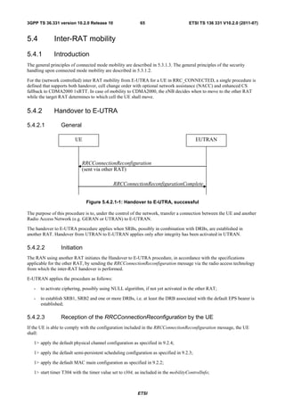
![3GPP TS 36.331 version 10.2.0 Release 10 66 ETSI TS 136 331 V10.2.0 (2011-07)
1> consider the target PCell to be one on the frequency indicated by the carrierFreq with a physical cell identity
indicated by the targetPhysCellId;
1> start synchronising to the DL of the target PCell;
1> set the C-RNTI to the value of the newUE-Identity;
1> for the target PCell, apply the downlink bandwidth indicated by the dl-Bandwidth;
1> for the target PCell, apply the uplink bandwidth indicated by (the absence or presence of) the ul-Bandwidth;
1> configure lower layers in accordance with the received radioResourceConfigCommon;
1> configure lower layers in accordance with any additional fields, not covered in the previous, if included in the
received mobilityControlInfo;
1> perform the radio resource configuration procedure as specified in 5.3.10;
1> forward the nas-SecurityParamToEUTRA to the upper layers;
1> derive the KeNB key, as specified in TS 33.401 [32];
1> derive the KRRCint key associated with the integrityProtAlgorithm, as specified in TS 33.401 [32];
1> derive the KRRCenc key and the KUPenc key associated with the cipheringAlgorithm, as specified in TS 33.401 [32];
1> configure lower layers to apply the indicated integrity protection algorithm and the KRRCint key immediately, i.e.
the indicated integrity protection configuration shall be applied to all subsequent messages received and sent by
the UE, including the message used to indicate the successful completion of the procedure;
1> configure lower layers to apply the indicated ciphering algorithm, the KRRCenc key and the KUPenc key
immediately, i.e. the indicated ciphering configuration shall be applied to all subsequent messages received and
sent by the UE, including the message used to indicate the successful completion of the procedure;
1> if the received RRCConnectionReconfiguration includes the sCellToAddModList:
2> perform SCell addition as specified in 5.3.10.3b;
1> if the RRCConnectionReconfiguration message includes the measConfig:
2> perform the measurement configuration procedure as specified in 5.5.2;
1> perform the measurement identity autonomous removal as specified in 5.5.2.2a;
1> if the RRCConnectionReconfiguration message includes the reportProximityConfig:
2> perform the proximity indication configuration in accordance with the received reportProximityConfig;
1> set the content of RRCConnectionReconfigurationComplete message as follows:
2> if the UE has radio link failure or handover failure information available in VarRLF-Report and plmn-Identity
stored in VarRLF-Report is equal to the RPLMN:
3> include rlf-InfoAvailable;
2> if the UE has logged measurements available for E-UTRA and plmn-Identity stored in VarLogMeasReport is
equal to the RPLMN:
3> include the logMeasAvailable;
1> submit the RRCConnectionReconfigurationComplete message to lower layers for transmission using the new
configuration;
1> if the RRCConnectionReconfiguration message does not include rlf-TimersAndConstants set to setup:
2> use the default values specified in 9.2.5 for timer T310, T311 and constant N310, N311;
1> if MAC successfully completes the random access procedure:
ETSI](https://image.slidesharecdn.com/ts136331v100200p-111014005410-phpapp02/85/Ts-136331v100200p-67-320.jpg)
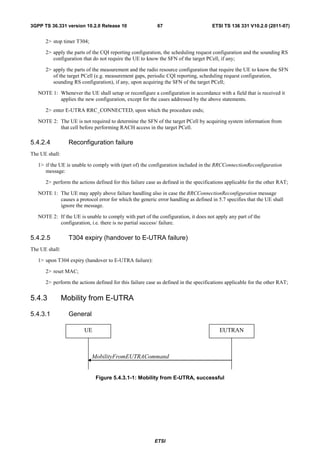
![3GPP TS 36.331 version 10.2.0 Release 10 68 ETSI TS 136 331 V10.2.0 (2011-07)
UE EUTRAN
MobilityFromEUTRACommand
RRC connection re-establishment
Figure 5.4.3.1-2: Mobility from E-UTRA, failure
The purpose of this procedure is to move a UE in RRC_CONNECTED to a cell using another Radio Access
Technology (RAT), e.g. GERAN, UTRA or CDMA2000 systems. The mobility from E-UTRA procedure covers the
following type of mobility:
- handover, i.e. the MobilityFromEUTRACommand message includes radio resources that have been allocated for
the UE in the target cell;
- cell change order, i.e. the MobilityFromEUTRACommand message may include information facilitating access
of and/ or connection establishment in the target cell, e.g. system information. Cell change order is applicable
only to GERAN; and
- enhanced CS fallback to CDMA2000 1xRTT, i.e. the MobilityFromEUTRACommand message includes radio
resources that have been allocated for the UE in the target cell. The enhanced CS fallback to CDMA2000 1xRTT
may be combined with concurrent handover or redirection to CDMA2000 HRPD.
NOTE: For the case of dual receiver/transmitter enhanced CS fallback to CDMA2000 1xRTT, the
DLInformationTransfer message is used instead of the MobilityFromEUTRACommand message (see TS
36.300 [9]).
5.4.3.2 Initiation
E-UTRAN initiates the mobility from E-UTRA procedure to a UE in RRC_CONNECTED, possibly in response to a
MeasurementReport message or in response to reception of CS fallback indication for the UE from MME, by sending a
MobilityFromEUTRACommand message. E-UTRAN applies the procedure as follows:
- the procedure is initiated only when AS-security has been activated, and SRB2 with at least one DRB are setup
and not suspended;
5.4.3.3 Reception of the MobilityFromEUTRACommand by the UE
The UE shall be able to receive a MobilityFromEUTRACommand message and perform a cell change order to GERAN,
even if no prior UE measurements have been performed on the target cell.
The UE shall:
1> stop timer T310, if running;
1> if the MobilityFromEUTRACommand message includes the purpose set to handover:
2> if the targetRAT-Type is set to utra or geran:
3> consider inter-RAT mobility as initiated towards the RAT indicated by the targetRAT-Type included in
the MobilityFromEUTRACommand message;
3> forward the nas-SecurityParamFromEUTRA to the upper layers;
3> access the target cell indicated in the inter-RAT message in accordance with the specifications of the
target RAT;
3> if the targetRAT-Type is set to geran:
ETSI](https://image.slidesharecdn.com/ts136331v100200p-111014005410-phpapp02/85/Ts-136331v100200p-69-320.jpg)
![3GPP TS 36.331 version 10.2.0 Release 10 69 ETSI TS 136 331 V10.2.0 (2011-07)
4> use the contents of systemInformation, if provided for PS Handover, as the system information to
begin access on the target GERAN cell;
NOTE 1: If there are DRBs for which no radio bearers are established in the target RAT as indicated in the
targetRAT-MessageContainer in the message, the E-UTRA RRC part of the UE does not indicate the
release of the concerned DRBs to the upper layers. Upper layers may derive which bearers are not
established from information received from the AS of the target RAT.
NOTE 2: In case of SR-VCC, the DRB to be replaced is specified in [61].
2> else if the targetRAT-Type is set to cdma2000-1XRTT or cdma2000-HRPD:
3> forward the targetRAT-Type and the targetRAT-MessageContainer to the CDMA2000 upper layers for
the UE to access the cell(s) indicated in the inter-RAT message in accordance with the specifications of
the CDMA2000 target-RAT;
1> else if the MobilityFromEUTRACommand message includes the purpose set to cellChangeOrder:
2> start timer T304 with the timer value set to t304, as included in the MobilityFromEUTRACommand message;
2> if the targetRAT-Type is set to geran:
3> if networkControlOrder is included in the MobilityFromEUTRACommand message:
4> apply the value as specified in TS 44.060 [36];
3> else:
4> acquire networkControlOrder and apply the value as specified in TS 44.060 [36];
3> use the contents of systemInformation, if provided, as the system information to begin access on the target
GERAN cell;
NOTE 3: The systemInformation is constructed in the same way as in 2G to 2G NACC, i.e. the PSI messages are
encoded as such, whereas the SI messages exclude 2 octets of headers, see TS 44.060[36].
2> establish the connection to the target cell indicated in the CellChangeOrder;
NOTE 4: The criteria for success or failure of the cell change order to GERAN are specified in TS 44.060[36].
1> if the MobilityFromEUTRACommand message includes the purpose set to e-CSFB:
2> if messageContCDMA2000-1XRTT is present:
3> forward the messageContCDMA2000-1XRTT to the CDMA2000 upper layers for the UE to access the
cell(s) indicated in the inter-RAT message in accordance with the specification of the target RAT;
2> if mobilityCDMA2000-HRPD is present and is set to handover:
3> forward the messageContCDMA2000-HRPD to the CDMA2000 upper layers for the UE to access the
cell(s) indicated in the inter-RAT message in accordance with the specification of the target RAT;
2> if mobilityCDMA2000-HRPD is present and is set to redirection:
3> forward the redirectedCarrierInfoCDMA2000-HRPD to the CDMA2000 upper layers;
NOTE 5: When the CDMA2000 upper layers in the UE receive both the messageContCDMA2000-1XRTT and
messageContCDMA2000-HRPD the UE performs concurrent access to both CDMA2000 1xRTT and
CDMA2000 HRPD RAT.
5.4.3.4 Successful completion of the mobility from E-UTRA
Upon successfully completing the handover, the cell change order or enhanced 1xRTT CS fallback, the UE shall:
1> perform the actions upon leaving RRC_CONNECTED as specified in 5.3.12, with release cause 'other';
ETSI](https://image.slidesharecdn.com/ts136331v100200p-111014005410-phpapp02/85/Ts-136331v100200p-70-320.jpg)
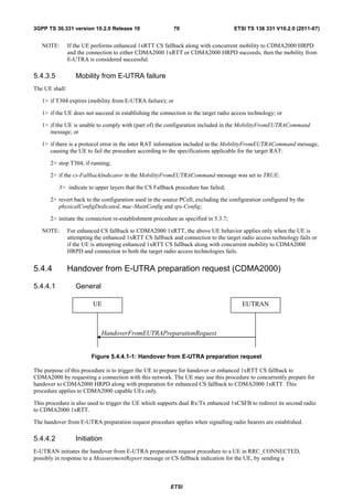
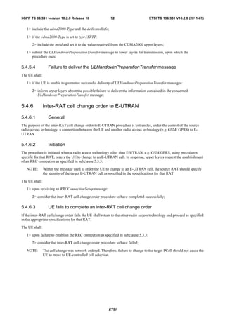
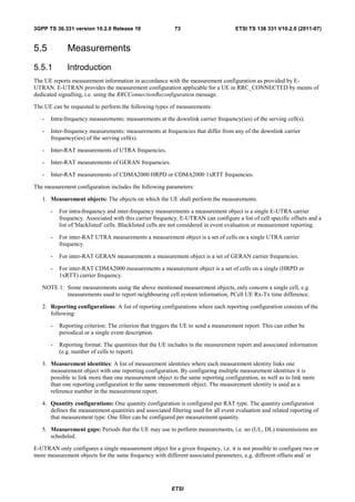
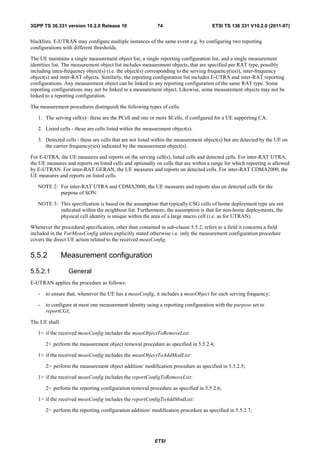
![3GPP TS 36.331 version 10.2.0 Release 10 76 ETSI TS 136 331 V10.2.0 (2011-07)
5.5.2.3 Measurement identity addition/ modification
E-UTRAN applies the procedure as follows:
- configure a measId only if the corresponding measurement object, the corresponding reporting configuration and
the corresponding quantity configuration, are configured;
The UE shall:
1> for each measId included in the received measIdToAddModList:
2> if an entry with the matching measId exists in the measIdList within the VarMeasConfig:
3> replace the entry with the value received for this measId;
2> else:
3> add a new entry for this measId within the VarMeasConfig ;
2> remove the measurement reporting entry for this measId from the VarMeasReportList, if included;
2> stop the periodical reporting timer or timer T321, whichever one is running, and reset the associated
information (e.g. timeToTrigger) for this measId;
2> if the triggerType is set to periodical and the purpose is set to reportCGI in the reportConfig associated with
this measId:
3> if the measObject associated with this measId concerns E-UTRA:
4> if the si-RequestForHO is included in the reportConfig associated with this measId:
5> start timer T321 with the timer value set to 150 ms for this measId;
4> else:
5> start timer T321 with the timer value set to 1 second for this measId;
3> else if the measObject associated with this measId concerns UTRA:
4> if the si-RequestForHO is included in the reportConfig associated with this measId:
5> start timer T321 with the timer value set to [1 second] for this measId;
4> else:
5> start timer T321 with the timer value set to 8 seconds for this measId;
3> else:
4> start timer T321 with the timer value set to 8 seconds for this measId;
5.5.2.4 Measurement object removal
The UE shall:
1> for each measObjectId included in the received measObjectToRemoveList that is part of the current UE
configuration in VarMeasConfig:
2> remove the entry with the matching measObjectId from the measObjectList within the VarMeasConfig;
2> remove all measId associated with this measObjectId from the measIdList within the VarMeasConfig, if any;
2> if a measId is removed from the measIdList:
3> remove the measurement reporting entry for this measId from the VarMeasReportList, if included;
ETSI](https://image.slidesharecdn.com/ts136331v100200p-111014005410-phpapp02/85/Ts-136331v100200p-77-320.jpg)
![3GPP TS 36.331 version 10.2.0 Release 10 79 ETSI TS 136 331 V10.2.0 (2011-07)
1> if measGapConfig is set to setup:
2> if a measurement gap configuration is already setup, release the measurement gap configuration;
2> setup the measurement gap configuration indicated by the measGapConfig in accordance with the received
gapOffset, i.e., each gap starts at an SFN and subframe meeting the following condition:
SFN mod T = FLOOR(gapOffset/10);
subframe = gapOffset mod 10;
with T = MGRP/10 as defined in TS 36.133 [16];
1> else:
2> release the measurement gap configuration;
5.5.3 Performing measurements
5.5.3.1 General
For all measurements the UE applies the layer 3 filtering as specified in 5.5.3.2, before using the measured results for
evaluation of reporting criteria or for measurement reporting.
The UE shall:
1> whenever the UE has a measConfig, perform RSRP and RSRQ measurements for each serving cell, applying for
the PCell the time domain measurement resource restriction in accordance with measSubframePatternPCell, if
configured;
1> for each measId included in the measIdList within VarMeasConfig:
2> if the purpose for the associated reportConfig is set to reportCGI:
3> if si-RequestForHO is configured for the associated reportConfig:
4> perform the corresponding measurements on the frequency and RAT indicated in the associated
measObject using autonomous gaps as necessary;
3> else:
4> perform the corresponding measurements on the frequency and RAT indicated in the associated
measObject using available idle periods or using autonomous gaps as necessary;
NOTE 1: If autonomous gaps are used to perform measurements, the UE is allowed to temporarily abort
communication with all serving cell(s), i.e. create autonomous gaps to perform the corresponding
measurements within the limits specified in TS 36.133 [16]. Otherwise, the UE only supports the
measurements with the purpose set to reportCGI only if E-UTRAN has provided sufficient idle periods.
3> try to acquire the global cell identity of the cell indicated by the cellForWhichToReportCGI in the
associated measObject by acquiring the relevant system information from the concerned cell;
3> if the cell indicated by the cellForWhichToReportCGI included in the associated measObject is an E-
UTRAN cell:
4> try to acquire the CSG identity, if the CSG identity is broadcast in the concerned cell;
4> try to acquire the trackingAreaCode in the concerned cell;
4> if si-RequestForHO is not configured for the associated reportConfig:
5> try to acquire the list of additional PLMN Identities, as included in the plmn-IdentityList, if
multiple PLMN identities are broadcast in the concerned cell;
NOTE 2: The 'primary' PLMN is part of the global cell identity.
ETSI](https://image.slidesharecdn.com/ts136331v100200p-111014005410-phpapp02/85/Ts-136331v100200p-80-320.jpg)
![3GPP TS 36.331 version 10.2.0 Release 10 80 ETSI TS 136 331 V10.2.0 (2011-07)
3> if the cell indicated by the cellForWhichToReportCGI included in the associated measObject is a UTRAN
cell:
4> try to acquire the LAC, the RAC and the list of additional PLMN Identities, if multiple PLMN
identities are broadcast in the concerned cell;
4> try to acquire the CSG identity, if the CSG identity is broadcast in the concerned cell;
3> if the cell indicated by the cellForWhichToReportCGI included in the associated measObject is a GERAN
cell:
4> try to acquire the RAC in the concerned cell;
3> if the cell indicated by the cellForWhichToReportCGI included in the associated measObject is a
CDMA2000 cell and the cdma2000-Type included in the measObject is typeHRPD:
4> try to acquire the Sector ID in the concerned cell;
3> if the cell indicated by the cellForWhichToReportCGI included in the associated measObject is a
CDMA2000 cell and the cdma2000-Type included in the measObject is type1XRTT:
4> try to acquire the BASE ID, SID and NID in the concerned cell;
2> else:
3> if a measurement gap configuration is setup; or
3> if the UE does not require measurement gaps to perform the concerned measurements:
4> if s-Measure is not configured; or
4> if s-Measure is configured and the PCell RSRP, after layer 3 filtering, is lower than this value:
5> perform the corresponding measurements of neighbouring cells on the frequencies and RATs
indicated in the concerned measObject, applying for neighbouring cells on the primary frequency
the time domain measurement resource restriction in accordance with
measSubframePatternConfigNeigh, if configured in the concerned measObject;
4> if the ue-RxTxTimeDiffPeriodical is configured in the associated reportConfig:
5> perform the UE Rx–Tx time difference measurements on the PCell;
2> perform the evaluation of reporting criteria as specified in 5.5.4;
NOTE 3: The s-Measure defines when the UE is required to perform measurements. The UE is however allowed to
perform measurements also when the PCell RSRP exceeds s-Measure, e.g., to measure cells broadcasting
a CSG identity following use of the autonomous search function as defined in TS 36.304 [4].
5.5.3.2 Layer 3 filtering
The UE shall:
1> for each measurement quantity that the UE performs measurements according to 5.5.3.1:
NOTE 1: This does not include quantities configured solely for UE Rx-Tx time difference measurements i.e. for
those type of measurements the UE ignores the triggerQuantity and reportQuantity.
2> filter the measured result, before using for evaluation of reporting criteria or for measurement reporting, by
the following formula:
Fn = (1 − a ) ⋅ Fn−1 + a ⋅ M n
where
Mn is the latest received measurement result from the physical layer;
ETSI](https://image.slidesharecdn.com/ts136331v100200p-111014005410-phpapp02/85/Ts-136331v100200p-81-320.jpg)
![3GPP TS 36.331 version 10.2.0 Release 10 81 ETSI TS 136 331 V10.2.0 (2011-07)
Fn is the updated filtered measurement result, that is used for evaluation of reporting criteria or for
measurement reporting;
Fn-1 is the old filtered measurement result, where F0 is set to M1 when the first measurement result from
the physical layer is received; and
a = 1/2(k/4), where k is the filterCoefficent for the corresponding measurement quantity received by the
quantityConfig;
2> adapt the filter such that the time characteristics of the filter are preserved at different input rates, observing
that the filterCoefficent k assumes a sample rate equal to 200 ms;
NOTE 2: If k is set to 0, no layer 3 filtering is applicable.
NOTE 3: The filtering is performed in the same domain as used for evaluation of reporting criteria or for
measurement reporting, i.e., logarithmic filtering for logarithmic measurements.
NOTE 4: The filter input rate is implementation dependent, to fulfil the performance requirements set in [16]. For
further details about the physical layer measurements, see TS 36.133 [16].
5.5.4 Measurement report triggering
5.5.4.1 General
The UE shall:
1> for each measId included in the measIdList within VarMeasConfig:
2> if the corresponding reportConfig includes a purpose set to reportStrongestCellsForSON:
3> consider any neighbouring cell detected on the associated frequency to be applicable;
2> else if the corresponding reportConfig includes a purpose set to reportCGI:
3> consider any neighbouring cell detected on the associated frequency/ set of frequencies (GERAN) which
has a physical cell identity matching the value of the cellForWhichToReportCGI included in the
corresponding measObject within the VarMeasConfig to be applicable;
2> else:
3> if the corresponding measObject concerns E-UTRA:
4> if the ue-RxTxTimeDiffPeriodical is configured in the corresponding reportConfig:
5> consider only the PCell to be applicable;
4> else if the eventA1 or eventA2 is configured in the corresponding reportConfig:
5> consider only the serving cell to be applicable;
4> else:
5> consider any neighbouring cell detected on the associated frequency to be applicable when the
concerned cell is not included in the blackCellsToAddModList defined within the VarMeasConfig
for this measId;
5> for events involving a serving cell on one frequency and neighbours on another frequency,
consider the serving cell on the other frequency as a neighbouring cell;
3> else if the corresponding measObject concerns UTRA or CDMA2000:
4> consider a neighbouring cell on the associated frequency to be applicable when the concerned cell is
included in the cellsToAddModList defined within the VarMeasConfig for this measId (i.e. the cell is
included in the white-list);
ETSI](https://image.slidesharecdn.com/ts136331v100200p-111014005410-phpapp02/85/Ts-136331v100200p-82-320.jpg)
![3GPP TS 36.331 version 10.2.0 Release 10 83 ETSI TS 136 331 V10.2.0 (2011-07)
NOTE 1: If the purpose is set to reportStrongestCells, the UE initiates a first measurement report immediately after
the quantity to be reported becomes available for at least either all serving cells or one of the applicable
cells. If the purpose is set to reportStrongestCellsForSON, the UE initiates a first measurement report
when it has determined the strongest cells on the associated frequency.
2> upon expiry of the periodical reporting timer for this measId:
3> initiate the measurement reporting procedure, as specified in 5.5.5;
2> if the purpose is included and set to reportCGI and if the UE acquired the information needed to set all fields
of cgi-Info for the requested cell:
3> include a measurement reporting entry within the VarMeasReportList for this measId;
3> set the numberOfReportsSent defined within the VarMeasReportList for this measId to 0;
3> stop timer T321;
3> initiate the measurement reporting procedure, as specified in 5.5.5;
2> upon expiry of the T321 for this measId:
3> include a measurement reporting entry within the VarMeasReportList for this measId;
3> set the numberOfReportsSent defined within the VarMeasReportList for this measId to 0;
3> initiate the measurement reporting procedure, as specified in 5.5.5;
NOTE 2: The UE does not stop the periodical reporting with triggerType set to event or to periodical while the
corresponding measurement is not performed due to the PCell RSRP being equal to or better than s-
Measure or due to the measurement gap not being setup.
NOTE 3: If the UE is configured with DRX, the UE may delay the measurement reporting for event triggered and
periodical triggered measurements until the Active Time, which is defined in TS 36.321 [6].
5.5.4.2 Event A1 (Serving becomes better than threshold)
The UE shall:
1> consider the entering condition for this event to be satisfied when condition A1-1, as specified below, is fulfilled;
1> consider the leaving condition for this event to be satisfied when condition A1-2, as specified below, is fulfilled;
1> for this measurement, consider the primary or secondary cell that is configured on the frequency indicated in the
associated measObjectEUTRA to be the serving cell;
Inequality A1-1 (Entering condition)
Ms − Hys > Thresh
Inequality A1-2 (Leaving condition)
Ms + Hys < Thresh
The variables in the formula are defined as follows:
Ms is the measurement result of the serving cell, not taking into account any offsets.
Hys is the hysteresis parameter for this event (i.e. hysteresis as defined within reportConfigEUTRA for this event).
Thresh is the threshold parameter for this event (i.e. a1-Threshold as defined within reportConfigEUTRA for this
event).
Ms is expressed in dBm in case of RSRP, or in dB in case of RSRQ.
Hys is expressed in dB.
ETSI](https://image.slidesharecdn.com/ts136331v100200p-111014005410-phpapp02/85/Ts-136331v100200p-84-320.jpg)
![3GPP TS 36.331 version 10.2.0 Release 10 89 ETSI TS 136 331 V10.2.0 (2011-07)
1> set the measResultServFreqList to include for each SCell that is configured, if any, within measResultSCell the
quantities of the concerned SCell;
1> if the reportConfig associated with the measId that triggered the measurement reporting includes
reportAddNeighMeas:
2> for each serving frequency for which measObjectId is referenced in the measIdList, other than the frequency
corresponding with the measId that triggered the measurement reporting:
3> set the measResultServFreqList to include within measResultBestNeighCell the physCellId and the
quantities of the best non-serving cell, based on RSRP, on the concerned serving frequency;
1> if there is at least one applicable neighbouring cell to report:
2> set the measResultNeighCells to include the best neighbouring cells up to maxReportCells in accordance with
the following:
3> if the triggerType is set to event:
4> include the cells included in the cellsTriggeredList as defined within the VarMeasReportList for this
measId;
3> else:
4> include the applicable cells for which the new measurement results became available since the last
periodical reporting or since the measurement was initiated or reset;
NOTE: The reliability of the report (i.e. the certainty it contains the strongest cells on the concerned frequency)
depends on the measurement configuration i.e. the reportInterval. The related performance requirements
are specified in TS 36.133 [16].
3> for each cell that is included in the measResultNeighCells, include the physCellId;
3> if the triggerType is set to event; or the purpose is set to reportStrongestCells or to
reportStrongestCellsForSON:
4> for each included cell, include the layer 3 filtered measured results in accordance with the
reportConfig for this measId, ordered as follows:
5> if the measObject associated with this measId concerns E-UTRA:
6> set the measResult to include the quantity(ies) indicated in the reportQuantity within the
concerned reportConfig in order of decreasing triggerQuantity, i.e. the best cell is included
first;
5> if the measObject associated with this measId concerns UTRA FDD and if ReportConfigInterRAT
includes the reportQuantityUTRA-FDD:
6> set the measResult to include the quantities indicated by the reportQuantityUTRA-FDD in
order of decreasing measQuantityUTRA-FDD within the quantityConfig, i.e. the best cell is
included first;
5> if the measObject associated with this measId concerns UTRA FDD and if ReportConfigInterRAT
does not include the reportQuantityUTRA-FDD; or
5> if the measObject associated with this measId concerns UTRA TDD, GERAN or CDMA2000:
6> set the measResult to the quantity as configured for the concerned RAT within the
quantityConfig in order of either decreasing quantity for UTRA and GERAN or increasing
quantity for CDMA2000 pilotStrength, i.e. the best cell is included first;
3> else if the purpose is set to reportCGI:
4> if the mandatory present fields of the cgi-Info for the cell indicated by the cellForWhichToReportCGI
in the associated measObject have been obtained:
5> if the cell broadcasts a CSG identity:
ETSI](https://image.slidesharecdn.com/ts136331v100200p-111014005410-phpapp02/85/Ts-136331v100200p-90-320.jpg)
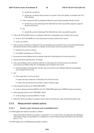
![3GPP TS 36.331 version 10.2.0 Release 10 91 ETSI TS 136 331 V10.2.0 (2011-07)
- when performing the connection re-establishment procedure, as specified in 5.3.7, ensure that a measObjectId
corresponding each target serving frequency is configured as a result of the procedure described in this sub-
clause and the subsequent connection reconfiguration procedure immediately following the re-establishment
procedure;
The UE shall:
1> for each measId included in the measIdList within VarMeasConfig:
2> if the triggerType is set to periodical:
3> remove this measId from the measIdList within VarMeasConfig:
1> if the procedure was triggered due to a handover or successful re-establishment and the procedure involves a
change of primary frequency, update the measId values in the measIdList within VarMeasConfig as follows:
2> if a measObjectId value corresponding to the target primary frequency exists in the measObjectList within
VarMeasConfig:
3> for each measId value in the measIdList:
4> if the measId value is linked to the measObjectId value corresponding to the source primary
frequency:
5> link this measId value to the measObjectId value corresponding to the target primary frequency;
4> else if the measId value is linked to the measObjectId value corresponding to the target primary
frequency:
5> link this measId value to the measObjectId value corresponding to the source primary frequency;
2> else:
3> remove all measId values that are linked to the measObjectId value corresponding to the source primary
frequency;
1> remove all measurement reporting entries within VarMeasReportList;
1> stop the periodical reporting timer or timer T321, whichever one is running, as well as associated information
(e.g. timeToTrigger) for all measId;
1> release the measurement gaps, if activated;
NOTE: If the UE requires measurement gaps to perform inter-frequency or inter-RAT measurements, the UE
resumes the inter-frequency and inter-RAT measurements after the E-UTRAN has setup the measurement
gaps.
5.5.6.2 Speed dependant scaling of measurement related parameters
The UE shall adjust the value of the following parameter configured by the E-UTRAN depending on the UE speed:
timeToTrigger. The UE shall apply 3 different levels, which are selected as follows:
The UE shall:
1> perform mobility state detection using the mobility state detection as specified in TS 36.304 [4] with the
following modifications:
2> counting handovers instead of cell reselections;
2> applying the parameter applicable for RRC_CONNECTED as included in speedStatePars within
VarMeasConfig;
1> if high mobility state is detected:
2> use the timeToTrigger value multiplied by sf-High within VarMeasConfig;
1> else if medium mobility state is detected:
ETSI](https://image.slidesharecdn.com/ts136331v100200p-111014005410-phpapp02/85/Ts-136331v100200p-92-320.jpg)
![3GPP TS 36.331 version 10.2.0 Release 10 92 ETSI TS 136 331 V10.2.0 (2011-07)
2> use the timeToTrigger value multiplied by sf-Medium within VarMeasConfig;
1> else
2> no scaling is applied;
5.5.7 Inter-frequency RSTD measurement indication
5.5.7.1 General
UE EUTRAN
InterFreqRSTDMeasurementIndication
Figure 5.5.7.1-1: Inter-frequency RSTD measurement indication
The purpose of this procedure is to indicate to the network that the UE is going to start/stop OTDOA inter-frequency
RSTD measurements which require measurement gaps as specified in [16, 8.1.2.6].
NOTE: It is a network decision to configure the measurement gap.
5.5.7.2 Initiation
The UE shall:
1> if and only if upper layers indicate to start performing inter-frequency RSTD measurements; and the UE requires
measurement gaps for these measurements while measurement gaps are either not configured or not sufficient:
2> initiate the procedure to indicate start;
NOTE 1: The UE verifies the measurement gap situation only upon receiving the indication from upper layers. If at
this point in time sufficient gaps are available, the UE does not initiate the procedure. Also if at a later
point in time the measurement gaps become insufficient, the UE does not initiate the procedure unless it
receives a new indication from upper layers.
1> if and only if upper layers indicate to stop performing inter-frequency RSTD measurements:
2> initiate the procedure to indicate stop;
NOTE 2: The UE may initiate the procedure to indicate stop even if it did not previously initiate the procedure to
indicate start.
5.5.7.3 Actions related to transmission of InterFreqRSTDMeasurementIndication
message
The UE shall set the contents of InterFreqRSTDMeasurementIndication message as follows:
1> set the rstd-InterFreqIndication as follows:
2> if the procedure is initiated to indicate start of inter-frequency RSTD measurements:
3> set the rstd-InterFreqInfoList according to the information received from upper layers;
2> else if the procedure is initiated to indicate stop of inter-frequency RSTD measurements:
3> set the rstd-InterFreqIndication to the value stop;
ETSI](https://image.slidesharecdn.com/ts136331v100200p-111014005410-phpapp02/85/Ts-136331v100200p-93-320.jpg)
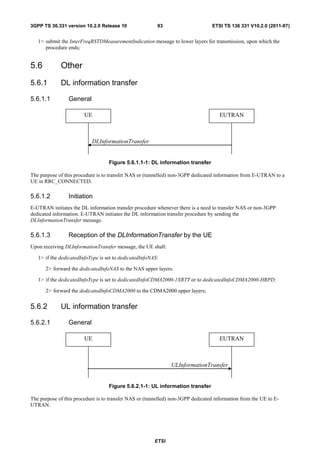
![3GPP TS 36.331 version 10.2.0 Release 10 94 ETSI TS 136 331 V10.2.0 (2011-07)
5.6.2.2 Initiation
A UE in RRC_CONNECTED initiates the UL information transfer procedure whenever there is a need to transfer NAS
or non-3GPP dedicated information, except at RRC connection establishment in which case the NAS information is
piggybacked to the RRCConnectionSetupComplete message. The UE initiates the UL information transfer procedure by
sending the ULInformationTransfer message. When CDMA2000 information has to be transferred, the UE shall initiate
the procedure only if SRB2 is established.
5.6.2.3 Actions related to transmission of ULInformationTransfer message
The UE shall set the contents of the ULInformationTransfer message as follows:
1> if there is a need to transfer NAS information:
2> set the dedicatedInfoType to include the dedicatedInfoNAS;
1> if there is a need to transfer CDMA2000 1XRTT information:
2> set the dedicatedInfoType to include the dedicatedInfoCDMA2000-1XRTT;
1> if there is a need to transfer CDMA2000 HRPD information:
2> set the dedicatedInfoType to include the dedicatedInfoCDMA2000-HRPD;
1> submit the ULInformationTransfer message to lower layers for transmission, upon which the procedure ends;
5.6.2.4 Failure to deliver ULInformationTransfer message
The UE shall:
1> if mobility (i.e. handover, RRC connection re-establishment) occurs before the successful delivery of
ULInformationTransfer messages has been confirmed by lower layers:
2> inform upper layers about the possible failure to deliver the information contained in the concerned
ULInformationTransfer messages;
5.6.3 UE capability transfer
5.6.3.1 General
UE EUTRAN
UECapabilityEnquiry
UECapabilityInformation
Figure 5.6.3.1-1: UE capability transfer
The purpose of this procedure is to transfer UE radio access capability information from the UE to E-UTRAN.
If the UE has changed its E-UTRAN radio access capabilities, the UE shall request higher layers to initiate the
necessary NAS procedures (see TS 23.401 [41]) that would result in the update of UE radio access capabilities using a
new RRC connection.
NOTE: Change of the UE's GERAN UE radio capabilities in RRC_IDLE is supported by use of Tracking Area
Update.
ETSI](https://image.slidesharecdn.com/ts136331v100200p-111014005410-phpapp02/85/Ts-136331v100200p-95-320.jpg)
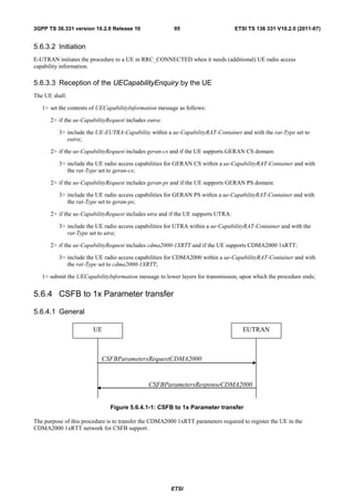
![3GPP TS 36.331 version 10.2.0 Release 10 96 ETSI TS 136 331 V10.2.0 (2011-07)
5.6.4.2 Initiation
A UE in RRC_CONNECTED initiates the CSFB to 1x Parameter transfer procedure upon request from the CDMA2000
upper layers. The UE initiates the CSFB to 1x Parameter transfer procedure by sending the
CSFBParametersRequestCDMA2000 message.
5.6.4.3 Actions related to transmission of CSFBParametersRequestCDMA2000 message
The UE shall:
1> submit the CSFBParametersRequestCDMA2000 message to lower layers for transmission using the current
configuration;
5.6.4.4 Reception of the CSFBParametersResponseCDMA2000 message
Upon reception of the CSFBParametersResponseCDMA2000 message, the UE shall:
1> forward the rand and the mobilityParameters to the CDMA2000 1xRTT upper layers;
5.6.5 UE Information
5.6.5.1 General
UE EUTRAN
UEInformationRequest
UEInformationResponse
Figure 5.6.5.1-1: UE information procedure
The UE information procedure is used by E-UTRAN to request the UE to report information.
5.6.5.2 Initiation
E-UTRAN initiates the procedure by sending the UEInformationRequest message.
5.6.5.3 Reception of the UEInformationRequest message
Upon receiving the UEInformationRequest message, the UE shall:
1> if rach-ReportReq is set to true, set the contents of the rach-Report in the UEInformationResponse message as
follows:
2> set the numberOfPreamblesSent to indicate the number of preambles sent by MAC for the last successfully
completed random access procedure;
2> if contention resolution was not successful as specified in TS 36.321 [6] for at least one of the transmitted
preambles for the last successfully completed random access procedure:
3> set the contentionDetected to true;
2> else:
3> set the contentionDetected to false;
ETSI](https://image.slidesharecdn.com/ts136331v100200p-111014005410-phpapp02/85/Ts-136331v100200p-97-320.jpg)
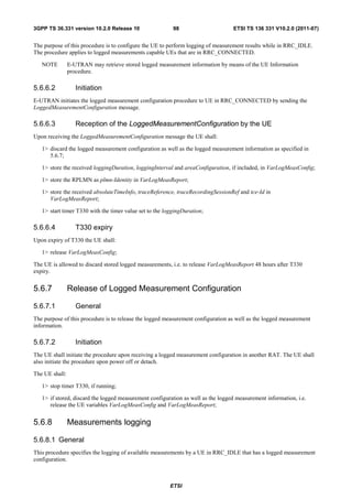
![3GPP TS 36.331 version 10.2.0 Release 10 99 ETSI TS 136 331 V10.2.0 (2011-07)
5.6.8.2 Initiation
While T330 is running, the UE shall:
1> perform the logging in accordance with the following:
2> if the UE is camping normally on an E-UTRA cell and the RPLMN of the UE is the same as the plmn-
Identity stored in VarLogMeasReport and, if the cell is part of the area indicated by areaConfiguration if
configured in VarLogMeasConfig:
3> perform the logging at regular time intervals, as defined by the loggingInterval in VarLogMeasConfig;
2> when adding a logged measurement entry in VarLogMeasReport, include the fields in accordance with the
following:
3> set the relativeTimeStamp to indicate the elapsed time since the moment at which the logged
measurement configuration was received;
3> if detailed location information became available during the last logging interval, set the content of the
locationInfo as follows:
4> include the locationCoordinates;
3> set the servCellIdentity to indicate global cell identity of the cell the UE is camping on;
3> set the measResultServCell to include the quantities of the cell the UE is camping on;
3> if available, set the measResultNeighCells, in order of decreasing ranking-criterion as used for cell re-
selection, to include neighbouring cell measurements that became available during the last logging
interval for at most the following number of neighbouring cells; 6 intra-frequency and 3 inter-frequency
neighbours per frequency as well as 3 inter-RAT neighbours, per frequency/ set of frequencies (GERAN)
per RAT;
NOTE: The UE includes the latest results of the available measurements as used for cell reselection evaluation,
which are performed in accordance with the performance requirements as specified in TS 36.133 [16].
2> when the memory reserved for the logged measurement information becomes full, stop timer T330 and
perform the same actions as performed upon expiry of T330, as specified in 5.6.6.4;
5.7 Generic error handling
5.7.1 General
The generic error handling defined in the subsequent sub-clauses applies unless explicitly specified otherwise e.g.
within the procedure specific error handling.
The UE shall consider a value as not comprehended when it is set:
- to an extended value that is not defined in the version of the transfer syntax supported by the UE.
- to a spare or reserved value unless the specification defines specific behaviour that the UE shall apply upon
receiving the concerned spare/ reserved value.
The UE shall consider a field as not comprehended when it is defined:
- as spare or reserved unless the specification defines specific behaviour that the UE shall apply upon receiving the
concerned spare/ reserved field.
5.7.2 ASN.1 violation or encoding error
The UE shall:
ETSI](https://image.slidesharecdn.com/ts136331v100200p-111014005410-phpapp02/85/Ts-136331v100200p-100-320.jpg)
![3GPP TS 36.331 version 10.2.0 Release 10 100 ETSI TS 136 331 V10.2.0 (2011-07)
1> when receiving an RRC message on the BCCH, PCCH, CCCH, or MCCH for which the abstract syntax is
invalid [13]:
2> ignore the message;
NOTE This section applies in case one or more fields is set to a value, other than a spare, reserved or extended
value, not defined in this version of the transfer syntax. E.g. in the case the UE receives value 12 for a
field defined as INTEGER (1..11). In cases like this, it may not be possible to reliably detect which field
is in the error hence the error handling is at the message level.
5.7.3 Field set to a not comprehended value
The UE shall, when receiving an RRC message on any logical channel:
1> if the message includes a field that has a value that the UE does not comprehend:
2> if a default value is defined for this field:
3> treat the message while using the default value defined for this field;
2> else if the concerned field is optional:
3> treat the message as if the field were absent and in accordance with the need code for absence of the
concerned field;
2> else:
3> treat the message as if the field were absent and in accordance with sub-clause 5.7.4;
5.7.4 Mandatory field missing
The UE shall:
1> if the message includes a field that is mandatory to include in the message (e.g. because conditions for
mandatory presence are fulfilled) and that field is absent or treated as absent:
2> if the RRC message was received on DCCH or CCCH:
3> ignore the message;
2> else:
3> if the field concerns a (sub-field of) an entry of a list (i.e. a SEQUENCE OF):
4> treat the list as if the entry including the missing or not comprehended field was not present;
3> else if the field concerns a sub-field of another field, referred to as the 'parent' field i.e. the field that is one
nesting level up compared to the erroneous field:
4> consider the 'parent' field to be set to a not comprehended value;
4> apply the generic error handling to the subsequent 'parent' field(s), until reaching the top nesting level
i.e. the message level;
3> else (field at message level):
4> ignore the message;
NOTE 1: The error handling defined in these sub-clauses implies that the UE ignores a message with the message
type or version set to a not comprehended value.
NOTE 2: The nested error handling for messages received on logical channels other than DCCH and CCCH applies
for errors in extensions also, even for errors that can be regarded as invalid E-UTRAN operation e.g. E-
UTRAN not observing conditional presence.
ETSI](https://image.slidesharecdn.com/ts136331v100200p-111014005410-phpapp02/85/Ts-136331v100200p-101-320.jpg)
![3GPP TS 36.331 version 10.2.0 Release 10 101 ETSI TS 136 331 V10.2.0 (2011-07)
The following ASN.1 further clarifies the levels applicable in case of nested error handling for errors in extension
fields.
-- /example/ ASN1START
-- Example with extension addition group
ItemInfoList ::= SEQUENCE (SIZE (1..max)) OF ItemInfo
ItemInfo ::= SEQUENCE {
itemIdentity INTEGER (1..max),
field1 Field1,
field2 Field2 OPTIONAL, -- Need ON
...
[[ field3-r9 Field3-r9 OPTIONAL, -- Cond Cond1
field4-r9 Field4-r9 OPTIONAL -- Need ON
]]
}
-- Example with traditional non-critical extension (empty sequence)
BroadcastInfoBlock1 ::= SEQUENCE {
itemIdentity INTEGER (1..max),
field1 Field1,
field2 Field2 OPTIONAL, -- Need ON
nonCriticalExtension BroadcastInfoBlock1-v940-IEs OPTIONAL
}
BroadcastInfoBlock1-v940-IEs::= SEQUENCE {
field3-r9 Field3-r9 OPTIONAL, -- Cond Cond1
field4-r9 Field4-r9 OPTIONAL, -- Need ON
nonCriticalExtension SEQUENCE {} OPTIONAL -- Need OP
}
-- ASN1STOP
The UE shall, apply the following principles regarding the levels applicable in case of nested error handling:
- an extension additon group is not regarded as a level on its own. E.g. in the ASN.1 extract in the previous, a error
regarding the conditionality of field3 would result in the entire itemInfo entry to be ignored (rather than just the
extension addition group containing field3 and field4)
- a traditional nonCriticalExtension is not regarded as a level on its own. E.g. in the ASN.1 extract in the
previous, a error regarding the conditionality of field3 would result in the entire BroadcastInfoBlock1 to be
ignored (rather than just the non critical extension containing field3 and field4).
5.7.5 Not comprehended field
The UE shall, when receiving an RRC message on any logical channel:
1> if the message includes a field that the UE does not comprehend:
2> treat the rest of the message as if the field was absent;
NOTE: This section does not apply to the case of an extension to the value range of a field. Such cases are
addressed instead by the requirements in section 5.7.3.
5.8 MBMS
5.8.1 Introduction
5.8.1.1 General
In general the control information relevant only for UEs supporting MBMS is separated as much as possible from
unicast control information. Most of the MBMS control information is provided on a logical channel specific for
MBMS common control information: the MCCH. E-UTRA employs one MCCH logical channel per MBSFN area. In
ETSI](https://image.slidesharecdn.com/ts136331v100200p-111014005410-phpapp02/85/Ts-136331v100200p-102-320.jpg)
![3GPP TS 36.331 version 10.2.0 Release 10 102 ETSI TS 136 331 V10.2.0 (2011-07)
case the network configures multiple MBSFN areas, the UE acquires the MBMS control information from the MCCHs
that are configured to identify if services it is interested to receive are ongoing. The action applicable when the UE is
unable to simultaneously receive MBMS and unicast services is up to UE implementation. In this release of the
specification, an MBMS capable UE is only required to support reception of a single MBMS service at a time, and
reception of more than one MBMS service (also possibly on more than one MBSFN area) in parallel is left for UE
implementation. The MCCH carries the MBSFNAreaConfiguration message, which indicates the MBMS sessions that
are ongoing as well as the (corresponding) radio resource configuration. The MCCH may also carry the
MBMSCountingRequest message, when E-UTRAN wishes to count the number of UEs in RRC_CONNECTED that are
receiving or interested to receive one or more specific MBMS services.
A limited amount of MBMS control information is provided on the BCCH. This primarily concerns the information
needed to acquire the MCCH(s). This information is carried by means of a single MBMS specific
SystemInformationBlock: SystemInformationBlockType13. An MBSFN area is identified solely by the mbsfn-AreaId in
SystemInformationBlockType13. At mobility, the UE considers that the MBSFN area is continuous when the source cell
and the target cell broadcast the same value in the mbsfn-AreaId.
5.8.1.2 Scheduling
The MCCH information is transmitted periodically, using a configurable repetition period. Scheduling information is
not provided for MCCH i.e. both the time domain scheduling as well as the lower layer configuration are semi-statically
configured, as defined within SystemInformationBlockType13.
For MBMS user data, which is carried by the MTCH logical channel, E-UTRAN periodically provides MCH
scheduling information (MSI) at lower layers (MAC). This MCH information only concerns the time domain
scheduling i.e. the frequency domain scheduling and the lower layer configuration are semi-statically configured. The
periodicity of the MSI is configurable and defined by the MCH scheduling period.
5.8.1.3 MCCH information validity and notification of changes
Change of MCCH information only occurs at specific radio frames, i.e. the concept of a modification period is used.
Within a modification period, the same MCCH information may be transmitted a number of times, as defined by its
scheduling (which is based on a repetition period). The modification period boundaries are defined by SFN values for
which SFN mod m= 0, where m is the number of radio frames comprising the modification period. The modification
period is configured by means of SystemInformationBlockType13.
When the network changes (some of) the MCCH information, it notifies the UEs about the change during a first
modification period. In the next modification period, the network transmits the updated MCCH information. These
general principles are illustrated in figure 5.8.1.3-1, in which different colours indicate different MCCH information.
Upon receiving a change notification, a UE interested to receive MBMS services acquires the new MCCH information
immediately from the start of the next modification period. The UE applies the previously acquired MCCH information
until the UE acquires the new MCCH information.
Change notification Updated information
MCCH modification period (n) MCCH modification period (n+1)
MCCH repetition
period
Figure 5.8.1.3-1: Change of MCCH Information
Indication of an MBMS specific RNTI, the M-RNTI (see TS 36.321 [6]), on PDCCH is used to inform UEs in
RRC_IDLE and UEs in RRC_CONNECTED about an MCCH information change. When receiving an MCCH
information change notification, the UE knows that the MCCH information will change at the next modification period
boundary. The notification on PDCCH indicates which of the MCCHs will change, which is done by means of an 8-bit
bitmap. Within this bitmap, the bit at the position indicated by the field notificationIndicator is used to indicate changes
for that MBSFN area: if the bit is set to "1", the corresponding MCCH will change. No further details are provided e.g.
regarding which MCCH information will change. The MCCH information change notification is used to inform the UE
about a change of MCCH information upon session start or about the start of MBMS counting.
ETSI](https://image.slidesharecdn.com/ts136331v100200p-111014005410-phpapp02/85/Ts-136331v100200p-103-320.jpg)
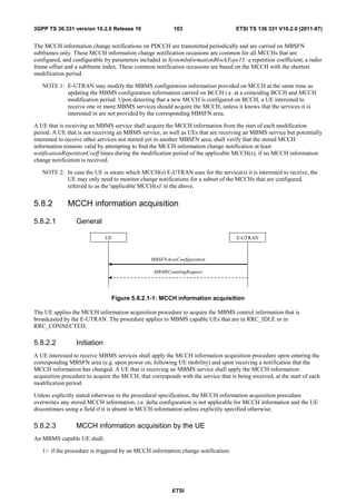
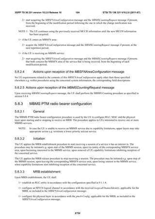
![3GPP TS 36.331 version 10.2.0 Release 10 106 ETSI TS 136 331 V10.2.0 (2011-07)
2> submit the MBMSCountingResponse message to lower layers for transmission upon which the procedure
ends;
NOTE 1: UEs that are receiving an MBMS User Service [56] by means of a Unicast Bearer Service [57] (i.e. via a
DRB), but are interested to receive the concerned MBMS User Service [56] via an MBMS Bearer Service
(i.e. via an MRB), respond to the counting request.
NOTE 2: The UE treats the MBMSCountingRequest messages received in each modification period independently.
In the unlikely case E-UTRAN would repeat an MBMSCountingRequest (i.e. including the same services)
in a subsequent modification period, the UE responds again.
5.9 RN procedures
5.9.1 RN reconfiguration
5.9.1.1 General
RN EUTRAN
RNReconfiguration
RNReconfigurationComplete
Figure 5.9.1.1-1: RN reconfiguration
The purpose of this procedure is to configure/reconfigure the RN subframe configuration and/or to update the system
information relevant for the RN in RRC_CONNECTED.
5.9.1.2 Initiation
E-UTRAN may initiate the RN reconfiguration procedure to an RN in RRC_CONNECTED when AS security has been
activated.
5.9.1.3 Reception of the RNReconfiguration by the RN
The RN shall:
1> if the rn-SystemInfo is included:
2> if the systemInformationBlockType1 is included:
3> act upon the received SystemInformationBlockType1 as specified in 5.2.2.7;
2> if the SystemInformationBlockType2 is included:
3> act upon the received SystemInformationBlockType2 as specified in 5.2.2.9;
1> if the rn-SubframeConfig is included:
2> reconfigure lower layers in accordance with the received subframeConfigPatternFDD or
subframeConfigPatternTDD;
2> if the rpdcch-Config is included:
ETSI](https://image.slidesharecdn.com/ts136331v100200p-111014005410-phpapp02/85/Ts-136331v100200p-107-320.jpg)
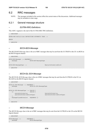
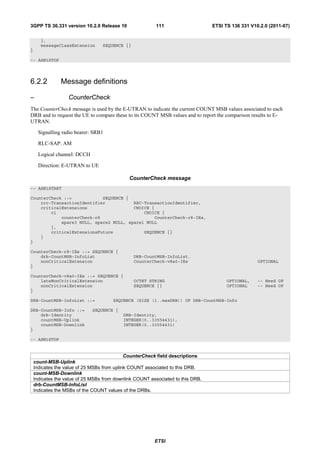
![3GPP TS 36.331 version 10.2.0 Release 10 115 ETSI TS 136 331 V10.2.0 (2011-07)
spare3 NULL, spare2 NULL, spare1 NULL
},
criticalExtensionsFuture SEQUENCE {}
}
}
HandoverFromEUTRAPreparationRequest-r8-IEs ::= SEQUENCE {
cdma2000-Type CDMA2000-Type,
rand RAND-CDMA2000 OPTIONAL, -- Cond cdma2000-Type
mobilityParameters MobilityParametersCDMA2000 OPTIONAL, -- Cond cdma2000-Type
nonCriticalExtension HandoverFromEUTRAPreparationRequest-v890-IEs OPTIONAL
}
HandoverFromEUTRAPreparationRequest-v890-IEs ::= SEQUENCE {
lateNonCriticalExtension OCTET STRING OPTIONAL, -- Need OP
nonCriticalExtension HandoverFromEUTRAPreparationRequest-v920-IEs OPTIONAL
}
HandoverFromEUTRAPreparationRequest-v920-IEs ::= SEQUENCE {
concurrPrepCDMA2000-HRPD-r9 BOOLEAN OPTIONAL, -- Cond cdma2000-Type
nonCriticalExtension HandoverFromEUTRAPreparationRequest-v1020-IEs OPTIONAL
}
HandoverFromEUTRAPreparationRequest-v1020-IEs ::= SEQUENCE {
dualRxTxRedirectIndicator-r10 ENUMERATED {true} OPTIONAL, -- Cond cdma2000-1XRTT
redirectCarrierCDMA2000-1XRTT-r10 CarrierFreqCDMA2000 OPTIONAL, -- Cond dualRxTxRedirect
nonCriticalExtension SEQUENCE {} OPTIONAL -- Need OP
}
-- ASN1STOP
HandoverFromEUTRAPreparationRequest field descriptions
concurrPrepCDMA2000-HRPD
Value TRUE indicates that upper layers should initiate concurrent preparation for handover to CDMA2000 HRPD in
addition to preparation for enhanced CS fallback to CDMA2000 1xRTT.
dualRxTxRedirectIndicator
Value TRUE indicates that the second radio of the dual Rx/Tx UE is being redirected to CDMA2000 1xRTT [51].
redirectCarrierCDMA2000-1XRTT
Used to indicate the CDMA2000 1xRTT carrier frequency where the UE is being redirected to.
Conditional presence Explanation
cdma2000-1XRTT The field is optionally present, need ON, if the cdma2000-Type = type1XRTT; otherwise it
is not present.
cdma2000-Type The field is mandatory present if the cdma2000-Type = type1XRTT; otherwise it is not
present.
dualRxTxRedirect The field is optionally present, need ON, if dualRxTxRedirectIndicator is present;
otherwise it is not present.
– InterFreqRSTDMeasurementIndication
The InterFreqRSTDMeasurementIndication message is used to indicate that the UE is going to either start or stop
OTDOA inter-frequency RSTD measurement which requires measurement gaps as specified in TS 36.133 [16, 8.1.2.6].
Signalling radio bearer: SRB1
RLC-SAP: AM
Logical channel: DCCH
Direction: UE to E-UTRAN
InterFreqRSTDMeasurementIndication message
-- ASN1START
InterFreqRSTDMeasurementIndication-r10 ::= SEQUENCE {
ETSI](https://image.slidesharecdn.com/ts136331v100200p-111014005410-phpapp02/85/Ts-136331v100200p-116-320.jpg)
![3GPP TS 36.331 version 10.2.0 Release 10 116 ETSI TS 136 331 V10.2.0 (2011-07)
criticalExtensions CHOICE {
c1 CHOICE {
interFreqRSTDMeasurementIndication-r10 InterFreqRSTDMeasurementIndication-r10-IEs,
spare3 NULL, spare2 NULL, spare1 NULL
},
criticalExtensionsFuture SEQUENCE {}
}
}
InterFreqRSTDMeasurementIndication-r10-IEs ::= SEQUENCE {
rstd-InterFreqIndication-r10 CHOICE {
start SEQUENCE {
rstd-InterFreqInfoList-r10 RSTD-InterFreqInfoList-r10
},
stop NULL
},
lateNonCriticalExtension OCTET STRING OPTIONAL,
nonCriticalExtension SEQUENCE {} OPTIONAL
}
RSTD-InterFreqInfoList-r10 ::= SEQUENCE (SIZE(1..maxRSTD-Freq-r10)) OF RSTD-InterFreqInfo-r10
RSTD-InterFreqInfo-r10 ::= SEQUENCE {
carrierFreq-r10 ARFCN-ValueEUTRA,
measPRS-Offset-r10 INTEGER (0..39),
...
}
-- ASN1STOP
InterFreqRSTDMeasurementIndication field descriptions
carrierFreq
The EARFCN value of the carrier received from upper layers for which the UE needs to perform the inter-frequency
RSTD measurements.
measPRS-Offset
Indicates the smallest offset of the PRS positioning occasions in the carrier frequency carrierFreq for which the UE
needs to perform the inter-frequency RSTD measurements. The PRS positioning occasion information is received
from upper layers. The value of measPRS-Offset is obtained by mapping the starting subframe of the PRS positioning
occasion in the measured cell to the corresponding subframe in the serving cell and is calculated as the serving cell’s
subframe number mod 40ms.
rstd-InterFreqIndication
Indicates the inter-frequency RSTD measurement action, i.e. the UE is going to start or stop inter-frequency RSTD
measurement.
– LoggedMeasurementConfiguration
The LoggedMeasurementConfiguration message is used by E-UTRAN to configure the UE to perform logging of
measurement results while in RRC_IDLE. It is used to transfer the logged measurement configuration for network
performance optimisation, see TS 37.320 [60].
Signalling radio bearer: SRB1
RLC-SAP: AM
Logical channel: DCCH
Direction: E-UTRAN to UE
LoggedMeasurementConfiguration message
-- ASN1START
LoggedMeasurementConfiguration-r10 ::= SEQUENCE {
criticalExtensions CHOICE {
c1 CHOICE {
loggedMeasurementConfiguration-r10 LoggedMeasurementConfiguration-r10-IEs,
spare3 NULL, spare2 NULL, spare1 NULL
},
criticalExtensionsFuture SEQUENCE {}
}
ETSI](https://image.slidesharecdn.com/ts136331v100200p-111014005410-phpapp02/85/Ts-136331v100200p-117-320.jpg)
![3GPP TS 36.331 version 10.2.0 Release 10 117 ETSI TS 136 331 V10.2.0 (2011-07)
}
LoggedMeasurementConfiguration-r10-IEs ::= SEQUENCE {
traceReference-r10 TraceReference-r10,
traceRecordingSessionRef-r10 OCTET STRING (SIZE (2)),
tce-Id-r10 OCTET STRING (SIZE (1)),
absoluteTimeInfo-r10 AbsoluteTimeInfo-r10,
areaConfiguration-r10 AreaConfiguration-r10 OPTIONAL, -- Need OR
loggingDuration-r10 LoggingDuration-r10,
loggingInterval-r10 LoggingInterval-r10,
nonCriticalExtension SEQUENCE {} OPTIONAL -- Need OP
}
-- ASN1STOP
LoggedMeasurementConfiguration field descriptions
absoluteTimeInfo
Indicates the absolute time in the current cell.
tce-Id
Parameter Trace Collection Entity Id: See TS 32.422 [58].
traceRecordingSessionRef
Parameter Trace Recording Session Reference: See TS 32.422 [58]
– MasterInformationBlock
The MasterInformationBlock includes the system information transmitted on BCH.
Signalling radio bearer: N/A
RLC-SAP: TM
Logical channel: BCCH
Direction: E-UTRAN to UE
MasterInformationBlock
-- ASN1START
MasterInformationBlock ::= SEQUENCE {
dl-Bandwidth ENUMERATED {
n6, n15, n25, n50, n75, n100},
phich-Config PHICH-Config,
systemFrameNumber BIT STRING (SIZE (8)),
spare BIT STRING (SIZE (10))
}
-- ASN1STOP
MasterInformationBlock field descriptions
dl-Bandwidth
Parameter: transmission bandwidth configuration, NRB in downlink, see TS 36.101 [42, table 5.6-1]. n6 corresponds to
6 resource blocks, n15 to 15 resource blocks and so on.
systemFrameNumber
Defines the 8 most significant bits of the SFN. As indicated in TS 36.211 [21, 6.6.1], the 2 least significant bits of the
SFN are acquired implicitly in the P-BCH decoding, i.e. timing of 40ms P-BCH TTI indicates 2 least significant bits
(within 40ms P-BCH TTI, the first radio frame: 00, the second radio frame: 01, the third radio frame: 10, the last radio
frame: 11). One value apples for all serving cells (the associated functionality is common i.e. not performed
independently for each cell).
ETSI](https://image.slidesharecdn.com/ts136331v100200p-111014005410-phpapp02/85/Ts-136331v100200p-118-320.jpg)
![3GPP TS 36.331 version 10.2.0 Release 10 122 ETSI TS 136 331 V10.2.0 (2011-07)
MobilityFromEUTRACommand field descriptions
bandIndicator
Indicates how to interpret the ARFCN of the BCCH carrier.
carrierFreq
contains the carrier frequency of the target GERAN cell.
cs-FallbackIndicator
Value true indicates that the CS Fallback procedure to UTRAN or GERAN is triggered.
messageContCDMA2000-1XRTT
This field contains a message specified in CDMA2000 1xRTT standard that either tells the UE to move to specific
1xRTT target cell(s) or indicates a failure to allocate resources for the enhanced CS fallback to CDMA2000 1xRTT.
messageContCDMA2000-HRPD
This field contains a message specified in CDMA2000 HRPD standard that either tells the UE to move to specific
HRPD target cell(s) or indicates a failure to allocate resources for the handover to CDMA2000 HRPD.
mobilityCDMA2000-HRPD
This field indicates whether or not mobility to CDMA2000 HRPD is to be performed by the UE and it also indicates the
type of mobility to CDMA2000 HRPD that is to be performed; If this field is not present the UE shall perform only the
enhanced CS fallback to CDMA2000 1xRTT.
nas-SecurityParamFromEUTRA
Used to deliver the key synchronisation and Key freshness for the E-UTRAN to UTRAN handovers as specified in TS
33.401. The content of the parameter is defined in TS24.301.
networkControlOrder
Parameter NETWORK_CONTROL_ORDER in TS 44.060 [36].
purpose
Indicates which type of mobility procedure the UE is requested to perform. EUTRAN always applies value e-CSFB in
case of enhanced CS fallback to CDMA2000 (e.g. also when that procedure results in handover to CDMA2000 1XRTT
only, in handover to CDMA2000 HRPD only or in redirection to CDMA2000 HRPD only),
redirectCarrierCDMA2000-HRPD
The redirectCarrierCDMA2000-HRPD indicates a CDMA2000 carrier frequency and is used to redirect the UE to a
HRPD carrier frequency.
SystemInfoListGERAN
If purpose = CellChangeOrder and if the field is not present, the UE has to acquire SI/PSI from the GERAN cell.
t304
Timer T304 as described in section 7.3. Value ms100 corresponds with 100 ms, ms200 corresponds with 200 ms and
so on.
targetRAT-Type
Indicates the target RAT type.
targetRAT-MessageContainer
The field contains a message specified in another standard, as indicated by the targetRAT-Type, and carries
information about the target cell identifier(s) and radio parameters relevant for the target radio access technology.
NOTE 1.
A complete message is included, as specified in the other standard.
Conditional presence Explanation
concHO The field is mandatory present if the mobilityCDMA2000-HRPD is set to “handover”;
otherwise the field is optional present, need ON.
concRedir The field is mandatory present if the mobilityCDMA2000-HRPD is set to “redirection”;
otherwise the field is not present.
GERAN The field should be present if the purpose is set to “handover” and the targetRAT-Type is
set to “geran”; otherwise the field is not present
PSHO The field is mandatory present in case of PS handover toward GERAN; otherwise the
field is optionally present, but not used by the UE
UTRAGERAN The field is mandatory present if the targetRAT-Type is set to “utra” or “geran”; otherwise
the field is not present
NOTE 1: The correspondence between the value of the targetRAT-Type, the standard to apply and the message
contained within the targetRAT-MessageContainer is shown in the table below:
ETSI](https://image.slidesharecdn.com/ts136331v100200p-111014005410-phpapp02/85/Ts-136331v100200p-123-320.jpg)
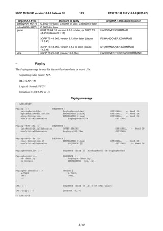
![3GPP TS 36.331 version 10.2.0 Release 10 124 ETSI TS 136 331 V10.2.0 (2011-07)
Paging field descriptions
cmas-Indication
If present: indication of a CMAS notification.
cn-Domain
Indicates the origin of paging.
etws-Indication
If present: indication of an ETWS primary notification and/ or ETWS secondary notification.
imsi
The International Mobile Subscriber Identity, a globally unique permanent subscriber identity, see TS 23.003 [27]. The
first element contains the first IMSI digit, the second element contains the second IMSI digit and so on.
systemInfoModification
If present: indication of a BCCH modification other than SIB10, SIB11 and SIB12.
ue-Identity
Provides the NAS identity of the UE that is being paged.
– ProximityIndication
The ProximityIndication message is used to indicate that the UE is entering or leaving the proximity of one or more
cells whose CSG IDs are in the UEs CSG whitelist.
Signalling radio bearer: SRB1
RLC-SAP: AM
Logical channel: DCCH
Direction: UE to E-UTRAN
ProximityIndication message
-- ASN1START
ProximityIndication-r9 ::= SEQUENCE {
criticalExtensions CHOICE {
c1 CHOICE {
proximityIndication-r9 ProximityIndication-r9-IEs,
spare3 NULL, spare2 NULL, spare1 NULL
},
criticalExtensionsFuture SEQUENCE {}
}
}
ProximityIndication-r9-IEs ::= SEQUENCE {
type-r9 ENUMERATED {entering, leaving},
carrierFreq-r9 CHOICE {
eutra-r9 ARFCN-ValueEUTRA,
utra-r9 ARFCN-ValueUTRA,
...
},
nonCriticalExtension ProximityIndication-v930-IEs
OPTIONAL
}
ProximityIndication-v930-IEs ::= SEQUENCE {
lateNonCriticalExtension OCTET STRING OPTIONAL,
nonCriticalExtension SEQUENCE {} OPTIONAL
}
-- ASN1STOP
ProximityIndication field descriptions
carrierFreq
Indicates the RAT and frequency of the cell(s), whose CSG IDs are in the UEs CSG whitelist, for which the proximity
indication is sent.
type
Used to indicate whether the UE is entering or leaving the proximity of cell(s) whose CSG IDs are in the UEs CSG
whitelist.
ETSI](https://image.slidesharecdn.com/ts136331v100200p-111014005410-phpapp02/85/Ts-136331v100200p-125-320.jpg)
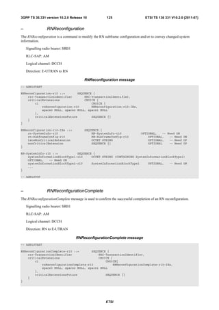
![3GPP TS 36.331 version 10.2.0 Release 10 127 ETSI TS 136 331 V10.2.0 (2011-07)
dl-CarrierFreq-r10 ARFCN-ValueEUTRA
} OPTIONAL, -- Cond SCellAdd
radioResourceConfigCommonSCell-r10 RadioResourceConfigCommonSCell-r10 OPTIONAL, -- Cond
SCellAdd
radioResourceConfigDedicatedSCell-r10 RadioResourceConfigDedicatedSCell-r10 OPTIONAL, --
Cond SCellAdd2
...
}
SCellToReleaseList-r10 ::= SEQUENCE (SIZE (1..maxSCell-r10)) OF SCellIndex-r10
SecurityConfigHO ::= SEQUENCE {
handoverType CHOICE {
intraLTE SEQUENCE {
securityAlgorithmConfig SecurityAlgorithmConfig OPTIONAL, -- Cond
fullConfig
keyChangeIndicator BOOLEAN,
nextHopChainingCount NextHopChainingCount
},
interRAT SEQUENCE {
securityAlgorithmConfig SecurityAlgorithmConfig,
nas-SecurityParamToEUTRA OCTET STRING (SIZE(6))
}
},
...
}
-- ASN1STOP
RRCConnectionReconfiguration field descriptions
dedicatedInfoNASList
This field is used to transfer UE specific NAS layer information between the network and the UE. The RRC layer is
transparent for each PDU in the list.
fullConfig
Indicates the full configuration option is applicable for the RRC Connection Reconfiguration message.
keyChangeIndicator
true is used only in an intra-cell handover when a KeNB key is derived from a native KASME key taken into use through
the successful NAS SMC, as described in TS 33.401 [32] for KeNB re-keying. false is used in an intra-LTE handover
when the new KeNB key is obtained from the current KeNB key or from the NH as described in TS 33.401 [32].
nas-securityParamToEUTRA
This field is used to transfer UE specific NAS layer information between the network and the UE. The RRC layer is
transparent for this field, although it affects activation of AS- security after inter-RAT handover to E-UTRA. The
content is defined in TS 24.301.
nextHopChainingCount
Parameter NCC: See TS 33.401 [32]
Conditional presence Explanation
fullConfig This field is mandatory present for handover within E-UTRA when the fullConfig is
included; otherwise it is optionally present, Need OP.
HO The field is mandatory present in case of handover within E-UTRA or to E-UTRA;
otherwise the field is not present.
HO-Reestab This field is optionally present, need ON, in case of handover within E-UTRA or upon the
first reconfiguration after RRC connection re-establishment; otherwise the field is not
present.
HO-toEUTRA The field is mandatory present in case of handover to E-UTRA or for reconfigurations
when fullConfig is included; otherwise the field is optionally present, need ON.
nonHO The field is not present in case of handover within E-UTRA or to E-UTRA; otherwise it is
optional present, need ON.
SCellAdd The field is mandatory present upon SCell addition; otherwise it is not present.
SCellAdd2 The field is mandatory present upon SCell addition; otherwise it is optionally present,
need ON.
ETSI](https://image.slidesharecdn.com/ts136331v100200p-111014005410-phpapp02/85/Ts-136331v100200p-128-320.jpg)
![3GPP TS 36.331 version 10.2.0 Release 10 134 ETSI TS 136 331 V10.2.0 (2011-07)
RRCConnectionRelease field descriptions
carrierFreq or bandClass
The carrier frequency (UTRA and E-UTRA) and band class (HRPD and 1xRTT) for which the associated
cellReselectionPriority is applied.
carrierFreqs
The list of GERAN carrier frequencies organised into one group of GERAN carrier frequencies.
cellInfoList
Used to provide system information of one or more cells on the redirected inter-RAT carrier frequency. The system
information can be used if, upon redirection, the UE selects an inter-RAT cell indicated by the physCellId and
carrierFreq (GERAN and UTRA TDD) or by the physCellId (other RATs). The choice shall match the
redirectedCarrierInfo.
extendedWaitTime
Value in seconds for the wait time for Delay Tolerant access requests.
freqPriorityListX
Provides a cell reselection priority for each frequency, by means of separate lists for each RAT (including E-UTRA).
idleModeMobilityControlInfo
Provides dedicated cell reselection priorities. Used for cell reselection as specified in TS 36.304 [4].
redirectedCarrierInfo
The redirectedCarrierInfo indicates a carrier frequency (downlink for FDD) and is used to redirect the UE to an
E-UTRA or an inter-RAT carrier frequency, by means of the cell selection upon leaving RRC_CONNECTED as
specified in TS 36.304 [4]. E-UTRAN only applies value utra-TDD-r10 for redirectedCarrierInfo if cellInfoList-r9 is set to
utra-TDD-r10.
releaseCause
The releaseCause is used to indicate the reason for releasing the RRC Connection. The cause value cs-
FallbackHighPriority is only applicable when redirectedCarrierInfo is present with the value set to utra-FDD or utra-
TDD.
E-UTRAN should not set the releaseCause to loadBalancingTAURequired or to cs-FallbackHighPriority if the
extendedWaitTime is present.
systemInformation
Container for system information of the GERAN cell. Each OCTET STRING in SystemInfoListGERAN contains one
complete System Information (SI) message as defined in TS 44.018 [45, table 9.1.1].
t320
Timer T320 as described in section 7.3. Value minN corresponds to N minutes.
utra-BCCH-Container
Contains System Information Container message as defined in TS 25.331 [19].
Conditional presence Explanation
Redirection The field is optionally present, need ON, if the redirectedCarrierInfo is included and set to
geran, utra-FDD, utra-TDD or utra-TDD-r10; otherwise the field is not present.
– RRCConnectionRequest
The RRCConnectionRequest message is used to request the establishment of an RRC connection.
Signalling radio bearer: SRB0
RLC-SAP: TM
Logical channel: CCCH
Direction: UE to E-UTRAN
RRCConnectionRequest message
-- ASN1START
RRCConnectionRequest ::= SEQUENCE {
criticalExtensions CHOICE {
rrcConnectionRequest-r8 RRCConnectionRequest-r8-IEs,
criticalExtensionsFuture SEQUENCE {}
}
}
RRCConnectionRequest-r8-IEs ::= SEQUENCE {
ue-Identity InitialUE-Identity,
establishmentCause EstablishmentCause,
ETSI](https://image.slidesharecdn.com/ts136331v100200p-111014005410-phpapp02/85/Ts-136331v100200p-135-320.jpg)
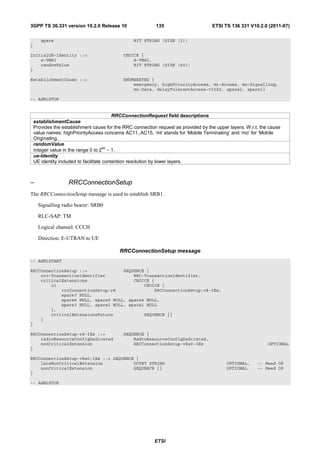
![3GPP TS 36.331 version 10.2.0 Release 10 136 ETSI TS 136 331 V10.2.0 (2011-07)
– RRCConnectionSetupComplete
The RRCConnectionSetupComplete message is used to confirm the successful completion of an RRC connection
establishment.
Signalling radio bearer: SRB1
RLC-SAP: AM
Logical channel: DCCH
Direction: UE to E-UTRAN
RRCConnectionSetupComplete message
-- ASN1START
RRCConnectionSetupComplete ::= SEQUENCE {
rrc-TransactionIdentifier RRC-TransactionIdentifier,
criticalExtensions CHOICE {
c1 CHOICE{
rrcConnectionSetupComplete-r8 RRCConnectionSetupComplete-r8-IEs,
spare3 NULL, spare2 NULL, spare1 NULL
},
criticalExtensionsFuture SEQUENCE {}
}
}
RRCConnectionSetupComplete-r8-IEs ::= SEQUENCE {
selectedPLMN-Identity INTEGER (1..6),
registeredMME RegisteredMME OPTIONAL,
dedicatedInfoNAS DedicatedInfoNAS,
nonCriticalExtension RRCConnectionSetupComplete-v8a0-IEs OPTIONAL
}
RRCConnectionSetupComplete-v8a0-IEs ::= SEQUENCE {
lateNonCriticalExtension OCTET STRING OPTIONAL,
nonCriticalExtension RRCConnectionSetupComplete-v1020-IEs OPTIONAL
}
RRCConnectionSetupComplete-v1020-IEs ::= SEQUENCE {
gummei-Type-r10 ENUMERATED {native, mapped} OPTIONAL,
rlf-InfoAvailable-r10 ENUMERATED {true} OPTIONAL,
logMeasAvailable-r10 ENUMERATED {true} OPTIONAL,
rn-SubframeConfigReq-r10 ENUMERATED {required, notRequired} OPTIONAL,
nonCriticalExtension SEQUENCE {} OPTIONAL
}
RegisteredMME ::= SEQUENCE {
plmn-Identity PLMN-Identity OPTIONAL,
mmegi BIT STRING (SIZE (16)),
mmec MMEC
}
-- ASN1STOP
RRCConnectionSetupComplete field descriptions
gummei-Type
This field is used to indicate whether the GUMMEI included is native (assigned by EPC) or mapped (from 2G/3G
identifiers).
mmegi
Provides the Group Identity of the registered MME within the PLMN, as provided by upper layers, see TS 23.003 [27].
registeredMME
This field is used to transfer the GUMMEI of the MME where the UE is registered, as provided by upper layers.
rn-SubframeConfigReq
If present, this field indicates that the connection establishment is for an RN and whether a subframe configuration is
requested or not.
selectedPLMN-Identity
Index of the PLMN selected by the UE from the plmn-IdentityList included in SIB1. 1 if the 1st PLMN is selected from
the plmn-IdentityList included in SIB1, 2 if the 2nd PLMN is selected from the plmn-IdentityList included in SIB1 and so
on.
ETSI](https://image.slidesharecdn.com/ts136331v100200p-111014005410-phpapp02/85/Ts-136331v100200p-137-320.jpg)
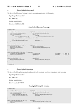
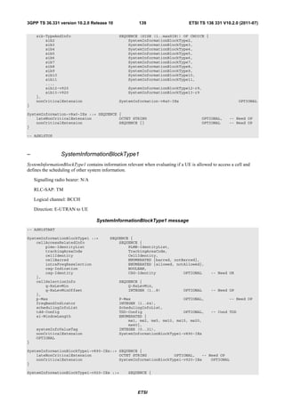
![3GPP TS 36.331 version 10.2.0 Release 10 141 ETSI TS 136 331 V10.2.0 (2011-07)
SystemInformationBlockType1 field descriptions
cellBarred
barred means the cell is barred, as defined in TS 36.304 [4].
cellReservedForOperatorUse
As defined in TS 36.304 [4].
csg-Identity
Identity of the Closed Subscriber Group within the primary PLMN the cell belongs to.
csg-Indication
If set to TRUE the UE is only allowed to access the cell if the CSG identity matches an entry in the CSG whitelist that
the UE has stored.
freqBandIndicator
Defined in TS 36.101 [42, table 5.5-1].
ims-EmergencySupport
Indicates whether the cell supports IMS emergency bearer services for UEs in limited service mode. If absent, IMS
emergency call is not supported by the network in the cell for UEs in limited service mode.
intraFreqReselection
Used to control cell reselection to intra-frequency cells when the highest ranked cell is barred, or treated as barred by
the UE, as specified in TS 36.304 [4].
plmn-IdentityList
List of PLMN identities. The first listed PLMN-Identity is the primary PLMN.
p-Max
Value applicable for the cell. If absent the UE applies the maximum power according to the UE capability.
q-QualMin
Parameter “Qqualmin” in TS 36.304 [4]. If cellSelectionInfo-v920 is not present, the UE applies the (default) value of
negative infinity for Qqualmin.
q-QualMinOffset
Parameter “Qqualminoffset” in TS 36.304 [4]. Actual value Qqualminoffset = IE value [dB]. If cellSelectionInfo-v920 is not
present or the field is not present, the UE applies the (default) value of 0 dB for Qqualminoffset. Affects the minimum
required quality level in the cell.
q-RxLevMinOffset
Parameter Qrxlevminoffset in TS 36.304 [4]. Actual value Qrxlevminoffset = IE value * 2 [dB]. If absent, the UE applies the
(default) value of 0 dB for Qrxlevminoffset. Affects the minimum required Rx level in the cell.
sib-MappingInfo
List of the SIBs mapped to this SystemInformation message.There is no mapping information of SIB2; it is always
present in the first SystemInformation message listed in the schedulingInfoList list.
si-Periodicity
Periodicity of the SI-message in radio frames, such that rf8 denotes 8 radio frames, rf16 denotes 16 radio frames, and
so on.
si-WindowLength
Common SI scheduling window for all SIs. Unit in milliseconds, where ms1 denotes 1 millisecond, ms2 denotes 2
milliseconds and so on.
systemInfoValueTag
Common for all SIBs other than MIB, SIB1, SIB10, SIB11 and SIB12. Change of MIB and SIB1 is detected by
acquisition of the corresponding message.
trackingAreaCode
A trackingAreaCode that is common for all the PLMNs listed.
Conditional presence Explanation
RSRQ The field is mandatory present if SIB3 is being broadcast and threshServingLowQ is
present in SIB3; otherwise optionally present, Need OP.
TDD This field is mandatory present for TDD; it is not present for FDD and the UE shall delete
any existing value for this field.
– UECapabilityEnquiry
The UECapabilityEnquiry message is used to request the transfer of UE radio access capabilities for E-UTRA as well
as for other RATs.
ETSI](https://image.slidesharecdn.com/ts136331v100200p-111014005410-phpapp02/85/Ts-136331v100200p-142-320.jpg)
![3GPP TS 36.331 version 10.2.0 Release 10 144 ETSI TS 136 331 V10.2.0 (2011-07)
RLC-SAP: AM
Logical channel: DCCH
Direction: UE to E-UTRAN
UEInformationResponse message
-- ASN1START
UEInformationResponse-r9 ::= SEQUENCE {
rrc-TransactionIdentifier RRC-TransactionIdentifier,
criticalExtensions CHOICE {
c1 CHOICE {
ueInformationResponse-r9 UEInformationResponse-r9-IEs,
spare3 NULL, spare2 NULL, spare1 NULL
},
criticalExtensionsFuture SEQUENCE {}
}
}
UEInformationResponse-r9-IEs ::= SEQUENCE {
rach-Report-r9 SEQUENCE {
numberOfPreamblesSent-r9 INTEGER (1..200),
contentionDetected-r9 BOOLEAN
} OPTIONAL,
rlf-Report-r9 RLF-Report-r9 OPTIONAL,
nonCriticalExtension UEInformationResponse-v930-IEs OPTIONAL
}
UEInformationResponse-v930-IEs ::= SEQUENCE {
lateNonCriticalExtension OCTET STRING OPTIONAL,
nonCriticalExtension UEInformationResponse-v1020-IEs OPTIONAL
}
UEInformationResponse-v1020-IEs ::= SEQUENCE {
logMeasReport-r10 LogMeasReport-r10 OPTIONAL,
nonCriticalExtension SEQUENCE {} OPTIONAL
}
RLF-Report-r9 ::= SEQUENCE {
measResultLastServCell-r9 SEQUENCE {
rsrpResult-r9 RSRP-Range,
rsrqResult-r9 RSRQ-Range OPTIONAL
},
measResultNeighCells-r9 SEQUENCE {
measResultListEUTRA-r9 MeasResultList2EUTRA-r9 OPTIONAL,
measResultListUTRA-r9 MeasResultList2UTRA-r9 OPTIONAL,
measResultListGERAN-r9 MeasResultListGERAN OPTIONAL,
measResultsCDMA2000-r9 MeasResultList2CDMA2000-r9 OPTIONAL
} OPTIONAL,
...,
[[ locationInfo-r10 LocationInfo-r10 OPTIONAL,
failedPCellId-r10 CHOICE {
cellGlobalId-r10 CellGlobalIdEUTRA,
pci-arfcn-r10 SEQUENCE {
physCellId-r10 PhysCellId,
carrierFreq-r10 ARFCN-ValueEUTRA
}
} OPTIONAL,
reestablishmentCellId-r10 CellGlobalIdEUTRA OPTIONAL,
timeConnFailure-r10 INTEGER (0..1023) OPTIONAL,
connectionFailureType-r10 ENUMERATED {rlf, hof} OPTIONAL,
previousPCellId-r10 CellGlobalIdEUTRA OPTIONAL
]]
}
MeasResultList2EUTRA-r9 ::= SEQUENCE (SIZE (1..maxFreq)) OF MeasResult2EUTRA-r9
MeasResult2EUTRA-r9 ::= SEQUENCE {
carrierFreq-r9 ARFCN-ValueEUTRA,
measResultList-r9 MeasResultListEUTRA
}
MeasResultList2UTRA-r9 ::= SEQUENCE (SIZE (1..maxFreq)) OF MeasResult2UTRA-r9
MeasResult2UTRA-r9 ::= SEQUENCE {
ETSI](https://image.slidesharecdn.com/ts136331v100200p-111014005410-phpapp02/85/Ts-136331v100200p-145-320.jpg)
![3GPP TS 36.331 version 10.2.0 Release 10 146 ETSI TS 136 331 V10.2.0 (2011-07)
UEInformationResponse field descriptions
absoluteTimeStamp
Indicates the absolute time when the logged measurement configuration logging is provided, as indicated by E-
UTRAN within absoluteTimeInfo.
connectionFailureType
This field is used to indicate whether the connection failure is due to radio link failure or handover failure.
contentionDetected
This field is used to indicate that contention was detected for at least one of the transmitted preambles, see also [6].
failedPCellId
This field is used to indicate the PCell in which RLF is detected or the target PCell of the failed handover.
measResultLastServCell
This field refers to the last measurement results taken in the PCell, where radio link failure happened.
numberOfPreamblesSent
This field is used to indicate the number of RACH preambles that were transmitted. Corresponds to parameter
PREAMBLE_TRANSMISSION_COUNTER in TS 36.321 [6].
previousPCellId
This field is used to indicate the source PCell of the last handover (source PCell when the last RRC-Connection-
Reconfiguration message including mobilityControlInfowas received).
reestablishmentCellId
This field is used to indicate the cell in which the re-establishment attempt was made after connection failure.
relativeTimeStamp
Indicates the time of logging measurement results, measured relative to the absoluteTimeStamp. Value in seconds.
tce-Id
Parameter Trace Collection Entity Id: See TS 32.422 [58].
timeConnFailure
This field is used to indicate the time elapsed since the last HO initialization until connection failure. Actual value = IE
value * 100ms. The maximum value 1023 means 102.3s or longer.
traceRecordingSessionRef
Parameter Trace Recording Session Reference: See TS 32.422 [58].
– ULHandoverPreparationTransfer (CDMA2000)
The ULHandoverPreparationTransfer message is used for the uplink transfer of handover related CDMA2000
information when requested by the higher layers.
Signalling radio bearer: SRB1
RLC-SAP: AM
Logical channel: DCCH
Direction: UE to E-UTRAN
ULHandoverPreparationTransfer message
-- ASN1START
ULHandoverPreparationTransfer ::= SEQUENCE {
criticalExtensions CHOICE {
c1 CHOICE {
ulHandoverPreparationTransfer-r8 ULHandoverPreparationTransfer-r8-IEs,
spare3 NULL, spare2 NULL, spare1 NULL
},
criticalExtensionsFuture SEQUENCE {}
}
}
ULHandoverPreparationTransfer-r8-IEs ::= SEQUENCE {
cdma2000-Type CDMA2000-Type,
meid BIT STRING (SIZE (56)) OPTIONAL,
dedicatedInfo DedicatedInfoCDMA2000,
nonCriticalExtension ULHandoverPreparationTransfer-v8a0-IEs
OPTIONAL
}
ULHandoverPreparationTransfer-v8a0-IEs ::= SEQUENCE {
lateNonCriticalExtension OCTET STRING OPTIONAL,
nonCriticalExtension SEQUENCE {} OPTIONAL
}
ETSI](https://image.slidesharecdn.com/ts136331v100200p-111014005410-phpapp02/85/Ts-136331v100200p-147-320.jpg)
![3GPP TS 36.331 version 10.2.0 Release 10 148 ETSI TS 136 331 V10.2.0 (2011-07)
SystemInformationBlockType2 ::= SEQUENCE {
ac-BarringInfo SEQUENCE {
ac-BarringForEmergency BOOLEAN,
ac-BarringForMO-Signalling AC-BarringConfig OPTIONAL, -- Need OP
ac-BarringForMO-Data AC-BarringConfig OPTIONAL -- Need OP
} OPTIONAL, -- Need OP
radioResourceConfigCommon RadioResourceConfigCommonSIB,
ue-TimersAndConstants UE-TimersAndConstants,
freqInfo SEQUENCE {
ul-CarrierFreq ARFCN-ValueEUTRA OPTIONAL, -- Need OP
ul-Bandwidth ENUMERATED {n6, n15, n25, n50, n75, n100}
OPTIONAL, -- Need OP
additionalSpectrumEmission AdditionalSpectrumEmission
},
mbsfn-SubframeConfigList MBSFN-SubframeConfigList OPTIONAL, -- Need OR
timeAlignmentTimerCommon TimeAlignmentTimer,
...,
lateNonCriticalExtension OCTET STRING OPTIONAL, -- Need OP
[[ ssac-BarringForMMTEL-Voice-r9 AC-BarringConfig OPTIONAL, -- Need OP
ssac-BarringForMMTEL-Video-r9 AC-BarringConfig OPTIONAL -- Need OP
]],
[[ ac-BarringForCSFB-r10 AC-BarringConfig OPTIONAL -- Need OP
]]
}
AC-BarringConfig ::= SEQUENCE {
ac-BarringFactor ENUMERATED {
p00, p05, p10, p15, p20, p25, p30, p40,
p50, p60, p70, p75, p80, p85, p90, p95},
ac-BarringTime ENUMERATED {s4, s8, s16, s32, s64, s128, s256, s512},
ac-BarringForSpecialAC BIT STRING (SIZE(5))
}
MBSFN-SubframeConfigList ::= SEQUENCE (SIZE (1..maxMBSFN-Allocations)) OF MBSFN-
SubframeConfig
-- ASN1STOP
ETSI](https://image.slidesharecdn.com/ts136331v100200p-111014005410-phpapp02/85/Ts-136331v100200p-149-320.jpg)
![3GPP TS 36.331 version 10.2.0 Release 10 149 ETSI TS 136 331 V10.2.0 (2011-07)
SystemInformationBlockType2 field descriptions
ac-BarringFactor
If the random number drawn by the UE is lower than this value, access is allowed. Otherwise the access is barred.
The values are interpreted in the range [0,1): p00 = 0, p05 = 0.05, p10 = 0.10,…,p95 = 0.95. Values other than p00
can only be set if all bits of the corresponding ac-BarringForSpecialAC are set to 0.
ac-BarringForCSFB
Access class barring for mobile originating CS fallback.
ac-BarringForEmergency
Access class barring for AC 10.
ac-BarringForMO-Data
Access class barring for mobile originating calls.
ac-BarringForMO-Signalling
Access class barring for mobile originating signalling.
ac-BarringForSpecialAC
Access class barring for AC 11-15. The first/ leftmost bit is for AC 11, the second bit is for AC 12, and so on.
ac-BarringTime
Mean access barring time value in seconds.
mbsfn-SubframeConfigList
Defines the subframes that are reserved for MBSFN in downlink.
ssac-BarringForMMTEL-Video
Service specific access class barring for MMTEL video originating calls.
ssac-BarringForMMTEL-Voice
Service specific access class barring for MMTEL voice originating calls.
ul-Bandwidth
Parameter: transmission bandwidth configuration, NRB, in uplink, see TS 36.101 [42, table 5.6-1]. Value n6
corresponds to 6 resource blocks, n15 to 15 resource blocks and so on. If for FDD this parameter is absent, the uplink
bandwidth is equal to the downlink bandwidth. For TDD this parameter is absent and it is equal to the downlink
bandwidth.
ul-CarrierFreq
For FDD: If absent, the (default) value determined from the default TX-RX frequency separation defined in TS 36.101
[42, table 5.7.3-1] applies.
For TDD: This parameter is absent and it is equal to the downlink frequency.
– SystemInformationBlockType3
The IE SystemInformationBlockType3 contains cell re-selection information common for intra-frequency, inter-
frequency and/ or inter-RAT cell re-selection (i.e. applicable for more than one type of cell re-selection but not
necessarily all) as well as intra-frequency cell re-selection information other than neighbouring cell related.
SystemInformationBlockType3 information element
-- ASN1START
SystemInformationBlockType3 ::= SEQUENCE {
cellReselectionInfoCommon SEQUENCE {
q-Hyst ENUMERATED {
dB0, dB1, dB2, dB3, dB4, dB5, dB6, dB8, dB10,
dB12, dB14, dB16, dB18, dB20, dB22, dB24},
speedStateReselectionPars SEQUENCE {
mobilityStateParameters MobilityStateParameters,
q-HystSF SEQUENCE {
sf-Medium ENUMERATED {
dB-6, dB-4, dB-2, dB0},
sf-High ENUMERATED {
dB-6, dB-4, dB-2, dB0}
}
} OPTIONAL -- Need OP
},
cellReselectionServingFreqInfo SEQUENCE {
s-NonIntraSearch ReselectionThreshold OPTIONAL, -- Need OP
threshServingLow ReselectionThreshold,
cellReselectionPriority CellReselectionPriority
},
intraFreqCellReselectionInfo SEQUENCE {
q-RxLevMin Q-RxLevMin,
p-Max P-Max OPTIONAL, -- Need OP
s-IntraSearch ReselectionThreshold OPTIONAL, -- Need OP
allowedMeasBandwidth AllowedMeasBandwidth OPTIONAL, -- Need OP
presenceAntennaPort1 PresenceAntennaPort1,
ETSI](https://image.slidesharecdn.com/ts136331v100200p-111014005410-phpapp02/85/Ts-136331v100200p-150-320.jpg)
![3GPP TS 36.331 version 10.2.0 Release 10 150 ETSI TS 136 331 V10.2.0 (2011-07)
neighCellConfig NeighCellConfig,
t-ReselectionEUTRA T-Reselection,
t-ReselectionEUTRA-SF SpeedStateScaleFactors OPTIONAL -- Need OP
},
...,
lateNonCriticalExtension OCTET STRING OPTIONAL, -- Need OP
[[ s-IntraSearch-v920 SEQUENCE {
s-IntraSearchP-r9 ReselectionThreshold,
s-IntraSearchQ-r9 ReselectionThresholdQ-r9
} OPTIONAL, -- Need OP
s-NonIntraSearch-v920 SEQUENCE {
s-NonIntraSearchP-r9 ReselectionThreshold,
s-NonIntraSearchQ-r9 ReselectionThresholdQ-r9
} OPTIONAL, -- Need OP
q-QualMin-r9 Q-QualMin-r9 OPTIONAL, -- Need OP
threshServingLowQ-r9 ReselectionThresholdQ-r9 OPTIONAL -- Need OP
]]
}
-- ASN1STOP
ETSI](https://image.slidesharecdn.com/ts136331v100200p-111014005410-phpapp02/85/Ts-136331v100200p-151-320.jpg)
![3GPP TS 36.331 version 10.2.0 Release 10 151 ETSI TS 136 331 V10.2.0 (2011-07)
SystemInformationBlockType3 field descriptions
allowedMeasBandwidth
If absent, the value corresponding to the downlink bandwidth indicated by the dl-Bandwidth included in
MasterInformationBlock applies.
cellReselectionInfoCommon
Cell re-selection information common for cells.
cellReselectionServingFreqInfo
Information common for Cell re-selection to inter-frequency and inter-RAT cells.
intraFreqcellReselectionInfo
Cell re-selection information common for intra-frequency cells.
p-Max
Value applicable for the intra-frequency neighbouring E-UTRA cells. If absent the UE applies the maximum power
according to the UE capability.
q-Hyst
Parameter Qhyst in 36.304 [4], Value in dB. Value dB1 corresponds to 1 dB, dB2 corresponds to 2 dB and so on.
q-HystSF
Parameter “Speed dependent ScalingFactor for Qhyst” in TS 36.304 [4]. The sf-Medium and sf-High concern the
additional hysteresis to be applied, in Medium and High Mobility state respectively, to Qhyst as defined in TS 36.304
[4]. In dB. Value dB-6 corresponds to -6dB, dB-4 corresponds to -4dB and so on.
q-QualMin
Parameter “Qqualmin” in TS 36.304 [4], applicable for intra-frequency neighrbour cells. If the field is not present, the UE
applies the (default) value of negative infinity for Qqualmin.
q-RxLevMin
Parameter “Qrxlevmin” in TS 36.304 [4], applicable for intra-frequency neighbour cells.
s-IntraSearch
Parameter “SIntraSearchP” in TS 36.304 [4]. If the field s-IntraSearchP is present, the UE applies the value of s-
IntraSearchP instead. Otherwise if neither s-IntraSearch nor s-IntraSearchP is present, the UE applies the (default)
value of infinity for SIntraSearchP.
s-IntraSearchP
Parameter “SIntraSearchP” in TS 36.304 [4]. See descriptions under s-IntraSearch.
s-IntraSearchQ
Parameter “SIntraSearchQ” in TS 36.304 [4]. If the field is not present, the UE applies the (default) value of 0 dB for
SIntraSearchQ.
s-NonIntraSearch
Parameter “SnonIntraSearchP” in TS 36.304 [4]. If the field s-NonIntraSearchP is present, the UE applies the value of s-
NonIntraSearchP instead. Otherwise if neither s-NonIntraSearch nor s-NonIntraSearchP is present, the UE applies the
(default) value of infinity for SnonIntraSearchP.
s-NonIntraSearchP
Parameter “SnonIntraSearchP” in TS 36.304 [4]. See descriptions under s-NonIntraSearch.
s-NonIntraSearchQ
Parameter “SnonIntraSearchQ” in TS 36.304 [4]. If the field is not present, the UE applies the (default) value of 0 dB for
SnonIntraSearchQ.
speedStateReselectionPars
Speed dependent reselection parameters, see TS 36.304 [4]. If this field is absent, i.e, mobilityStateParameters is also
not present, UE behaviour is specified in TS 36.304 [4].
threshServingLow
Parameter “ThreshServing, LowP” in TS 36.304 [4].
threshServingLowQ
Parameter “ThreshServing, LowQ” in TS 36.304 [4].
t-ReselectionEUTRA
Parameter “TreselectionEUTRA” in TS 36.304 [4].
t-ReselectionEUTRA-SF
Parameter “Speed dependent ScalingFactor for TreselectionEUTRA” in TS 36.304 [4]. If the field is not present, the UE
behaviour is specified in TS 36.304 [4].
– SystemInformationBlockType4
The IE SystemInformationBlockType4 contains neighbouring cell related information relevant only for intra-frequency
cell re-selection. The IE includes cells with specific re-selection parameters as well as blacklisted cells.
SystemInformationBlockType4 information element
-- ASN1START
SystemInformationBlockType4 ::= SEQUENCE {
intraFreqNeighCellList IntraFreqNeighCellList OPTIONAL, -- Need OR
ETSI](https://image.slidesharecdn.com/ts136331v100200p-111014005410-phpapp02/85/Ts-136331v100200p-152-320.jpg)
![3GPP TS 36.331 version 10.2.0 Release 10 152 ETSI TS 136 331 V10.2.0 (2011-07)
intraFreqBlackCellList IntraFreqBlackCellList OPTIONAL, -- Need OR
csg-PhysCellIdRange PhysCellIdRange OPTIONAL, -- Cond CSG
...,
lateNonCriticalExtension OCTET STRING OPTIONAL -- Need OP
}
IntraFreqNeighCellList ::= SEQUENCE (SIZE (1..maxCellIntra)) OF IntraFreqNeighCellInfo
IntraFreqNeighCellInfo ::= SEQUENCE {
physCellId PhysCellId,
q-OffsetCell Q-OffsetRange,
...
}
IntraFreqBlackCellList ::= SEQUENCE (SIZE (1..maxCellBlack)) OF PhysCellIdRange
-- ASN1STOP
SystemInformationBlockType4 field descriptions
csg-PhysCellIdRange
Set of physical cell identities reserved for CSG cells on the frequency on which this field was received. The received
csg-PhysCellIdRange applies if less than 24 hours has elapsed since it was received and it was received in the same
primary PLMN. The 3 hour validity restriction (section 5.2.1.3) does not apply to this field.
intraFreqBlackCellList
List of blacklisted intra-frequency neighbouring cells.
intraFreqNeighbCellList
List of intra-frequency neighbouring cells with specific cell re-selection parameters.
q-OffsetCell
Parameter “Qoffsets,n” in TS 36.304 [4].
Conditional presence Explanation
CSG This field is optional, need OP, for non-CSG cells, and mandatory for CSG cells.
– SystemInformationBlockType5
The IE SystemInformationBlockType5 contains information relevant only for inter-frequency cell re-selection i.e.
information about other E-UTRA frequencies and inter-frequency neighbouring cells relevant for cell re-selection. The
IE includes cell re-selection parameters common for a frequency as well as cell specific re-selection parameters.
SystemInformationBlockType5 information element
-- ASN1START
SystemInformationBlockType5 ::= SEQUENCE {
interFreqCarrierFreqList InterFreqCarrierFreqList,
...,
lateNonCriticalExtension OCTET STRING OPTIONAL -- Need OP
}
InterFreqCarrierFreqList ::= SEQUENCE (SIZE (1..maxFreq)) OF InterFreqCarrierFreqInfo
InterFreqCarrierFreqInfo ::= SEQUENCE {
dl-CarrierFreq ARFCN-ValueEUTRA,
q-RxLevMin Q-RxLevMin,
p-Max P-Max OPTIONAL, -- Need OP
t-ReselectionEUTRA T-Reselection,
t-ReselectionEUTRA-SF SpeedStateScaleFactors OPTIONAL, -- Need OP
threshX-High ReselectionThreshold,
threshX-Low ReselectionThreshold,
allowedMeasBandwidth AllowedMeasBandwidth,
presenceAntennaPort1 PresenceAntennaPort1,
cellReselectionPriority CellReselectionPriority OPTIONAL, -- Need OP
neighCellConfig NeighCellConfig,
q-OffsetFreq Q-OffsetRange DEFAULT dB0,
interFreqNeighCellList InterFreqNeighCellList OPTIONAL, -- Need OR
interFreqBlackCellList InterFreqBlackCellList OPTIONAL, -- Need OR
...,
[[ q-QualMin-r9 Q-QualMin-r9 OPTIONAL, -- Need OP
threshX-Q-r9 SEQUENCE {
threshX-HighQ-r9 ReselectionThresholdQ-r9,
ETSI](https://image.slidesharecdn.com/ts136331v100200p-111014005410-phpapp02/85/Ts-136331v100200p-153-320.jpg)
![3GPP TS 36.331 version 10.2.0 Release 10 153 ETSI TS 136 331 V10.2.0 (2011-07)
threshX-LowQ-r9 ReselectionThresholdQ-r9
} OPTIONAL -- Cond RSRQ
]]
}
InterFreqNeighCellList ::= SEQUENCE (SIZE (1..maxCellInter)) OF InterFreqNeighCellInfo
InterFreqNeighCellInfo ::= SEQUENCE {
physCellId PhysCellId,
q-OffsetCell Q-OffsetRange
}
InterFreqBlackCellList ::= SEQUENCE (SIZE (1..maxCellBlack)) OF PhysCellIdRange
-- ASN1STOP
SystemInformationBlockType5 field descriptions
interFreqBlackCellList
List of blacklisted inter-frequency neighbouring cells.
interFreqNeighCellList
List of inter-frequency neighbouring cells with specific cell re-selection parameters.
p-Max
Value applicable for the neighbouring E-UTRA cells on this carrier frequency. If absent the UE applies the maximum
power according to the UE capability.
q-OffsetCell
Parameter “Qoffsets,n” in TS 36.304 [4].
q-OffsetFreq
Parameter “Qoffsetfrequency” in TS 36.304 [4].
q-QualMin
Parameter “Qqualmin” in TS 36.304 [4]. If the field is not present, the UE applies the (default) value of negative infinity for
Qqualmin.
threshX-High
Parameter “ThreshX, HighP” in TS 36.304 [4].
threshX-HighQ
Parameter “ThreshX, HighQ” in TS 36.304 [4].
threshX-Low
Parameter “ThreshX, LowP” in TS 36.304 [4].
threshX-LowQ
Parameter “ThreshX, LowQ” in TS 36.304 [4].
t-ReselectionEUTRA
Parameter “TreselectionEUTRA” in TS 36.304 [4].
t-ReselectionEUTRA-SF
Parameter “Speed dependent ScalingFactor for TreselectionEUTRA” in TS 36.304 [4]. If the field is not present, the UE
behaviour is specified in TS 36.304 [4].
Conditional presence Explanation
RSRQ The field is mandatory present if threshServingLowQ is present in
systemInformationBlockType3; otherwise it is not present.
– SystemInformationBlockType6
The IE SystemInformationBlockType6 contains information relevant only for inter-RAT cell re-selection i.e.
information about UTRA frequencies and UTRA neighbouring cells relevant for cell re-selection. The IE includes cell
re-selection parameters common for a frequency.
SystemInformationBlockType6 information element
-- ASN1START
SystemInformationBlockType6 ::= SEQUENCE {
carrierFreqListUTRA-FDD CarrierFreqListUTRA-FDD OPTIONAL, -- Need OR
carrierFreqListUTRA-TDD CarrierFreqListUTRA-TDD OPTIONAL, -- Need OR
t-ReselectionUTRA T-Reselection,
t-ReselectionUTRA-SF SpeedStateScaleFactors OPTIONAL, -- Need OP
...,
lateNonCriticalExtension OCTET STRING OPTIONAL -- Need OP
}
ETSI](https://image.slidesharecdn.com/ts136331v100200p-111014005410-phpapp02/85/Ts-136331v100200p-154-320.jpg)
![3GPP TS 36.331 version 10.2.0 Release 10 154 ETSI TS 136 331 V10.2.0 (2011-07)
CarrierFreqListUTRA-FDD ::= SEQUENCE (SIZE (1..maxUTRA-FDD-Carrier)) OF CarrierFreqUTRA-FDD
CarrierFreqUTRA-FDD ::= SEQUENCE {
carrierFreq ARFCN-ValueUTRA,
cellReselectionPriority CellReselectionPriority OPTIONAL, -- Need OP
threshX-High ReselectionThreshold,
threshX-Low ReselectionThreshold,
q-RxLevMin INTEGER (-60..-13),
p-MaxUTRA INTEGER (-50..33),
q-QualMin INTEGER (-24..0),
...,
[[ threshX-Q-r9 SEQUENCE {
threshX-HighQ-r9 ReselectionThresholdQ-r9,
threshX-LowQ-r9 ReselectionThresholdQ-r9
} OPTIONAL -- Cond RSRQ
]]
}
CarrierFreqListUTRA-TDD ::= SEQUENCE (SIZE (1..maxUTRA-TDD-Carrier)) OF CarrierFreqUTRA-TDD
CarrierFreqUTRA-TDD ::= SEQUENCE {
carrierFreq ARFCN-ValueUTRA,
cellReselectionPriority CellReselectionPriority OPTIONAL, -- Need OP
threshX-High ReselectionThreshold,
threshX-Low ReselectionThreshold,
q-RxLevMin INTEGER (-60..-13),
p-MaxUTRA INTEGER (-50..33),
...
}
-- ASN1STOP
SystemInformationBlockType6 field descriptions
carrierFreqListUTRA-FDD
List of carrier frequencies of UTRA FDD.
carrierFreqListUTRA-TDD
List of carrier frequencies of UTRA TDD.
p-MaxUTRA
The maximum allowed transmission power on the (uplink) carrier frequency, see TS 25.304 [40]. In dBm
q-RxLevMin
Parameter “Qrxlevmin” in TS 25.304 [40]. Actual value = IE value * 2+1 [dBm].
q-QualMin
Parameter “Qqualmin” in TS 25.304 [40]. Actual value = IE value [dB].
t-ReselectionUTRA
Parameter “TreselectionUTRAN” in TS 36.304 [4].
t-ReselectionUTRA-SF
Parameter “Speed dependent ScalingFactor for TreselectionUTRA” in TS 36.304 [4]. If the field is not present, the UE
behaviour is specified in TS 36.304 [4].
threshX-High
Parameter “ThreshX, HighP” in TS 36.304 [4].
threshX-HighQ
Parameter “ThreshX, HighQ” in TS 36.304 [4].
threshX-Low
Parameter “ThreshX, LowP” in TS 36.304 [4].
threshX-LowQ
Parameter “ThreshX, LowQ” in TS 36.304 [4].
Conditional presence Explanation
RSRQ The field is mandatory present if the threshServingLowQ is present in
systemInformationBlockType3; otherwise it is not present.
– SystemInformationBlockType7
The IE SystemInformationBlockType7 contains information relevant only for inter-RAT cell re-selection i.e.
information about GERAN frequencies relevant for cell re-selection. The IE includes cell re-selection parameters for
each frequency.
ETSI](https://image.slidesharecdn.com/ts136331v100200p-111014005410-phpapp02/85/Ts-136331v100200p-155-320.jpg)
![3GPP TS 36.331 version 10.2.0 Release 10 155 ETSI TS 136 331 V10.2.0 (2011-07)
SystemInformationBlockType7 information element
-- ASN1START
SystemInformationBlockType7 ::= SEQUENCE {
t-ReselectionGERAN T-Reselection,
t-ReselectionGERAN-SF SpeedStateScaleFactors OPTIONAL, -- Need OR
carrierFreqsInfoList CarrierFreqsInfoListGERAN OPTIONAL, -- Need OR
...,
lateNonCriticalExtension OCTET STRING OPTIONAL -- Need OP
}
CarrierFreqsInfoListGERAN ::= SEQUENCE (SIZE (1..maxGNFG)) OF CarrierFreqsInfoGERAN
CarrierFreqsInfoGERAN ::= SEQUENCE {
carrierFreqs CarrierFreqsGERAN,
commonInfo SEQUENCE {
cellReselectionPriority CellReselectionPriority OPTIONAL, -- Need OP
ncc-Permitted BIT STRING (SIZE (8)),
q-RxLevMin INTEGER (0..45),
p-MaxGERAN INTEGER (0..39) OPTIONAL, -- Need OP
threshX-High ReselectionThreshold,
threshX-Low ReselectionThreshold
},
...
}
-- ASN1STOP
SystemInformationBlockType7 field descriptions
carrierFreqs
The list of GERAN carrier frequencies organised into one group of GERAN carrier frequencies.
carrierFreqsInfoList
Provides a list of neighbouring GERAN carrier frequencies, which may be monitored for neighbouring GERAN cells.
The GERAN carrier frequencies are organised in groups and the cell reselection parameters are provided per group of
GERAN carrier frequencies.
commonInfo
Defines the set of cell reselection parameters for the group of GERAN carrier frequencies.
ncc-Permitted
Field encoded as a bit map, where bit N is set to "0" if a BCCH carrier with NCC = N-1 is not permitted for monitoring
and set to "1" if the BCCH carrier with NCC = N-1 is permitted for monitoring; N = 1 to 8; bit 1 of the bitmap is the
leading bit of the bit string.
p-MaxGERAN
Maximum allowed transmission power for GERAN on an uplink carrier frequency, see TS 45.008 [28]. Value in dBm.
Applicable for the neighbouring GERAN cells on this carrier frequency. If pmaxGERAN is absent, the maximum power
according to the UE capability is used.
q-RxLevMin
Parameter “Qrxlevmin” in TS 36.304 [1], minimum required RX level in the GSM cell. The actual value of Qrxlevmin in dBm
= (IE value * 2) − 115.
threshX-High
Parameter “ThreshX, HighP” in TS 36.304 [4].
threshX-Low
Parameter “ThreshX, LowP” in TS 36.304 [4].
t-ReselectionGERAN
Parameter “TreselectionGERAN” in TS 36.304 [4].
t-ReselectionGERAN-SF
Parameter “Speed dependent ScalingFactor for TreselectionGERAN” in TS 36.304 [4]. If the field is not present, the UE
behaviour is specified in TS 36.304 [4].
– SystemInformationBlockType8
The IE SystemInformationBlockType8 contains information relevant only for inter-RAT cell re-selection i.e.
information about CDMA2000 frequencies and CDMA2000 neighbouring cells relevant for cell re-selection. The IE
includes cell re-selection parameters common for a frequency as well as cell specific re-selection parameters.
SystemInformationBlockType8 information element
-- ASN1START
ETSI](https://image.slidesharecdn.com/ts136331v100200p-111014005410-phpapp02/85/Ts-136331v100200p-156-320.jpg)
![3GPP TS 36.331 version 10.2.0 Release 10 156 ETSI TS 136 331 V10.2.0 (2011-07)
SystemInformationBlockType8 ::= SEQUENCE {
systemTimeInfo SystemTimeInfoCDMA2000 OPTIONAL, -- Need OR
searchWindowSize INTEGER (0..15) OPTIONAL, -- Need OR
parametersHRPD SEQUENCE {
preRegistrationInfoHRPD PreRegistrationInfoHRPD,
cellReselectionParametersHRPD CellReselectionParametersCDMA2000 OPTIONAL -- Need OR
} OPTIONAL, -- Need OR
parameters1XRTT SEQUENCE {
csfb-RegistrationParam1XRTT CSFB-RegistrationParam1XRTT OPTIONAL, -- Need OP
longCodeState1XRTT BIT STRING (SIZE (42)) OPTIONAL, -- Need OR
cellReselectionParameters1XRTT CellReselectionParametersCDMA2000 OPTIONAL -- Need OR
} OPTIONAL, -- Need OR
...,
lateNonCriticalExtension OCTET STRING OPTIONAL, -- Need OP
[[ csfb-SupportForDualRxUEs-r9 BOOLEAN OPTIONAL, -- Need OR
cellReselectionParametersHRPD-v920 CellReselectionParametersCDMA2000-v920 OPTIONAL, --
Cond NCL-HRPD
cellReselectionParameters1XRTT-v920 CellReselectionParametersCDMA2000-v920 OPTIONAL, --
Cond NCL-1XRTT
csfb-RegistrationParam1XRTT-v920 CSFB-RegistrationParam1XRTT-v920 OPTIONAL, --
Cond REG-1XRTT
ac-BarringConfig1XRTT-r9 AC-BarringConfig1XRTT-r9 OPTIONAL -- Cond REG-
1XRTT
]],
[[ csfb-DualRxTxSupport-r10 ENUMERATED {true} OPTIONAL -- Cond REG-
1XRTT
]]
}
CellReselectionParametersCDMA2000 ::= SEQUENCE {
bandClassList BandClassListCDMA2000,
neighCellList NeighCellListCDMA2000,
t-ReselectionCDMA2000 T-Reselection,
t-ReselectionCDMA2000-SF SpeedStateScaleFactors OPTIONAL -- Need OP
}
CellReselectionParametersCDMA2000-v920 ::= SEQUENCE {
neighCellList-v920 NeighCellListCDMA2000-v920
}
NeighCellListCDMA2000 ::= SEQUENCE (SIZE (1..16)) OF NeighCellCDMA2000
NeighCellCDMA2000 ::= SEQUENCE {
bandClass BandclassCDMA2000,
neighCellsPerFreqList NeighCellsPerBandclassListCDMA2000
}
NeighCellsPerBandclassListCDMA2000 ::= SEQUENCE (SIZE (1..16)) OF NeighCellsPerBandclassCDMA2000
NeighCellsPerBandclassCDMA2000 ::= SEQUENCE {
arfcn ARFCN-ValueCDMA2000,
physCellIdList PhysCellIdListCDMA2000
}
NeighCellListCDMA2000-v920 ::= SEQUENCE (SIZE (1..16)) OF NeighCellCDMA2000-v920
NeighCellCDMA2000-v920 ::= SEQUENCE {
neighCellsPerFreqList-v920 NeighCellsPerBandclassListCDMA2000-v920
}
NeighCellsPerBandclassListCDMA2000-v920 ::= SEQUENCE (SIZE (1..16)) OF
NeighCellsPerBandclassCDMA2000-v920
NeighCellsPerBandclassCDMA2000-v920 ::= SEQUENCE {
physCellIdList-v920 PhysCellIdListCDMA2000-v920
}
PhysCellIdListCDMA2000 ::= SEQUENCE (SIZE (1..16)) OF PhysCellIdCDMA2000
PhysCellIdListCDMA2000-v920 ::= SEQUENCE (SIZE (0..24)) OF PhysCellIdCDMA2000
BandClassListCDMA2000 ::= SEQUENCE (SIZE (1..maxCDMA-BandClass)) OF BandClassInfoCDMA2000
BandClassInfoCDMA2000 ::= SEQUENCE {
bandClass BandclassCDMA2000,
cellReselectionPriority CellReselectionPriority OPTIONAL, -- Need OP
threshX-High INTEGER (0..63),
ETSI](https://image.slidesharecdn.com/ts136331v100200p-111014005410-phpapp02/85/Ts-136331v100200p-157-320.jpg)
![3GPP TS 36.331 version 10.2.0 Release 10 157 ETSI TS 136 331 V10.2.0 (2011-07)
threshX-Low INTEGER (0..63),
...
}
AC-BarringConfig1XRTT-r9 ::= SEQUENCE {
ac-Barring0to9-r9 INTEGER (0..63),
ac-Barring10-r9 INTEGER (0..7),
ac-Barring11-r9 INTEGER (0..7),
ac-Barring12-r9 INTEGER (0..7),
ac-Barring13-r9 INTEGER (0..7),
ac-Barring14-r9 INTEGER (0..7),
ac-Barring15-r9 INTEGER (0..7),
ac-BarringMsg-r9 INTEGER (0..7),
ac-BarringReg-r9 INTEGER (0..7),
ac-BarringEmg-r9 INTEGER (0..7)
}
-- ASN1STOP
SystemInformationBlockType8 field descriptions
ac-BarringConfig1XRTT
Contains the access class barring parameters the UE uses to calculate the access class barring factor, see C.S0097
[53].
ac-Barring0to9
Parameter used for calculating the access class barring factor for access overload classes 0 through 9. It is the
parameter “PSIST” in C.S0004-A [34] for access overload classes 0 through 9.
ac-BarringN
Parameter used for calculating the access class barring factor for access overload class N (N = 10 to 15). It is the
parameter “PSIST” in C.S0004-A [34] for access overload class N.
ac-BarringMsg
Parameter used for modifying the access class barring factor for message transmissions. It is the parameter
“MSG_PSIST” in C.S0004-A [34].
ac-BarringReg
Parameter used for modifying the access class barring factor for autonomous registrations. It is the parameter
“REG_PSIST” in C.S0004-A [34].
ac-BarringEmg
Parameter used for calculating the access class barring factor for emergency calls and emergency message
transmissions for access overload classes 0 through 9. It is the parameter “PSIST_EMG” in C.S0004-A [34].
bandClass
Identifies the Frequency Band in which the Carrier can be found. Details can be found in C.S0057-B [24, Table 1.5].
bandClassList
List of CDMA2000 frequency bands.
cellReselectionParameters1XRTT
Cell reselection parameters applicable only to CDMA2000 1xRTT system.
cellReselectionParameters1XRTT-v920
Cell reselection parameters applicable for cell reselection to CDMA2000 1XRTT system. The field is not present if
cellReselectionParameters1XRTT is not present; otherwise it is optionally present.
cellReselectionParametersHRPD
Cell reselection parameters applicable for cell reselection to CDMA2000 HRPD system
cellReselectionParametersHRPD-v920
Cell reselection parameters applicable for cell reselection to CDMA2000 HRPD system. The field is not present if
cellReselectionParametersHRPD is not present; otherwise it is optionally present.
ETSI](https://image.slidesharecdn.com/ts136331v100200p-111014005410-phpapp02/85/Ts-136331v100200p-158-320.jpg)
![3GPP TS 36.331 version 10.2.0 Release 10 158 ETSI TS 136 331 V10.2.0 (2011-07)
SystemInformationBlockType8 field descriptions
csfb-DualRxTxSupport
Value TRUE indicates that the network supports dual Rx/Tx enhanced 1xCSFB, which enables UEs capable of dual
Rx/Tx enhanced 1xCSFB to switch off their 1xRTT receiver/transmitter while camped in E-UTRAN [51].
csfb-RegistrationParam1XRTT
Contains the parameters the UE will use to determine if it should perform a CDMA2000 1xRTT Registration/Re-
Registration. This field is included if either CSFB or enhanced CS fallback to CDMA2000 1xRTT is supported.
csfb-SupportForDualRxUEs
Value TRUE indicates that the network supports dual Rx CSFB [51].
longCodeState1XRTT
The state of long code generation registers in CDMA2000 1XRTT system as defined in C.S0002-A [12, Section 1.3] at
⎡t / 10⎤ × 10 + 320 ms, where t equals to the cdma-SystemTime. This field is required for SRVCC handover and
enhanced CS fallback to CDMA2000 1xRTT operation. Otherwise this IE is not needed. This field is excluded when
estimating changes in system information, i.e. changes of longCodeState1XRTT should neither result in system
information change notifications nor in a modification of systemInfoValueTag in SIB1.
neighCellList
List of CDMA2000 neighbouring cells. The total number of neighbouring cells in neighCellList for each RAT (1XRTT or
HRPD) is limited to 32.
neighCellList-v920
Extended List of CDMA2000 neighbouring cells. The combined total number of CDMA2000 neighbouring cells in both
neighCellList and neighCellList-v920 is limited to 32 for HRPD and 40 for 1xRTT.
neighCellsPerFreqList
List of carrier frequencies and neighbour cell ids in each frequency within a CDMA2000 Band, see C.S0002-A [12] or
C.S0024-A [26].
neighCellsPerFreqList-v920
Extended list of neighbour cell ids, in the same CDMA2000 Frequency Band as the corresponding instance in
“NeighCellListCDMA2000”.
parameters1XRTT
Parameters applicable for interworking with CDMA2000 1XRTT system.
parametersHRPD
Parameters applicable only for interworking with CDMA2000 HRPD systems.
physCellIdList
Identifies the list of CDMA2000 cell ids, see C.S0002-A [12] or C.S0024-A [26].
physCellIdList-v920
Extended list of CDMA2000 cell ids, in the same CDMA2000 ARFCN as the corresponding instance in
“NeighCellsPerBandclassCDMA2000”.
preRegistrationInfoHRPD
The CDMA2000 HRPD Pre-Registration Information tells the UE if it should pre-register with the CDMA2000 HRPD
network and identifies the Pre-registration zone to the UE.
searchWindowSize
The search window size is a CDMA2000 parameter to be used to assist in searching for the neighbouring pilots. For
values see C.S0005-A [25, Table 2.6.6.2.1-1] and C.S0024-A [26, Table 8.7.6.2-4]. This field is required for a UE with
rx-ConfigHRPD= single and/ or rx-Config1XRTT= single to perform handover, cell re-selection, UE measurement
based redirection and enhanced 1xRTT CS fallback from E-UTRAN to CDMA2000 according to this specification and
TS 36.304 [4].
systemTimeInfo
Information on CDMA2000 system time. This field is required for a UE with rx-ConfigHRPD= single and/ or rx-
Config1XRTT= single to perform handover, cell re-selection, UE measurement based redirection and enhanced
1xRTT CS fallback from E-UTRAN to CDMA2000 according to this specification and TS 36.304 [4]. This field is
excluded when estimating changes in system information, i.e. changes of systemTimeInfo should neither result in
system information change notifications nor in a modification of systemInfoValueTag in SIB1.
threshX-High
Parameter “ThreshX, HighP” in TS 36.304 [4]. This specifies the high threshold used in reselection towards this
CDMA2000 band class expressed as an unsigned binary number equal to FLOOR (-2 x 10 x log10 Ec/Io) in units of 0.5
dB, as defined in C.S0005-A [25].
threshX-Low
Parameter “ThreshX, LowP” in TS 36.304 [4]. This specifies the low threshold used in reselection towards this
CDMA2000 band class expressed as an unsigned binary number equal to FLOOR (-2 x 10 x log10 Ec/Io) in units of 0.5
dB, as defined in C.S0005-A [25].
ETSI](https://image.slidesharecdn.com/ts136331v100200p-111014005410-phpapp02/85/Ts-136331v100200p-159-320.jpg)
![3GPP TS 36.331 version 10.2.0 Release 10 159 ETSI TS 136 331 V10.2.0 (2011-07)
SystemInformationBlockType8 field descriptions
t-ReselectionCDMA2000
Parameter “TreselectionCDMA_HRPD” or “TreselectionCDMA_1xRTT” in TS 36.304 [4].
t-ReselectionCDMA2000-SF
Parameter “Speed dependent ScalingFactor for TreselectionCDMA-HRPD” or TreselectionCDMA-1xRTT” in TS 36.304 [4]. If
the field is not present, the UE behaviour is specified in TS 36.304 [4].
Conditional presence Explanation
NCL-1XRTT The field is optional present, need OR, if cellReselectionParameters1xRTT is present;
otherwise it is not present.
NCL-HRPD The field is optional present, need OR, if cellReselectionParametersHRPD is present;
otherwise it is not present.
REG-1XRTT The field is optional present, need OR, if csfb-RegistrationParam1XRTT is present;
otherwise it is not present.
– SystemInformationBlockType9
The IE SystemInformationBlockType9 contains a home eNB name (HNB Name).
SystemInformationBlockType9 information element
-- ASN1START
SystemInformationBlockType9 ::= SEQUENCE {
hnb-Name OCTET STRING (SIZE(1..48)) OPTIONAL, -- Need OR
...,
lateNonCriticalExtension OCTET STRING OPTIONAL -- Need OP
}
-- ASN1STOP
SystemInformationBlockType9 field descriptions
hnb-Name
Carries the name of the home eNB, coded in UTF-8 with variable number of bytes per character, see TS 22.011 [10].
– SystemInformationBlockType10
The IE SystemInformationBlockType10 contains an ETWS primary notification.
SystemInformationBlockType10 information element
-- ASN1START
SystemInformationBlockType10 ::= SEQUENCE {
messageIdentifier BIT STRING (SIZE (16)),
serialNumber BIT STRING (SIZE (16)),
warningType OCTET STRING (SIZE (2)),
warningSecurityInfo OCTET STRING (SIZE (50)) OPTIONAL, -- Need OP
...,
lateNonCriticalExtension OCTET STRING OPTIONAL -- Need OP
}
-- ASN1STOP
ETSI](https://image.slidesharecdn.com/ts136331v100200p-111014005410-phpapp02/85/Ts-136331v100200p-160-320.jpg)
![3GPP TS 36.331 version 10.2.0 Release 10 160 ETSI TS 136 331 V10.2.0 (2011-07)
SystemInformationBlockType10 field descriptions
messageIdentifier
Identifies the source and type of ETWS notification. The leading bit (which is equivalent to the leading bit of the
equivalent IE defined in TS 36.413 [39, 9.2.1.44]) contains bit 7 of the first octet of the equivalent IE, defined in and
encoded according to TS 23.041 [37, 9.4.1.2.2], while the trailing bit contains bit 0 of the second octet of the same
equivalent IE.
serialNumber
Identifies variations of an ETWS notification. The leading bit (which is equivalent to the leading bit of the equivalent IE
defined in TS 36.413 [39, 9.2.1.45]) contains bit 7 of the first octet of the equivalent IE, defined in and encoded
according to TS 23.041 [37, 9.4.1.2.1], while the trailing bit contains bit 0 of the second octet of the same equivalent
IE.
warningSecurityInfo
Provides security information for the ETWS notification. The first octet (which is equivalent to the first octet of the
equivalent IE defined in TS 36.413 [39, 9.2.1.51]) contains the first octet of the equivalent IE defined in and encoded
according to TS 23.041 [37, 9.3.25], and so on.
warningType
Identifies the warning type of the ETWS primary notification and provides information on emergency user alert and UE
popup. The first octet (which is equivalent to the first octet of the equivalent IE defined in TS 36.413 [39, 9.2.1.50])
contains the first octet of the equivalent IE defined in and encoded according to TS 23.041 [37, 9.3.24], and so on.
– SystemInformationBlockType11
The IE SystemInformationBlockType11 contains an ETWS secondary notification.
SystemInformationBlockType11 information element
-- ASN1START
SystemInformationBlockType11 ::= SEQUENCE {
messageIdentifier BIT STRING (SIZE (16)),
serialNumber BIT STRING (SIZE (16)),
warningMessageSegmentType ENUMERATED {notLastSegment, lastSegment},
warningMessageSegmentNumber INTEGER (0..63),
warningMessageSegment OCTET STRING,
dataCodingScheme OCTET STRING (SIZE (1)) OPTIONAL, -- Cond Segment1
...,
lateNonCriticalExtension OCTET STRING OPTIONAL -- Need OP
}
-- ASN1STOP
SystemInformationBlockType11 field descriptions
dataCodingScheme
Identifies the alphabet/coding and the language applied variations of an ETWS notification. The octet (which is
equivalent to the octet of the equivalent IE defined in TS 36.413 [39, 9.2.1.52]) contains the octet of the equivalent IE
defined in TS 23.041 [37, 9.4.2.2.4] and encoded according to TS 23.038 [38].
messageIdentifier
Identifies the source and type of ETWS notification. The leading bit (which is equivalent to the leading bit of the
equivalent IE defined in TS 36.413 [39, 9.2.1.44]) contains bit 7 of the first octet of the equivalent IE, defined in and
encoded according to TS 23.041 [37, 9.4.1.2.2], while the trailing bit contains bit 0 of second octet of the same
equivalent IE.
serialNumber
Identifies variations of an ETWS notification. The leading bit (which is equivalent to the leading bit of the equivalent IE
defined in TS 36.413 [39, 9.2.1.45]) contains bit 7 of the first octet of the equivalent IE, defined in and encoded
according to TS 23.041 [37, 9.4.1.2.1], while the trailing bit contains bit 0 of second octet of the same equivalent IE.
warningMessageSegment
Carries a segment of the Warning Message Contents IE defined in TS 36.413 [39, 9.2.1.53]. The first octet of the
Warning Message Contents IE is equivalent to the first octet of the CB data IE defined in and encoded according to TS
23.041 [37, 9.4.2.2.5] and so on.
ETSI](https://image.slidesharecdn.com/ts136331v100200p-111014005410-phpapp02/85/Ts-136331v100200p-161-320.jpg)
![3GPP TS 36.331 version 10.2.0 Release 10 161 ETSI TS 136 331 V10.2.0 (2011-07)
SystemInformationBlockType11 field descriptions
warningMessageSegmentNumber
Segment number of the ETWS warning message segment contained in the SIB. A segment number of zero
corresponds to the first segment, one corresponds to the second segment, and so on.
warningMessageSegmentType
Indicates whether the included ETWS warning message segment is the last segment or not.
Conditional presence Explanation
Segment1 The field is mandatory present in the first segment of SIB11, otherwise it is not present.
– SystemInformationBlockType12
The IE SystemInformationBlockType12 contains a CMAS notification.
SystemInformationBlockType12 information element
-- ASN1START
SystemInformationBlockType12-r9 ::= SEQUENCE {
messageIdentifier-r9 BIT STRING (SIZE (16)),
serialNumber-r9 BIT STRING (SIZE (16)),
warningMessageSegmentType-r9 ENUMERATED {notLastSegment, lastSegment},
warningMessageSegmentNumber-r9 INTEGER (0..63),
warningMessageSegment-r9 OCTET STRING,
dataCodingScheme-r9 OCTET STRING (SIZE (1)) OPTIONAL, -- Cond Segment1
lateNonCriticalExtension OCTET STRING OPTIONAL, -- Need OP
...
}
-- ASN1STOP
SystemInformationBlockType12 field descriptions
dataCodingScheme
Identifies the alphabet/coding and the language applied variations of a CMAS notification. The octet (which is
equivalent to the octet of the equivalent IE defined in TS 36.413 [39, 9.2.1.52]) contains the octet of the equivalent IE
defined in TS 23.041 [37, 9.4.2.2.4] and encoded according to TS 23.038 [38].
messageIdentifier
Identifies the source and type of CMAS notification. The leading bit (which is equivalent to the leading bit of the
equivalent IE defined in TS 36.413 [39, 9.2.1.44]) contains bit 7 of the first octet of the equivalent IE, defined in and
encoded according to TS 23.041 [37, 9.4.1.2.2], while the trailing bit contains bit 0 of second octet of the same
equivalent IE.
serialNumber
Identifies variations of a CMAS notification. The leading bit (which is equivalent to the leading bit of the equivalent IE
defined in TS 36.413 [39, 9.2.1.45]) contains bit 7 of the first octet of the equivalent IE, defined in and encoded
according to TS 23.041 [37, 9.4.1.2.1], while the trailing bit contains bit 0 of second octet of the same equivalent IE.
warningMessageSegment
Carries a segment of the Warning Message Contents IE defined in TS 36.413 [39]. The first octet of the Warning
Message Contents IE is equivalent to the first octet of the CB data IE defined in and encoded according to TS 23.041
[37, 9.4.2.2.5] and so on.
warningMessageSegmentNumber
Segment number of the CMAS warning message segment contained in the SIB. A segment number of zero
corresponds to the first segment, one corresponds to the second segment, and so on.
warningMessageSegmentType
Indicates whether the included CMAS warning message segment is the last segment or not.
Conditional presence Explanation
Segment1 The field is mandatory present in the first segment of SIB12, otherwise it is not present.
– SystemInformationBlockType13
The IE SystemInformationBlockType13 contains the information required to acquire the MBMS control information
associated with one or more MBSFN areas.
ETSI](https://image.slidesharecdn.com/ts136331v100200p-111014005410-phpapp02/85/Ts-136331v100200p-162-320.jpg)
![3GPP TS 36.331 version 10.2.0 Release 10 163 ETSI TS 136 331 V10.2.0 (2011-07)
AntennaInfo field descriptions
antennaPortsCount
Parameter represents the number of cell specific antenna ports where an1 corresponds to 1, an2 to 2 antenna ports
etc. see TS 36.211 [21, 6.2.1].
codebookSubsetRestriction
Parameter: codebookSubsetRestriction, see TS 36.213 [23, 7.2] and TS 36.211 [21, 6.3.4.2.3]. The number of bits in
the codebookSubsetRestriction for applicable transmission modes is defined in TS 36.213 [23, Table 7.2-1b]. If the UE
is configured with transmissionMode tm8, E-UTRAN only configures the field codebookSubsetRestriction if PMI/RI
reporting is configured. If the UE is configured with transmissionMode tm9, E-UTRAN only configures the field
codebookSubsetRestriction if PMI/RI reporting is configured and if the number of CSI-RS ports is greater than 1.
transmissionMode
Points to one of Transmission modes defined in TS 36.213 [23, 7.1] where tm1 refers to transmission mode 1, tm2 to
transmission mode 2 etc.
ue-TransmitAntennaSelection
For value setup the field indicates whether UE transmit antenna selection control is closed-loop or open-loop as
described in TS 36.213 [23, 8.7]. EUTRAN configures the same value for all serving cells.
Conditional presence Explanation
TM The field is mandatory present if the transmissionMode is set to tm3, tm4, tm5 or tm6.
Otherwise the field is not present and the UE shall delete any existing value for this field.
TM8 The field is optional present, need OR, if AntennaInfoDedicated is included and
transmissionMode is set to tm8. If AntennaInfoDedicated is included and
transmissionMode is set to a value other than tm8, the field is not present and the UE
shall delete any existing value for this field. Otherwise the field is not present and the UE
takes no action i.e. continues to use the existing value, if previously configured.
TMX The field is mandatory present if the transmissionMode-r10 is set to tm3, tm4, tm5, tm6,
tm8 or tm9. Otherwise the field is not present and the UE shall delete any existing value
for this field.
– AntennaInfoUL
The IE AntennaInfoUL is used to specify the UL antenna configuration.
AntennaInfoUL information elements
-- ASN1START
AntennaInfoUL-r10 ::= SEQUENCE {
transmissionModeUL-r10 ENUMERATED {tm1, tm2, spare6, spare5,
spare4, spare3, spare2, spare1} OPTIONAL, --
Need OR
fourAntennaPortActivated-r10 ENUMERATED {setup} OPTIONAL -- Need OR
}
-- ASN1STOP
AntennaInfoUL field descriptions
fourAntennaPortActivated
Parameter indicates if four antenna ports are used for UL transmission mode 2. See TS 36.213 [23, 8.2].
transmissionModeUL
Points to one of UL Transmission modes defined in TS 36.213 [23, 8.0] where tm1 refers to transmission mode 1, tm2
to transmission mode 2 etc.
– CQI-ReportConfig
The IE CQI-ReportConfig is used to specify the CQI reporting configuration.
CQI-ReportConfig information elements
-- ASN1START
CQI-ReportConfig ::= SEQUENCE {
cqi-ReportModeAperiodic CQI-ReportModeAperiodic OPTIONAL, -- Need OR
ETSI](https://image.slidesharecdn.com/ts136331v100200p-111014005410-phpapp02/85/Ts-136331v100200p-164-320.jpg)
![3GPP TS 36.331 version 10.2.0 Release 10 166 ETSI TS 136 331 V10.2.0 (2011-07)
CQI-ReportConfig field descriptions
aperiodicCSI-Trigger
indicates for which serving cell(s) the aperiodic CSI report is triggered when one or more SCells are configured.
trigger1 corresponds to the CSI request field 10 and trigger2 corresponds to the CSI request field 11, see TS 36.213
[23, table 7.2.1-1A]. The leftmost bit, bit 0 in the bit string corresponds to the cell with ServCellIndex=0 and bit 1 in the
bit string corresponds to the cell with ServCellIndex=1 etc. Each bit has either value 0 (means no aperiodic CSI report
is triggered) or value 1 (means the aperiodic CSI report is triggered). At most 5 bits can be set to value 1 in the bit
string. One value apples for all serving cells (the associated functionality is common i.e. not performed independently
for each cell).
cqi-Mask
Limits CQI/PMI/PTI/RI reports to the on-duration period of the DRX cycle, see TS 36.321 [6]. One value apples for all
serving cells (the associated functionality is common i.e. not performed independently for each cell).
csi-ConfigIndex
E-UTRAN configures csi-ConfigIndex only for PCell and only if csi-SubframePatternConfig is configured.
csi-ReportMode
Parameter: PUCCH_format1-1_CSI_reporting_mode, see TS 36.213 [23, 7.2.2].
cqi-FormatIndicatorPeriodic
Parameter: PUCCH CQI Feedback Type, see TS 36.213 [23, table 7.2.2-1]. Depending on transmissionMode,
reporting mode is implicitly given from the table.
cqi-pmi-ConfigIndex
Parameter: CQI/PMI Periodicity and Offset Configuration Index ICQI/PMI, see TS 36.213 [23, tables 7.2.2-1A and 7.2.2-
1C]. If subframe patterns for CSI (CQI/PMI/PTI/RI) reporting are configured (i.e. csi-SubframePatternConfig is
configured), the parameter applies to the subframe pattern corresponding to csi-MeasSubframeSet1.
cqi-pmi-ConfigIndex2
Parameter: CQI/PMI Periodicity and Offset Configuration Index ICQI/PMI, see TS 36.213 [23, tables 7.2.2-1A and 7.2.2-
1C]. The parameter applies to the subframe pattern corresponding to csi-MeasSubframeSet2.
cqi-PUCCH-ResourceIndex, cqi-PUCCH-ResourceIndexP1
( 2, p )
Parameter n PUCCH for antenna port P0 and for antenna port P1 respectively, see TS 36.213 [23, 7.2]. E-UTRAN does
not apply value 1185.
cqi-ReportModeAperiodic
Parameter: reporting mode. Value rm12 corresponds to Mode 1-2, rm20 corresponds to Mode 2-0, rm22 corresponds
to Mode 2-2 etc. PUSCH reporting modes are described in TS 36.213 [23, 7.2.1].
K
Parameter: K, see TS 36.213 [23, 7.2.2].
nomPDSCH-RS-EPRE-Offset
Parameter: Δ offset see TS 36.213 [23, 7.2.3]. Actual value = IE value * 2 [dB].
periodicityFactor
Parameter: H ′ , see TS 36.213 [23, 7.2.2].
pmi-RI-Report
See TS 36.213 [23, 7.2]. The presence of this field means PMI/RI reporting is configured; otherwise the PMI/RI
reporting is not configured. EUTRAN configures this field only when transmissionMode is set to tm8 or tm9.
ri-ConfigIndex
Parameter: RI Config Index IRI, see TS 36.213 [23, 7.2.2-1B]. If subframe patterns for CSI (CQI/PMI/PTI/RI) reporting
are configured (i.e. csi-SubframePatternConfig is configured), the parameter applies to the subframe pattern
corresponding to csi-MeasSubframeSet1.
ri-ConfigIndex2
Parameter: RI Config Index IRI, see TS 36.213 [23, 7.2.2-1B]. The parameter applies to the subframe pattern
corresponding to csi-MeasSubframeSet2. E-UTRAN configures ri-ConfigIndex2 only if ri-ConfigIndex is configured.
simultaneousAckNackAndCQI
Parameter: Simultaneous-AN-and-CQI. see TS 36.213 [23, 10.1] TRUE indicates that simultaneous transmission of
ACK/NACK and CQI is allowed. For SCells this field is not applicable and the UE shall ignore the value.
Conditional presence Explanation
cqi-Setup The field is optional present, need OR, if the cqi-ReportPeriodic in the cqi-ReportConfig is
set to setup. If the field cqi-ReportPeriodic is present and set to release, the field is not
present and the UE shall delete any existing value for this field. Otherwise the field is not
present and the UE takes no action i.e. continues to use the existing value, if previously
configured.
PMIRI The field is optional present, need OR, if cqi-ReportPeriodic is included and set to setup,
or cqi-ReportModeAperiodic is included. If the field cqi-ReportPeriodic is present and set
to release and cqi-ReportModeAperiodic is absent, the field is not present and the UE
shall delete any existing value for this field. Otherwise the field is not present and the UE
takes no action i.e. continues to use the existing value, if previously configured.
ETSI](https://image.slidesharecdn.com/ts136331v100200p-111014005410-phpapp02/85/Ts-136331v100200p-167-320.jpg)
![3GPP TS 36.331 version 10.2.0 Release 10 167 ETSI TS 136 331 V10.2.0 (2011-07)
– CrossCarrierSchedulingConfig
The IE CrossCarrierSchedulingConfig is used to specify the configuration when the cross carrier scheduling is used in a
cell.
CrossCarrierSchedulingConfig information elements
-- ASN1START
CrossCarrierSchedulingConfig-r10 ::= SEQUENCE {
schedulingCellInfo-r10 CHOICE {
own-r10 SEQUENCE { -- No cross carrier
scheduling
cif-Presence-r10 BOOLEAN
},
other-r10 SEQUENCE { -- Cross carrier
scheduling
schedulingCellId-r10 ServCellIndex-r10,
pdsch-Start-r10 INTEGER (1..4)
}
}
}
-- ASN1STOP
CrossCarrierSchedulingConfig field descriptions
cif-Presence
The field is used to indicate whether carrier indicator field is present (value TRUE) or not (value FALSE) in PDCCH
DCI formats, see TS 36.212 [22, 5.3.3.1].
pdsch-Start
The starting OFDM symbol of PDSCH for the concerned SCell, see TS 36.213 [23. 7.1.6.4]. Values 1, 2, 3 are
applicable when dl-Bandwidth for the concerned SCell is greater than 10 resource blocks, values 2, 3, 4 are applicable
when dl-Bandwidth for the concerned SCell is less than or equal to 10 resource blocks, see TS 36.211 [21, Table 6,7-
1].
schedulingCellId
Indicates which cell signals the downlink allocations and uplink grants, if applicable, for the concerned SCell.
– CSI-RS-Config
The IE CSI-RS-Config is used to specify the CSI (Channel-State Information) reference signal configuration.
CSI-RS-Config information elements
-- ASN1START
CSI-RS-Config-r10 ::= SEQUENCE {
csi-RS-r10 CHOICE {
release NULL,
setup SEQUENCE {
antennaPortsCount-r10 ENUMERATED {an1, an2, an4, an8},
resourceConfig-r10 INTEGER (0..31),
subframeConfig-r10 INTEGER (0..154),
p-C-r10 INTEGER (-8..15)
}
} OPTIONAL, -- Need ON
zeroTxPowerCSI-RS-r10 CHOICE {
release NULL,
setup SEQUENCE {
zeroTxPowerResourceConfigList-r10 BIT STRING (SIZE (16)),
zeroTxPowerSubframeConfig-r10 INTEGER (0..154)
}
} OPTIONAL -- Need ON
}
-- ASN1STOP
ETSI](https://image.slidesharecdn.com/ts136331v100200p-111014005410-phpapp02/85/Ts-136331v100200p-168-320.jpg)
![3GPP TS 36.331 version 10.2.0 Release 10 168 ETSI TS 136 331 V10.2.0 (2011-07)
CSI-RS-Config field descriptions
antennaPortsCount
Parameter represents the number of antenna ports used for transmission of CSI reference signals where an1
corresponds to 1, an2 to 2 antenna ports etc. see TS 36.211 [21, 6.10.5].
p-C
Parameter: Pc , see TS 36.213 [23, 7.2.5].
resourceConfig
Parameter: CSI reference signal configuration, see TS 36.211 [21, table 6.10.5.2-1 and 6.10.5.2-2].
subframeConfig
Parameter: I CSI− RS , see TS 36.211 [21, table 6.10.5.3-1].
zeroTxPowerResourceConfigList
Parameter: ZeroPowerCSI-RS, see TS 36.211 [21, 6.10.5.2].
zeroTxPowerSubframeConfig
Parameter: I CSI− RS , see TS 36.211 [21, table 6.10.5.3-1].
– DRB-Identity
The IE DRB-Identity is used to identify a DRB used by a UE.
DRB-Identity information elements
-- ASN1START
DRB-Identity ::= INTEGER (1..32)
-- ASN1STOP
– LogicalChannelConfig
The IE LogicalChannelConfig is used to configure the logical channel parameters.
LogicalChannelConfig information element
-- ASN1START
LogicalChannelConfig ::= SEQUENCE {
ul-SpecificParameters SEQUENCE {
priority INTEGER (1..16),
prioritisedBitRate ENUMERATED {
kBps0, kBps8, kBps16, kBps32, kBps64, kBps128,
kBps256, infinity, kBps512-v1020, kBps1024-v1020,
kBps2048-v1020, spare5, spare4, spare3, spare2,
spare1},
bucketSizeDuration ENUMERATED {
ms50, ms100, ms150, ms300, ms500, ms1000, spare2,
spare1},
logicalChannelGroup INTEGER (0..3) OPTIONAL -- Need OR
} OPTIONAL, -- Cond UL
...,
[[ logicalChannelSR-Mask-r9 ENUMERATED {setup} OPTIONAL -- Cond SRmask
]]
}
-- ASN1STOP
ETSI](https://image.slidesharecdn.com/ts136331v100200p-111014005410-phpapp02/85/Ts-136331v100200p-169-320.jpg)
![3GPP TS 36.331 version 10.2.0 Release 10 169 ETSI TS 136 331 V10.2.0 (2011-07)
LogicalChannelConfig field descriptions
bucketSizeDuration
Bucket Size Duration for logical channel prioritization in TS 36.321 [6]. Value in milliseconds. Value ms50 corresponds
to 50 ms, ms100 corresponds to 100 ms and so on.
logicalChannelGroup
Mapping of logical channel to logical channel group for BSR reporting in TS 36.321 [6].
logicalChannelSR-Mask
Controlling SR triggering on a logical channel basis when an uplink grant is configured. See TS 36.321 [6].
priority
Logical channel priority in TS 36.321 [6]. Value is an integer.
prioritisedBitRate
Prioritized Bit Rate for logical channel prioritization in TS 36.321 [6]. Value in kilobytes/second. Value kBps0
corresponds to 0 kB/second, kBps8 corresponds to 8 kB/second, kBps16 corresponds to 16 kB/second and so on.
Infinity is the only applicable value for SRB1 and SRB2
Conditional presence Explanation
SRmask The field is optionally present if ul-SpecificParameters is present, need OR; otherwise it is
not present.
UL The field is mandatory present for UL logical channels; otherwise it is not present.
– MAC-MainConfig
The IE MAC-MainConfig is used to specify the MAC main configuration for signalling and data radio bearers.
MAC-MainConfig information element
-- ASN1START
MAC-MainConfig ::= SEQUENCE {
ul-SCH-Config SEQUENCE {
maxHARQ-Tx ENUMERATED {
n1, n2, n3, n4, n5, n6, n7, n8,
n10, n12, n16, n20, n24, n28,
spare2, spare1} OPTIONAL, -- Need ON
periodicBSR-Timer ENUMERATED {
sf5, sf10, sf16, sf20, sf32, sf40, sf64, sf80,
sf128, sf160, sf320, sf640, sf1280, sf2560,
infinity, spare1} OPTIONAL, -- Need ON
retxBSR-Timer ENUMERATED {
sf320, sf640, sf1280, sf2560, sf5120,
sf10240, spare2, spare1},
ttiBundling BOOLEAN
} OPTIONAL, -- Need ON
drx-Config DRX-Config OPTIONAL, -- Need ON
timeAlignmentTimerDedicated TimeAlignmentTimer,
phr-Config CHOICE {
release NULL,
setup SEQUENCE {
periodicPHR-Timer ENUMERATED {sf10, sf20, sf50, sf100, sf200,
sf500, sf1000, infinity},
prohibitPHR-Timer ENUMERATED {sf0, sf10, sf20, sf50, sf100,
sf200, sf500, sf1000},
dl-PathlossChange ENUMERATED {dB1, dB3, dB6, infinity}
}
} OPTIONAL, -- Need ON
...,
[[ sr-ProhibitTimer-r9 INTEGER (0..7) OPTIONAL -- Need ON
]],
[[ mac-MainConfig-v1020 SEQUENCE {
sCellDeactivationTimer-r10 ENUMERATED {
rf2, rf4, rf8, rf16, rf32, rf64, rf128,
spare} OPTIONAL, -- Need OP
extendedBSR-Sizes-r10 ENUMERATED {setup} OPTIONAL, -- Need OR
extendedPHR-r10 ENUMERATED {setup} OPTIONAL -- Need OR
} OPTIONAL -- Need ON
]]
}
DRX-Config ::= CHOICE {
release NULL,
setup SEQUENCE {
ETSI](https://image.slidesharecdn.com/ts136331v100200p-111014005410-phpapp02/85/Ts-136331v100200p-170-320.jpg)
![3GPP TS 36.331 version 10.2.0 Release 10 171 ETSI TS 136 331 V10.2.0 (2011-07)
MAC-MainConfig field descriptions
dl-PathlossChange
DL Pathloss Change for PHR reporting in TS 36.321 [6]. Value in dB. Value dB1 corresponds to 1 dB, dB3
corresponds to 3 dB and so on. The same value applies for each serving cell (although the associated functionality is
performed independently for each cell).
drx-InactivityTimer
Timer for DRX in TS 36.321 [6]. Value in number of PDCCH sub-frames. Value psf1 corresponds to 1 PDCCH sub-
frame, psf2 corresponds to 2 PDCCH sub-frames and so on.
drx-RetransmissionTimer
Timer for DRX in TS 36.321 [6]. Value in number of PDCCH sub-frames. Value psf1 corresponds to 1 PDCCH sub-
frame, psf2 corresponds to 2 PDCCH sub-frames and so on.
drxShortCycleTimer
Timer for DRX in TS 36.321 [6]. Value in multiples of shortDRX-Cycle. A value of 1 corresponds to shortDRX-Cycle, a
value of 2 corresponds to 2 * shortDRX-Cycle and so on.
extendedBSR-Sizes
If value TRUE is configured, the BSR index indicates extended BSR size levels as defined in TS 36.321 [6, Table
6.1.3.1-2].
extendedPHR
Indicates if power headroom shall be reported using the Extended Power Headroom Report MAC control element
defined in TS 36.321 [6] (value TRUE) or the Power Headroom Report MAC control element defined in TS 36.321 [6]
(value FALSE). E-UTRAN always configures the value “TRUE” if more than one Serving Cell with uplink is configured.
longDRX-CycleStartOffset
longDRX-Cycle and drxStartOffset in TS 36.321 [6]. The value of longDRX-Cycle is in number of sub-frames. Value
sf10 corresponds to 10 sub-frames, sf20 corresponds to 20 sub-frames and so on. If shortDRX-Cycle is configured,
the value of longDRX-Cycle shall be a multiple of the shortDRX-Cycle value. The value of drxStartOffset value is in
number of sub-frames.
maxHARQ-Tx
Maximum number of transmissions for UL HARQ in TS 36.321 [6].
onDurationTimer
Timer for DRX in TS 36.321 [6]. Value in number of PDCCH sub-frames. Value psf1 corresponds to 1 PDCCH sub-
frame, psf2 corresponds to 2 PDCCH sub-frames and so on.
periodicBSR-Timer
Timer for BSR reporting in TS 36.321 [6]. Value in number of sub-frames. Value sf10 corresponds to 10 sub-frames,
sf20 corresponds to 20 sub-frames and so on.
periodicPHR-Timer
Timer for PHR reporting in TS 36.321 [6]. Value in number of sub-frames. Value sf10 corresponds to 10 subframes,
sf20 corresponds to 20 subframes and so on.
prohibitPHR-Timer
Timer for PHR reporting in TS 36.321 [6]. Value in number of sub-frames. Value sf0 corresponds to 0 subframes,
sf100 corresponds to 100 subframes and so on.
retxBSR-Timer
Timer for BSR reporting in TS 36.321 [6]. Value in number of sub-frames. Value sf640 corresponds to 640 sub-
frames, sf1280 corresponds to 1280 sub-frames and so on.
sCellDeactivationTimer
SCell deactivation timer in TS 36.321 [6]. Value in number of radio frames. Value rf4 corresponds to 4 radio frames,
value rf8 corresponds to 8 radio frames and so on. E-UTRAN only configures the field if the UE is configured with one
or more SCells. If the field is absent, the UE shall delete any existing value for this field and assume the value to be
set to infinity. The same value applies for each SCell (although the associated functionality is performed independently
for each SCell).
shortDRX-Cycle
Short DRX cycle in TS 36.321 [6]. Value in number of sub-frames. Value sf2 corresponds to 2 sub-frames, sf5
corresponds to 5 subframes and so on.
sr-ProhibitTimer
Timer for SR transmission on PUCCH in TS 36.321 [6]. Value in number of SR period(s). Value 0 means no timer for
SR transmission on PUCCH is configured. Value 1 corresponds to one SR period, Value 2 corresponds to 2*SR
periods and so on.
ttiBundling
TRUE indicates that TTI bundling TS 36.321 [6] is enabled while FALSE indicates that TTI bundling is disabled. TTI
bundling can be enabled for FDD and for TDD only for configurations 0, 1 and 6. For TDD, E-UTRAN does not
simultaneously enable TTI bundling and semi-persistent scheduling in this release of specification. Furthermore, E-
UTRAN does not simultaneously configure TTI bundling and SCells with configured uplink.
– PDCP-Config
The IE PDCP-Config is used to set the configurable PDCP parameters for data radio bearers.
ETSI](https://image.slidesharecdn.com/ts136331v100200p-111014005410-phpapp02/85/Ts-136331v100200p-172-320.jpg)
![3GPP TS 36.331 version 10.2.0 Release 10 172 ETSI TS 136 331 V10.2.0 (2011-07)
PDCP-Config information element
-- ASN1START
PDCP-Config ::= SEQUENCE {
discardTimer ENUMERATED {
ms50, ms100, ms150, ms300, ms500,
ms750, ms1500, infinity
} OPTIONAL, -- Cond Setup
rlc-AM SEQUENCE {
statusReportRequired BOOLEAN
} OPTIONAL, -- Cond Rlc-AM
rlc-UM SEQUENCE {
pdcp-SN-Size ENUMERATED {len7bits, len12bits}
} OPTIONAL, -- Cond Rlc-UM
headerCompression CHOICE {
notUsed NULL,
rohc SEQUENCE {
maxCID INTEGER (1..16383) DEFAULT 15,
profiles SEQUENCE {
profile0x0001 BOOLEAN,
profile0x0002 BOOLEAN,
profile0x0003 BOOLEAN,
profile0x0004 BOOLEAN,
profile0x0006 BOOLEAN,
profile0x0101 BOOLEAN,
profile0x0102 BOOLEAN,
profile0x0103 BOOLEAN,
profile0x0104 BOOLEAN
},
...
}
},
...,
[[ rn-IntegrityProtection-r10 ENUMERATED {enabled} OPTIONAL -- Cond RN
]]
}
-- ASN1STOP
PDCP-Config field descriptions
discardTimer
Indicates the discard timer value specified in TS 36.323 [8]. Value in milliseconds. Value ms50 means 50 ms, ms100
means 100 ms and so on.
maxCID
Indicates the value of the MAX_CID parameter as specified in TS 36.323 [8].
pdcp-SN-Size
Indicates the PDCP Sequence Number length in bits. Value len7bits means that the 7-bit PDCP SN format is used
and len12bits means that the 12-bit PDCP SN format is used, as specified in TS 36.323 [8].
profiles
The profiles used by both compressor and decompressor in both UE and E-UTRAN. The field indicates which of the
ROHC profiles specified in TS 36.323 [8] are supported, i.e. value true indicates that the profile is supported. Profile
0x0000 shall always be supported when the use of ROHC is configured. If support of two ROHC profile identifiers with
the same 8 LSB’s is signalled, only the profile corresponding to the highest value shall be applied.
rn-IntegrityProtection
Indicates that integrity protection or verification shall be applied for all subsequent packets received and sent by the
RN on the DRB.
statusReportRequired
Indicates whether or not the UE shall send a PDCP Status Report upon re-establishment of the PDCP entity as
specified in TS 36.323 [8].
ETSI](https://image.slidesharecdn.com/ts136331v100200p-111014005410-phpapp02/85/Ts-136331v100200p-173-320.jpg)
![3GPP TS 36.331 version 10.2.0 Release 10 173 ETSI TS 136 331 V10.2.0 (2011-07)
Conditional presence Explanation
Rlc-AM The field is mandatory present upon setup of a PDCP entity for a radio bearer configured
with RLC AM. The field is optional, need ON, in case of reconfiguration of a PDCP entity
at handover for a radio bearer configured with RLC AM. Otherwise the field is not present.
Rlc-UM The field is mandatory present upon setup of a PDCP entity for a radio bearer configured
with RLC UM. Otherwise the field is not present.
RN The field is optionally present when signalled to the RN, need OR. Otherwise the field is
not present.
Setup The field is mandatory present in case of radio bearer setup. Otherwise the field is
optionally present, need ON.
– PDSCH-Config
The IE PDSCH-ConfigCommon and the IE PDSCH-ConfigDedicated are used to specify the common and the UE
specific PDSCH configuration respectively.
PDSCH-Config information element
-- ASN1START
PDSCH-ConfigCommon ::= SEQUENCE {
referenceSignalPower INTEGER (-60..50),
p-b INTEGER (0..3)
}
PDSCH-ConfigDedicated::= SEQUENCE {
p-a ENUMERATED {
dB-6, dB-4dot77, dB-3, dB-1dot77,
dB0, dB1, dB2, dB3}
}
-- ASN1STOP
PDSCH-Config field descriptions
p-a
Parameter: PA , see TS 36.213 [23, 5.2]. Value dB-6 corresponds to -6 dB, dB-4dot77 corresponds to -4.77 dB etc.
p-b
Parameter: PB , see TS 36.213 [23, Table 5.2-1].
referenceSignalPower
Parameter: Reference-signal power, which provides the downlink reference-signal EPRE, see TS 36.213 [23, 5.2].
The actual value in dBm.
– PHICH-Config
The IE PHICH-Config is used to specify the PHICH configuration.
PHICH-Config information element
-- ASN1START
PHICH-Config ::= SEQUENCE {
phich-Duration ENUMERATED {normal, extended},
phich-Resource ENUMERATED {oneSixth, half, one, two}
}
-- ASN1STOP
ETSI](https://image.slidesharecdn.com/ts136331v100200p-111014005410-phpapp02/85/Ts-136331v100200p-174-320.jpg)
![3GPP TS 36.331 version 10.2.0 Release 10 174 ETSI TS 136 331 V10.2.0 (2011-07)
PHICH-Config field descriptions
phich-Duration
Parameter: PHICH-Duration, see TS 36.211 [21, Table 6.9.3-1].
phich-Resource
Parameter: Ng, see TS 36.211 [21, 6.9]. Value oneSixth corresponds to 1/6, half corresponds to 1/2 and so on.
– PhysicalConfigDedicated
The IE PhysicalConfigDedicated is used to specify the UE specific physical channel configuration.
PhysicalConfigDedicated information element
-- ASN1START
PhysicalConfigDedicated ::= SEQUENCE {
pdsch-ConfigDedicated PDSCH-ConfigDedicated OPTIONAL, -- Need ON
pucch-ConfigDedicated PUCCH-ConfigDedicated OPTIONAL, -- Need ON
pusch-ConfigDedicated PUSCH-ConfigDedicated OPTIONAL, -- Need ON
uplinkPowerControlDedicated UplinkPowerControlDedicated OPTIONAL, -- Need ON
tpc-PDCCH-ConfigPUCCH TPC-PDCCH-Config OPTIONAL, -- Need ON
tpc-PDCCH-ConfigPUSCH TPC-PDCCH-Config OPTIONAL, -- Need ON
cqi-ReportConfig CQI-ReportConfig OPTIONAL, -- Cond CQI-
r8
soundingRS-UL-ConfigDedicated SoundingRS-UL-ConfigDedicated OPTIONAL, -- Need ON
antennaInfo CHOICE {
explicitValue AntennaInfoDedicated,
defaultValue NULL
} OPTIONAL, -- Cond AI-r8
schedulingRequestConfig SchedulingRequestConfig OPTIONAL, -- Need ON
...,
[[ cqi-ReportConfig-v920 CQI-ReportConfig-v920 OPTIONAL, -- Cond CQI-
r8
antennaInfo-v920 AntennaInfoDedicated-v920 OPTIONAL -- Cond AI-
r8
]],
[[ antennaInfo-r10 CHOICE {
explicitValue-r10 AntennaInfoDedicated-r10,
defaultValue NULL
} OPTIONAL, -- Cond AI-r10
antennaInfoUL-r10 AntennaInfoUL-r10 OPTIONAL, -- Need ON
cif-Presence-r10 BOOLEAN OPTIONAL, -- Need ON
cqi-ReportConfig-r10 CQI-ReportConfig-r10 OPTIONAL, -- Cond CQI-
r10
csi-RS-Config-r10 CSI-RS-Config-r10 OPTIONAL, -- Need ON
pucch-ConfigDedicated-v1020 PUCCH-ConfigDedicated-v1020 OPTIONAL, -- Need ON
pusch-ConfigDedicated-v1020 PUSCH-ConfigDedicated-v1020 OPTIONAL, -- Need ON
schedulingRequestConfig-v1020 SchedulingRequestConfig-v1020 OPTIONAL, -- Need ON
soundingRS-UL-ConfigDedicated-v1020
SoundingRS-UL-ConfigDedicated-v1020 OPTIONAL, -- Need ON
soundingRS-UL-ConfigDedicatedAperiodic-r10
SoundingRS-UL-ConfigDedicatedAperiodic-r10 OPTIONAL, -- Need ON
uplinkPowerControlDedicated-v1020 UplinkPowerControlDedicated-v1020 OPTIONAL -- Need
ON
]]
}
PhysicalConfigDedicatedSCell-r10 ::= SEQUENCE {
-- DL configuration as well as configuration applicable for DL and UL
nonUL-Configuration-r10 SEQUENCE {
antennaInfo-r10 AntennaInfoDedicated-r10 OPTIONAL, -- Need ON
crossCarrierSchedulingConfig-r10 CrossCarrierSchedulingConfig-r10 OPTIONAL, --
Need ON
csi-RS-Config-r10 CSI-RS-Config-r10 OPTIONAL, -- Need ON
pdsch-ConfigDedicated-r10 PDSCH-ConfigDedicated OPTIONAL -- Need ON
} OPTIONAL, -- Cond SCellAdd
-- UL configuration
ul-Configuration-r10 SEQUENCE {
antennaInfoUL-r10 AntennaInfoUL-r10 OPTIONAL, -- Need ON
pusch-ConfigDedicatedSCell-r10 PUSCH-ConfigDedicatedSCell-r10 OPTIONAL, --
Need ON
uplinkPowerControlDedicatedSCell-r10 UplinkPowerControlDedicatedSCell-r10 OPTIONAL, --
Need ON
cqi-ReportConfigSCell-r10 CQI-ReportConfigSCell-r10 OPTIONAL, -- Need ON
ETSI](https://image.slidesharecdn.com/ts136331v100200p-111014005410-phpapp02/85/Ts-136331v100200p-175-320.jpg)
![3GPP TS 36.331 version 10.2.0 Release 10 175 ETSI TS 136 331 V10.2.0 (2011-07)
soundingRS-UL-ConfigDedicated-r10 SoundingRS-UL-ConfigDedicated OPTIONAL, -- Need
ON
soundingRS-UL-ConfigDedicated-v1020
SoundingRS-UL-ConfigDedicated-v1020 OPTIONAL, -- Need ON
soundingRS-UL-ConfigDedicatedAperiodic-r10
SoundingRS-UL-ConfigDedicatedAperiodic-r10 OPTIONAL -- Need ON
} OPTIONAL, -- Cond CommonUL
...
}
-- ASN1STOP
PhysicalConfigDedicated field descriptions
antennaInfo
A choice is used to indicate whether the antennaInfo is signalled explicitly or set to the default antenna configuration
as specified in section 9.2.4.
tpc-PDCCH-ConfigPUCCH
PDCCH configuration for power control of PUCCH using format 3/3A, see TS 36.212 [22].
tpc-PDCCH-ConfigPUSCH
PDCCH configuration for power control of PUSCH using format 3/3A, see TS 36.212 [22].
Conditional presence Explanation
AI-r8 The field is optionally present, need ON, if antennaInfoDedicated-r10 is absent. Otherwise
the field is not present
AI-r10 The field is optionally present, need ON, if antennaInfoDedicated is absent. Otherwise the
field is not present
CommonUL The field is mandatory present if ul-Configuration of RadioResourceConfigCommonSCell-
r10 is present; otherwise it is optional, need ON.
CQI-r8 The field is optionally present, need ON, if cqi-ReportConfig-r10 is absent. Otherwise the
field is not present
CQI-r10 The field is optionally present, need ON, if cqi-ReportConfig is absent. Otherwise the field
is not present
SCellAdd The field is mandatory present if cellIdentification is present; otherwise it is optional, need
ON.
NOTE 1: During handover, the UE performs a MAC reset, which involves reverting to the default CQI/ SRS/ SR
configuration in accordance with subclause 5.3.13 and TS 36.321 [6, 5.9 & 5.2]. Hence, for these parts of
the dedicated radio resource configuration, the default configuration (rather than the configuration used in
the source PCell) is used as the basis for the delta signalling that is included in the message used to
perform handover.
NOTE 2: Since delta signalling is not supported for the common SCell configuration, E-UTRAN can only add or
release the uplink of an SCell by releasing and adding the concerned SCell.
– P-Max
The IE P-Max is used to limit the UE's uplink transmission power on a carrier frequency and is used to calculate the
parameter Pcompensation defined in TS 36.304 [4]. Corresponds to parameter PEMAX in TS 36.101 [42]. The UE
transmit power shall not exceed the configured maximum UE output power determined by this value as specified in TS
36.101 [42, 6.2.5].
P-Max information element
-- ASN1START
P-Max ::= INTEGER (-30..33)
-- ASN1STOP
– PRACH-Config
The IE PRACH-ConfigSIB and IE PRACH-Config are used to specify the PRACH configuration in the system
information and in the mobility control information, respectively.
ETSI](https://image.slidesharecdn.com/ts136331v100200p-111014005410-phpapp02/85/Ts-136331v100200p-176-320.jpg)
![3GPP TS 36.331 version 10.2.0 Release 10 176 ETSI TS 136 331 V10.2.0 (2011-07)
PRACH-Config information elements
-- ASN1START
PRACH-ConfigSIB ::= SEQUENCE {
rootSequenceIndex INTEGER (0..837),
prach-ConfigInfo PRACH-ConfigInfo
}
PRACH-Config ::= SEQUENCE {
rootSequenceIndex INTEGER (0..837),
prach-ConfigInfo PRACH-ConfigInfo OPTIONAL -- Need ON
}
PRACH-ConfigSCell-r10 ::= SEQUENCE {
prach-ConfigIndex-r10 INTEGER (0..63)
}
PRACH-ConfigInfo ::= SEQUENCE {
prach-ConfigIndex INTEGER (0..63),
highSpeedFlag BOOLEAN,
zeroCorrelationZoneConfig INTEGER (0..15),
prach-FreqOffset INTEGER (0..94)
}
-- ASN1STOP
PRACH-Config field descriptions
highSpeedFlag
Parameter: High-speed-flag, see TS 36.211, [21, 5.7.2].TRUE corresponds to Restricted set and FALSE to
Unrestricted set.
prach-ConfigIndex
Parameter: prach-ConfigurationIndex, see TS 36.211 [21, 5.7.1].
prach-FreqOffset
Parameter: prach-FrequencyOffset, see TS 36.211, [21, 5.7.1]. For TDD the value range is dependent on the value of
prach-ConfigIndex.
rootSequenceIndex
Parameter: RACH_ROOT_SEQUENCE, see TS 36.211 [21, 5.7.1].
zeroCorrelationZoneConfig
Parameter: NCS configuration, see TS 36.211, [21, 5.7.2: table 5.7.2-2] for preamble format 0..3 and TS 36.211, [21,
5.7.2: table 5.7.2-3] for preamble format 4.
– PresenceAntennaPort1
The IE PresenceAntennaPort1 is used to indicate whether all the neighbouring cells use Antenna Port 1. When set to
TRUE, the UE may assume that at least two cell-specific antenna ports are used in all neighbouring cells.
PresenceAntennaPort1 information element
-- ASN1START
PresenceAntennaPort1 ::= BOOLEAN
-- ASN1STOP
– PUCCH-Config
The IE PUCCH-ConfigCommon and IE PUCCH-ConfigDedicated are used to specify the common and the UE specific
PUCCH configuration respectively.
PUCCH-Config information elements
-- ASN1START
PUCCH-ConfigCommon ::= SEQUENCE {
deltaPUCCH-Shift ENUMERATED {ds1, ds2, ds3},
nRB-CQI INTEGER (0..98),
nCS-AN INTEGER (0..7),
ETSI](https://image.slidesharecdn.com/ts136331v100200p-111014005410-phpapp02/85/Ts-136331v100200p-177-320.jpg)
![3GPP TS 36.331 version 10.2.0 Release 10 178 ETSI TS 136 331 V10.2.0 (2011-07)
PUCCH-Config field descriptions
ackNackRepetition
Parameter indicates whether ACK/NACK repetition is configured, see TS 36.213 [23, 10.1].
deltaPUCCH-Shift
ΔPUCCH
Parameter: shift , see 36.211, 5.4.1, where ds1 corresponds to value 1 ds2 to 2 etc.
n1PUCCH-AN
(1)
Parameter: N PUCCH , see TS 36.213 [23, 10.1].
n1PUCCH-AN-Rep, n1PUCCH-AN-RepP1
(1, p )
Parameter: nPUCCH, ANRep for antenna port P0 and for antenna port P1 respectively, see TS 36.213 [23, 10.1].
n1PUCCH-AN-CS-List
Parameter and reference: tbd
n3PUCCH-AN-List, n3PUCCH-AN-ListP1
( 3, p )
Parameter: nPUCCH for antenna port P0 and for antenna port P1 respectively, see TS 36.213 [23, 10.1].
nCS-An
Parameter: N cs) see TS 36.211 [21, 5.4].
(1
nRB-CQI
(2)
Parameter: N RB , see TS 36.211 [21, 5.4].
pucch-Format
Parameter indicates one of the PUCCH formats for transmission of HARQ-ACK, see TS 36.213 [23, 10.1]. For TDD, if
the UE is configured with PCell only, the channelSelection indicates the transmission of HARQ-ACK multiplexing as
defined in Tables 10.1.3-5, 10.1.3-6, and 10.1.3-7 in TS 36.213 [23].
repetitionFactor
Parameter N ANRep see TS 36.213 [23, 10.1] where n2 corresponds to repetition factor 2, n4 to 4.
simultaneousPUCCH-PUSCH
Parameter indicates whether simultaneous PUCCH and PUSCH transmissions is configured, see TS 36.213 [23, 10.1
and 5.1.1].
tdd-AckNackFeedbackMode
Parameter indicates one of the TDD ACK/NACK feedback modes used, see TS 36.213 [23, 7.3 and 10.1.3]. The value
bundling corresponds to use of ACK/NACK bundling whereas, the value multiplexing corresponds to ACK/NACK
multiplexing as defined in Tables 10.1.3-2, 10.1.3-3, and 10.1.3-4 in TS 36.213 [23]. The same value applies to both
ACK/NACK feedback modes on PUCCH as well as on PUSCH.
twoAntennaPortActivatedPUCCH-Format1a1b
Indicates whether two antenna ports are configured for PUCCH format 1a/1b for HARQ-ACK, see TS 36.213 [23,
10.1].
Conditional presence Explanation
TDD The field is mandatory present for TDD if the pucch-Format is not present. If the pucch-
Format is present, the field is not present. It is not present for FDD and the UE shall
delete any existing value for this field.
– PUSCH-Config
The IE PUSCH-ConfigCommon is used to specify the common PUSCH configuration and the reference signal
configuration for PUSCH and PUCCH. The IE PUSCH-ConfigDedicated is used to specify the UE specific PUSCH
configuration.
PUSCH-Config information element
-- ASN1START
PUSCH-ConfigCommon ::= SEQUENCE {
pusch-ConfigBasic SEQUENCE {
n-SB INTEGER (1..4),
hoppingMode ENUMERATED {interSubFrame, intraAndInterSubFrame},
pusch-HoppingOffset INTEGER (0..98),
enable64QAM BOOLEAN
},
ul-ReferenceSignalsPUSCH UL-ReferenceSignalsPUSCH
}
PUSCH-ConfigDedicated ::= SEQUENCE {
ETSI](https://image.slidesharecdn.com/ts136331v100200p-111014005410-phpapp02/85/Ts-136331v100200p-179-320.jpg)
![3GPP TS 36.331 version 10.2.0 Release 10 179 ETSI TS 136 331 V10.2.0 (2011-07)
betaOffset-ACK-Index INTEGER (0..15),
betaOffset-RI-Index INTEGER (0..15),
betaOffset-CQI-Index INTEGER (0..15)
}
PUSCH-ConfigDedicated-v1020 ::= SEQUENCE {
betaOffsetMC-r10 SEQUENCE {
betaOffset-ACK-Index-MC-r10 INTEGER (0..15),
betaOffset-RI-Index-MC-r10 INTEGER (0..15),
betaOffset-CQI-Index-MC-r10 INTEGER (0..15)
} OPTIONAL, -- Need OR
groupHoppingDisabled-r10 ENUMERATED {true} OPTIONAL, -- Need OR
dmrs-WithOCC-Activated-r10 ENUMERATED {true} OPTIONAL -- Need OR
}
PUSCH-ConfigDedicatedSCell-r10 ::= SEQUENCE {
groupHoppingDisabled-r10 ENUMERATED {true} OPTIONAL, -- Need OR
dmrs-WithOCC-Activated-r10 ENUMERATED {true} OPTIONAL -- Need OR
}
UL-ReferenceSignalsPUSCH ::= SEQUENCE {
groupHoppingEnabled BOOLEAN,
groupAssignmentPUSCH INTEGER (0..29),
sequenceHoppingEnabled BOOLEAN,
cyclicShift INTEGER (0..7)
}
-- ASN1STOP
PUSCH-Config field descriptions
betaOffset-ACK-Index, betaOffset-ACK-Index-MC
Parameter: I offset − ACK , for single- and multiple-codeword respectively, see TS 36.213 [23, Table 8.6.3-1]. One value
HARQ
apples for all serving cells with an uplink (the associated functionality is common i.e. not performed independently for
each cell).
betaOffset-CQI-Index, betaOffset-CQI-Index-MC
CQI
Parameter: I offset , for single- and multiple-codeword respectively, see TS 36.213 [23, Table 8.6.3-3]. One value
apples for all serving cells with an uplink (the associated functionality is common i.e. not performed independently for
each cell).
betaOffset-RI-Index, betaOffset-RI-Index-MC
RI
Parameter: I offset , for single- and multiple-codeword respectively, see TS 36.213 [23, Table 8.6.3-2]. One value
apples for all serving cells with an uplink (the associated functionality is common i.e. not performed independently for
each cell).
cyclicShift
Parameters: cyclicShift, see TS 36.211 [21, Table 5.5.2.1.1-2].
dmrs-WithOCC-Activated
Parameter: Activate-DMRS-with OCC, see TS 36.211 [21, 5.5.2.1].
enable64QAM
See TS 36.213 [23, 8.6.1]. TRUE indicates that 64QAM is allowed while FALSE indicates that 64QAM is not allowed.
groupHoppingEnabled
Parameter: Group-hopping-enabled, see TS 36.211 [21, 5.5.1.3].
groupHoppingDisabled
Parameter: Disable-sequence-group-hopping, see TS 36.211 [21, 5.5.1.3].
groupAssignmentPUSCH
Parameter: ΔSS See TS 36.211 [21, 5.5.1.3].
hoppingMode
Parameter: Hopping-mode, see TS 36.211 [21, 5.3.4].
n-SB
Parameter: Nsb see TS 36.211 [21, 5.3.4].
pusch-hoppingOffset
HO
Parameter: N RB , see TS 36.211 [21, 5.3.4].
sequenceHoppingEnabled
Parameter: Sequence-hopping-enabled, see TS 36.211 [21, 5.5.1.4].
ul- ReferenceSignalsPUSCH
Used to specify parameters needed for the transmission on PUSCH (or PUCCH).
ETSI](https://image.slidesharecdn.com/ts136331v100200p-111014005410-phpapp02/85/Ts-136331v100200p-180-320.jpg)
![3GPP TS 36.331 version 10.2.0 Release 10 181 ETSI TS 136 331 V10.2.0 (2011-07)
RACH-ConfigCommon field descriptions
mac-ContentionResolutionTimer
Timer for contention resolution in TS 36.321 [6]. Value in subframes. Value sf8 corresponds to 8 subframes, sf16
corresponds to 16 subframes and so on.
maxHARQ-Msg3Tx
Maximum number of Msg3 HARQ transmissions in TS 36.321 [6], used for contention based random access. Value is
an integer.
messageSizeGroupA
Threshold for preamble selection in TS 36.321 [6]. Value in bits. Value b56 corresponds to 56 bits, b144 corresponds
to 144 bits and so on.
messagePowerOffsetGroupB
Threshold for preamble selection in TS 36.321 [6]. Value in dB. Value minusinfinity corresponds to –infinity. Value dB0
corresponds to 0 dB, dB5 corresponds to 5 dB and so on.
numberOfRA-Preambles
Number of non-dedicated random access preambles in TS 36.321 [6]. Value is an integer. Value n4 corresponds to 4,
n8 corresponds to 8 and so on.
powerRampingStep
Power ramping factor in TS 36.321 [6]. Value in dB. Value dB0 corresponds to 0 dB, dB2 corresponds to 2 dB and so
on.
preambleInitialReceivedTargetPower
Initial preamble power in TS 36.321 [6]. Value in dBm. Value dBm-120 corresponds to -120 dBm, dBm-118
corresponds to -118 dBm and so on.
preamblesGroupAConfig
Provides the configuration for preamble grouping in TS 36.321 [6]. If the field is not signalled, the size of the random
access preambles group A [6] is equal to numberOfRA-Preambles.
preambleTransMax
Maximum number of preamble transmission in TS 36.321 [6]. Value is an integer. Value n3 corresponds to 3, n4
corresponds to 4 and so on.
ra-ResponseWindowSize
Duration of the RA response window in TS 36.321 [6]. Value in subframes. Value sf2 corresponds to 2 subframes, sf3
corresponds to 3 subframes and so on.
sizeOfRA-PreamblesGroupA
Size of the random access preambles group A in TS 36.321 [6]. Value is an integer. Value n4 corresponds to 4, n8
corresponds to 8 and so on.
– RACH-ConfigDedicated
The IE RACH-ConfigDedicated is used to specify the dedicated random access parameters.
RACH-ConfigDedicated information element
-- ASN1START
RACH-ConfigDedicated ::= SEQUENCE {
ra-PreambleIndex INTEGER (0..63),
ra-PRACH-MaskIndex INTEGER (0..15)
}
-- ASN1STOP
RACH-ConfigDedicated field descriptions
ra-PRACH-MaskIndex
Explicitly signalled PRACH Mask Index for RA Resource selection in TS 36.321 [6].
ra-PreambleIndex
Explicitly signalled Random Access Preamble for RA Resource selection in TS 36.321 [6].
– RadioResourceConfigCommon
The IE RadioResourceConfigCommonSIB and IE RadioResourceConfigCommon are used to specify common radio
resource configurations in the system information and in the mobility control information, respectively, e.g., the random
access parameters and the static physical layer parameters.
ETSI](https://image.slidesharecdn.com/ts136331v100200p-111014005410-phpapp02/85/Ts-136331v100200p-182-320.jpg)
![3GPP TS 36.331 version 10.2.0 Release 10 182 ETSI TS 136 331 V10.2.0 (2011-07)
RadioResourceConfigCommon information element
-- ASN1START
RadioResourceConfigCommonSIB ::= SEQUENCE {
rach-ConfigCommon RACH-ConfigCommon,
bcch-Config BCCH-Config,
pcch-Config PCCH-Config,
prach-Config PRACH-ConfigSIB,
pdsch-ConfigCommon PDSCH-ConfigCommon,
pusch-ConfigCommon PUSCH-ConfigCommon,
pucch-ConfigCommon PUCCH-ConfigCommon,
soundingRS-UL-ConfigCommon SoundingRS-UL-ConfigCommon,
uplinkPowerControlCommon UplinkPowerControlCommon,
ul-CyclicPrefixLength UL-CyclicPrefixLength,
...,
[[ uplinkPowerControlCommon-v1020 UplinkPowerControlCommon-v1020 OPTIONAL -- Need OR
]]
}
RadioResourceConfigCommon ::= SEQUENCE {
rach-ConfigCommon RACH-ConfigCommon OPTIONAL, -- Need ON
prach-Config PRACH-Config,
pdsch-ConfigCommon PDSCH-ConfigCommon OPTIONAL, -- Need ON
pusch-ConfigCommon PUSCH-ConfigCommon,
phich-Config PHICH-Config OPTIONAL, -- Need ON
pucch-ConfigCommon PUCCH-ConfigCommon OPTIONAL, -- Need ON
soundingRS-UL-ConfigCommon SoundingRS-UL-ConfigCommon OPTIONAL, -- Need ON
uplinkPowerControlCommon UplinkPowerControlCommon OPTIONAL, -- Need ON
antennaInfoCommon AntennaInfoCommon OPTIONAL, -- Need ON
p-Max P-Max OPTIONAL, -- Need OP
tdd-Config TDD-Config OPTIONAL, -- Cond TDD
ul-CyclicPrefixLength UL-CyclicPrefixLength,
...,
[[ uplinkPowerControlCommon-v1020 UplinkPowerControlCommon-v1020 OPTIONAL -- Need ON
]]
}
RadioResourceConfigCommonSCell-r10 ::= SEQUENCE {
-- DL configuration as well as configuration applicable for DL and UL
nonUL-Configuration-r10 SEQUENCE {
-- 1: Cell characteristics
dl-Bandwidth-r10 ENUMERATED {n6, n15, n25, n50, n75, n100},
-- 2: Physical configuration, general
antennaInfoCommon-r10 AntennaInfoCommon,
mbsfn-SubframeConfigList-r10 MBSFN-SubframeConfigList OPTIONAL, -- Need OR
-- 3: Physical configuration, control
phich-Config-r10 PHICH-Config,
-- 4: Physical configuration, physical channels
pdsch-ConfigCommon-r10 PDSCH-ConfigCommon,
tdd-Config-r10 TDD-Config OPTIONAL -- Cond TDD
},
-- UL configuration
ul-Configuration-r10 SEQUENCE {
ul-FreqInfo-r10 SEQUENCE {
ul-CarrierFreq-r10 ARFCN-ValueEUTRA OPTIONAL, -- Need OP
ul-Bandwidth-r10 ENUMERATED {n6, n15,
n25, n50, n75, n100} OPTIONAL, -- Need OP
additionalSpectrumEmission-r10 AdditionalSpectrumEmission
},
p-Max-r10 P-Max OPTIONAL, -- Need OP
uplinkPowerControlCommonSCell-r10 UplinkPowerControlCommonSCell-r10,
-- A special version of IE UplinkPowerControlCommon may be introduced
-- 3: Physical configuration, control
soundingRS-UL-ConfigCommon-r10 SoundingRS-UL-ConfigCommon,
ul-CyclicPrefixLength-r10 UL-CyclicPrefixLength,
-- 4: Physical configuration, physical channels
prach-ConfigSCell-r10 PRACH-ConfigSCell-r10 OPTIONAL, -- Cond TDD-
OR
pusch-ConfigCommon-r10 PUSCH-ConfigCommon
} OPTIONAL, -- Need OR
...
}
BCCH-Config ::= SEQUENCE {
modificationPeriodCoeff ENUMERATED {n2, n4, n8, n16}
}
ETSI](https://image.slidesharecdn.com/ts136331v100200p-111014005410-phpapp02/85/Ts-136331v100200p-183-320.jpg)
![3GPP TS 36.331 version 10.2.0 Release 10 183 ETSI TS 136 331 V10.2.0 (2011-07)
PCCH-Config ::= SEQUENCE {
defaultPagingCycle ENUMERATED {
rf32, rf64, rf128, rf256},
nB ENUMERATED {
fourT, twoT, oneT, halfT, quarterT, oneEighthT,
oneSixteenthT, oneThirtySecondT}
}
UL-CyclicPrefixLength ::= ENUMERATED {len1, len2}
-- ASN1STOP
RadioResourceConfigCommon field descriptions
defaultPagingCycle
Default paging cycle, used to derive ‘T’ in TS 36.304 [4]. Value rf32 corresponds to 32 radio frames, rf64 corresponds
to 64 radio frames and so on.
modificationPeriodCoeff
Actual modification period, expressed in number of radio frames= modificationPeriodCoeff * defaultPagingCycle. n2
corresponds to value 2, n4 corresponds to value 4, n8 corresponds to value 8 and n16 corresponds to value 16.
nB
Parameter: nB is used as one of parameters to derive the Paging Frame and Paging Occasion according to TS
36.304 [4]. Value in multiples of 'T' as defined in TS 36.304 [4]. A value of fourT corresponds to 4 * T, a value of twoT
corresponds to 2 * T and so on.
p-Max
Pmax to be used in the target cell. If absent the UE applies the maximum power according to the UE capability.
ul-Bandwidth
Parameter: transmission bandwidth configuration, NRB, in uplink, see TS 36.101 [42, table 5.6-1]. Value n6
corresponds to 6 resource blocks, n15 to 15 resource blocks and so on. If for FDD this parameter is absent, the uplink
bandwidth is equal to the downlink bandwidth. For TDD this parameter is absent and it is equal to the downlink
bandwidth.
ul-CarrierFreq
For FDD: If absent, the (default) value determined from the default TX-RX frequency separation defined in TS 36.101
[42, table 5.7.3-1] applies.
For TDD: This parameter is absent and it is equal to the downlink frequency.
UL-CyclicPrefixLength
Parameter: Uplink cyclic prefix length see 36.211 [21, 5.2.1] where len1 corresponds to normal cyclic prefix and len2
corresponds to extended cyclic prefix.
Conditional presence Explanation
TDD The field is optional for TDD, Need ON; it is not present for FDD and the UE shall delete
any existing value for this field.
TDD-OR The field is optional for TDD, Need OR; it is not present for FDD and the UE shall delete
any existing value for this field.
– RadioResourceConfigDedicated
The IE RadioResourceConfigDedicated is used to setup/modify/release RBs, to modify the MAC main configuration, to
modify the SPS configuration and to modify dedicated physical configuration.
RadioResourceConfigDedicated information element
-- ASN1START
RadioResourceConfigDedicated ::= SEQUENCE {
srb-ToAddModList SRB-ToAddModList OPTIONAL, -- Cond HO-Conn
drb-ToAddModList DRB-ToAddModList OPTIONAL, -- Cond HO-
toEUTRA
drb-ToReleaseList DRB-ToReleaseList OPTIONAL, -- Need ON
mac-MainConfig CHOICE {
explicitValue MAC-MainConfig,
defaultValue NULL
} OPTIONAL, -- Cond HO-
toEUTRA2
sps-Config SPS-Config OPTIONAL, -- Need ON
physicalConfigDedicated PhysicalConfigDedicated OPTIONAL, -- Need ON
...,
[[ rlf-TimersAndConstants-r9 RLF-TimersAndConstants-r9 OPTIONAL -- Need ON
ETSI](https://image.slidesharecdn.com/ts136331v100200p-111014005410-phpapp02/85/Ts-136331v100200p-184-320.jpg)
![3GPP TS 36.331 version 10.2.0 Release 10 184 ETSI TS 136 331 V10.2.0 (2011-07)
]],
[[ measSubframePatternPCell-r10 MeasSubframePatternPCell-r10 OPTIONAL -- Need ON
]]
}
RadioResourceConfigDedicatedSCell-r10 ::= SEQUENCE {
-- UE specific configuration extensions applicable for an SCell
physicalConfigDedicatedSCell-r10 PhysicalConfigDedicatedSCell-r10 OPTIONAL, -- Need
ON
...
}
SRB-ToAddModList ::= SEQUENCE (SIZE (1..2)) OF SRB-ToAddMod
SRB-ToAddMod ::= SEQUENCE {
srb-Identity INTEGER (1..2),
rlc-Config CHOICE {
explicitValue RLC-Config,
defaultValue NULL
} OPTIONAL, -- Cond Setup
logicalChannelConfig CHOICE {
explicitValue LogicalChannelConfig,
defaultValue NULL
} OPTIONAL, -- Cond Setup
...
}
DRB-ToAddModList ::= SEQUENCE (SIZE (1..maxDRB)) OF DRB-ToAddMod
DRB-ToAddMod ::= SEQUENCE {
eps-BearerIdentity INTEGER (0..15) OPTIONAL, -- Cond DRB-Setup
drb-Identity DRB-Identity,
pdcp-Config PDCP-Config OPTIONAL, -- Cond PDCP
rlc-Config RLC-Config OPTIONAL, -- Cond Setup
logicalChannelIdentity INTEGER (3..10) OPTIONAL, -- Cond DRB-Setup
logicalChannelConfig LogicalChannelConfig OPTIONAL, -- Cond Setup
...
}
DRB-ToReleaseList ::= SEQUENCE (SIZE (1..maxDRB)) OF DRB-Identity
MeasSubframePatternPCell-r10 ::= CHOICE {
release NULL,
setup MeasSubframePattern-r10
}
-- ASN1STOP
ETSI](https://image.slidesharecdn.com/ts136331v100200p-111014005410-phpapp02/85/Ts-136331v100200p-185-320.jpg)
![3GPP TS 36.331 version 10.2.0 Release 10 187 ETSI TS 136 331 V10.2.0 (2011-07)
RLC-Config field descriptions
maxRetxThreshold
Parameter for RLC AM in TS 36.322 [7]. Value t1 corresponds to 1 retransmission, t2 to 2 retransmissions and so on.
pollPDU
Parameter for RLC AM in TS 36.322 [7]. Value p4 corresponds to 4 PDUs, p8 to 8 PDUs and so on. pInfinity
corresponds to an infinite number of PDUs.
pollByte
Parameter for RLC AM in TS 36.322 [7]. Value kB25 corresponds to 25 kBytes, kB50 to 50 kBytes and so on.
kBInfinity corresponds to an infinite amount of kBytes.
sn-FieldLength
Indicates the UM RLC SN field size, see TS 36.322 [7], in bits. Value size5 means 5 bits, size10 means 10 bits.
t-PollRetransmit
Timer for RLC AM in TS 36.322 [7], in milliseconds. Value ms5 means 5ms, ms10 means 10ms and so on.
t-Reordering
Timer for reordering in TS 36.322 [7], in milliseconds. Value ms0 means 0ms, ms5 means 5ms and so on.
t-StatusProhibit
Timer for status reporting in TS 36.322 [7], in milliseconds. Value ms0 means 0ms, ms5 means 5ms and so on.
– RLF-TimersAndConstants
The IE RLF-TimersAndConstants contains UE specific timers and constants applicable for UEs in
RRC_CONNECTED.
RLF-TimersAndConstants information element
-- ASN1START
RLF-TimersAndConstants-r9 ::= CHOICE {
release NULL,
setup SEQUENCE {
t301-r9 ENUMERATED {
ms100, ms200, ms300, ms400, ms600, ms1000, ms1500,
ms2000},
t310-r9 ENUMERATED {
ms0, ms50, ms100, ms200, ms500, ms1000, ms2000},
n310-r9 ENUMERATED {
n1, n2, n3, n4, n6, n8, n10, n20},
t311-r9 ENUMERATED {
ms1000, ms3000, ms5000, ms10000, ms15000,
ms20000, ms30000},
n311-r9 ENUMERATED {
n1, n2, n3, n4, n5, n6, n8, n10},
...
}
}
-- ASN1STOP
RLF-TimersAndConstants field descriptions
n3xy
Constants are described in section 7.4. n1 corresponds with 1, n2 corresponds with 2 and so on.
t3xy
Timers are described in section 7.3. Value ms0 corresponds with 0 ms, ms50 corresponds with 50 ms and so on.
– RN-SubframeConfig
The IE RN-SubframeConfig is used to specify the subframe configuration for an RN.
RN-SubframeConfig information element
-- ASN1START
RN-SubframeConfig-r10 ::= SEQUENCE {
subframeConfigPattern-r10 CHOICE {
subframeConfigPatternFDD-r10 BIT STRING (SIZE(8)),
subframeConfigPatternTDD-r10 INTEGER (0..31)
ETSI](https://image.slidesharecdn.com/ts136331v100200p-111014005410-phpapp02/85/Ts-136331v100200p-188-320.jpg)
![3GPP TS 36.331 version 10.2.0 Release 10 188 ETSI TS 136 331 V10.2.0 (2011-07)
} OPTIONAL, -- Need ON
rpdcch-Config-r10 SEQUENCE {
resourceAllocationType-r10 ENUMERATED {type0, type1, type2Localized, type2Distributed,
spare4, spare3, spare2, spare1},
resourceBlockAssignment-r10 CHOICE {
type01-r10 CHOICE {
nrb6-r10 BIT STRING (SIZE(6)),
nrb15-r10 BIT STRING (SIZE(8)),
nrb25-r10 BIT STRING (SIZE(13)),
nrb50-r10 BIT STRING (SIZE(17)),
nrb75-r10 BIT STRING (SIZE(19)),
nrb100-r10 BIT STRING (SIZE(25))
},
type2-r10 CHOICE {
nrb6-r10 BIT STRING (SIZE(5)),
nrb15-r10 BIT STRING (SIZE(7)),
nrb25-r10 BIT STRING (SIZE(9)),
nrb50-r10 BIT STRING (SIZE(11)),
nrb75-r10 BIT STRING (SIZE(12)),
nrb100-r10 BIT STRING (SIZE(13))
},
...
},
demodulationRS-r10 CHOICE {
interleaving-r10 ENUMERATED {crs},
noInterleaving-r10 ENUMERATED {crs, dmrs}
},
pdsch-Start-r10 INTEGER (1..3),
pucch-Config-r10 SEQUENCE {
n1PUCCH-AN-P0-r10 INTEGER (0..2047),
n1PUCCH-AN-P1-r10 INTEGER (0..2047)
},
...
} OPTIONAL, -- Need ON
...
}
-- ASN1STOP
RN-SubframeConfig field descriptions
demodulationRS
Indicates which reference signals are used for R-PDCCH demodulation according to TS 36.216 [55, 7.4.1]. Value
interleaving corresponds to cross-interleaving and value noInterleaving corresponds to no cross-interleaving according
to TS 36.216 [55, 7.4.2 and 7.4.3].
n1PUCCH-AN-P0, n1PUCCH-AN-P1
(1, p )
Parameter: nPUCCH , for antenna port P0 and for antenna port P1 respectively, see TS 36.216, [55, 7.5.1].
pdsch-Start
Parameter: DL-StartSymbol, see TS 36.216 [55, Table 5.4-1].
resourceAllocationType
Represents the resource allocation used: type 0, type 1 or type 2 according to TS 36.213 [23, 7.1.6]. Value type0
corresponds to type 0, value type1 corresponds to type 1, value type2Localized corresponds to type 2 with localized
virtual resource blocks and type2Distributed corresponds to type 2 with distributed virtual resource blocks.
resourceBlockAssignment
Indicates the resource block assignment bits according to TS 36.213 [23, 7.1.6]. Value type01 corresponds to type 0
and type 1, and the value type2 corresponds to type 2. Value nrb6 corresponds to a downlink system bandwidth
of 6 resource blocks, value nrb15 corresponds to a downlink system bandwidth of 15 resource blocks, and
so on.
subframeConfigPatternFDD
Parameter: SubframeConfigurationFDD, see TS 36.216 [55, Table 5.2-1]. Defines the DL subframe configuration for
eNB-to-RN transmission, i.e. those subframes in which the eNB may indicate downlink assignments for the RN. The
radio frame in which the pattern starts (i.e. the radio frame in which the first bit of the subframeConfigPatternFDD
corresponds to subframe #0) occurs when SFN mod 4 = 0.
subframeConfigPatternTDD
Parameter: SubframeConfigurationTDD, see TS 36.216 [55, Table 5.2-2]. Defines the DL and UL subframe
configuration for eNB-RN transmission.
– SchedulingRequestConfig
The IE SchedulingRequestConfig is used to specify the Scheduling Request related parameters
ETSI](https://image.slidesharecdn.com/ts136331v100200p-111014005410-phpapp02/85/Ts-136331v100200p-189-320.jpg)
![3GPP TS 36.331 version 10.2.0 Release 10 189 ETSI TS 136 331 V10.2.0 (2011-07)
SchedulingRequestConfig information element
-- ASN1START
SchedulingRequestConfig ::= CHOICE {
release NULL,
setup SEQUENCE {
sr-PUCCH-ResourceIndex INTEGER (0..2047),
sr-ConfigIndex INTEGER (0..157),
dsr-TransMax ENUMERATED {
n4, n8, n16, n32, n64, spare3, spare2, spare1}
}
}
SchedulingRequestConfig-v1020 ::= SEQUENCE {
sr-PUCCH-ResourceIndexP1-r10 INTEGER (0..2047) OPTIONAL -- Need OR
}
-- ASN1STOP
SchedulingRequestConfig field descriptions
dsr-TransMax
Parameter for SR transmission in TS 36.321 [6, 5.4.4]. The value n4 corresponds to 4 transmissions, n8 corresponds
to 8 transmissions and so on.
sr-ConfigIndex
Parameter I SR . See TS 36.213 [23,10.1]. The values 156 and 157 are not applicable for Release 8.
sr-PUCCH-ResourceIndex, sr-PUCCH-ResourceIndexP1
(1, p )
Parameter: nPUCCH,SRI for antenna port P0 and for antenna port P1 respectively, see TS 36.213 [23, 10.1].
– SoundingRS-UL-Config
The IE SoundingRS-UL-Config is used to specify the uplink Sounding RS configuration for periodic and aperiodic
sounding.
SoundingRS-UL-Config information element
-- ASN1START
SoundingRS-UL-ConfigCommon ::= CHOICE {
release NULL,
setup SEQUENCE {
srs-BandwidthConfig ENUMERATED {bw0, bw1, bw2, bw3, bw4, bw5, bw6, bw7},
srs-SubframeConfig ENUMERATED {
sc0, sc1, sc2, sc3, sc4, sc5, sc6, sc7,
sc8, sc9, sc10, sc11, sc12, sc13, sc14, sc15},
ackNackSRS-SimultaneousTransmission BOOLEAN,
srs-MaxUpPts ENUMERATED {true} OPTIONAL -- Cond TDD
}
}
SoundingRS-UL-ConfigDedicated ::= CHOICE{
release NULL,
setup SEQUENCE {
srs-Bandwidth ENUMERATED {bw0, bw1, bw2, bw3},
srs-HoppingBandwidth ENUMERATED {hbw0, hbw1, hbw2, hbw3},
freqDomainPosition INTEGER (0..23),
duration BOOLEAN,
srs-ConfigIndex INTEGER (0..1023),
transmissionComb INTEGER (0..1),
cyclicShift ENUMERATED {cs0, cs1, cs2, cs3, cs4, cs5, cs6, cs7}
}
}
SoundingRS-UL-ConfigDedicated-v1020 ::= SEQUENCE {
srs-AntennaPort-r10 ENUMERATED {an1, an2, an4, spare1}
}
SoundingRS-UL-ConfigDedicatedAperiodic-r10 ::= CHOICE{
release NULL,
setup SEQUENCE {
ETSI](https://image.slidesharecdn.com/ts136331v100200p-111014005410-phpapp02/85/Ts-136331v100200p-190-320.jpg)
![3GPP TS 36.331 version 10.2.0 Release 10 190 ETSI TS 136 331 V10.2.0 (2011-07)
srs-ConfigIndexAp-r10 INTEGER (0..31),
srs-ConfigApDCI-Format4-r10 SEQUENCE (SIZE (1..3)) OF SRS-ConfigAp-r10 OPTIONAL,--
Need ON
srs-ActivateAp-r10 CHOICE {
release NULL,
setup SEQUENCE {
srs-ConfigApDCI-Format0-r10 SRS-ConfigAp-r10,
srs-ConfigApDCI-Format1a2b2c-r10 SRS-ConfigAp-r10,
...
}
} OPTIONAL -- Need ON
}
}
SRS-ConfigAp-r10 ::= SEQUENCE {
srs-AntennaPortAp-r10 ENUMERATED {an1, an2, an4, spare1},
srs-BandwidthAp-r10 ENUMERATED {bw0, bw1, bw2, bw3},
freqDomainPositionAp-r10 INTEGER (0..23),
transmissionCombAp-r10 INTEGER (0..1),
cyclicShiftAp-r10 ENUMERATED {cs0, cs1, cs2, cs3, cs4, cs5, cs6, cs7}
}
-- ASN1STOP
SoundingRS-UL-Config field descriptions
ackNackSRS-SimultaneousTransmission
Parameter: Simultaneous-AN-and-SRS, see TS 36.213 [23, 8.2]. For SCells this field is not applicable and the UE
shall ignore the value.
cyclicShift, cyclicShiftAp
Parameter: n_SRS for periodic and aperiodic sounding reference signal transmission respectively. See TS 36.211 [21,
5.5.3.1], where cs0 corresponds to 0 etc.
duration
Parameter: Duration for periodic sounding reference signal transmission. See TS 36.213 [21, 8.2]. FALSE
corresponds to “single” and value TRUE to “indefinite”.
freqDomainPosition, freqDomainPositionAp
Parameter: n RRC for periodic and aperiodic sounding reference signal transmission respectively, see TS 36.211 [21,
5.5.3.2].
srs-AntennaPort, srs-AntennaPortAp
Indicates the number of antenna ports used for periodic and aperiodic sounding reference signal transmission
respectively, see TS 36.211 [21, 5.5.3].
srs-Bandwidth, srs-BandwidthAp
Parameter: BSRS for periodic and aperiodic sounding reference signal transmission respectively, see TS 36.211 [21,
tables 5.5.3.2-1, 5.5.3.2-2, 5.5.3.2-3 and 5.5.3.2-4].
srs-BandwidthConfig
Parameter: SRS Bandwidth Configuration. See TS 36.211, [21, table 5.5.3.2-1, 5.5.3.2-2, 5.5.3.2-3 and 5.5.3.2-4].
Actual configuration depends on UL bandwidth. bw0 corresponds to value 0, bw1 to value 1 and so on.
srs-ConfigApDCI-Format0 / srs-ConfigApDCI-Format1a2b2c / srs-ConfigApDCI-Format4
Parameters indicate the resource configurations for aperiodic sounding reference signal transmissions triggered by
DCI formats 0, 1A, 2B, 2C, 4. See TS 36.213 [23, 8.2].
srs-ConfigIndex, srs-ConfigIndexAp
Parameter: ISRS for periodic and aperiodic sounding reference signal transmission respectively. See TS 36.213 [23,
table 8.2-1 and table 8.2-2] for periodic and TS 36.213 [23, table 8.2-4 and table 8.2-5] for aperiodic SRS
transmission.
srs-HoppingBandwidth
Parameter: SRS hopping bandwidth bhop ∈ {0,1,2,3} for periodic sounding reference signal transmission, see TS
36.211 [21, 5.5.3.2] where hbw0 corresponds to value 0, hbw1 to value 1 and so on.
srs-MaxUpPts
max
Parameter: srsMaxUpPts, see TS 36.211 [21, 5.5.3.2]. If this field is present, reconfiguration of mSRS, 0 applies for
UpPts, otherwise reconfiguration does not apply.
srs-SubframeConfig
Parameter: SRS SubframeConfiguration. See TS 36.211, [21, table 5.5.3.3-1] applies for FDD whereas TS 36.211,
[21, table 5.5.3.3-2] applies for TDD. sc0 corresponds to value 0, sc1 to value 1 and so on.
transmissionComb, transmissionCombAp
Parameter: k TC ∈ {0,1} for periodic and aperiodic sounding reference signal transmission respectively, see TS
36.211 [21, 5.5.3.2].
ETSI](https://image.slidesharecdn.com/ts136331v100200p-111014005410-phpapp02/85/Ts-136331v100200p-191-320.jpg)
![3GPP TS 36.331 version 10.2.0 Release 10 191 ETSI TS 136 331 V10.2.0 (2011-07)
Conditional presence Explanation
TDD This field is optional present for TDD, need OR; it is not present for FDD and the UE shall
delete any existing value for this field.
– SPS-Config
The IE SPS-Config is used to specify the semi-persistent scheduling configuration.
SPS-Config information element
-- ASN1START
SPS-Config ::= SEQUENCE {
semiPersistSchedC-RNTI C-RNTI OPTIONAL, -- Need OR
sps-ConfigDL SPS-ConfigDL OPTIONAL, -- Need ON
sps-ConfigUL SPS-ConfigUL OPTIONAL -- Need ON
}
SPS-ConfigDL ::= CHOICE{
release NULL,
setup SEQUENCE {
semiPersistSchedIntervalDL ENUMERATED {
sf10, sf20, sf32, sf40, sf64, sf80,
sf128, sf160, sf320, sf640, spare6,
spare5, spare4, spare3, spare2,
spare1},
numberOfConfSPS-Processes INTEGER (1..8),
n1PUCCH-AN-PersistentList N1PUCCH-AN-PersistentList,
...,
[[ twoAntennaPortActivated-r10 CHOICE {
release NULL,
setup SEQUENCE {
n1PUCCH-AN-PersistentListP1-r10 N1PUCCH-AN-PersistentList
}
} OPTIONAL -- Need ON
]]
}
}
SPS-ConfigUL ::= CHOICE {
release NULL,
setup SEQUENCE {
semiPersistSchedIntervalUL ENUMERATED {
sf10, sf20, sf32, sf40, sf64, sf80,
sf128, sf160, sf320, sf640, spare6,
spare5, spare4, spare3, spare2,
spare1},
implicitReleaseAfter ENUMERATED {e2, e3, e4, e8},
p0-Persistent SEQUENCE {
p0-NominalPUSCH-Persistent INTEGER (-126..24),
p0-UE-PUSCH-Persistent INTEGER (-8..7)
} OPTIONAL, -- Need OP
twoIntervalsConfig ENUMERATED {true} OPTIONAL, -- Cond TDD
...
}
}
N1PUCCH-AN-PersistentList ::= SEQUENCE (SIZE (1..4)) OF INTEGER (0..2047)
-- ASN1STOP
ETSI](https://image.slidesharecdn.com/ts136331v100200p-111014005410-phpapp02/85/Ts-136331v100200p-192-320.jpg)
![3GPP TS 36.331 version 10.2.0 Release 10 192 ETSI TS 136 331 V10.2.0 (2011-07)
SPS-Config field descriptions
implicitReleaseAfter
Number of empty transmissions before implicit release, see TS 36.321 [6, 5.10.2]. Value e2 corresponds to 2
transmissions, e3 corresponds to 3 transmissions and so on.
n1PUCCH-AN-PersistentList , n1PUCCH-AN-PersistentListP1
(1, p )
List of parameter: nPUCCH for antenna port P0 and for antenna port P1 respectively, see TS 36.213 [23, 10.1]. Field
n1-PUCCH-AN-PersistentListP1 is applicable only if the twoAntennaPortActivatedPUCCH-Format1a1b in PUCCH-
ConfigDedicated-v1020 is set to true. Otherwise the field is not configured.
numberOfConfSPS-Processes
The number of configured HARQ processes for Semi-Persistent Scheduling, see TS 36.321 [6].
p0-NominalPUSCH-Persistent
Parameter: PO_NOMINAL_ PUSCH ( 0) . See TS 36.213 [23, 5.1.1.1], unit dBm step 1. This field is applicable for persistent
scheduling, only. If choice setup is used and p0-Persistent is absent, apply the value of p0-NominalPUSCH for p0-
NominalPUSCH-Persistent.
p0-UE-PUSCH-Persistent
Parameter: PO_UE_PUSCH ( 0) . See TS 36.213 [23, 5.1.1.1], unit dB. This field is applicable for persistent scheduling,
only. If choice setup is used and p0-Persistent is absent, apply the value of p0-UE-PUSCH for p0-UE-PUSCH-
Persistent.
semiPersistSchedC-RNTI
Semi-persistent Scheduling C-RNTI, see TS 36.321 [6].
semiPersistSchedIntervalDL
Semi-persistent scheduling interval in downlink, see TS 36.321 [6]. Value in number of sub-frames. Value sf10
corresponds to 10 sub-frames, sf20 corresponds to 20 sub-frames and so on. For TDD, the UE shall round this
parameter down to the nearest integer (of 10 sub-frames), e.g. sf10 corresponds to 10 sub-frames, sf32 corresponds
to 30 sub-frames, sf128 corresponds to 120 sub-frames.
semiPersistSchedIntervalUL
Semi-persistent scheduling interval in uplink, see TS 36.321 [6]. Value in number of sub-frames. Value sf10
corresponds to 10 sub-frames, sf20 corresponds to 20 sub-frames and so on. For TDD, the UE shall round this
parameter down to the nearest integer (of 10 sub-frames), e.g. sf10 corresponds to 10 sub-frames, sf32 corresponds
to 30 sub-frames, sf128 corresponds to 120 sub-frames.
twoIntervalsConfig
Trigger of two-intervals-Semi-Persistent Scheduling in uplink. See TS 36.321 [6, 5.10]. If this field is present, two-
intervals-SPS is enabled for uplink. Otherwise, two-intervals-SPS is disabled.
Conditional presence Explanation
TDD This field is optional present for TDD, need OR; it is not present for FDD and the UE shall
delete any existing value for this field.
– TDD-Config
The IE TDD-Config is used to specify the TDD specific physical channel configuration.
TDD-Config information element
-- ASN1START
TDD-Config ::= SEQUENCE {
subframeAssignment ENUMERATED {
sa0, sa1, sa2, sa3, sa4, sa5, sa6},
specialSubframePatterns ENUMERATED {
ssp0, ssp1, ssp2, ssp3, ssp4,ssp5, ssp6, ssp7,
ssp8}
}
-- ASN1STOP
ETSI](https://image.slidesharecdn.com/ts136331v100200p-111014005410-phpapp02/85/Ts-136331v100200p-193-320.jpg)
![3GPP TS 36.331 version 10.2.0 Release 10 193 ETSI TS 136 331 V10.2.0 (2011-07)
TDD-Config field descriptions
specialSubframePatterns
Indicates Configuration as in TS 36.211 [21, table 4.2-1] where ssp0 point to Configuration 0, ssp1 to Configuration 1
etc.
subframeAssignment
Indicates DL/UL subframe configuration where sa0 point to Configuration 0, sa1 to Configuration 1 etc. as specified in
TS 36.211 [21, table 4.2-2]. One value apples for all serving cells (the associated functionality is common i.e. not
performed independently for each cell)
– TimeAlignmentTimer
The IE TimeAlignmentTimer is used to control how long the UE is considered uplink time aligned. Corresponds to the
Timer for time alignment in TS 36.321 [6]. Value in number of sub-frames. Value sf500 corresponds to 500 sub-frames,
sf750 corresponds to 750 sub-frames and so on. In this release of the specification, uplink time alignment is common
for all serving cells.
TimeAlignmentTimer information element
-- ASN1START
TimeAlignmentTimer ::= ENUMERATED {
sf500, sf750, sf1280, sf1920, sf2560, sf5120,
sf10240, infinity}
-- ASN1STOP
– TPC-PDCCH-Config
The IE TPC-PDCCH-Config is used to specify the RNTIs and indexes for PUCCH and PUSCH power control
according to TS 36.212 [22]. The power control function can either be setup or released with the IE.
TPC-PDCCH-Config information element
-- ASN1START
TPC-PDCCH-Config ::= CHOICE {
release NULL,
setup SEQUENCE {
tpc-RNTI BIT STRING (SIZE (16)),
tpc-Index TPC-Index
}
}
TPC-Index ::= CHOICE {
indexOfFormat3 INTEGER (1..15),
indexOfFormat3A INTEGER (1..31)
}
-- ASN1STOP
TPC-PDCCH-Config field descriptions
indexOfFormat3
Index of N when DCI format 3 is used. See TS 36.212 [22, 5.3.3.1.6].
IndexOfFormat3A
Index of M when DCI format 3A is used. See TS 36.212 [22, 5.3.3.1.7].
tpc-Index
Index of N or M, see TS 36.212 [22, 5.3.3.1.6 and 5.3.3.1.7], where N or M is dependent on the used DCI format (i.e.
format 3 or 3a).
tpc-RNTI
RNTI for power control using DCI format 3/3A, see TS 36.212 [22].
ETSI](https://image.slidesharecdn.com/ts136331v100200p-111014005410-phpapp02/85/Ts-136331v100200p-194-320.jpg)
![3GPP TS 36.331 version 10.2.0 Release 10 195 ETSI TS 136 331 V10.2.0 (2011-07)
UplinkPowerControl field descriptions
accumulationEnabled
Parameter: Accumulation-enabled, see TS 36.213 [23, 5.1.1.1]. TRUE corresponds to “enabled” whereas FALSE
corresponds to “disabled”.
alpha
Parameter: See TS 36.213, 5.1.1.1 where al0 corresponds to 0, al04 corresponds to value 0.4, al05 to 0.5, al06 to
α
0.6, al07 to 0.7, al08 to 0.8, al09 to 0.9 and al1 corresponds to 1.
deltaF-PUCCH-FormatX
Parameter: Δ F_PUCCH ( F ) for the PUCCH formats 1, 1b, 2, 2a, 2b, 3 and 1b with channel selection. See TS 36.213
[23, 5.1.2] where deltaF-2 corresponds to -2 dB, deltaF0 corresponds to 0 dB and so on.
deltaMCS-Enabled
Parameter: Ks See TS 36.213 [23, 5.1.1.1]. en0 corresponds to value 0 corresponding to state “disabled”. en1
corresponds to value 1.25 corresponding to “enabled”.
deltaPreambleMsg3
Parameter: Δ PREAMBLE _ Msg 3 see TS 36.213 [23, 5.1.1.1]. Actual value = IE value * 2 [dB].
deltaTxD-OffsetPUCCH-FormatX
Parameter: Δ TxD ( F ' ) for the PUCCH formats 1, 1a/1b, 2/2a/2b and 3 when two antenna ports are configured for
PUCCH transmission. See TS 36.213 [23, 5.1.2.1] where dB0 corresponds to 0 dB, dB-2 corresponds to -2 dB.
filterCoefficient
Specifies the filtering coefficient for RSRP measurements used to calculate path loss, as specified in TS 36.213 [23,
5.1.1.1]. The same filtering mechanism applies as for quantityConfig described in 5.5.3.2.
p0-NominalPUCCH
Parameter: PO_NOMINAL_ PUCCH See TS 36.213, 5.1.2.1, unit dBm.
p0-NominalPUSCH
Parameter: PO_NOMINAL_ PUSCH (1) See TS 36.213, 5.1.1.1, unit dBm. This field is applicable for non-persistent
scheduling, only.
p0-UE-PUCCH
Parameter: PO_UE_PUCCH See TS 36.213 [23, 5.1.2.1]. Unit dB
p0-UE-PUSCH
Parameter: PO_UE_PUSCH (1) See TS 36.213 [23, 5.1.1.1], unit dB. This field is applicable for non-persistent
scheduling, only.
pathlossReferenceLinking
Indicates whether the UE shall apply as pathloss reference either the downlink of the PCell or of the SCell that
corresponds with this uplink (i.e. according to the cellIdentification within the field sCellToAddMod).
pSRS-Offset, pSRS-OffsetAp
Parameter: PSRS_OFFSET for periodic and aperiodic sounding reference signal transmission repectively. See TS 36.213
[23, 5.1.3.1]. For Ks=1.25, the actual parameter value is pSRS-Offset value – 3. For Ks=0, the actual parameter value
is -10.5 + 1.5*pSRS-Offset value.
6.3.3 Security control information elements
– NextHopChainingCount
The IE NextHopChainingCount is used to update the KeNB key and corresponds to parameter NCC: See TS 33.401 [32,
7.2.8.4].
NextHopChainingCount information element
-- ASN1START
NextHopChainingCount ::= INTEGER (0..7)
-- ASN1STOP
ETSI](https://image.slidesharecdn.com/ts136331v100200p-111014005410-phpapp02/85/Ts-136331v100200p-196-320.jpg)
![3GPP TS 36.331 version 10.2.0 Release 10 196 ETSI TS 136 331 V10.2.0 (2011-07)
– SecurityAlgorithmConfig
The IE SecurityAlgorithmConfig is used to configure AS integrity protection algorithm (SRBs) and AS ciphering
algorithm (SRBs and DRBs). For RNs, the IE SecurityAlgorithmConfig is also used to configure AS integrity protection
algorithm for DRBs between the RN and the E-UTRAN.
SecurityAlgorithmConfig information element
-- ASN1START
SecurityAlgorithmConfig ::= SEQUENCE {
cipheringAlgorithm ENUMERATED {
eea0, eea1, eea2, spare5, spare4, spare3,
spare2, spare1, ...},
integrityProtAlgorithm ENUMERATED {
eia0-v920, eia1, eia2, spare5, spare4, spare3,
spare2, spare1, ...}
}
-- ASN1STOP
SecurityAlgorithmConfig field descriptions
cipheringAlgorithm
Indicates the ciphering algorithm to be used for SRBs and DRBs, as specified in TS 33.401 [32, 5.1.3.2].
integrityProtAlgorithm
Indicates the integrity protection algorithm to be used for SRBs, as specified in TS 33.401 [32, 5.1.4.2]. For RNs, also
indicates the integrity protection algorithm to be used for integrity protection-enabled DRB(s).
– ShortMAC-I
The IE ShortMAC-I is used to identify and verify the UE at RRC connection re-establishment. The 16 least significant
bits of the MAC-I calculated using the security configuration of the source PCell, as specified in 5.3.7.4.
ShortMAC-I information element
-- ASN1START
ShortMAC-I ::= BIT STRING (SIZE (16))
-- ASN1STOP
6.3.4 Mobility control information elements
– AdditionalSpectrumEmission
The UE requirements related to IE AdditionalSpectrumEmission are defined in TS 36.101 [42, table 6.2.4-1].
AdditionalSpectrumEmission information element
-- ASN1START
AdditionalSpectrumEmission ::= INTEGER (1..32)
-- ASN1STOP
– ARFCN-ValueCDMA2000
The IE ARFCN-ValueCDMA2000 used to indicate the CDMA2000 carrier frequency within a CDMA2000 band, see
C.S0002-A [12].
ARFCN-ValueCDMA2000 information element
-- ASN1START
ETSI](https://image.slidesharecdn.com/ts136331v100200p-111014005410-phpapp02/85/Ts-136331v100200p-197-320.jpg)
![3GPP TS 36.331 version 10.2.0 Release 10 197 ETSI TS 136 331 V10.2.0 (2011-07)
ARFCN-ValueCDMA2000 ::= INTEGER (0..2047)
-- ASN1STOP
– ARFCN-ValueEUTRA
The IE ARFCN-ValueEUTRA is used to indicate the ARFCN applicable for a downlink, uplink or bi-directional (TDD)
E-UTRA carrier frequency, as defined in TS 36.101 [42].
ARFCN-ValueEUTRA information element
-- ASN1START
ARFCN-ValueEUTRA ::= INTEGER (0..maxEARFCN)
-- ASN1STOP
– ARFCN-ValueGERAN
The IE ARFCN-ValueGERAN is used to specify the ARFCN value applicable for a GERAN BCCH carrier frequency,
see TS 45.005 [20].
ARFCN-ValueGERAN information element
-- ASN1START
ARFCN-ValueGERAN ::= INTEGER (0..1023)
-- ASN1STOP
– ARFCN-ValueUTRA
The IE ARFCN-ValueUTRA is used to indicate the ARFCN applicable for a downlink (Nd, FDD) or bi-directional (Nt,
TDD) UTRA carrier frequency, as defined in TS 25.331 [19].
ARFCN-ValueUTRA information element
-- ASN1START
ARFCN-ValueUTRA ::= INTEGER (0..16383)
-- ASN1STOP
– BandclassCDMA2000
The IE BandclassCDMA2000 is used to define the CDMA2000 band in which the CDMA2000 carrier frequency can be
found, as defined in C.S0057-B [24, table 1.5-1].
BandclassCDMA2000 information element
-- ASN1START
BandclassCDMA2000 ::= ENUMERATED {
bc0, bc1, bc2, bc3, bc4, bc5, bc6, bc7, bc8,
bc9, bc10, bc11, bc12, bc13, bc14, bc15, bc16,
bc17, spare14, spare13, spare12, spare11, spare10,
spare9, spare8, spare7, spare6, spare5, spare4,
spare3, spare2, spare1, ...}
-- ASN1STOP
ETSI](https://image.slidesharecdn.com/ts136331v100200p-111014005410-phpapp02/85/Ts-136331v100200p-198-320.jpg)
![3GPP TS 36.331 version 10.2.0 Release 10 198 ETSI TS 136 331 V10.2.0 (2011-07)
– BandIndicatorGERAN
The IE BandIndicatorGERAN indicates how to interpret an associated GERAN carrier ARFCN, see TS 45.005 [20].
More specifically, the IE indicates the GERAN frequency band in case the ARFCN value can concern either a
DCS 1800 or a PCS 1900 carrier frequency. For ARFCN values not associated with one of these bands, the indicator
has no meaning.
BandIndicatorGERAN information element
-- ASN1START
BandIndicatorGERAN ::= ENUMERATED {dcs1800, pcs1900}
-- ASN1STOP
– CarrierFreqCDMA2000
The IE CarrierFreqCDMA2000 used to provide the CDMA2000 carrier information.
CarrierFreqCDMA2000 information element
-- ASN1START
CarrierFreqCDMA2000 ::= SEQUENCE {
bandClass BandclassCDMA2000,
arfcn ARFCN-ValueCDMA2000
}
-- ASN1STOP
– CarrierFreqGERAN
The IE CarrierFreqGERAN is used to provide an unambiguous carrier frequency description of a GERAN cell.
CarrierFreqGERAN information element
-- ASN1START
CarrierFreqGERAN ::= SEQUENCE {
arfcn ARFCN-ValueGERAN,
bandIndicator BandIndicatorGERAN
}
-- ASN1STOP
CarrierFreqGERAN field descriptions
arfcn
GERAN ARFCN of BCCH carrier.
bandIndicator
Indicates how to interpret the ARFCN of the BCCH carrier.
– CarrierFreqsGERAN
The IE CarrierFreqListGERAN is used to provide one or more GERAN ARFCN values, as defined in TS 44.005 [43],
which represents a list of GERAN BCCH carrier frequencies.
CarrierFreqsGERAN information element
-- ASN1START
CarrierFreqsGERAN ::= SEQUENCE {
startingARFCN ARFCN-ValueGERAN,
bandIndicator BandIndicatorGERAN,
followingARFCNs CHOICE {
ETSI](https://image.slidesharecdn.com/ts136331v100200p-111014005410-phpapp02/85/Ts-136331v100200p-199-320.jpg)
![3GPP TS 36.331 version 10.2.0 Release 10 200 ETSI TS 136 331 V10.2.0 (2011-07)
CellIndexList information element
-- ASN1START
CellIndexList ::= SEQUENCE (SIZE (1..maxCellMeas)) OF CellIndex
CellIndex ::= INTEGER (1..maxCellMeas)
-- ASN1STOP
– CellReselectionPriority
The IE CellReselectionPriority concerns the absolute priority of the concerned carrier frequency/ set of frequencies
(GERAN)/ bandclass (CDMA2000), as used by the cell reselection procedure. Corresponds with parameter "priority" in
TS 36.304 [4]. Value 0 means: lowest priority. The UE behaviour for the case the field is absent, if applicable, is
specified in TS 36.304 [4].
CellReselectionPriority information element
-- ASN1START
CellReselectionPriority ::= INTEGER (0..7)
-- ASN1STOP
– CSFB-RegistrationParam1XRTT
The IE CSFB-RegistrationParam1XRTT is used to indicate whether or not the UE shall perform a CDMA2000 1xRTT
pre-registration if the UE does not have a valid / current pre-registration.
-- ASN1START
CSFB-RegistrationParam1XRTT ::= SEQUENCE {
sid BIT STRING (SIZE (15)),
nid BIT STRING (SIZE (16)),
multipleSID BOOLEAN,
multipleNID BOOLEAN,
homeReg BOOLEAN,
foreignSIDReg BOOLEAN,
foreignNIDReg BOOLEAN,
parameterReg BOOLEAN,
powerUpReg BOOLEAN,
registrationPeriod BIT STRING (SIZE (7)),
registrationZone BIT STRING (SIZE (12)),
totalZone BIT STRING (SIZE (3)),
zoneTimer BIT STRING (SIZE (3))
}
CSFB-RegistrationParam1XRTT-v920 ::= SEQUENCE {
powerDownReg-r9 ENUMERATED {true}
}
-- ASN1STOP
ETSI](https://image.slidesharecdn.com/ts136331v100200p-111014005410-phpapp02/85/Ts-136331v100200p-201-320.jpg)
![3GPP TS 36.331 version 10.2.0 Release 10 202 ETSI TS 136 331 V10.2.0 (2011-07)
CellGlobalIdUTRA ::= SEQUENCE {
plmn-Identity PLMN-Identity,
cellIdentity BIT STRING (SIZE (28))
}
-- ASN1STOP
CellGlobalIdUTRA field descriptions
cellIdentity
UTRA Cell Identifier which is unique within the context of the identified PLMN as defined in TS 25.331 [19].
plmn-Identity
Identifies the PLMN of the cell as given by the common PLMN broadcast in the MIB, as defined in TS 25.331 [19].
– CellGlobalIdGERAN
The IE CellGlobalIdGERAN specifies the Cell Global Identification (CGI), the globally unique identity of a cell in
GERAN.
CellGlobalIdGERAN information element
-- ASN1START
CellGlobalIdGERAN ::= SEQUENCE {
plmn-Identity PLMN-Identity,
locationAreaCode BIT STRING (SIZE (16)),
cellIdentity BIT STRING (SIZE (16))
}
-- ASN1STOP
CellGlobalIdGERAN field descriptions
cellIdentity
Cell Identifier which is unique within the context of the GERAN location area as defined in TS 23.003 [27].
locationAreaCode
A fixed length code identifying the location area within a PLMN as defined in TS 23.003 [27].
plmn-Identity
Identifies the PLMN of the cell, as defined in TS 23.003 [27]..
– CellGlobalIdCDMA2000
The IE CellGlobalIdCDMA2000 specifies the Cell Global Identification (CGI), the globally unique identity of a cell in
CDMA2000.
CellGlobalIdCDMA2000 information element
-- ASN1START
CellGlobalIdCDMA2000 ::= CHOICE {
cellGlobalId1XRTT BIT STRING (SIZE (47)),
cellGlobalIdHRPD BIT STRING (SIZE (128))
}
-- ASN1STOP
CellGlobalIdCDMA2000 field descriptions
cellGlobalId1XRTT
Unique identifier for a CDMA2000 1xRTT cell, corresponds to BASEID, SID and NID parameters (in that order)
defined in C.S0005-A [25].
cellGlobalIdHRPD
Unique identifier for a CDMA2000 HRPD cell, corresponds to SECTOR ID parameter defined in C.S0024-A [26, 14.9].
ETSI](https://image.slidesharecdn.com/ts136331v100200p-111014005410-phpapp02/85/Ts-136331v100200p-203-320.jpg)
![3GPP TS 36.331 version 10.2.0 Release 10 204 ETSI TS 136 331 V10.2.0 (2011-07)
MobilityControlInfo field descriptions
carrierBandwidth
Provides the parameters Downlink bandwidth, and Uplink bandwidth, see TS 36.101 [42].
dl-Bandwidth
Parameter: Downlink bandwidth, see TS 36.101 [42].
rach-ConfigDedicated
The dedicated random access parameters. If absent the UE applies contention based random access as specified in
TS 36.321 [6].
t304
Timer T304 as described in section 7.3. ms50 corresponds with 50 ms, ms100 corresponds with 100 ms and so on.
ul-Bandwidth
Parameter: Uplink bandwidth, see TS 36.101 [42, table 5.6-1]. For TDD, the parameter is absent and it is equal to
downlink bandwidth. If absent for FDD, apply the same value as applies for the downlink bandwidth.
Conditional presence Explanation
FDD The field is mandatory with default value (the default duplex distance defined for the
concerned band, as specified in TS 36.101 [42]) in case of “FDD”; otherwise the field is
not present.
HO-toEUTRA The field is mandatory present in case of inter-RAT handover to E-UTRA; otherwise the
field is optionally present, need ON.
– MobilityParametersCDMA2000 (1xRTT)
The MobilityParametersCDMA2000 contains the parameters provided to the UE for handover and (enhanced) CSFB to
1xRTT support, as defined in C.S0097 [53].
MobilityParametersCDMA2000 information element
-- ASN1START
MobilityParametersCDMA2000 ::= OCTET STRING
-- ASN1STOP
– MobilityStateParameters
The IE MobilityStateParameters contains parameters to determine UE mobility state.
MobilityStateParameters information element
-- ASN1START
MobilityStateParameters ::= SEQUENCE {
t-Evaluation ENUMERATED {
s30, s60, s120, s180, s240, spare3, spare2, spare1},
t-HystNormal ENUMERATED {
s30, s60, s120, s180, s240, spare3, spare2, spare1},
n-CellChangeMedium INTEGER (1..16),
n-CellChangeHigh INTEGER (1..16)
}
-- ASN1STOP
ETSI](https://image.slidesharecdn.com/ts136331v100200p-111014005410-phpapp02/85/Ts-136331v100200p-205-320.jpg)
![3GPP TS 36.331 version 10.2.0 Release 10 205 ETSI TS 136 331 V10.2.0 (2011-07)
MobilityStateParameters field descriptions
n-CellChangeHigh
The number of cell changes to enter high mobility state. Corresponds to NCR_H in TS 36.304 [4].
n-CellChangeMedium
The number of cell changes to enter medium mobility state. Corresponds to NCR_M in TS 36.304 [4].
t-Evaluation
The duration for evaluating criteria to enter mobility states. Corresponds to TCRmax in TS 36.304 [4]. Value in seconds,
s30 corresponds to 30 s and so on.
t-HystNormal
The additional duration for evaluating criteria to enter normal mobility state. Corresponds to TCRmaxHyst in TS 36.304 [4].
Value in seconds, s30 corresponds to 30 s and so on.
– PhysCellId
The IE PhysCellId is used to indicate the physical layer identity of the cell, as defined in TS 36.211 [21].
PhysCellId information element
-- ASN1START
PhysCellId ::= INTEGER (0..503)
-- ASN1STOP
– PhysCellIdRange
The IE PhysCellIdRange is used to encode either a single or a range of physical cell identities. The range is encoded by
using a start value and by indicating the number of consecutive physical cell identities (including start) in the range.
PhysCellIdRange information element
-- ASN1START
PhysCellIdRange ::= SEQUENCE {
start PhysCellId,
range ENUMERATED {
n4, n8, n12, n16, n24, n32, n48, n64, n84,
n96, n128, n168, n252, n504, spare2,
spare1} OPTIONAL -- Need OP
}
-- ASN1STOP
PhysCellIdRange field descriptions
range
Indicates the number of physical cell identities in the range (including start). Value n4 corresponds with 4, n8
corresponds with 8 and so on. The UE shall apply value 1 in case the field is absent, in which case only the physical
cell identity value indicated by start applies.
start
Indicates the lowest physical cell identity in the range.
– PhysCellIdRangeUTRA-FDDList
The IE PhysCellIdRangeUTRA-FDDList is used to encode one or more of PhysCellIdRangeUTRA-FDD. While the IE
PhysCellIdRangeUTRA-FDD is used to encode either a single physical layer identity or a range of physical layer
identities, i.e. primary scrambling codes. Each range is encoded by using a start value and by indicating the number of
consecutive physical cell identities (including start) in the range.
PhysCellIdRangeUTRA-FDDList information element
-- ASN1START
ETSI](https://image.slidesharecdn.com/ts136331v100200p-111014005410-phpapp02/85/Ts-136331v100200p-206-320.jpg)
![3GPP TS 36.331 version 10.2.0 Release 10 206 ETSI TS 136 331 V10.2.0 (2011-07)
PhysCellIdRangeUTRA-FDDList-r9::= SEQUENCE (SIZE (1.. maxPhysCellIdRange-r9)) OF
PhysCellIdRangeUTRA-FDD-r9
PhysCellIdRangeUTRA-FDD-r9 ::= SEQUENCE {
start-r9 PhysCellIdUTRA-FDD,
range-r9 INTEGER (2..512) OPTIONAL -- Need OP
}
-- ASN1STOP
PhysCellIdRangeUTRA-FDDList field descriptions
range
Indicates the number of primary scrambling codes in the range (including start). The UE shall apply value 1 in case
the field is absent, in which case only the primary scrambling code value indicated by start applies.
start
Indicates the lowest primary scrambling code in the range.
– PhysCellIdCDMA2000
The IE PhysCellIdCDMA2000 identifies the PNOffset that represents the "Physical cell identity" in CDMA2000.
PhysCellIdCDMA2000 information element
-- ASN1START
PhysCellIdCDMA2000 ::= INTEGER (0..maxPNOffset)
-- ASN1STOP
– PhysCellIdGERAN
The IE PhysCellIdGERAN contains the Base Station Identity Code (BSIC).
PhysCellIdGERAN information element
-- ASN1START
PhysCellIdGERAN ::= SEQUENCE {
networkColourCode BIT STRING (SIZE (3)),
baseStationColourCode BIT STRING (SIZE (3))
}
-- ASN1STOP
PhysCellIdGERAN field descriptions
baseStationColourCode
Base station Colour Code as defined in TS 23.003 [27].
networkColourCode
Network Colour Code as defined in TS 23.003 [27].
– PhysCellIdUTRA-FDD
The IE PhysCellIdUTRA-FDD is used to indicate the physical layer identity of the cell, i.e. the primary scrambling
code, as defined in TS 25.331 [19].
PhysCellIdUTRA-FDD information element
-- ASN1START
PhysCellIdUTRA-FDD ::= INTEGER (0..511)
-- ASN1STOP
ETSI](https://image.slidesharecdn.com/ts136331v100200p-111014005410-phpapp02/85/Ts-136331v100200p-207-320.jpg)
![3GPP TS 36.331 version 10.2.0 Release 10 207 ETSI TS 136 331 V10.2.0 (2011-07)
– PhysCellIdUTRA-TDD
The IE PhysCellIdUTRA-TDD is used to indicate the physical layer identity of the cell, i.e. the cell parameters ID
(TDD), as specified in TS 25.331 [19]. Also corresponds to the Initial Cell Parameter Assignment in TS 25.223 [46].
PhysCellIdUTRA-TDD information element
-- ASN1START
PhysCellIdUTRA-TDD ::= INTEGER (0..127)
-- ASN1STOP
– PLMN-Identity
The IE PLMN-Identity identifies a Public Land Mobile Network. Further information regarding how to set the IE are
specified in TS 23.003 [27].
PLMN-Identity information element
-- ASN1START
PLMN-Identity ::= SEQUENCE {
mcc MCC OPTIONAL, -- Cond MCC
mnc MNC
}
MCC ::= SEQUENCE (SIZE (3)) OF
MCC-MNC-Digit
MNC ::= SEQUENCE (SIZE (2..3)) OF
MCC-MNC-Digit
MCC-MNC-Digit ::= INTEGER (0..9)
-- ASN1STOP
PLMN-Identity field descriptions
mcc
The first element contains the first MCC digit, the second element the second MCC digit and so on. If the field is
absent, it takes the same value as the mcc of the immediately preceding IE PLMN-Identity. See TS 23.003 [27].
mnc
The first element contains the first MNC digit, the second element the second MNC digit and so on. See TS 23.003
[27].
Conditional presence Explanation
MCC This IE is mandatory when PLMN-Identity is included in CellGlobalIdEUTRA, in
CellGlobalIdUTRA, in CellGlobalIdGERAN or in RegisteredMME. This IE is also
mandatory in the first occurrence of the IE PLMN-Identity within the IE PLMN-IdentityList.
Otherwise it is optional, need OP.
– PreRegistrationInfoHRPD
-- ASN1START
PreRegistrationInfoHRPD ::= SEQUENCE {
preRegistrationAllowed BOOLEAN,
preRegistrationZoneId PreRegistrationZoneIdHRPD OPTIONAL, -- cond PreRegAllowed
secondaryPreRegistrationZoneIdList SecondaryPreRegistrationZoneIdListHRPD OPTIONAL -- Need OR
}
SecondaryPreRegistrationZoneIdListHRPD ::= SEQUENCE (SIZE (1..2)) OF PreRegistrationZoneIdHRPD
PreRegistrationZoneIdHRPD ::= INTEGER (0..255)
ETSI](https://image.slidesharecdn.com/ts136331v100200p-111014005410-phpapp02/85/Ts-136331v100200p-208-320.jpg)
![3GPP TS 36.331 version 10.2.0 Release 10 208 ETSI TS 136 331 V10.2.0 (2011-07)
-- ASN1STOP
PreRegistrationInfoHRPD field descriptions
preRegistrationAllowed
TRUE indicates that a UE shall perform a CDMA2000 HRPD pre-registration if the UE does not have a valid / current
pre-registration. FALSE indicates that the UE is not allowed to perform CDMA2000 HRPD pre-registration in the
current cell.
preRegistrationZoneID
ColorCode (see C.S0024-A [26], C.S0087-0 [44]) of the CDMA2000 Reference Cell corresponding to the HRPD sector
under the HRPD AN that is configured for this LTE cell. It is used to control when the UE should register or re-register.
secondaryPreRegistrationZoneIdList
List of SecondaryColorCodes (see C.S0024-A [26], C.S0087-0 [44]) of the CDMA2000 Reference Cell corresponding
to the HRPD sector under the HRPD AN that is configured for this LTE cell. They are used to control when the UE
should re-register.
Conditional presence Explanation
PreRegAllowed The field is mandatory in case the preRegistrationAllowed is set to true. Otherwise the
field is not present and the UE shall delete any existing value for this field.
– Q-QualMin
The IE Q-QualMin is used to indicate for cell selection/ re-selection the required minimum received RSRQ level in the
(E-UTRA) cell. Corresponds to parameter Qqualmin in 36.304 [4]. Actual value Qqualmin = IE value [dB].
Q-QualMin information element
-- ASN1START
Q-QualMin-r9 ::= INTEGER (-34..-3)
-- ASN1STOP
– Q-RxLevMin
The IE Q-RxLevMin is used to indicate for cell selection/ re-selection the required minimum received RSRP level in the
(E-UTRA) cell. Corresponds to parameter Qrxlevmin in 36.304 [4]. Actual value Qrxlevmin = IE value * 2 [dBm].
Q-RxLevMin information element
-- ASN1START
Q-RxLevMin ::= INTEGER (-70..-22)
-- ASN1STOP
– Q-OffsetRange
The IE Q-OffsetRange is used to indicate a cell or frequency specific offset to be applied when evaluating candidates for
cell re-selection or when evaluating triggering conditions for measurement reporting. The value in dB. Value dB-24
corresponds to -24 dB, dB-22 corresponds to -22 dB and so on.
Q- OffsetRange information element
-- ASN1START
Q-OffsetRange ::= ENUMERATED {
dB-24, dB-22, dB-20, dB-18, dB-16, dB-14,
dB-12, dB-10, dB-8, dB-6, dB-5, dB-4, dB-3,
dB-2, dB-1, dB0, dB1, dB2, dB3, dB4, dB5,
dB6, dB8, dB10, dB12, dB14, dB16, dB18,
dB20, dB22, dB24}
ETSI](https://image.slidesharecdn.com/ts136331v100200p-111014005410-phpapp02/85/Ts-136331v100200p-209-320.jpg)
![3GPP TS 36.331 version 10.2.0 Release 10 209 ETSI TS 136 331 V10.2.0 (2011-07)
-- ASN1STOP
– Q-OffsetRangeInterRAT
The IE Q-OffsetRangeInterRAT is used to indicate a frequency specific offset to be applied when evaluating triggering
conditions for measurement reporting. The value in dB.
Q-OffsetRangeInterRAT information element
-- ASN1START
Q-OffsetRangeInterRAT ::= INTEGER (-15..15)
-- ASN1STOP
– ReselectionThreshold
The IE ReselectionThreshold is used to indicate an Rx level threshold for cell reselection. Actual value of threshold =
IE value * 2 [dB].
ReselectionThreshold information element
-- ASN1START
ReselectionThreshold ::= INTEGER (0..31)
-- ASN1STOP
– ReselectionThresholdQ
The IE ReselectionThresholdQ is used to indicate a quality level threshold for cell reselection. Actual value of threshold
= IE value [dB].
ReselectionThresholdQ information element
-- ASN1START
ReselectionThresholdQ-r9 ::= INTEGER (0..31)
-- ASN1STOP
– SCellIndex
The IE SCellIndex concerns a short identity, used to identify an SCell.
SCellIndex information element
-- ASN1START
SCellIndex-r10 ::= INTEGER (1..7)
-- ASN1STOP
– ServCellIndex
The IE ServCellIndex concerns a short identity, used to identify a serving cell (i.e. the PCell or an SCell). Value 0
applies for the PCell, while the SCellIndex that has previously been assigned applies for SCells.
ServCellIndex information element
-- ASN1START
ETSI](https://image.slidesharecdn.com/ts136331v100200p-111014005410-phpapp02/85/Ts-136331v100200p-210-320.jpg)
![3GPP TS 36.331 version 10.2.0 Release 10 210 ETSI TS 136 331 V10.2.0 (2011-07)
ServCellIndex-r10 ::= INTEGER (0..7)
-- ASN1STOP
– SpeedStateScaleFactors
The IE SpeedStateScaleFactors concerns factors, to be applied when the UE is in medium or high speed state, used for
scaling a mobility control related parameter.
SpeedStateScaleFactors information element
-- ASN1START
SpeedStateScaleFactors ::= SEQUENCE {
sf-Medium ENUMERATED {oDot25, oDot5, oDot75, lDot0},
sf-High ENUMERATED {oDot25, oDot5, oDot75, lDot0}
}
-- ASN1STOP
SpeedStateScaleFactors field descriptions
sf-High
The concerned mobility control related parameter is multiplied with this factor if the UE is in High Mobility state as
defined in TS 36.304 [4]. Value oDot25 corresponds to 0.25, oDot5 corresponds to 0.5 , oDot75 corresponds to 0.75
and so on.
sf-Medium
The concerned mobility control related parameter is multiplied with this factor if the UE is in Medium Mobility state as
defined in TS 36.304 [4]. Value oDot25 corresponds to 0.25, oDot5 corresponds to 0.5 , oDot75 corresponds to 0.75
and so on.
– SystemInfoListGERAN
The IE SystemInfoListGERAN contains system information of a GERAN cell.
SystemInfoListGERAN information element
-- ASN1START
SystemInfoListGERAN ::= SEQUENCE (SIZE (1..maxGERAN-SI)) OF
OCTET STRING (SIZE (1..23))
-- ASN1STOP
SystemInfoListGERAN field descriptions
SystemInfoListGERAN
Each OCTET STRING contains one complete System Information (SI) message as defined in TS 44.018 [45, table
9.1.1] or a complete Packet System Information (PSI) message as defined in TS 44.060 [36, table 11.2.1].
– SystemTimeInfoCDMA2000
The IE SystemTimeInfoCDMA2000 informs the UE about the absolute time in the current cell. The UE uses this
absolute time knowledge to derive the CDMA2000 Physical cell identity, expressed as PNOffset, of neighbour
CDMA2000 cells.
NOTE: The UE needs the CDMA2000 system time with a certain level of accuracy for performing measurements
as well as for communicating with the CDMA2000 network (HRPD or 1xRTT).
SystemTimeInfoCDMA2000 information element
-- ASN1START
SystemTimeInfoCDMA2000 ::= SEQUENCE {
ETSI](https://image.slidesharecdn.com/ts136331v100200p-111014005410-phpapp02/85/Ts-136331v100200p-211-320.jpg)
![3GPP TS 36.331 version 10.2.0 Release 10 211 ETSI TS 136 331 V10.2.0 (2011-07)
cdma-EUTRA-Synchronisation BOOLEAN,
cdma-SystemTime CHOICE {
synchronousSystemTime BIT STRING (SIZE (39)),
asynchronousSystemTime BIT STRING (SIZE (49))
}
}
-- ASN1STOP
SystemTimeInfoCDMA2000 field descriptions
asynchronousSystemTime
The CDMA2000 system time corresponding to the SFN boundary at or after the ending boundary of the SI-Window in
which SystemInformationBlockType8 is transmitted. If not synchronized then the size is 49 bits and the unit is [8
CDMA2000 chips based on 1.2288 Mcps].
cdma-EUTRA-Synchronisation
TRUE indicates that the networks are synchronised i.e. there is no drift in the timing between E-UTRA and
CDMA2000. FALSE indicates that the networks are not synchronised, i.e. the timing between E-UTRA and
CDMA2000 can drift.
synchronousSystemTime
CDMA2000 system time corresponding to the SFN boundary at or after the ending boundary of the SI-window in
which SystemInformationBlockType8 is transmitted. If synchronized to CDMA2000 system time then the size is 39 bits
and the unit is 10 ms based on a 1.2288 Mcps chip rate.
– TrackingAreaCode
The IE TrackingAreaCode is used to identify a tracking area within the scope of a PLMN, see TS 24.301 [35].
TrackingAreaCode information element
-- ASN1START
TrackingAreaCode ::= BIT STRING (SIZE (16))
-- ASN1STOP
– T-Reselection
The IE T-Reselection concerns the cell reselection timer TreselectionRAT for E-UTRA, UTRA, GERAN or CDMA2000.
Value in seconds.
T-Reselection information element
-- ASN1START
T-Reselection ::= INTEGER (0..7)
-- ASN1STOP
6.3.5 Measurement information elements
– AllowedMeasBandwidth
The IE AllowedMeasBandwidth is used to indicate the maximum allowed measurement bandwidth on a carrier
frequency as defined by the parameter Transmission Bandwidth Configuration "NRB" TS 36.104 [47]. The values
mbw6, mbw15, mbw25, mbw50, mbw75, mbw100 indicate 6, 15, 25, 50, 75 and 100 resource blocks respectively.
AllowedMeasBandwidth information element
-- ASN1START
AllowedMeasBandwidth ::= ENUMERATED {mbw6, mbw15, mbw25, mbw50, mbw75, mbw100}
-- ASN1STOP
ETSI](https://image.slidesharecdn.com/ts136331v100200p-111014005410-phpapp02/85/Ts-136331v100200p-212-320.jpg)
![3GPP TS 36.331 version 10.2.0 Release 10 212 ETSI TS 136 331 V10.2.0 (2011-07)
– Hysteresis
The IE Hysteresis is a parameter used within the entry and leave condition of an event triggered reporting condition.
The actual value is IE value * 0.5 dB.
Hysteresis information element
-- ASN1START
Hysteresis ::= INTEGER (0..30)
-- ASN1STOP
– LocationInfo
The IE LocationInfo is used to transfer detailed location information available at the UE to correlate measurements and
UE position information.
LocationInfo information element
-- ASN1START
LocationInfo-r10 ::= SEQUENCE {
locationCoordinates-r10 CHOICE {
ellipsoid-Point-r10 OCTET STRING,
ellipsoidPointWithAltitude-r10 OCTET STRING,
...
},
horizontalVelocity-r10 OCTET STRING OPTIONAL,
gnss-TOD-msec-r10 OCTET STRING OPTIONAL,
...
}
-- ASN1STOP
LocationInfo field descriptions
ellipsoid-Point
Parameter Ellipsoid-Point defined in TS36.355 [54].
ellipsoidPointWithAltitude
Parameter EllipsoidPointWithAltitude defined in TS36.355 [54].
gnss-TOD-msec
Parameter Gnss-TOD-msec defined in TS36.355 [54]
horizontalVelocity
Parameter HorizontalVelocity defined in TS36.355 [54].
– MeasConfig
The IE MeasConfig specifies measurements to be performed by the UE, and covers intra-frequency, inter-frequency and
inter-RAT mobility as well as configuration of measurement gaps.
MeasConfig information element
-- ASN1START
MeasConfig ::= SEQUENCE {
-- Measurement objects
measObjectToRemoveList MeasObjectToRemoveList OPTIONAL, -- Need ON
measObjectToAddModList MeasObjectToAddModList OPTIONAL, -- Need ON
-- Reporting configurations
reportConfigToRemoveList ReportConfigToRemoveList OPTIONAL, -- Need ON
reportConfigToAddModList ReportConfigToAddModList OPTIONAL, -- Need ON
-- Measurement identities
measIdToRemoveList MeasIdToRemoveList OPTIONAL, -- Need ON
measIdToAddModList MeasIdToAddModList OPTIONAL, -- Need ON
ETSI](https://image.slidesharecdn.com/ts136331v100200p-111014005410-phpapp02/85/Ts-136331v100200p-213-320.jpg)
![3GPP TS 36.331 version 10.2.0 Release 10 214 ETSI TS 136 331 V10.2.0 (2011-07)
MeasGapConfig field descriptions
gapOffset
Value gapOffset of gp0 corresponds to gap offset of Gap Pattern Id “0” with MGRP = 40ms, gapOffset of gp1
corresponds to gap offset of Gap Pattern Id “1” with MGRP = 80ms. Also used to specify the measurement gap
pattern to be applied, as defined in TS 36.133 [16].
– MeasId
The IE MeasId is used to identify a measurement configuration, i.e., linking of a measurement object and a reporting
configuration.
MeasId information element
-- ASN1START
MeasId ::= INTEGER (1..maxMeasId)
-- ASN1STOP
– MeasIdToAddModList
The IE MeasIdToAddModList concerns a list of measurement identities to add or modify, with for each entry the
measId, the associated measObjectId and the associated reportConfigId.
MeasIdToAddModList information element
-- ASN1START
MeasIdToAddModList ::= SEQUENCE (SIZE (1..maxMeasId)) OF MeasIdToAddMod
MeasIdToAddMod ::= SEQUENCE {
measId MeasId,
measObjectId MeasObjectId,
reportConfigId ReportConfigId
}
-- ASN1STOP
– MeasObjectCDMA2000
The IE MeasObjectCDMA2000 specifies information applicable for inter-RAT CDMA2000 neighbouring cells.
MeasObjectCDMA2000 information element
-- ASN1START
MeasObjectCDMA2000 ::= SEQUENCE {
cdma2000-Type CDMA2000-Type,
carrierFreq CarrierFreqCDMA2000,
searchWindowSize INTEGER (0..15) OPTIONAL, -- Need ON
offsetFreq Q-OffsetRangeInterRAT DEFAULT 0,
cellsToRemoveList CellIndexList OPTIONAL, -- Need ON
cellsToAddModList CellsToAddModListCDMA2000 OPTIONAL, -- Need ON
cellForWhichToReportCGI PhysCellIdCDMA2000 OPTIONAL, -- Need ON
...
}
CellsToAddModListCDMA2000 ::= SEQUENCE (SIZE (1..maxCellMeas)) OF CellsToAddModCDMA2000
CellsToAddModCDMA2000 ::= SEQUENCE {
cellIndex INTEGER (1..maxCellMeas),
physCellId PhysCellIdCDMA2000
}
-- ASN1STOP
ETSI](https://image.slidesharecdn.com/ts136331v100200p-111014005410-phpapp02/85/Ts-136331v100200p-215-320.jpg)
![3GPP TS 36.331 version 10.2.0 Release 10 215 ETSI TS 136 331 V10.2.0 (2011-07)
MeasObjectCDMA2000 field descriptions
carrierInfo
Identifies CDMA2000 carrier frequency for which this configuration is valid.
cdma2000-Type
The type of CDMA2000 network: CDMA2000 1xRTT or CDMA2000 HRPD.
cellIndex
Entry index in the neighbouring cell list.
cellsToAddModList
List of cells to add/ modify in the neighbouring cell list.
cellsToRemoveList
List of cells to remove from the neighbouring cell list.
physCellId
CDMA2000 Physical cell identity of a cell in neighbouring cell list expressed as PNOffset.
searchWindowSize
Provides the search window size to be used by the UE for the neighbouring pilot, see C.S0005-A [25].
– MeasObjectEUTRA
The IE MeasObjectEUTRA specifies information applicable for intra-frequency or inter-frequency E-UTRA cells.
MeasObjectEUTRA information element
-- ASN1START
MeasObjectEUTRA ::= SEQUENCE {
carrierFreq ARFCN-ValueEUTRA,
allowedMeasBandwidth AllowedMeasBandwidth,
presenceAntennaPort1 PresenceAntennaPort1,
neighCellConfig NeighCellConfig,
offsetFreq Q-OffsetRange DEFAULT dB0,
-- Cell list
cellsToRemoveList CellIndexList OPTIONAL, -- Need ON
cellsToAddModList CellsToAddModList OPTIONAL, -- Need ON
-- Black list
blackCellsToRemoveList CellIndexList OPTIONAL, -- Need ON
blackCellsToAddModList BlackCellsToAddModList OPTIONAL, -- Need ON
cellForWhichToReportCGI PhysCellId OPTIONAL, -- Need ON
...,
[[measCycleSCell-r10 MeasCycleSCell-r10 OPTIONAL, -- Need ON
measSubframePatternConfigNeigh-r10 MeasSubframePatternConfigNeigh-r10 OPTIONAL
-- Need ON
]]
}
CellsToAddModList ::= SEQUENCE (SIZE (1..maxCellMeas)) OF CellsToAddMod
CellsToAddMod ::= SEQUENCE {
cellIndex INTEGER (1..maxCellMeas),
physCellId PhysCellId,
cellIndividualOffset Q-OffsetRange
}
BlackCellsToAddModList ::= SEQUENCE (SIZE (1..maxCellMeas)) OF BlackCellsToAddMod
BlackCellsToAddMod ::= SEQUENCE {
cellIndex INTEGER (1..maxCellMeas),
physCellIdRange PhysCellIdRange
}
MeasCycleSCell-r10 ::= ENUMERATED {sf160, sf256, sf320, sf512,
sf640, sf1024, sf1280, spare1}
MeasSubframePatternConfigNeigh-r10 ::= CHOICE {
release NULL,
setup SEQUENCE {
measSubframePatternNeigh-r10 MeasSubframePattern-r10,
measSubframeCellList-r10 MeasSubframeCellList-r10 OPTIONAL -- Need OP
}
}
MeasSubframeCellList-r10 ::= SEQUENCE (SIZE (1..maxCellMeas)) OF PhysCellIdRange
ETSI](https://image.slidesharecdn.com/ts136331v100200p-111014005410-phpapp02/85/Ts-136331v100200p-216-320.jpg)
![3GPP TS 36.331 version 10.2.0 Release 10 216 ETSI TS 136 331 V10.2.0 (2011-07)
-- ASN1STOP
MeasObjectEUTRA field descriptions
blackCellsToAddMoList
List of cells to add/ modify in the black list of cells.
blackCellsToRemoveList
List of cells to remove from the black list of cells.
carrierFreq
Identifies E-UTRA carrier frequency for which this configuration is valid.
cellIndex
Entry index in the cell list. An entry may concern a range of cells, in which case this value applies to the entire range.
cellIndividualOffset
Cell individual offset applicable to a specific cell. Value dB-24 corresponds to -24 dB, dB-22 corresponds to -22 dB
and so on.
cellsToAddModList
List of cells to add/ modify in the cell list.
cellsToRemoveList
List of cells to remove from the cell list.
measCycleSCell
Parameter: Tmeasure_scc See TS 36.133 [16, 8.3.3]. The parameter is used only when an SCell is configured on the
frequency indicated by the measObject and is in deactivated state, but the field may also be signalled when an SCell
is not configured. Value sf160 corresponds to 160 sub-frames, sf256 corresponds to 256 sub-frames and so on.
measSubframeCellList
List of cells for which measSubframePatternNeigh is applied. If not included the UE applies time domain measurement
resource restriction for all neighbour cells.
measSubframePatternNeigh
Time domain measurement resource restriction pattern applicable to neighbour cell RSRP and RSRQ measurements
on the carrier frequency indicated by carrierFreq.
offsetFreq
Offset value applicable to the carrier frequency. Value dB-24 corresponds to -24 dB, dB-22 corresponds to -22 dB and
so on.
physCellId
Physical cell identity of a cell in the cell list.
physCellIdRange
Physical cell identity or a range of physical cell identities of cells in the black list.
– MeasObjectGERAN
The IE MeasObjectGERAN specifies information applicable for inter-RAT GERAN neighbouring frequencies.
MeasObjectGERAN information element
-- ASN1START
MeasObjectGERAN ::= SEQUENCE {
carrierFreqs CarrierFreqsGERAN,
offsetFreq Q-OffsetRangeInterRAT DEFAULT 0,
ncc-Permitted BIT STRING(SIZE (8)) DEFAULT '11111111'B,
cellForWhichToReportCGI PhysCellIdGERAN OPTIONAL, -- Need ON
...
}
-- ASN1STOP
MeasObjectGERAN field descriptions
ncc-Permitted
Field encoded as a bit map, where bit N is set to "0" if a BCCH carrier with NCC = N-1 is not permitted for monitoring
and set to "1" if a BCCH carrier with NCC = N-1 is permitted for monitoring; N = 1 to 8; bit 1 of the bitmap is the
leading bit of the bit string.
– MeasObjectId
The IE MeasObjectId used to identify a measurement object configuration.
ETSI](https://image.slidesharecdn.com/ts136331v100200p-111014005410-phpapp02/85/Ts-136331v100200p-217-320.jpg)
![3GPP TS 36.331 version 10.2.0 Release 10 217 ETSI TS 136 331 V10.2.0 (2011-07)
MeasObjectId information element
-- ASN1START
MeasObjectId ::= INTEGER (1..maxObjectId)
-- ASN1STOP
– MeasObjectToAddModList
The IE MeasObjectToAddModList concerns a list of measurement objects to add or modify
MeasObjectToAddModList information element
-- ASN1START
MeasObjectToAddModList ::= SEQUENCE (SIZE (1..maxObjectId)) OF MeasObjectToAddMod
MeasObjectToAddMod ::= SEQUENCE {
measObjectId MeasObjectId,
measObject CHOICE {
measObjectEUTRA MeasObjectEUTRA,
measObjectUTRA MeasObjectUTRA,
measObjectGERAN MeasObjectGERAN,
measObjectCDMA2000 MeasObjectCDMA2000,
...
}
}
-- ASN1STOP
– MeasObjectUTRA
The IE MeasObjectUTRA specifies information applicable for inter-RAT UTRA neighbouring cells.
MeasObjectUTRA information element
-- ASN1START
MeasObjectUTRA ::= SEQUENCE {
carrierFreq ARFCN-ValueUTRA,
offsetFreq Q-OffsetRangeInterRAT DEFAULT 0,
cellsToRemoveList CellIndexList OPTIONAL, -- Need ON
cellsToAddModList CHOICE {
cellsToAddModListUTRA-FDD CellsToAddModListUTRA-FDD,
cellsToAddModListUTRA-TDD CellsToAddModListUTRA-TDD
} OPTIONAL, -- Need ON
cellForWhichToReportCGI CHOICE {
utra-FDD PhysCellIdUTRA-FDD,
utra-TDD PhysCellIdUTRA-TDD
} OPTIONAL, -- Need ON
...,
[[ csg-allowedReportingCells-v930 CSG-AllowedReportingCells-r9 OPTIONAL --
Need ON
]]
}
CellsToAddModListUTRA-FDD ::= SEQUENCE (SIZE (1..maxCellMeas)) OF CellsToAddModUTRA-FDD
CellsToAddModUTRA-FDD ::= SEQUENCE {
cellIndex INTEGER (1..maxCellMeas),
physCellId PhysCellIdUTRA-FDD
}
CellsToAddModListUTRA-TDD ::= SEQUENCE (SIZE (1..maxCellMeas)) OF CellsToAddModUTRA-TDD
CellsToAddModUTRA-TDD ::= SEQUENCE {
cellIndex INTEGER (1..maxCellMeas),
physCellId PhysCellIdUTRA-TDD
}
ETSI](https://image.slidesharecdn.com/ts136331v100200p-111014005410-phpapp02/85/Ts-136331v100200p-218-320.jpg)
![3GPP TS 36.331 version 10.2.0 Release 10 218 ETSI TS 136 331 V10.2.0 (2011-07)
CSG-AllowedReportingCells-r9 ::= SEQUENCE {
physCellIdRangeUTRA-FDDList-r9 PhysCellIdRangeUTRA-FDDList-r9 OPTIONAL -- Need OR
}
-- ASN1STOP
MeasObjectUTRA field descriptions
carrierFreq
Identifies UTRA carrier frequency for which this configuration is valid.
cellIndex
Entry index in the neighbouring cell list.
cellsToAddModListUTRA-FDD
List of UTRA FDD cells to add/ modify in the neighbouring cell list.
cellsToAddModListUTRA-TDD
List of UTRA TDD cells to add/modify in the neighbouring cell list.
cellsToRemoveList
List of cells to remove from the neighbouring cell list.
csg-allowedReportingCells
One or more ranges of physical cell identities for which UTRA-FDD reporting is allowed.
– MeasResults
The IE MeasResults covers measured results for intra-frequency, inter-frequency and inter- RAT mobility.
MeasResults information element
-- ASN1START
MeasResults ::= SEQUENCE {
measId MeasId,
measResultPCell SEQUENCE {
rsrpResult RSRP-Range,
rsrqResult RSRQ-Range
},
measResultNeighCells CHOICE {
measResultListEUTRA MeasResultListEUTRA,
measResultListUTRA MeasResultListUTRA,
measResultListGERAN MeasResultListGERAN,
measResultsCDMA2000 MeasResultsCDMA2000,
...
} OPTIONAL,
...,
[[ measResultForECID-r9 MeasResultForECID-r9 OPTIONAL
]],
[[ locationInfo-r10 LocationInfo-r10 OPTIONAL,
measResultServFreqList-r10 MeasResultServFreqList-r10 OPTIONAL
]]
}
MeasResultListEUTRA ::= SEQUENCE (SIZE (1..maxCellReport)) OF MeasResultEUTRA
MeasResultEUTRA ::= SEQUENCE {
physCellId PhysCellId,
cgi-Info SEQUENCE {
cellGlobalId CellGlobalIdEUTRA,
trackingAreaCode TrackingAreaCode,
plmn-IdentityList PLMN-IdentityList2 OPTIONAL
} OPTIONAL,
measResult SEQUENCE {
rsrpResult RSRP-Range OPTIONAL,
rsrqResult RSRQ-Range OPTIONAL,
...,
[[ additionalSI-Info-r9 AdditionalSI-Info-r9 OPTIONAL
]]
}
}
MeasResultServFreqList-r10 ::= SEQUENCE (SIZE (1..maxServCell-r10)) OF MeasResultServFreq-r10
MeasResultServFreq-r10 ::= SEQUENCE {
servFreqId-r10 ServCellIndex-r10,
measResultSCell-r10 SEQUENCE {
ETSI](https://image.slidesharecdn.com/ts136331v100200p-111014005410-phpapp02/85/Ts-136331v100200p-219-320.jpg)
![3GPP TS 36.331 version 10.2.0 Release 10 219 ETSI TS 136 331 V10.2.0 (2011-07)
rsrpResultSCell-r10 RSRP-Range,
rsrqResultSCell-r10 RSRQ-Range
} OPTIONAL,
measResultBestNeighCell-r10 SEQUENCE {
physCellId-r10 PhysCellId,
rsrpResultNCell-r10 RSRP-Range,
rsrqResultNCell-r10 RSRQ-Range
} OPTIONAL,
...
}
MeasResultListUTRA ::= SEQUENCE (SIZE (1..maxCellReport)) OF MeasResultUTRA
MeasResultUTRA ::= SEQUENCE {
physCellId CHOICE {
fdd PhysCellIdUTRA-FDD,
tdd PhysCellIdUTRA-TDD
},
cgi-Info SEQUENCE {
cellGlobalId CellGlobalIdUTRA,
locationAreaCode BIT STRING (SIZE (16)) OPTIONAL,
routingAreaCode BIT STRING (SIZE (8)) OPTIONAL,
plmn-IdentityList PLMN-IdentityList2 OPTIONAL
} OPTIONAL,
measResult SEQUENCE {
utra-RSCP INTEGER (-5..91) OPTIONAL,
utra-EcN0 INTEGER (0..49) OPTIONAL,
...,
[[ additionalSI-Info-r9 AdditionalSI-Info-r9 OPTIONAL
]]
}
}
MeasResultListGERAN ::= SEQUENCE (SIZE (1..maxCellReport)) OF MeasResultGERAN
MeasResultGERAN ::= SEQUENCE {
carrierFreq CarrierFreqGERAN,
physCellId PhysCellIdGERAN,
cgi-Info SEQUENCE {
cellGlobalId CellGlobalIdGERAN,
routingAreaCode BIT STRING (SIZE (8)) OPTIONAL
} OPTIONAL,
measResult SEQUENCE {
rssi INTEGER (0..63),
...
}
}
MeasResultsCDMA2000 ::= SEQUENCE {
preRegistrationStatusHRPD BOOLEAN,
measResultListCDMA2000 MeasResultListCDMA2000
}
MeasResultListCDMA2000 ::= SEQUENCE (SIZE (1..maxCellReport)) OF MeasResultCDMA2000
MeasResultCDMA2000 ::= SEQUENCE {
physCellId PhysCellIdCDMA2000,
cgi-Info CellGlobalIdCDMA2000 OPTIONAL,
measResult SEQUENCE {
pilotPnPhase INTEGER (0..32767) OPTIONAL,
pilotStrength INTEGER (0..63),
...
}
}
MeasResultForECID-r9 ::= SEQUENCE {
ue-RxTxTimeDiffResult-r9 INTEGER (0..4095),
currentSFN-r9 BIT STRING (SIZE (10))
}
PLMN-IdentityList2 ::= SEQUENCE (SIZE (1..5)) OF PLMN-Identity
AdditionalSI-Info-r9 ::= SEQUENCE {
csg-MemberStatus-r9 ENUMERATED {member} OPTIONAL,
csg-Identity-r9 CSG-Identity OPTIONAL
}
-- ASN1STOP
ETSI](https://image.slidesharecdn.com/ts136331v100200p-111014005410-phpapp02/85/Ts-136331v100200p-220-320.jpg)
![3GPP TS 36.331 version 10.2.0 Release 10 220 ETSI TS 136 331 V10.2.0 (2011-07)
MeasResults field descriptions
measId
Identifies the measurement identity for which the reporting is being performed.
measResult
Measured result of an E-UTRA cell;
Measured result of a UTRA cell;
Measured result of a GERAN cell or frequency; or
Measured result of a CDMA2000 cell.
Measured result of UE Rx–Tx time difference.
measResultListCDMA2000
List of measured results for the maximum number of reported best cells for a CDMA2000 measurement identity.
measResultListEUTRA
List of measured results for the maximum number of reported best cells for an E-UTRA measurement identity.
measResultListGERAN
List of measured results for the maximum number of reported best cells or frequencies for a GERAN measurement
identity.
measResultListUTRA
List of measured results for the maximum number of reported best cells for a UTRA measurement identity.
measResultPCell
Measured result of the PCell.
measResultsCDMA2000
Contains the CDMA2000 HRPD pre-registration status and the list of CDMA2000 measurements.
csg-MemberStatus
Indicates whether or not the UE is a member of the CSG of the neighbour cell.
currentSFN
Indicates the current system frame number when receiving the UE Rx-Tx time difference measurement results from
lower layer.
locationAreaCode
A fixed length code identifying the location area within a PLMN, as defined in TS 23.003 [27].
MeasResultServFreqList
Measured results of the serving frequencies: the measurement result of each SCell, if any, and of the best
neighbouring cell on each serving frequency.
pilotPnPhase
Indicates the arrival time of a CDMA2000 pilot, measured relative to the UE’s time reference in units of PN chips, see
C.S0005-A [25]. This information is used in either SRVCC handover or enhanced 1xRTT CS fallback procedure to
CDMA2000 1xRTT.
pilotStrength
CDMA2000 Pilot Strength, the ratio of pilot power to total power in the signal bandwidth of a CDMA2000 Forward
Channel. See C.S0005-A [25] for CDMA2000 1xRTT and C.S0024-A [26] for CDMA2000 HRPD.
plmn-IdentityList
The list of PLMN Identity read from broadcast information when the multiple PLMN Identities are broadcast. This field
contains the list of identities starting from the second entry of PLMN Identities in the broadcast information.
preRegistrationStatusHRPD
Set to TRUE if the UE is currently pre-registered with CDMA2000 HRPD. Otherwise set to FALSE. This can be
ignored by the eNB for CDMA2000 1xRTT.
ETSI](https://image.slidesharecdn.com/ts136331v100200p-111014005410-phpapp02/85/Ts-136331v100200p-221-320.jpg)
![3GPP TS 36.331 version 10.2.0 Release 10 221 ETSI TS 136 331 V10.2.0 (2011-07)
MeasResults field descriptions
routingAreaCode
The RAC identity read from broadcast information, as defined in TS 23.003 [27].
rsrpResult
Measured RSRP result of an E-UTRA cell.
The rsrpResult is only reported if configured by the eNB.
rsrqResult
Measured RSRQ result of an E-UTRA cell.
The rsrqResult is only reported if configured by the eNB.
rssi
GERAN Carrier RSSI. RXLEV is mapped to a value between 0 and 63, TS 45.008 [28]. When mapping the RXLEV
value to the RSSI bit string, the first/leftmost bit of the bit string contains the most significant bit.
ue-RxTxTimeDiffResult
UE Rx-Tx time difference measurement result of the PCell, provided by lower layers. According to UE Rx-Tx time
difference report mapping in TS 36.133 [16].
utra-EcN0
According to CPICH_Ec/No in TS 25.133 [29] for FDD. Fourteen spare values. The field is not present for TDD.
utra-RSCP
According to CPICH_RSCP in TS 25.133 [29] for FDD and P-CCPCH_RSCP in TS 25.123 [30] for TDD. Thirty-one
spare values.
– QuantityConfig
The IE QuantityConfig specifies the measurement quantities and layer 3 filtering coefficients for E-UTRA and inter-
RAT measurements.
QuantityConfig information element
-- ASN1START
QuantityConfig ::= SEQUENCE {
quantityConfigEUTRA QuantityConfigEUTRA OPTIONAL, -- Need ON
quantityConfigUTRA QuantityConfigUTRA OPTIONAL, -- Need ON
quantityConfigGERAN QuantityConfigGERAN OPTIONAL, -- Need ON
quantityConfigCDMA2000 QuantityConfigCDMA2000 OPTIONAL, -- Need ON
...,
[[ quantityConfigUTRA-v1020 QuantityConfigUTRA-v1020 OPTIONAL -- Need ON
]]
}
QuantityConfigEUTRA ::= SEQUENCE {
filterCoefficientRSRP FilterCoefficient DEFAULT fc4,
filterCoefficientRSRQ FilterCoefficient DEFAULT fc4
}
QuantityConfigUTRA ::= SEQUENCE {
measQuantityUTRA-FDD ENUMERATED {cpich-RSCP, cpich-EcN0},
measQuantityUTRA-TDD ENUMERATED {pccpch-RSCP},
filterCoefficient FilterCoefficient DEFAULT fc4
}
QuantityConfigUTRA-v1020 ::= SEQUENCE {
filterCoefficient2-FDD-r10 FilterCoefficient DEFAULT fc4
}
QuantityConfigGERAN ::= SEQUENCE {
measQuantityGERAN ENUMERATED {rssi},
filterCoefficient FilterCoefficient DEFAULT fc2
}
QuantityConfigCDMA2000 ::= SEQUENCE {
measQuantityCDMA2000 ENUMERATED {pilotStrength, pilotPnPhaseAndPilotStrength}
}
-- ASN1STOP
ETSI](https://image.slidesharecdn.com/ts136331v100200p-111014005410-phpapp02/85/Ts-136331v100200p-222-320.jpg)
![3GPP TS 36.331 version 10.2.0 Release 10 223 ETSI TS 136 331 V10.2.0 (2011-07)
eventA6-r10 SEQUENCE {
a6-Offset-r10 INTEGER (-30..30),
a6-ReportOnLeave-r10 BOOLEAN
}
},
hysteresis Hysteresis,
timeToTrigger TimeToTrigger
},
periodical SEQUENCE {
purpose ENUMERATED {
reportStrongestCells, reportCGI}
}
},
triggerQuantity ENUMERATED {rsrp, rsrq},
reportQuantity ENUMERATED {sameAsTriggerQuantity, both},
maxReportCells INTEGER (1..maxCellReport),
reportInterval ReportInterval,
reportAmount ENUMERATED {r1, r2, r4, r8, r16, r32, r64, infinity},
...,
[[ si-RequestForHO-r9 ENUMERATED {setup} OPTIONAL, -- Cond reportCGI
ue-RxTxTimeDiffPeriodical-r9 ENUMERATED {setup} OPTIONAL -- Need OR
]],
[[ includeLocationInfo-r10 ENUMERATED {true} OPTIONAL, -- Cond reportMDT
reportAddNeighMeas-r10 ENUMERATED {setup} OPTIONAL -- Need OR
]]
}
ThresholdEUTRA ::= CHOICE{
threshold-RSRP RSRP-Range,
threshold-RSRQ RSRQ-Range
}
-- ASN1STOP
ReportConfigEUTRA field descriptions
a3-Offset/ a6-Offset
Offset value to be used in EUTRA measurement report triggering condition for event a3/ a6. The actual value is IE
value * 0.5 dB.
aN-ThresholdM
Threshold to be used in EUTRA measurement report triggering condition for event number aN. If multiple thresholds
are defined for event number aN, the thresholds are differentiated by M.
eventId
Choice of E-UTRA event triggered reporting criteria.
maxReportCells
Max number of cells, excluding the serving cell, to include in the measurement report.
reportAmount
Number of measurement reports applicable for triggerType event as well as for triggerType periodical. In case
purpose is set to reportCGI only value 1 applies.
reportOnLeave/ a6-ReportOnLeave
Indicates whether or not the UE shall initiate the measurement reporting procedure when the leaving condition is met
for a cell in cellsTriggeredList, as specified in 5.5.4.1.
reportQuantity
The quantities to be included in the measurement report. The value both means that both the rsrp and rsrq quantities
are to be included in the measurement report.
si-RequestForHO
The field applies to the reportCGI functionality, and when the field is included, the UE is allowed to use autonomous
gaps in acquiring system information from the neighbour cell, applies a different value for T321, and includes different
fields in the measurement report.
ThresholdEUTRA
For RSRP: RSRP based threshold for event evaluation. The actual value is IE value – 140 dBm.
For RSRQ: RSRQ based threshold for event evaluation. The actual value is (IE value – 40)/2 dB.
timeToTrigger
Time during which specific criteria for the event needs to be met in order to trigger a measurement report.
triggerQuantity
The quantities used to evaluate the triggering condition for the event. The values rsrp and rsrq correspond to
Reference Signal Received Power (RSRP) and Reference Signal Received Quality (RSRQ), see TS 36.214 [48].
ue-RxTxTimeDiffPeriodical
If this field is present, the UE shall perform UE Rx-Tx time difference measurement reporting and ignore the fields
triggerQuantity, reportQuantity and maxReportCells. If the field is present, the only applicable values for the
corresponding triggerType and purpose are periodical and reportStrongestCells respectively.
ETSI](https://image.slidesharecdn.com/ts136331v100200p-111014005410-phpapp02/85/Ts-136331v100200p-224-320.jpg)
![3GPP TS 36.331 version 10.2.0 Release 10 224 ETSI TS 136 331 V10.2.0 (2011-07)
Conditional presence Explanation
reportCGI The field is optional, need OR, in case purpose is included and set to reportCGI;
otherwise the field is not present.
reportMDT The field is optional, need OR, in case triggerType is set to eventA2 or periodical;
otherwise the field is not present.
– ReportConfigId
The IE ReportConfigId is used to identify a measurement reporting configuration.
ReportConfigId information element
-- ASN1START
ReportConfigId ::= INTEGER (1..maxReportConfigId)
-- ASN1STOP
– ReportConfigInterRAT
The IE ReportConfigInterRAT specifies criteria for triggering of an inter-RAT measurement reporting event. The inter-
RAT measurement reporting events are labelled BN with N equal to 1, 2 and so on.
Event B1: Neighbour becomes better than absolute threshold;
Event B2: PCell becomes worse than absolute threshold1 AND Neighbour becomes better than another absolute
threshold2.
The b1 and b2 event thresholds for CDMA2000 are the CDMA2000 pilot detection thresholds are expressed as an
unsigned binary number equal to [-2 x 10 log 10 Ec/Io] in units of 0.5dB, see C.S0005-A [25] for details.
ReportConfigInterRAT information element
-- ASN1START
ReportConfigInterRAT ::= SEQUENCE {
triggerType CHOICE {
event SEQUENCE {
eventId CHOICE {
eventB1 SEQUENCE {
b1-Threshold CHOICE {
b1-ThresholdUTRA ThresholdUTRA,
b1-ThresholdGERAN ThresholdGERAN,
b1-ThresholdCDMA2000 ThresholdCDMA2000
}
},
eventB2 SEQUENCE {
b2-Threshold1 ThresholdEUTRA,
b2-Threshold2 CHOICE {
b2-Threshold2UTRA ThresholdUTRA,
b2-Threshold2GERAN ThresholdGERAN,
b2-Threshold2CDMA2000 ThresholdCDMA2000
}
},
...
},
hysteresis Hysteresis,
timeToTrigger TimeToTrigger
},
periodical SEQUENCE {
purpose ENUMERATED {
reportStrongestCells,
reportStrongestCellsForSON,
reportCGI}
}
},
maxReportCells INTEGER (1..maxCellReport),
reportInterval ReportInterval,
reportAmount ENUMERATED {r1, r2, r4, r8, r16, r32, r64, infinity},
ETSI](https://image.slidesharecdn.com/ts136331v100200p-111014005410-phpapp02/85/Ts-136331v100200p-225-320.jpg)
![3GPP TS 36.331 version 10.2.0 Release 10 225 ETSI TS 136 331 V10.2.0 (2011-07)
...,
[[ si-RequestForHO-r9 ENUMERATED {setup} OPTIONAL -- Cond reportCGI
]],
[[ reportQuantityUTRA-FDD-r10 ENUMERATED {both} OPTIONAL -- Need OR
]]
}
ThresholdUTRA ::= CHOICE{
utra-RSCP INTEGER (-5..91),
utra-EcN0 INTEGER (0..49)
}
ThresholdGERAN ::= INTEGER (0..63)
ThresholdCDMA2000 ::= INTEGER (0..63)
-- ASN1STOP
ReportConfigInterRAT field descriptions
bN-ThresholdM
Threshold to be used in inter RAT measurement report triggering condition for event number bN. If multiple thresholds
are defined for event number bN, the thresholds are differentiated by M.
eventId
Choice of inter-RAT event triggered reporting criteria.
maxReportCells
Max number of cells, excluding the serving cell, to include in the measurement report. In case purpose is set to
reportStrongestCellsForSON only value 1 applies.
Purpose
reportStrongestCellsForSON applies only in case reportConfig is linked to a measObject set to measObjectUTRA or
measObjectCDMA2000.
reportAmount
Number of measurement reports applicable for triggerType event as well as for triggerType periodical. In case
purpose is set to reportCGI or reportStrongestCellsForSON only value 1 applies.
reportQuantityUTRA-FDD
The quantities to be included in the UTRA measurement report. The value both means that both the cpich RSCP and
cpich EcN0 quantities are to be included in the measurement report.
si-RequestForHO
The field applies to the reportCGI functionality, and when the field is included, the UE is allowed to use autonomous
gaps in acquiring system information from the neighbour cell, applies a different value for T321, and includes different
fields in the measurement report.
ThresholdGERAN
The actual value is IE value – 110 dBm.
ThresholdUTRA
utra-RSCP corresponds to CPICH_RSCP in TS 25.133 [29] for FDD and P-CCPCH_RSCP in TS 25.123 [30] for TDD.
utra-EcN0 corresponds to CPICH_Ec/No in TS 25.133 [29] for FDD, and is not applicable for TDD.
For utra-RSCP: The actual value is IE value – 115 dBm.
For utra-EcN0: The actual value is (IE value – 49)/2 dB.
timeToTrigger
Time during which specific criteria for the event needs to be met in order to trigger a measurement report.
Conditional presence Explanation
reportCGI The field is optional, need OR, in case purpose is included and set to reportCGI;
otherwise the field is not present.
– ReportConfigToAddModList
The IE ReportConfigToAddModList concerns a list of reporting configurations to add or modify
ReportConfigToAddModList information element
-- ASN1START
ReportConfigToAddModList ::= SEQUENCE (SIZE (1..maxReportConfigId)) OF ReportConfigToAddMod
ReportConfigToAddMod ::= SEQUENCE {
reportConfigId ReportConfigId,
reportConfig CHOICE {
ETSI](https://image.slidesharecdn.com/ts136331v100200p-111014005410-phpapp02/85/Ts-136331v100200p-226-320.jpg)
![3GPP TS 36.331 version 10.2.0 Release 10 226 ETSI TS 136 331 V10.2.0 (2011-07)
reportConfigEUTRA ReportConfigEUTRA,
reportConfigInterRAT ReportConfigInterRAT
}
}
-- ASN1STOP
– ReportInterval
The ReportInterval indicates the interval between periodical reports. The ReportInterval is applicable if the UE
performs periodical reporting (i.e. when reportAmount exceeds 1), for triggerType event as well as for triggerType
periodical. Value ms120 corresponds with 120 ms, ms240 corresponds with 240 ms and so on, while value min1
corresponds with 1 min, min6 corresponds with 6 min and so on.
ReportInterval information element
-- ASN1START
ReportInterval ::= ENUMERATED {
ms120, ms240, ms480, ms640, ms1024, ms2048, ms5120, ms10240,
min1, min6, min12, min30, min60, spare3, spare2, spare1}
-- ASN1STOP
– RSRP-Range
The IE RSRP-Range specifies the value range used in RSRP measurements and thresholds. Integer value for RSRP
measurements according to mapping table in TS 36.133 [16].
RSRP-Range information element
-- ASN1START
RSRP-Range ::= INTEGER(0..97)
-- ASN1STOP
– RSRQ-Range
The IE RSRQ-Range specifies the value range used in RSRQ measurements and thresholds. Integer value for RSRQ
measurements according to mapping table in TS 36.133 [16].
RSRQ-Range information element
-- ASN1START
RSRQ-Range ::= INTEGER(0..34)
-- ASN1STOP
– TimeToTrigger
The IE TimeToTrigger specifies the value range used for time to trigger parameter, which concerns the time during
which specific criteria for the event needs to be met in order to trigger a measurement report. Value ms0 corresponds to
0 ms, ms40 corresponds to 40 ms, and so on.
TimeToTrigger information element
-- ASN1START
TimeToTrigger ::= ENUMERATED {
ms0, ms40, ms64, ms80, ms100, ms128, ms160, ms256,
ETSI](https://image.slidesharecdn.com/ts136331v100200p-111014005410-phpapp02/85/Ts-136331v100200p-227-320.jpg)
![3GPP TS 36.331 version 10.2.0 Release 10 229 ETSI TS 136 331 V10.2.0 (2011-07)
– MeasSubframePattern
The IE MeasSubframePattern is used to specify time domain measurement resource restriction. The first/leftmost bit
corresponds to the subframe #0 of the radio frame satisfying SFN mod x = 0, where SFN is that of PCell and x is the
size of the bit string divided by 10. "1" denotes that the corresponding subframe is used for measurement.
MeasSubframePattern information element
-- ASN1START
MeasSubframePattern-r10 ::= CHOICE {
subframePatternFDD-r10 BIT STRING (SIZE (40)),
subframePatternTDD-r10 CHOICE {
subframeConfig1-5-r10 BIT STRING (SIZE (20)),
subframeConfig0-r10 BIT STRING (SIZE (70)),
subframeConfig6-r10 BIT STRING (SIZE (60)),
...
},
...
}
-- ASN1STOP
– MMEC
The IE MMEC identifies an MME within the scope of an MME Group within a PLMN, see TS 23.003 [27].
MMEC information element
-- ASN1START
MMEC ::= BIT STRING (SIZE (8))
-- ASN1STOP
– NeighCellConfig
The IE NeighCellConfig is used to provide the information related to MBSFN and TDD UL/DL configuration of
neighbour cells.
NeighCellConfig information element
-- ASN1START
NeighCellConfig ::= BIT STRING (SIZE (2))
-- ASN1STOP
NeighCellConfig field descriptions
neighCellConfig
Provides information related to MBSFN and TDD UL/DL configuration of neighbour cells of this frequency
00: Not all neighbour cells have the same MBSFN subframe allocation as the serving cell on this frequency, if
configured, and as the PCell otherwise
10: The MBSFN subframe allocations of all neighbour cells are identical to or subsets of that in the serving cell on this
frequency, if configured, and of that in the PCell otherwise
01: No MBSFN subframes are present in all neighbour cells
11: Different UL/DL allocation in neighbouring cells for TDD compared to the serving cell on this frequency, if
configured, and compared to the PCell otherwise
For TDD, 00, 10 and 01 are only used for same UL/DL allocation in neighbouring cells compared to the serving cell on
this frequency, if configured, and compared to the PCell otherwise.
ETSI](https://image.slidesharecdn.com/ts136331v100200p-111014005410-phpapp02/85/Ts-136331v100200p-230-320.jpg)
![3GPP TS 36.331 version 10.2.0 Release 10 231 ETSI TS 136 331 V10.2.0 (2011-07)
RRC-TransactionIdentifier ::= INTEGER (0..3)
-- ASN1STOP
– S-TMSI
The IE S-TMSI contains an S-Temporary Mobile Subscriber Identity, a temporary UE identity provided by the EPC
which uniquely identifies the UE within the tracking area, see TS 23.003 [27].
S-TMSI information element
-- ASN1START
S-TMSI ::= SEQUENCE {
mmec MMEC,
m-TMSI BIT STRING (SIZE (32))
}
-- ASN1STOP
S-TMSI field descriptions
m-TMSI
The first/leftmost bit of the bit string contains the most significant bit of the M-TMSI.
– TraceReference
The TraceReference contains parameter Trace Reference as defined in TS 32.422 [58].
TraceReference information element
-- ASN1START
TraceReference-r10 ::= SEQUENCE {
plmn-Identity-r10 PLMN-Identity,
traceId-r10 OCTET STRING (SIZE (3))
}
-- ASN1STOP
– UE-CapabilityRAT-ContainerList
The IE UE-CapabilityRAT-ContainerList contains list of containers, one for each RAT for which UE capabilities are
transferred, if any.
UE-CapabilityRAT-ContainerList information element
-- ASN1START
UE-CapabilityRAT-ContainerList ::=SEQUENCE (SIZE (0..maxRAT-Capabilities)) OF UE-CapabilityRAT-
Container
UE-CapabilityRAT-Container ::= SEQUENCE {
rat-Type RAT-Type,
ueCapabilityRAT-Container OCTET STRING
}
-- ASN1STOP
ETSI](https://image.slidesharecdn.com/ts136331v100200p-111014005410-phpapp02/85/Ts-136331v100200p-232-320.jpg)
![3GPP TS 36.331 version 10.2.0 Release 10 232 ETSI TS 136 331 V10.2.0 (2011-07)
UECapabilityRAT-ContainerList field descriptions
ueCapabilityRAT-Container
Container for the UE capabilities of the indicated RAT. The encoding is defined in the specification of each RAT:
For E-UTRA: the encoding of UE capabilities is defined in IE UE-EUTRA-Capability.
For UTRA: the octet string contains the INTER RAT HANDOVER INFO message defined in TS 25.331 [19].
For GERAN CS: the octet string contains the concatenated string of the Mobile Station Classmark 2 and Mobile
Station Classmark 3. The first 5 octets correspond to Mobile Station Classmark 2 and the following octets correspond
to Mobile Station Classmark 3. The Mobile Station Classmark 2 is formatted as 'TLV' and is coded in the same way as
the Mobile Station Classmark 2 information element in TS 24.008 [49]. The first octet is the Mobile station classmark 2
IEI and its value shall be set to 33H. The second octet is the Length of mobile station classmark 2 and its value shall
be set to 3. The octet 3 contains the first octet of the value part of the Mobile Station Classmark 2 information element,
the octet 4 contains the second octet of the value part of the Mobile Station Classmark 2 information element and so
on. For each of these octets, the first/ leftmost/ most significant bit of the octet contains b8 of the corresponding octet
of the Mobile Station Classmark 2. The Mobile Station Classmark 3 is formatted as 'V' and is coded in the same way
as the value part in the Mobile station classmark 3 information element in TS 24.008 [49]. The sixth octet of this octet
string contains octet 1 of the value part of Mobile station classmark 3, the seventh of octet of this octet string contains
octet 2 of the value part of Mobile station classmark 3 and so on. Note.
For GERAN PS: the encoding of UE capabilities is formatted as 'V' and is coded in the same way as the value part in
the MS Radio Access Capability information element in TS 24.008 [49].
For CDMA2000-1XRTT: the octet string contains the A21 Mobile Subscription Information and the encoding of this is
defined in A.S0008 [33]. The A21 Mobile Subscription Information contains the supported CDMA2000 1xRTT band
class and band sub-class information.
NOTE: The value part is specified by means of CSN.1, which encoding results in a bit string, to which final
padding may be appended up to the next octet boundary TS 24.008 [49]. The first/ leftmost bit of the
CSN.1 bit string is placed in the first/ leftmost/ most significant bit of the first octet. This continues until
the last bit of the CSN.1 bit string, which is placed in the last/ rightmost/ least significant bit of the last
octet.
– UE-EUTRA-Capability
The IE UE-EUTRA-Capability is used to convey the E-UTRA UE Radio Access Capability Parameters, see TS 36.306
[5], and the Feature Group Indicators for mandatory features (defined in Annex B.1) to the network. The IE UE-
EUTRA-Capability is transferred in E-UTRA or in another RAT.
UE-EUTRA-Capability information element
-- ASN1START
UE-EUTRA-Capability ::= SEQUENCE {
accessStratumRelease AccessStratumRelease,
ue-Category INTEGER (1..5),
pdcp-Parameters PDCP-Parameters,
phyLayerParameters PhyLayerParameters,
rf-Parameters RF-Parameters,
measParameters MeasParameters,
featureGroupIndicators BIT STRING (SIZE (32)) OPTIONAL,
interRAT-Parameters SEQUENCE {
utraFDD IRAT-ParametersUTRA-FDD OPTIONAL,
utraTDD128 IRAT-ParametersUTRA-TDD128 OPTIONAL,
utraTDD384 IRAT-ParametersUTRA-TDD384 OPTIONAL,
utraTDD768 IRAT-ParametersUTRA-TDD768 OPTIONAL,
geran IRAT-ParametersGERAN OPTIONAL,
cdma2000-HRPD IRAT-ParametersCDMA2000-HRPD OPTIONAL,
cdma2000-1xRTT IRAT-ParametersCDMA2000-1XRTT OPTIONAL
},
nonCriticalExtension UE-EUTRA-Capability-v920-IEs OPTIONAL
}
UE-EUTRA-Capability-v920-IEs ::= SEQUENCE {
phyLayerParameters-v920 PhyLayerParameters-v920,
interRAT-ParametersGERAN-v920 IRAT-ParametersGERAN-v920,
interRAT-ParametersUTRA-v920 IRAT-ParametersUTRA-v920 OPTIONAL,
interRAT-ParametersCDMA2000-v920 IRAT-ParametersCDMA2000-1XRTT-v920 OPTIONAL,
deviceType-r9 ENUMERATED {noBenFromBatConsumpOpt} OPTIONAL,
csg-ProximityIndicationParameters-r9 CSG-ProximityIndicationParameters-r9,
neighCellSI-AcquisitionParameters-r9 NeighCellSI-AcquisitionParameters-r9,
son-Parameters-r9 SON-Parameters-r9,
nonCriticalExtension UE-EUTRA-Capability-v940-IEs OPTIONAL
}
UE-EUTRA-Capability-v940-IEs ::= SEQUENCE {
ETSI](https://image.slidesharecdn.com/ts136331v100200p-111014005410-phpapp02/85/Ts-136331v100200p-233-320.jpg)
![3GPP TS 36.331 version 10.2.0 Release 10 237 ETSI TS 136 331 V10.2.0 (2011-07)
UE-EUTRA-Capability field descriptions
accessStratumRelease
Set to rel10 in this version of the specification.
bandCombinationListEUTRA
One entry corresponding to each supported band combination listed in the same order as in
supportedBandCombination.
bandEUTRA
E-UTRA band as defined in TS 36.101 [42].
bandListEUTRA
One entry corresponding to each supported E-UTRA band listed in the same order as in supportedBandListEUTRA.
This field shall include all bands which are indicated in BandCombinationParameters-r10.
CA-BandwidthClass
The CA bandwidth class supported by the UE as defined in TS 36.101 [42, Table 5.6A-1].
deviceType
UE may set the value to “noBenFromBatConsumpOpt” when it does not foresee to particularly benefit from NW-based
battery consumption optimisation. Absence of this value means that the device does benefit from NW-based battery
consumption optimisation.
dtm
Indicates whether the UE supports DTM in GERAN.
e-CSFB-1XRTT
Indicates whether the UE supports enhanced CS fallback to CDMA2000 1xRTT or not.
e-CSFB-ConcPS-Mob1XRTT
Indicates whether the UE supports concurrent enhanced CS fallback to CDMA2000 1xRTT and PS handover/
redirection to CDMA2000 HRPD.
e-CSFB-dual-1XRTT
Indicates whether the UE supports enhanced CS fallback to CDMA2000 1xRTT for dual Rx/Tx configuration. This bit
can only be set to supported if tx-Config1XRTT and rx-Config1XRTT are both set to dual.
enhancedDualLayerTDD-Supported
Indicates whether the UE supports enhanced dual layer (PDSCH transmission mode 8) for TDD or not. This bit shall
be set to “TRUE” by a Rel-9 TDD UE when the functionality has been IOT tested.
e-RedirectionUTRA-TDD
Indicates whether the UE supports enhanced redirection to UTRA TDD using SIB related to multiple carrier
frequencies provided by RRCConnectionRelease or not.
featureGroupIndicators
The definitions of the bits in the bit string are described in Annex B.
halfDuplex
If halfDuplex is set to true, only half duplex operation is supported for the band, otherwise full duplex operation is
supported.
intraFreqProximityIndication
Indicates whether the UE supports proximity indication for intra-frequency E-UTRAN cells whose CSG Identities are in
the UE’s CSG Whitelist.
intraFreqSI-AcquisitionForHO
Indicates whether the UE supports, upon configuration of si-RequestForHO by the network, acquisition and reporting
of relevant information using autonomous gaps by reading the SI from a neighbouring intra-frequency cell.
interFreqBandList
One entry corresponding to each supported E-UTRA band listed in the same order as in supportedBandListEUTRA.
interFreqNeedForGaps
Indicates need for measurement gaps when operating on the E-UTRA band given by the entry in bandListEUTRA or
on the E-UTRA band combination given by the entry in bandCombinationListEUTRA and measuring on the E-UTRA
band given by the entry in interFreqBandList.
interFreqProximityIndication
Indicates whether the UE supports proximity indication for inter-frequency E-UTRAN cells whose CSG Identities are in
the UE’s CSG Whitelist.
interFreqSI-AcquisitionForHO
Indicates whether the UE supports, upon configuration of si-RequestForHO by the network, acquisition and reporting
of relevant information using autonomous gaps by reading the SI from a neighbouring inter-frequency cell.
interRAT-BandList
One entry corresponding to each supported band of another RAT listed in the same order as in the interRAT-
Parameters.
interRAT-NeedForGaps
Indicates need for DL measurement gaps when operating on the E-UTRA band given by the entry in bandListEUTRA
or on the E-UTRA band combination given by the entry in bandCombinationListEUTRA and measuring on the inter-
RAT band given by the entry in the interRAT-BandList.
interRAT-PS-HO-ToGERAN
Indicates whether the UE supports inter-RAT PS handover to GERAN or not.
loggedMeasurementsIdle
Indicates whether the UE supports logged measurements in Idle mode.
ETSI](https://image.slidesharecdn.com/ts136331v100200p-111014005410-phpapp02/85/Ts-136331v100200p-238-320.jpg)
![3GPP TS 36.331 version 10.2.0 Release 10 238 ETSI TS 136 331 V10.2.0 (2011-07)
UE-EUTRA-Capability field descriptions
maxNumberROHC-ContextSessions
Set to the maximum number of concurrently active ROHC contexts supported by the UE. cs2 corresponds with 2
(context sessions), cs4 corresponds with 4 and so on.
MIMO-CapabilityDL
The number of supported layers for spatial multiplexing in DL.
MIMO-CapabilityUL
The number of supported layers for spatial multiplexing in UL.
NonContiguousUL-RA-WithinCC-List
One entry corresponding to each supported E-UTRA band listed in the same order as in supportedBandListEUTRA.
rach-Report
Indicates whether the UE supports delivery of rachReport.
standaloneGNSS-Location
Indicates whether the UE is equipped with a standalone GNSS receiver that may be used to provide detailed location
information in RRC measurement report and logged measurements.
SupportedBandGERAN
GERAN band as defined in TS 45.005 [20].
SupportedBandList1XRTT
One entry corresponding to each supported CDMA2000 1xRTT band class.
SupportedBandListHRPD
One entry corresponding to each supported CDMA2000 HRPD band class.
SupportedBandUTRA-FDD
UTRA band as defined in TS 25.101 [17].
SupportedBandUTRA-TDD128
UTRA band as defined in TS 25.102 [18].
SupportedBandUTRA-TDD384
UTRA band as defined in TS 25.102 [18].
SupportedBandUTRA-TDD768
UTRA band as defined in TS 25.102 [18].
ue-Category
UE category as defined in TS 36.306 [5]. Set to values 1 to 8 in this version of the specification. If the UE includes ue-
Category-v1020 (category 6 to 8) it shall also include rf-Parameters-v1020 even if it does not support carrier
aggregation.
ue-TxAntennaSelectionSupported
TRUE indicates that the UE is capable of supporting UE transmit antenna selection as described in TS 36.213 [23,
8.7].
utran-ProximityIndication
Indicates whether the UE supports proximity indication for UTRAN cells whose CSG IDs are in the UE’s CSG
Whitelist.
utran-SI-AcquisitionForHO
Indicates whether the UE supports, upon configuration of si-RequestForHO by the network, acquisition and reporting
of relevant information using autonomous gaps by reading the SI from a neighbouring UMTS cell.
NOTE 1: The IE UE-EUTRA-Capability does not include AS security capability information, since these are the
same as the security capabilities that are signalled by NAS. Consequently AS need not provide "man-in-
the-middle" protection for the security capabilities.
NOTE 2: All the combinations of CA-MIMO-ParametersUL and CA-MIMO-ParametersDL for one band and
across all the bands in each BandCombinationParameters are supported by the UE and have the same
measurement gap requirement (i.e. the same BandInfoEUTRA applies). The BandCombinationParameters
for the same band combination can be included more than once.
– UE-TimersAndConstants
The IE UE-TimersAndConstants contains timers and constants used by the UE in either RRC_CONNECTED or
RRC_IDLE.
UE-TimersAndConstants information element
-- ASN1START
UE-TimersAndConstants ::= SEQUENCE {
t300 ENUMERATED {
ms100, ms200, ms300, ms400, ms600, ms1000, ms1500,
ms2000},
t301 ENUMERATED {
ETSI](https://image.slidesharecdn.com/ts136331v100200p-111014005410-phpapp02/85/Ts-136331v100200p-239-320.jpg)
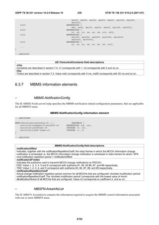
![3GPP TS 36.331 version 10.2.0 Release 10 240 ETSI TS 136 331 V10.2.0 (2011-07)
MBSFN-AreaInfoList information element
-- ASN1START
MBSFN-AreaInfoList-r9 ::= SEQUENCE (SIZE(1..maxMBSFN-Area)) OF MBSFN-AreaInfo-r9
MBSFN-AreaInfo-r9 ::= SEQUENCE {
mbsfn-AreaId-r9 INTEGER (0..255),
non-MBSFNregionLength ENUMERATED {s1, s2},
notificationIndicator-r9 INTEGER (0..7),
mcch-Config-r9 SEQUENCE {
mcch-RepetitionPeriod-r9 ENUMERATED {rf32, rf64, rf128, rf256},
mcch-Offset-r9 INTEGER (0..10),
mcch-ModificationPeriod-r9 ENUMERATED {rf512, rf1024},
sf-AllocInfo-r9 BIT STRING (SIZE(6)),
signallingMCS-r9 ENUMERATED {n2, n7, n13, n19}
},
...
}
-- ASN1STOP
MBSFN-AreaInfoList field descriptions
mbsfn-AreaId
MBSFN
Indicates the MBSFN area ID, parameter NID in TS 36.211 [21, 6.10.2.1].
mcch-ModificationPeriod
Defines periodically appearing boundaries, i.e. radio frames for which SFN mod mcch-ModificationPeriod = 0, The
contents of different transmissions of MCCH information can only be different if there is at least one such boundary in-
between them.
mcch-Offset
Indicates, together with the mcch-RepetitionPeriod, the radio frames in which MCCH is scheduled i.e. MCCH is
scheduled in radio frames for which: SFN mod mcch-RepetitionPeriod = mcch-Offset
mcch-RepetitionPeriod
Defines the interval between transmissions of MCCH information, in radio frames, Value rf32 corresponds to 32 radio
frames, rf64 corresponds to 64 radio frames and so on.
non-MBSFNregionLength
Indicates how many symbols from the beginning of the subframe constitute the non-MBSFN region. This value applies
in all subframes of the MBSFN area used for PMCH transmissions as indicated in the MSI. The values s1 and s2
correspond with 1 and 2 symbols, respectively: see TS 36.211 [21, Table 6.7-1].
notificationIndicator
Indicates which PDCCH bit is used to notify the UE about change of the MCCH applicable for this MBSFN area. Value
0 corresponds with the least significant bit as defined in TS 36.212 [22, Section 5.3.3.1] and so on.
signallingMCS
Indicates the Modulation and Coding Scheme (MCS) applicable for the subframes indicated by the field sf-AllocInfo
and for the first subframe of each MCH scheduling period (which may contain the MCH scheduling information
I
provided by MAC). Value n2 corresponds with the value 2 for parameter MCS in TS 36.213 [23, Table 7.1.7.1-1], and
so on.
sf-AllocInfo
Indicates the subframes of the radio frames indicated by the mcch-RepetitionPeriod and the mcch-Offset, that may
carry MCCH. Value “1” indicates that the corresponding subframe is allocated. The following mapping applies:
FDD: The first/ leftmost bit defines the allocation for subframe #1 of the radio frame indicated by mcch-
RepetitionPeriod and mcch-Offset, the second bit for #2, the third bit for #3 , the fourth bit for #6, the fifth bit for #7 and
the sixth bit for #8.
TDD: The first/leftmost bit defines the allocation for subframe #3 of the radio frame indicated by mcch-
RepetitionPeriod and mcch-Offset, the second bit for #4, third bit for #7, fourth bit for #8, fifth bit for #9. Uplink
subframes are not allocated. The last bit is not used.
– MBSFN-SubframeConfig
The IE MBSFN-SubframeConfig defines subframes that are reserved for MBSFN in downlink.
MBSFN-SubframeConfig information element
-- ASN1START
MBSFN-SubframeConfig ::= SEQUENCE {
radioframeAllocationPeriod ENUMERATED {n1, n2, n4, n8, n16, n32},
radioframeAllocationOffset INTEGER (0..7),
ETSI](https://image.slidesharecdn.com/ts136331v100200p-111014005410-phpapp02/85/Ts-136331v100200p-241-320.jpg)
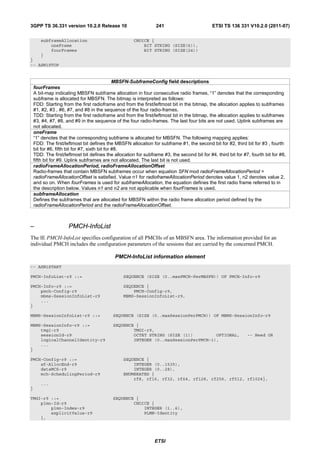
![3GPP TS 36.331 version 10.2.0 Release 10 242 ETSI TS 136 331 V10.2.0 (2011-07)
serviceId-r9 OCTET STRING (SIZE (3))
}
-- ASN1STOP
PMCH-InfoList field descriptions
dataMCS
I
Indicates the value for parameter MCS in TS 36.213 [23, Table 7.1.7.1-1], which defines the Modulation and Coding
Scheme (MCS) applicable for the subframes of this (P)MCH as indicated by the field commonSF-Alloc. The MCS
does however neither apply to the subframes that may carry MCCH i.e. the subframes indicated by the field sf-
AllocInfo within SystemInformationBlockType13 nor for the first subframe of each MCH scheduling period (which may
contain the MCH scheduling information provided by MAC).
mch-SchedulingPeriod
Indicates the MCH scheduling period i.e. the periodicity used for providing MCH scheduling information at lower layers
(MAC) applicable for an MCH. Value rf8 corresponds to 8 radio frames, rf16 corresponds to 16 radio frames and so
on. The mch-SchedulingPeriod starts in the radio frames for which: SFN mod mch-SchedulingPeriod = 0.
plmn-Index
Index of the entry in field plmn-IdentityList within SystemInformationBlockType1.
sessionId
Indicates the optional MBMS Session Identity, which together with TMGI identifies a transmission or a possible
retransmission of a specific MBMS session: see TS 29.061 [51, Sections 20.5, 17.7.11, 17.7.15]. The field is included
whenever upper layers have assigned a session identity i.e. one is available for the MBMS session in E-UTRAN.
sessionId
Identifies the identity of a session of an MBMS service.
serviceId
Uniquely identifies the identity of an MBMS service within a PLMN. The field contains octet 3- 5 of the IE Temporary
Mobile Group Identity (TMGI) as defined in TS 24.008 [49]. The first octet contains the third octet of the TMGI, the
second octet contains the fourth octet of the TMGI and so on.
sf-AllocEnd
Indicates the last subframe allocated to this (P)MCH within a period identified by field commonSF-AllocPeriod. The
th
subframes allocated to (P)MCH corresponding with the n entry in pmch-InfoList are the subsequent subframes
th
starting from either the subframe identified by sf-AllocEnd of the (n-1) listed (P)MCH or, for n=1, the first subframe,
th
through the subframe identified by sf-AllocEnd of the n listed (P)MCH. Value 0 corresponds with the first subframe
defined by field commonSF-Alloc.
6.4 RRC multiplicity and type constraint values
– Multiplicity and type constraint definitions
-- ASN1START
maxBandComb-r10 INTEGER ::= 128 -- Maximum number of band combinations.
maxBands INTEGER ::= 64 -- Maximum number of bands listed in EUTRA UE caps
maxBandwidthClass-r10 INTEGER ::= 16 -- Maximum number of supported CA BW classes per band
maxCDMA-BandClass INTEGER ::= 32 -- Maximum value of the CDMA band classes
maxCellBlack INTEGER ::= 16 -- Maximum number of blacklisted physical cell identity
-- ranges listed in SIB type 4 and 5
maxCellInfoGERAN-r9 INTEGER ::= 32 -- Maximum number of GERAN cells for which system in-
-- formation can be provided as redirection assistance
maxCellInfoUTRA-r9 INTEGER ::= 16 -- Maximum number of UTRA cells for which system
-- information can be provided as redirection
-- assistance
maxFreqUTRA-TDD-r10 INTEGER ::= 6 -- Maximum number of UTRA TDD carrier frequencies for
-- which system information can be provided as
-- redirection assistance
maxCellInter INTEGER ::= 16 -- Maximum number of neighbouring inter-frequency
-- cells listed in SIB type 5
maxCellIntra INTEGER ::= 16 -- Maximum number of neighbouring intra-frequency
-- cells listed in SIB type 4
maxCellListGERAN INTEGER ::= 3 -- Maximum number of lists of GERAN cells
maxCellMeas INTEGER ::= 32 -- Maximum number of entries in each of the
-- cell lists in a measurement object
maxCellReport INTEGER ::= 8 -- Maximum number of reported cells
maxDRB INTEGER ::= 11 -- Maximum number of Data Radio Bearers
maxEARFCN INTEGER ::= 65535 -- Maximum value of EUTRA carrier fequency
ETSI](https://image.slidesharecdn.com/ts136331v100200p-111014005410-phpapp02/85/Ts-136331v100200p-243-320.jpg)
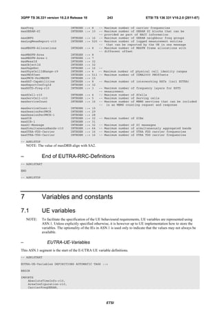
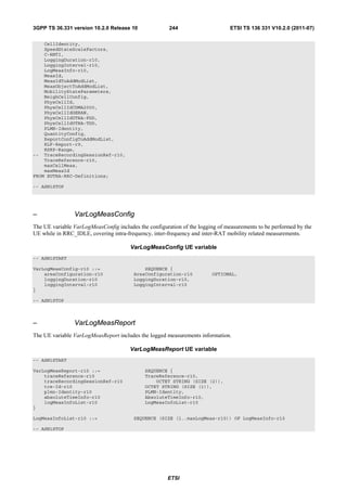
![3GPP TS 36.331 version 10.2.0 Release 10 248 ETSI TS 136 331 V10.2.0 (2011-07)
Timer Start Stop At expiry
T321 Upon receiving Upon acquiring the information Initiate the measurement
measConfig including a needed to set all fields of reporting procedure, stop
reportConfig with the cellGlobalId for the requested performing the related
purpose set to reportCGI cell, upon receiving measConfig measurements and remove the
that includes removal of the corresponding measId
reportConfig with the purpose
set to reportCGI
T330 Upon receiving Upon log volume exceeding the Perform the actions specified in
LoggedMeasurementCon suitable UE memory, upon 5.6.6.4
figuration message initiating the release of
LoggedMeasurementConfigurati
on procedure
7.4 Constants
Constant Usage
N310 Maximum number of consecutive "out-of-sync" indications received from lower layers
N311 Maximum number of consecutive "in-sync" indications received from lower layers
8 Protocol data unit abstract syntax
8.1 General
The RRC PDU contents in clause 6 and clause 10 are described using abstract syntax notation one (ASN.1) as specified
in ITU-T Rec. X.680 [13] and X.681 [14]. Transfer syntax for RRC PDUs is derived from their ASN.1 definitions by
use of Packed Encoding Rules, unaligned as specified in ITU-T Rec. X.691 [15].
The following encoding rules apply in addition to what has been specified in X.691:
- When a bit string value is placed in a bit-field as specified in 15.6 to 15.11 in X.691, the leading bit of the bit
string value shall be placed in the leading bit of the bit-field, and the trailing bit of the bit string value shall be
placed in the trailing bit of the bit-field.
NOTE: The terms 'leading bit' and 'trailing bit' are defined in ITU-T Rec. X.680. When using the 'bstring'
notation, the leading bit of the bit string value is on the left, and the trailing bit of the bit string value is on
the right.
- When decoding types constrained with the ASN.1 Contents Constraint ("CONTAINING"), automatic decoding
of the contained type should not be performed because errors in the decoding of the contained type should not
cause the decoding of the entire RRC message PDU to fail. It is recommended that the decoder first decodes the
outer PDU type that contains the OCTET STRING or BIT STRING with the Contents Constraint, and then
decodes the contained type that is nested within the OCTET STRING or BIT STRING as a separate step.
- When decoding a) RRC message PDUs, b) BIT STRING constrained with a Contents Constraint, or c) OCTET
STRING constrained with a Contents Constraint, PER decoders are required to never report an error if there are
extraneous zero or non-zero bits at the end of the encoded RRC message PDU, BIT STRING or OCTET
STRING.
8.2 Structure of encoded RRC messages
An RRC PDU, which is the bit string that is exchanged between peer entities/ across the radio interface contains the
basic production as defined in X.691.
RRC PDUs shall be mapped to and from PDCP SDUs (in case of DCCH) or RLC SDUs (in case of PCCH, BCCH,
CCCH or MCCH) upon transmission and reception as follows:
ETSI](https://image.slidesharecdn.com/ts136331v100200p-111014005410-phpapp02/85/Ts-136331v100200p-249-320.jpg)
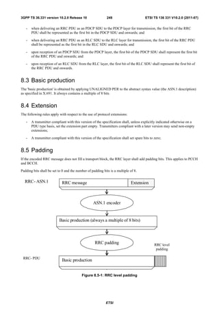
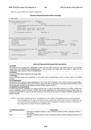
![3GPP TS 36.331 version 10.2.0 Release 10 256 ETSI TS 136 331 V10.2.0 (2011-07)
– UERadioAccessCapabilityInformation
This message is used to transfer UE radio access capability information, covering both upload to and download from the
EPC.
Direction: eNB to/ from EPC
UERadioAccessCapabilityInformation message
-- ASN1START
UERadioAccessCapabilityInformation ::= SEQUENCE {
criticalExtensions CHOICE {
c1 CHOICE{
ueRadioAccessCapabilityInformation-r8
UERadioAccessCapabilityInformation-r8-IEs,
spare7 NULL,
spare6 NULL, spare5 NULL, spare4 NULL,
spare3 NULL, spare2 NULL, spare1 NULL
},
criticalExtensionsFuture SEQUENCE {}
}
}
UERadioAccessCapabilityInformation-r8-IEs ::= SEQUENCE {
ue-RadioAccessCapabilityInfo OCTET STRING (CONTAINING UECapabilityInformation),
nonCriticalExtension SEQUENCE {} OPTIONAL
}
-- ASN1STOP
UERadioAccessCapabilityInformation field descriptions
ue-RadioAccessCapabilityInfo
Including E-UTRA, GERAN, and CDMA2000-1xRTT Bandclass radio access capabilities (separated). UTRA radio
access capabilities are not included.
10.3 Inter-node RRC information element definitions
– AS-Config
The AS-Config IE contains information about RRC configuration information in the source eNB which can be utilized
by target eNB to determine the need to change the RRC configuration during the handover preparation phase. The
information can also be used after the handover is successfully performed or during the RRC connection re-
establishment.
AS-Config information element
-- ASN1START
AS-Config ::= SEQUENCE {
sourceMeasConfig MeasConfig,
sourceRadioResourceConfig RadioResourceConfigDedicated,
sourceSecurityAlgorithmConfig SecurityAlgorithmConfig,
sourceUE-Identity C-RNTI,
sourceMasterInformationBlock MasterInformationBlock,
sourceSystemInformationBlockType1 SystemInformationBlockType1(WITH COMPONENTS
{..., nonCriticalExtension ABSENT}),
sourceSystemInformationBlockType2 SystemInformationBlockType2,
antennaInfoCommon AntennaInfoCommon,
sourceDl-CarrierFreq ARFCN-ValueEUTRA,
...,
[[ sourceSystemInformationBlockType1Ext OCTET STRING (CONTAINING
SystemInformationBlockType1-v890-IEs) OPTIONAL,
sourceOtherConfig-r9 OtherConfig-r9
]],
[[ sourceSCellConfigList-r10 SCellToAddModList-r10 OPTIONAL
]]
}
ETSI](https://image.slidesharecdn.com/ts136331v100200p-111014005410-phpapp02/85/Ts-136331v100200p-257-320.jpg)
![3GPP TS 36.331 version 10.2.0 Release 10 257 ETSI TS 136 331 V10.2.0 (2011-07)
-- ASN1STOP
NOTE: The AS-Config re-uses information elements primarily created to cover the radio interface signalling
requirements. Consequently, the information elements may include some parameters that are not relevant
for the target eNB e.g. the SFN as included in the MasterInformationBlock.
AS-Config field descriptions
antennaInfoCommon
This field provides information about the number of antenna ports in the source PCell.
sourceDL-CarrierFreq
Provides the parameter Downlink EARFCN in the source PCell, see TS 36.101 [42].
sourceOtherConfig
Provides other configuration in the source PCell.
sourceMasterInformationBlock
MasterInformationBlock transmitted in the source PCell.
sourceMeasConfig
Measurement configuration in the source cell. The measurement configuration for all measurements existing in the
source eNB when handover is triggered shall be included. See 10.5.
sourceRadioResourceConfig
Radio configuration in the source PCell. The radio resource configuration for all radio bearers existing in the source
PCell when handover is triggered shall be included. See 10.5.
sourceSCellConfigList
Radio resource configuration (common and dedicated) of the SCells configured in the source eNB.
sourceSecurityAlgorithmConfig
This field provides the AS integrity protection (SRBs) and AS ciphering (SRBs and DRBs) algorithm configuration used
in the source PCell.
sourceSystemInformationBlockType1
SystemInformationBlockType1 transmitted in the source PCell.
sourceSystemInformationBlockType2
SystemInformationBlockType2 transmitted in the source PCell.
– AS-Context
The IE AS-Context is used to transfer local E-UTRAN context required by the target eNB.
AS-Context information element
-- ASN1START
AS-Context ::= SEQUENCE {
reestablishmentInfo ReestablishmentInfo OPTIONAL -- Cond HO
}
-- ASN1STOP
AS-Context field descriptions
reestablishmentInfo
Including information needed for the RRC connection re-establishment.
Conditional presence Explanation
HO The field is mandatory present in case of handover within E-UTRA; otherwise the field is
not present.
ETSI](https://image.slidesharecdn.com/ts136331v100200p-111014005410-phpapp02/85/Ts-136331v100200p-258-320.jpg)
![3GPP TS 36.331 version 10.2.0 Release 10 258 ETSI TS 136 331 V10.2.0 (2011-07)
– ReestablishmentInfo
The ReestablishmentInfo IE contains information needed for the RRC connection re-establishment.
ReestablishmentInfo information element
-- ASN1START
ReestablishmentInfo ::= SEQUENCE {
sourcePhysCellId PhysCellId,
targetCellShortMAC-I ShortMAC-I,
additionalReestabInfoList AdditionalReestabInfoList OPTIONAL,
...
}
AdditionalReestabInfoList ::= SEQUENCE ( SIZE (1..maxReestabInfo) ) OF AdditionalReestabInfo
AdditionalReestabInfo ::= SEQUENCE{
cellIdentity CellIdentity,
key-eNodeB-Star Key-eNodeB-Star,
shortMAC-I ShortMAC-I
}
Key-eNodeB-Star ::= BIT STRING (SIZE (256))
-- ASN1STOP
ReestablishmentInfo field descriptions
additionalReestabInfoList
Contains a list of shortMAC-I and KeNB* for cells under control of the target eNB, required for potential re-
establishment by the UE in these cells to succeed.
Key-eNodeB-Star
Parameter KeNB*: See TS 33.401 [32, 7.2.8.4]. This parameter is only used for X2 handover, and for S1 handover, it
shall be ignored by target eNB.
sourcePhyCellId
The physical cell identity of the source PCell, used to determine the UE context in the target eNB at re-establishment.
targetCellShortMAC-I
The ShortMAC-I for the handover target PCell, in order for potential re-establishment to succeed.
– RRM-Config
The RRM-Config IE contains information about UE specific RRM information before the handover which can be
utilized by target eNB.
RRM-Config information element
-- ASN1START
RRM-Config ::= SEQUENCE {
ue-InactiveTime ENUMERATED {
s1, s2, s3, s5, s7, s10, s15, s20,
s25, s30, s40, s50, min1, min1s20c, min1s40,
min2, min2s30, min3, min3s30, min4, min5, min6,
min7, min8, min9, min10, min12, min14, min17, min20,
min24, min28, min33, min38, min44, min50, hr1,
hr1min30, hr2, hr2min30, hr3, hr3min30, hr4, hr5, hr6,
hr8, hr10, hr13, hr16, hr20, day1, day1hr12, day2,
day2hr12, day3, day4, day5, day7, day10, day14, day19,
day24, day30, dayMoreThan30} OPTIONAL,
...,
[[ candidateCellInfoList-r10 CandidateCellInfoList-r10 OPTIONAL
]]
}
CandidateCellInfoList-r10 ::= SEQUENCE (SIZE (1..maxFreq)) OF CandidateCellInfo-r10
CandidateCellInfo-r10 ::= SEQUENCE {
-- cellIdentification
physCellId-r10 PhysCellId,
dl-CarrierFreq-r10 ARFCN-ValueEUTRA,
ETSI](https://image.slidesharecdn.com/ts136331v100200p-111014005410-phpapp02/85/Ts-136331v100200p-259-320.jpg)
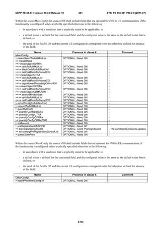
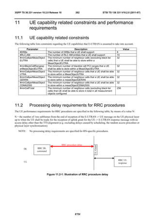
![3GPP TS 36.331 version 10.2.0 Release 10 263 ETSI TS 136 331 V10.2.0 (2011-07)
Procedure title: E-UTRAN -> UE UE -> E-UTRAN N Notes
RRC Connection Control Procedures
RRC connection RRCConnectionSetu RRCConnectionSetupCo 15
establishment p mplete
RRC connection RRCConnectionRele NA
release ase
RRC connection re- RRCConnectionReco RRCConnectionReconfigu 15
configuration (radio nfiguration rationComplete
resource configuration)
RRC connection re- RRCConnectionReco RRCConnectionReconfigu 15
configuration nfiguration rationComplete
(measurement
configuration)
RRC connection re- RRCConnectionReco RRCConnectionReconfigu 15
configuration (intra- nfiguration rationComplete
LTE mobility)
RRC connection re- RRCConnectionRees RRCConnectionReestabli 15
establishment tablishment shmentComplete
Initial security SecurityModeComma SecurityModeCommandC 10
activation nd omplete/SecurityModeCo
mmandFailure
Initial security SecurityModeComma RRCConnectionReconfigu 20 The two DL messages are
activation + RRC nd, rationComplete transmitted in the same TTI
connection re- RRCConnectionReco
configuration (RB nfiguration
establishment)
Paging Paging NA
Inter RAT mobility
Handover to E-UTRA RRCConnectionReco RRCConnectionReconfigu NA The performance of this
nfiguration (sent by rationComplete procedure is specified in
other RAT) [50] in case of handover
from GSM and [29], [30] in
case of handover from
UTRA.
Handover from E- MobilityFromEUTRA NA The performance of this
UTRA Command procedure is specified in
[16]
Handover from E- HandoverFromEUTR NA Used to trigger the
UTRA to CDMA2000 APreparationRequest handover preparation
(CDMA2000) procedure with a
CDMA2000 RAT.
The performance of this
procedure is specified in
[16]
Measurement procedures
Measurement MeasurementReport NA
Reporting
Other procedures
UE capability transfer UECapabilityEnquiry UECapabilityInformation 10
Counter check CounterCheck CounterCheckResponse 10
Proximity indication ProximityIndication NA
UE information UEInformationReque UEInformationResponse 15
st
MBMS counting MBMSCountingRequ MBMSCountingResponse NA
est
ETSI](https://image.slidesharecdn.com/ts136331v100200p-111014005410-phpapp02/85/Ts-136331v100200p-264-320.jpg)

![3GPP TS 36.331 version 10.2.0 Release 10 265 ETSI TS 136 331 V10.2.0 (2011-07)
Annex A (informative):
Guidelines, mainly on use of ASN.1
Editor's note No agreements have been reached concerning the extension of RRC PDUs so far. Any statements in
this section about the protocol extension mechanism should be considered as FFS.
A.1 Introduction
The following clauses contain guidelines for the specification of RRC protocol data units (PDUs) with ASN.1.
A.2 Procedural specification
A.2.1 General principles
The procedural specification provides an overall high level description regarding the UE behaviour in a particular
scenario.
It should be noted that most of the UE behaviour associated with the reception of a particular field is covered by the
applicable parts of the PDU specification. The procedural specification may also include specific details of the UE
behaviour upon reception of a field, but typically this should be done only for cases that are not easy to capture in the
PDU section e.g. general actions, more complicated actions depending on the value of multiple fields.
Likewise, the procedural specification need not specify the UE requirements regarding the setting of fields within the
messages that are send to E-UTRAN i.e. this may also be covered by the PDU specification.
A.2.2 More detailed aspects
The following more detailed conventions should be used:
- Bullets:
- Capitals should be used in the same manner as in other parts of the procedural text i.e. in most cases no
capital applies since the bullets are part of the sentence starting with 'The UE shall:'
- All bullets, including the last one in a sub-clause, should end with a semi-colon i.e. an ';'
- Conditions
- Whenever multiple conditions apply, a semi-colon should be used at the end of each conditions with the
exception of the last one, i.e. as in 'if cond1; or cond2:
A.3 PDU specification
A.3.1 General principles
A.3.1.1 ASN.1 sections
The RRC PDU contents are formally and completely described using abstract syntax notation (ASN.1), see X.680 [13],
X.681 (02/2002) [14].
The complete ASN.1 code is divided into a number of ASN.1 sections in the specifications. In order to facilitate the
extraction of the complete ASN.1 code from the specification, each ASN.1 section begins with a text paragraph
consisting entirely of an ASN.1 start tag, which consists of a double hyphen followed by a single space and the text
string "ASN1START" (in all upper case letters). Each ASN.1 section ends with a text paragraph consisting entirely of
ETSI](https://image.slidesharecdn.com/ts136331v100200p-111014005410-phpapp02/85/Ts-136331v100200p-266-320.jpg)
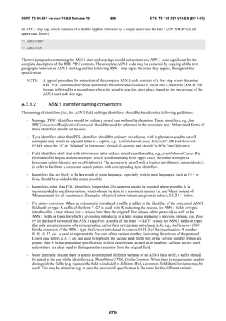
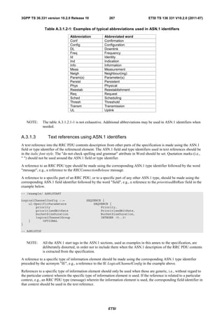
![3GPP TS 36.331 version 10.2.0 Release 10 275 ETSI TS 136 331 V10.2.0 (2011-07)
- The extension fields introduced (or frozen) in a specific version of the specification are grouped together
using double brackets.
- Extension markers within ENUMERATED
- Spare values are used until the number of values reaches the next power of 2, while the extension marker
caters for extension beyond that limit
- A suffix of the form "vXYZ" is used for the identifier of each new value, e.g. "value-vXYZ".
- Extension markers within CHOICE:
- Extension markers are introduced when extension is foreseen and when comprehension is not required by the
receiver i.e. behaviour is defined for the case where the receiver cannot comprehend the extended value (e.g.
ignoring an optional CHOICE field). It should be noted that defining the behaviour of a receiver upon
receiving a not comprehended choice value is not required if the sender is aware whether or not the receiver
supports the extended value.
- A suffix of the form "vXYZ" is used for the identifier of each new choice value, e.g. "choice-vXYZ".
Non-critical extensions at the end of a message/ of a field contained in an OCTET or BIT STRING:
- When a nonCriticalExtension is actually used, a "Need" statement is not provided for the field, which always is a
group including at least one extension and a field facilitating further possible extensions.
Further, more general, guidelines:
- In case a need statement is not provided for a group, a "Need" statement is provided for all individual extension
fields within the group i.e. including for fields that are not marked as OPTIONAL. The latter is to clarify the
action upon absence of the whole group.
A.4.3.3 Typical example of evolution of IE with local extensions
The following example illustrates the use of the extension marker for a number of elementary cases (sequence,
enumerated, choice). The example also illustrates how the IE may be revised in case the critical extension mechanism is
used.
NOTE In case there is a need to support further extensions of release n while the ASN.1 of release (n+1) has
been frozen, without requiring the release n receiver to support decoding of release (n+1) extensions,
more advanced mechanisms are needed e.g. including multiple extension markers.
-- /example/ ASN1START
InformationElement1 ::= SEQUENCE {
field1 ENUMERATED {
value1, value2, value3, value4-v880,
..., value5-v960 },
field2 CHOICE {
field2a BOOLEAN,
field2b InformationElement2b,
...,
field2c-v960 InformationElement2c-r9
},
...,
[[ field3-r9 InformationElement3-r9 OPTIONAL -- Need OR
]],
[[ field3-v9a0 InformationElement3-v9a0 OPTIONAL, -- Need OR
field4-r9 InformationElement4 OPTIONAL -- Need OR
]]
}
InformationElement1-r10 ::= SEQUENCE {
field1 ENUMERATED {
value1, value2, value3, value4-v880,
value5-v960, value6-v1170, spare2, spare1, ... },
field2 CHOICE {
field2a BOOLEAN,
field2b InformationElement2b,
field2c-v960 InformationElement2c-r9,
...,
ETSI](https://image.slidesharecdn.com/ts136331v100200p-111014005410-phpapp02/85/Ts-136331v100200p-276-320.jpg)
![3GPP TS 36.331 version 10.2.0 Release 10 276 ETSI TS 136 331 V10.2.0 (2011-07)
field2d-v12b0 INTEGER (0..63)
},
field3-r9 InformationElement3-r10 OPTIONAL, -- Need OR
field4-r9 InformationElement4 OPTIONAL, -- Need OR
field5-r10 BOOLEAN,
field6-r10 InformationElement6-r10 OPTIONAL, -- Need OR
...,
[[ field3-v1170 InformationElement3-v1170 OPTIONAL -- Need OR
]]
}
-- ASN1STOP
Some remarks regarding the extensions of InformationElement1 as shown in the above example:
– The InformationElement1 is initially extended with a number of non-critical extensions. In release 10 however, a
critical extension is introduced for the message using this IE. Consequently, a new version of the IE
InformationElement1 (i.e. InformationElement1-r10) is defined in which the earlier non-critical extensions are
incorporated by means of a revision of the original field.
– The value4-v880 is replacing a spare value defined in the original protocol version for field1. Likewise value6-
v1170 replaces spare3 that was originally defined in the r10 version of field1
– Within the critically extended release 10 version of InformationElement1, the names of the original fields/ IEs
are not changed, unless there is a real need to distinguish them from other fields/ IEs. E.g. the field1 and
InformationElement4 were defined in the original protocol version (release 8) and hence not tagged. Moreover,
the field3-r9 is introduced in release 9 and not re-tagged; although, the InformationElement3 is also critically
extended and therefore tagged InformationElement3-r10 in the release 10 version of InformationElement1.
A.4.3.4 Typical examples of non critical extension at the end of a message
The following example illustrates the use of non-critical extensions at the end of the message or at the end of a field that
is contained in a BIT or OCTET STRING i.e. when an empty sequence is used.
-- /example/ ASN1START
RRCMessage-r8-IEs ::= SEQUENCE {
field1 InformationElement1,
field2 InformationElement2,
field3 InformationElement3 OPTIONAL, -- Need ON
nonCriticalExtension RRCMessage-v860-IEs OPTIONAL
}
RRCMessage-v860-IEs ::= SEQUENCE {
field4-v860 InformationElement4 OPTIONAL, -- Need OP
field5-v860 BOOLEAN OPTIONAL, -- Cond C54
nonCriticalExtension RRCMessage-v940-IEs
}
RRCMessage-v940-IEs ::= SEQUENCE {
field6-v940 InformationElement6-r9 OPTIONAL, -- Need OR
nonCriticalExtensions SEQUENCE {} OPTIONAL -- Need OP
}
-- ASN1STOP
Some remarks regarding the extensions shown in the above example:
– The InformationElement4 is introduced in the original version of the protocol (release 8) and hence no suffix is
used.
A.4.3.5 Examples of non-critical extensions not placed at the default extension
location
The following example illustrates the use of non-critical extensions in case an extension is not placed at the default
extension location.
ETSI](https://image.slidesharecdn.com/ts136331v100200p-111014005410-phpapp02/85/Ts-136331v100200p-277-320.jpg)
![3GPP TS 36.331 version 10.2.0 Release 10 277 ETSI TS 136 331 V10.2.0 (2011-07)
– ParentIE-WithEM
The IE ParentIE-WithEM is an example of a high level IE including the extension marker (EM). The root encoding of
this IE includes two lower level IEs ChildIE1-WithoutEM and ChildIE2-WithoutEM which not include the extension
marker. Consequently, non-critical extensions of the Child-IEs have to be included at the level of the Parent-IE.
The example illustrates how the two extension IEs ChildIE1-WithoutEM-vNx0 and ChildIE2-WithoutEM-vNx0 (both in
release N) are used to connect non-critical extensions with a default extension location in the lower level IEs to the
actual extension location in this IE.
ParentIE-WithEM information element
-- /example/ ASN1START
ParentIE-WithEM ::= SEQUENCE {
-- Root encoding, including:
childIE1-WithoutEM ChildIE1-WithoutEM OPTIONAL, -- Need ON
childIE2-WithoutEM ChildIE2-WithoutEM OPTIONAL, -- Need ON
...,
[[ childIE1-WithoutEM-vNx0 ChildIE1-WithoutEM-vNx0 OPTIONAL, -- Need ON
childIE2-WithoutEM-vNx0 ChildIE2-WithoutEM-vNx0 OPTIONAL -- Need ON
]]
}
-- ASN1STOP
Some remarks regarding the extensions shown in the above example:
– The fields childIEx-WithoutEM-vNx0 may not really need to be optional (depends on what is defined at the next
lower level).
– In general, especially when there are several nesting levels, fields should be marked as optional only when there
is a clear reason.
– ChildIE1-WithoutEM
The IE ChildIE1-WithoutEM is an example of a lower level IE, used to control certain radio configurations including a
configurable feature which can be setup or released using the local IE ChIE1-ConfigurableFeature. The example
illustrates how the new field chIE1-NewField is added in release N to the configuration of the configurable feature. The
example is based on the following assumptions:
– when initially configuring as well as when modifying the new field, the original fields of the configurable feature
have to be provided also i.e. as if the extended ones were present within the setup branch of this feature.
– when the configurable feature is released, the new field should be released also.
– when omitting the original fields of the configurable feature the UE continues using the existing values (which is
used to optimise the signalling for features that typically continue unchanged upon handover).
– when omitting the new field of the configurable feature the UE releases the existing values and discontinues the
associated functionality (which may be used to support release of unsupported functionality upon handover to an
eNB supporting an earlier protocol version).
The above assumptions, which affect the use of conditions and need codes, may not always apply. Hence, the example
should not be re-used blindly.
ChildIE1-WithoutEM information elements
-- /example/ ASN1START
ChildIE1-WithoutEM ::= SEQUENCE {
-- Root encoding, including:
chIE1-ConfigurableFeature ChIE1-ConfigurableFeature OPTIONAL -- Need ON
}
ETSI](https://image.slidesharecdn.com/ts136331v100200p-111014005410-phpapp02/85/Ts-136331v100200p-278-320.jpg)
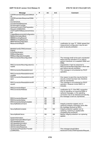
![3GPP TS 36.331 version 10.2.0 Release 10 281 ETSI TS 136 331 V10.2.0 (2011-07)
Message P A-I A-C Comment
ULInformationTransfer + - -
A.7 Miscellaneous
The following miscellaneous conventions should be used:
- References: Whenever another specification is referenced, the specification number and optionally the relevant
subclause, table or figure, should be indicated in addition to the pointer to the References section e.g. as follows:
'see TS 36.212 [22, 5.3.3.1.6]'.
ETSI](https://image.slidesharecdn.com/ts136331v100200p-111014005410-phpapp02/85/Ts-136331v100200p-282-320.jpg)
![3GPP TS 36.331 version 10.2.0 Release 10 282 ETSI TS 136 331 V10.2.0 (2011-07)
Annex B (normative): Release 8 AS feature handling
B.1 Feature group indicators
This annex contains the definitions of the bits in field featureGroupIndicators.
In this release of the protocol, the UE shall include the field featureGroupIndicators in the IE UE-EUTRA-Capability.
All the functionalities defined within the field featureGroupIndicators defined in Table B.1-1 are mandatory for the UE,
if the related capability (frequency band, RAT or SR-VCC) is also supported. For a specific indicator, if all
functionalities for a feature group listed in Table B.1-1 have been implemented and tested, the UE shall set the indicator
as one (1), else (i.e. if any one of the functionalities in a feature group listed in Table B.1-1, which have not been
implemented or tested), the UE shall set the indicator as zero (0).
The UE shall set all indicators that correspond to RATs not supported by the UE as zero (0).
The UE shall set all indicators, which do not have a definition in Table B.1-1, as zero (0).
If the optional field featureGroupIndicators is not included by a UE of a future release, the network may assume that all
features pertaining to the RATs supported by the UE, listed in Table B.1-1 and deployed in the network, have been
implemented and tested by the UE.
In Table B.1-1, a 'VoLTE capable UE' corresponds to a UE that is capable of the "Voice domain preference for E-
UTRAN" defined in TS 24.301 [35] being set to "IMS PS voice only", "IMS PS voice preferred, CS voice as
secondary" or "CS voice preferred, IMS PS voice as secondary".
Table B.1-1: Definitions of feature group indicators
Index of Definition Notes If indicated "Yes" the
indicator (description of the supported functionality, if feature shall be
(bit indicator set to one) implemented and
number) successfully tested for
this version of the
specification
1 - Intra-subframe frequency hopping for PUSCH
(leftmost scheduled by UL grant
bit) - DCI format 3a (TPC commands for PUCCH
and PUSCH with single bit power adjustments)
- PDSCH transmission mode 5
- Aperiodic CQI/PMI/RI reporting on PUSCH:
Mode 2-0 – UE selected subband CQI without
PMI
- Aperiodic CQI/PMI/RI reporting on PUSCH:
Mode 2-2 – UE selected subband CQI with
multiple PMI
2 - Simultaneous CQI and ACK/NACK on PUCCH,
i.e. PUCCH format 2a and 2b
- Absolute TPC command for PUSCH
- Resource allocation type 1 for PDSCH
- Periodic CQI/PMI/RI reporting on PUCCH:
Mode 2-0 – UE selected subband CQI without
PMI
- Periodic CQI/PMI/RI reporting on PUCCH:
Mode 2-1 – UE selected subband CQI with
single PMI
3 - 5bit RLC UM SN - can only be set to 1 if the Yes, if UE supports
- 7bit PDCP SN UE has set bit number 7 to VoLTE
1.
4 - Short DRX cycle - can only be set to 1 if the
UE has set bit number 5 to
1.
ETSI](https://image.slidesharecdn.com/ts136331v100200p-111014005410-phpapp02/85/Ts-136331v100200p-283-320.jpg)
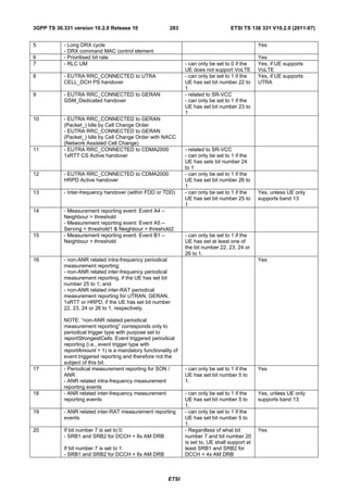
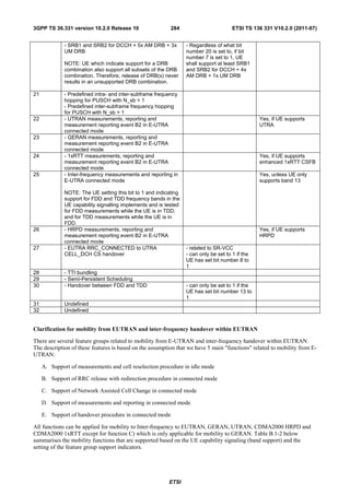
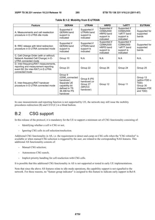
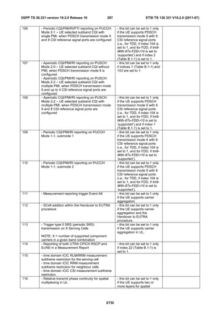

This document is a technical specification from ETSI that defines the radio resource control protocol for LTE cellular networks. It specifies aspects of the protocol such as system information acquisition, services provided to upper layers, UE states and transitions, and general requirements for procedures. The document is 3GPP TS 36.331 version 10.2.0 Release 10.


![5G Explained! A High Level Overview [Introduction]](https://cdn.slidesharecdn.com/ss_thumbnails/5gexplainedahighleveloverview-260119165306-cc137a3e-thumbnail.jpg?width=640&height=640&fit=bounds)


