Transport Layer Services, Protocols, feature, Segments
It includes introduction to transport layer services, Connection oriented and Connection less services, transport layer Protocol, TCP services, Features, Segments
Transport Layer Services, Protocols, feature, Segments
1.
Computer Network Protocol
UNIT-4Transport Layer Services
Dr. TANUJA PATGAR PhD, PostDoc
Electronics and Communication Engineering
Dr. Ambedkar Institute of Technology
Bangalore
tanujapatgar.ec@drait.edu.in
2.
The transport layeris located between the application layer and the network
layer. It provides a process-to-process communication between two
application layers, one at the local host and the other at the remote host.
Communication is provided using a logical connection, which means that the
two application layers, which can be located in different parts of the globe.
Transport-Layer Services
The transport layer is located between the network layer and the application layer.
The transport layer is responsible for providing services to the application layer; it
receives services from the network layer.
Process-to-Process Communication
The first duty of a transport-layer protocol is to provide process-to-process
communication. A process is an application-layer entity (running program) that
uses the services of the transport layer.
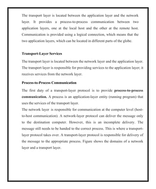
The network layer is responsible for communication at the computer level (host-
to-host communication). A network-layer protocol can deliver the message only
to the destination computer. However, this is an incomplete delivery. The
message still needs to be handed to the correct process. This is where a transport-
layer protocol takes over. A transport-layer protocol is responsible for delivery of
the message to the appropriate process. Figure shows the domains of a network
layer and a transport layer.
3.
Addressing: Port Numbers
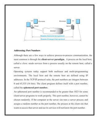
Althoughthere are a few ways to achieve process-to-process communication, the
most common is through the client-server paradigm. A process on the local host,
called a client, needs services from a process usually on the remote host, called a
server.
Operating systems today support both multiuser and multi-programming
environments. The local host and the remote host are defined using IP
addresses. In the TCP/IP protocol suite, the port numbers are integers between
0 and 65,535 (16 bits). The client program defines itself with a port number,
called the ephemeral port number.
An ephemeral port number is recommended to be greater than 1023 for some
client/server programs to work properly. This port number, however, cannot be
chosen randomly. If the computer at the server site runs a server process and
assigns a random number as the port number, the process at the client site that
wants to access that server and use its services will not know the port number.
4.
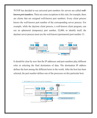
TCP/IP has decidedto use universal port numbers for servers are called well-
known port numbers. There are some exceptions to this rule; for example, there
are clients that are assigned well-known port numbers. Every client process
knows the well-known port number of the corresponding server process. For
example, while the daytime client process, a well-known client program, can
use an ephemeral (temporary) port number, 52,000, to identify itself, the
daytime server process must use the well-known (permanent) port number 13.
It should be clear by now that the IP addresses and port numbers play different
roles in selecting the final destination of data. The destination IP address
defines the host among the different hosts in the world. After the host has been
selected, the port number defines one of the processes on this particular host.
5.
49,152 65,535
0 1023
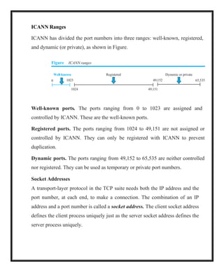
ICANNRanges
ICANN has divided the port numbers into three ranges: well-known, registered,
and dynamic (or private), as shown in Figure.
Figure ICANN ranges
Well-known Registered Dynamic or private
1024 49,151
Well-known ports. The ports ranging from 0 to 1023 are assigned and
controlled by ICANN. These are the well-known ports.
Registered ports. The ports ranging from 1024 to 49,151 are not assigned or
controlled by ICANN. They can only be registered with ICANN to prevent
duplication.
Dynamic ports. The ports ranging from 49,152 to 65,535 are neither controlled
nor registered. They can be used as temporary or private port numbers.
Socket Addresses
A transport-layer protocol in the TCP suite needs both the IP address and the
port number, at each end, to make a connection. The combination of an IP
address and a port number is called a socket address. The client socket address
defines the client process uniquely just as the server socket address defines the
server process uniquely.
6.
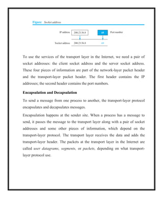
Figure Socket address
IPaddress 200.23.56.8 69 Port number
Socket address 200.23.56.8 69
To use the services of the transport layer in the Internet, we need a pair of
socket addresses: the client socket address and the server socket address.
These four pieces of information are part of the network-layer packet header
and the transport-layer packet header. The first header contains the IP
addresses; the second header contains the port numbers.
Encapsulation and Decapsulation
To send a message from one process to another, the transport-layer protocol
encapsulates and decapsulates messages.
Encapsulation happens at the sender site. When a process has a message to
send, it passes the message to the transport layer along with a pair of socket
addresses and some other pieces of information, which depend on the
transport-layer protocol. The transport layer receives the data and adds the
transport-layer header. The packets at the transport layer in the Internet are
called user datagrams, segments, or packets, depending on what transport-
layer protocol use.
7.
Decapsulation happens atthe receiver site. When the message arrives at the
destination transport layer, the header is dropped and the transport layer
delivers the message to the process running at the application layer. The sender
socket address is passed to the process in case it needs to respond to the
message received.
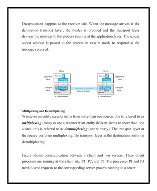
Multiplexing and Demultiplexing
Whenever an entity accepts items from more than one source, this is referred to as
multiplexing (many to one); whenever an entity delivers items to more than one
source, this is referred to as demultiplexing (one to many). The transport layer at
the source performs multiplexing; the transport layer at the destination performs
demultiplexing .
Figure shows communication between a client and two servers. Three client
processes are running at the client site, P1, P2, and P3. The processes P1 and P3
need to send requests to the corresponding server process running in a server.
8.
The client processP2 needs to send a request to the corresponding server process
running at another server. The transport layer at the client site accepts three
messages from the three processes and creates three packets. It acts as a
multiplexer.
The packets 1 and 3 use the same logical channel to reach the transport layer of
the first server. When they arrive at the server, the transport layer does the job of a
demultiplexer and distributes the messages to two different processes. The
transport layer at the second server receives packet 2 and delivers it to the
corresponding process.
Flow Control
Whenever an entity produces items and another entity consumes them, there
should be a balance between production and consumption rates. If the items are
produced faster than they can be consumed, the consumer can be overwhelmed
and may need to discard some items. If the items are produced more slowly than
they can be consumed, the consumer must wait, and the system becomes less
efficient. Flow control is related to the first issue.
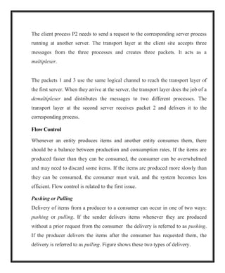
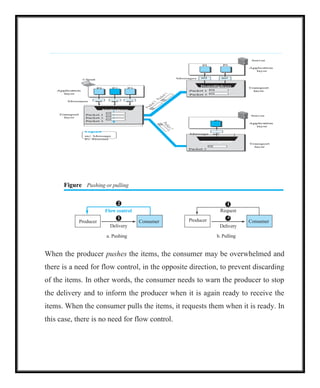
Pushing or Pulling
Delivery of items from a producer to a consumer can occur in one of two ways:
pushing or pulling. If the sender delivers items whenever they are produced
without a prior request from the consumer the delivery is referred to as pushing.
If the producer delivers the items after the consumer has requested them, the
delivery is referred to as pulling. Figure shows these two types of delivery.
9.
2
1
Consumer
Flow control
Producer
Figure Pushingor pulling
Delivery
a. Pushing b. Pulling
When the producer pushes the items, the consumer may be overwhelmed and
there is a need for flow control, in the opposite direction, to prevent discarding
of the items. In other words, the consumer needs to warn the producer to stop
the delivery and to inform the producer when it is again ready to receive the
items. When the consumer pulls the items, it requests them when it is ready. In
this case, there is no need for flow control.
1
Producer
2
Delivery
Consumer
Request
10.
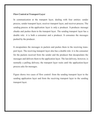
Flow Control atTransport Layer
In communication at the transport layer, dealing with four entities: sender
process, sender transport layer, receiver transport layer, and receiver process. The
sending process at the application layer is only a producer. It produces message
chunks and pushes them to the transport layer. The sending transport layer has a
double role: it is both a consumer and a producer. It consumes the messages
pushed by the producer.
It encapsulates the messages in packets and pushes them to the receiving trans-
port layer. The receiving transport layer also has a double role: it is the consumer
for the packets received from the sender and the producer that decapsulates the
messages and delivers them to the application layer. The last delivery, however, is
normally a pulling delivery; the transport layer waits until the application-layer
process asks for messages.
Figure shows two cases of flow control: from the sending transport layer to the
sending application layer and from the receiving transport layer to the sending
transport layer.
11.
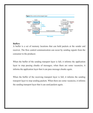
Buffers
A buffer isa set of memory locations that can hold packets at the sender and
receiver. The flow control communication can occur by sending signals from the
consumer to the producer.
When the buffer of the sending transport layer is full, it informs the application
layer to stop passing chunks of messages; when there are some vacancies, it
informs the application layer that it can pass message chunks again.
When the buffer of the receiving transport layer is full, it informs the sending
transport layer to stop sending packets. When there are some vacancies, it informs
the sending transport layer that it can send packets again.
12.
Packets
Error control
Transport
layer
Transport
layer
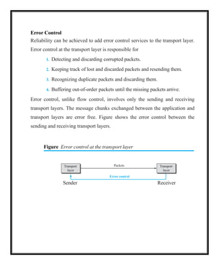
Error Control
Reliabilitycan be achieved to add error control services to the transport layer.
Error control at the transport layer is responsible for
1. Detecting and discarding corrupted packets.
2. Keeping track of lost and discarded packets and resending them.
3. Recognizing duplicate packets and discarding them.
4. Buffering out-of-order packets until the missing packets arrive.
Error control, unlike flow control, involves only the sending and receiving
transport layers. The message chunks exchanged between the application and
transport layers are error free. Figure shows the error control between the
sending and receiving transport layers.
Figure Error control at the transport layer
Sender Receiver
13.
0, 1, 2,3, 4, 5, 6, 7, 8, 9, 10, 11, 12, 13, 14, 15, 0, 1, 2, 3, 4, 5, 6, 7, 8, 9, 10, 11,
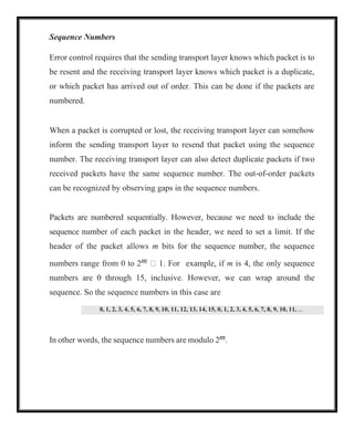
Sequence Numbers
Error control requires that the sending transport layer knows which packet is to
be resent and the receiving transport layer knows which packet is a duplicate,
or which packet has arrived out of order. This can be done if the packets are
numbered.
When a packet is corrupted or lost, the receiving transport layer can somehow
inform the sending transport layer to resend that packet using the sequence
number. The receiving transport layer can also detect duplicate packets if two
received packets have the same sequence number. The out-of-order packets
can be recognized by observing gaps in the sequence numbers.
Packets are numbered sequentially. However, because we need to include the
sequence number of each packet in the header, we need to set a limit. If the
header of the packet allows m bits for the sequence number, the sequence
numbers range from 0 to 2m 1. For example, if m is 4, the only sequence
numbers are 0 through 15, inclusive. However, we can wrap around the
sequence. So the sequence numbers in this case are
In other words, the sequence numbers are modulo 2m.
14.
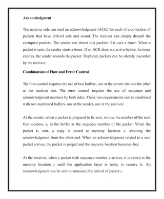
Acknowledgment
The receiver sidecan send an acknowledgment (ACK) for each of a collection of
packets that have arrived safe and sound. The receiver can simply discard the
corrupted packets. The sender can detect lost packets if it uses a timer. When a
packet is sent, the sender starts a timer. If an ACK does not arrive before the timer
expires, the sender resends the packet. Duplicate packets can be silently discarded
by the receiver.
Combination of Flow and Error Control
The flow control requires the use of two buffers, one at the sender site and the other
at the receiver site. The error control requires the use of sequence and
acknowledgment numbers by both sides. These two requirements can be combined
with two numbered buffers, one at the sender, one at the receiver.
At the sender, when a packet is prepared to be sent, we use the number of the next
free location, x, in the buffer as the sequence number of the packet. When the
packet is sent, a copy is stored at memory location x, awaiting the
acknowledgment from the other end. When an acknowledgment related to a sent
packet arrives, the packet is purged and the memory location becomes free.
At the receiver, when a packet with sequence number y arrives, it is stored at the
memory location y until the application layer is ready to receive it. An
acknowledgment can be sent to announce the arrival of packet y.
15.
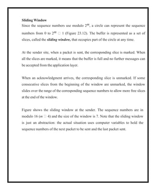
Sliding Window
Since thesequence numbers use modulo 2m, a circle can represent the sequence
numbers from 0 to 2m 1 (Figure 23.12). The buffer is represented as a set of
slices, called the sliding window, that occupies part of the circle at any time.
At the sender site, when a packet is sent, the corresponding slice is marked. When
all the slices are marked, it means that the buffer is full and no further messages can
be accepted from the application layer.
When an acknowledgment arrives, the corresponding slice is unmarked. If some
consecutive slices from the beginning of the window are unmarked, the window
slides over the range of the corresponding sequence numbers to allow more free slices
at the end of the window.
Figure shows the sliding window at the sender. The sequence numbers are in
modulo 16 (m 4) and the size of the window is 7. Note that the sliding window
is just an abstraction: the actual situation uses computer variables to hold the
sequence numbers of the next packet to be sent and the last packet sent.
16.
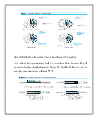
Most protocols showthe sliding window using linear representation.
Figure shows this representation. Both representations tell us the same thing. If
we take both sides of each diagram in Figure 23.13 and bend them up, we can
make the same diagram as in Figure 23.12.
17.
17
Congestion Control
Congestion ina network may occur if the load on the network—the number of
packets sent to the network—is greater than the capacity of the network—the
number of packets a network can handle.
Congestion control refers to the mechanisms and techniques that control the
congestion and keep the load below the capacity. Congestion happens in any
system that involves waiting.
Congestion in a network or internetwork occurs because routers and switches
have queues—buffers that hold the packets before and after processing. A router,
for example, has an input queue and an output queue for each interface. If a router
cannot process the packets at the same rate at which they arrive, the queues
become overloaded and congestion occurs.
Connectionless and Connection-Oriented Protocols
A transport-layer protocol, like a network-layer protocol, can provide two types
of services: connectionless and connection-oriented. The nature of these services
at the transport layer, however, is different from the ones at the network layer.
Connectionless service at the transport layer means independency between
packets; connection-oriented means dependency.
18.
18
Connectionless Service
In aconnectionless service, the source process (application program) needs to
divide its message into chunks of data of the size acceptable by the transport layer
and deliver them to the transport layer one by one.
The transport layer treats each chunk as a single unit without any relation between
the chunks.
When a chunk arrives from the application layer, the transport layer encapsulates
it in a packet and sends it. To show the independency of packets, assume that a
client process has three chunks of messages to send to a server process. The
chunks are handed over to the connectionless transport protocol in order.
However, since there is no dependency between the packets at the transport layer,
the packets may arrive out of order at the destination and will be delivered out of
order to the server process .
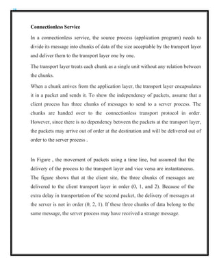
In Figure , the movement of packets using a time line, but assumed that the
delivery of the process to the transport layer and vice versa are instantaneous.
The figure shows that at the client site, the three chunks of messages are
delivered to the client transport layer in order (0, 1, and 2). Because of the
extra delay in transportation of the second packet, the delivery of messages at
the server is not in order (0, 2, 1). If these three chunks of data belong to the
same message, the server process may have received a strange message.
19.
19
The situation wouldbe worse if one of the packets were lost. Since there is no
numbering on the packets, the receiving transport layer has no idea that one of
the messages has been lost. It just delivers two chunks of data to the server
process.
The above two problems arise from the fact that the two transport layers do
not coordinate with each other. The receiving transport layer does not know
when the first packet will come nor when all of the packets have arrived.
Connection-Oriented Service
In a connection-oriented service, the client and the server first need to
establish a logical connection between themselves. The data exchange can
only happen after the connection establishment. After data exchange, the
connection needs to be torn down .
20.
20
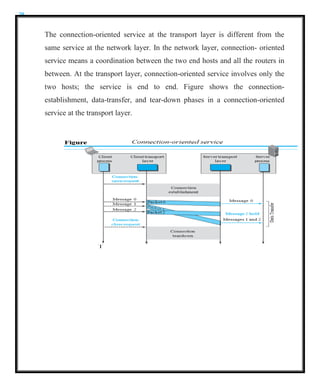
The connection-oriented serviceat the transport layer is different from the
same service at the network layer. In the network layer, connection- oriented
service means a coordination between the two end hosts and all the routers in
between. At the transport layer, connection-oriented service involves only the
two hosts; the service is end to end. Figure shows the connection-
establishment, data-transfer, and tear-down phases in a connection-oriented
service at the transport layer.
21.
21
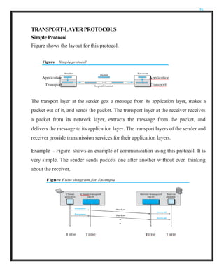
TRANSPORT-LAYER PROTOCOLS
Simple Protocol
Figureshows the layout for this protocol.
The transport layer at the sender gets a message from its application layer, makes a
packet out of it, and sends the packet. The transport layer at the receiver receives
a packet from its network layer, extracts the message from the packet, and
delivers the message to its application layer. The transport layers of the sender and
receiver provide transmission services for their application layers.
Example - Figure shows an example of communication using this protocol. It is
very simple. The sender sends packets one after another without even thinking
about the receiver.
22.
22
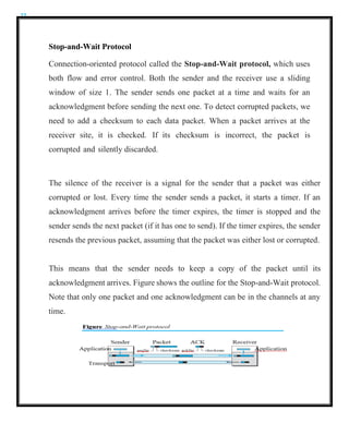
Stop-and-Wait Protocol
Connection-oriented protocolcalled the Stop-and-Wait protocol, which uses
both flow and error control. Both the sender and the receiver use a sliding
window of size 1. The sender sends one packet at a time and waits for an
acknowledgment before sending the next one. To detect corrupted packets, we
need to add a checksum to each data packet. When a packet arrives at the
receiver site, it is checked. If its checksum is incorrect, the packet is
corrupted and silently discarded.
The silence of the receiver is a signal for the sender that a packet was either
corrupted or lost. Every time the sender sends a packet, it starts a timer. If an
acknowledgment arrives before the timer expires, the timer is stopped and the
sender sends the next packet (if it has one to send). If the timer expires, the sender
resends the previous packet, assuming that the packet was either lost or corrupted.
This means that the sender needs to keep a copy of the packet until its
acknowledgment arrives. Figure shows the outline for the Stop-and-Wait protocol.
Note that only one packet and one acknowledgment can be in the channels at any
time.
23.
23
The Stop-and-Wait protocolis a connection-oriented protocol that provides flow
and error control.
Sequence Numbers
To prevent duplicate packets, the protocol uses sequence numbers and
acknowledgment numbers. A field is added to the packet header to hold the
sequence number of that packet. One important consideration is the range of the
sequence numbers. Assume we have used x as a sequence number; we only need
to use x 1 after that. There is no need for x 2. To show this, assume that the
sender has sent the packet with sequence number x. Three things can happen.
1.The packet arrives safe and sound at the receiver site; the receiver sends an
acknowledgment. The acknowledgment arrives at the sender site, causing the
sender to send the next packet numbered x 1.
2. The packet is corrupted or never arrives at the receiver site; the sender resends
the packet (numbered x) after the time-out. The receiver returns an
acknowledgment.
3. The packet arrives safe and sound at the receiver site; the receiver sends an
acknowledgment, but the acknowledgment is corrupted or lost. The sender
resends the packet (numbered x) after the time-out. Note that the packet here is a
duplicate. The receiver can recognize this fact because it expects packet x 1 but
packet x was received.
24.
24
There is aneed for sequence numbers x and x 1 because the receiver needs
to distinguish between case 1 and case 3. But there is no need for a packet to
be numbered x 2. In case 1, the packet can be numbered x again because
packets x and x 1 are acknowledged and there is no ambiguity at either site. In
cases 2 and 3, the new packet is x 1, not x 2. If only x and x 1 are needed,
we can let x 0 and x 1 1. This means that the sequence is 0, 1, 0, 1, 0, and
so on. This is referred to as modulo 2 arithmetic.
Acknowledgment Numbers
The acknowledgment numbers always announce the sequence number of the
next packet expected by the receiver. For example, if packet 0 has arrived safe
and sound, the receiver sends an ACK with acknowledgment 1 (meaning
packet 1 is expected next). If packet 1 has arrived safe and sound, the receiver
sends an ACK with acknowledgment 0 (meaning packet 0 is expected).
Efficiency
The Stop-and-Wait protocol is very inefficient if channel is thick and long. By
thick, channel has a large bandwidth (high data rate); by long, The product of
these two is called the bandwidth- delay product. Suppose the channel as a pipe.
The bandwidth-delay product then is the volume of the pipe in bits. The pipe is
always there. It is not efficient if it is not used. The bandwidth-delay product is a
measure of the number of bits a sender can transmit through the system while
waiting for an acknowledgment from the receiver.
25.
25
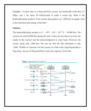
Example - Assumethat, in a Stop-and-Wait system, the bandwidth of the line is 1
Mbps, and 1 bit takes 20 milliseconds to make a round trip. What is the
bandwidth-delay product? If the system data packets are 1,000 bits in length, what
is the utilization percentage of the link?
Solution
The bandwidth-delay product is (1 106
) (20 10 3) 20,000 bits. The
system can send 20,000 bits during the time it takes for the data to go from the
sender to the receiver and the acknowledgment to come back. However, the
system sends only 1,000 bits. We can say that the link utilization is only
1,000 20,000, or 5 percent. For this reason, in a link with a high bandwidth or
long delay, the use of Stop-and-Wait wastes the capacity of the link.
26.
26
Pipelining
In networking andin other areas, a task is often begun before the previous task
has ended. This is known as pipelining. There is no pipelining in the Stop-and-
Wait protocol because a sender must wait for a packet to reach the destination and
be acknowledged before the next packet can be sent. However, pipelining does
apply to our next two protocols because several packets can be sent before a
sender receives feedback about the previous packets. Pipelining improves the
efficiency of the transmission if the number of bits in transition is large with
respect to the bandwidth- delay product.
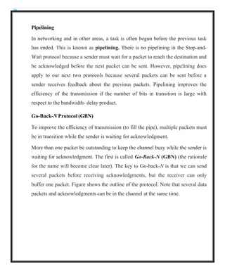
Go-Back-N Protocol (GBN)
To improve the efficiency of transmission (to fill the pipe), multiple packets must
be in transition while the sender is waiting for acknowledgment.
More than one packet be outstanding to keep the channel busy while the sender is
waiting for acknowledgment. The first is called Go-Back-N (GBN) (the rationale
for the name will become clear later). The key to Go-back-N is that we can send
several packets before receiving acknowledgments, but the receiver can only
buffer one packet. Figure shows the outline of the protocol. Note that several data
packets and acknowledgments can be in the channel at the same time.
27.
27
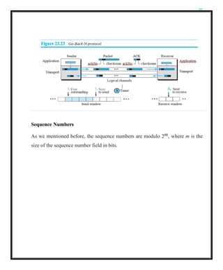
Sequence Numbers
As wementioned before, the sequence numbers are modulo 2m, where m is the
size of the sequence number field in bits.
28.
28
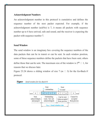
Acknowledgment Numbers
An acknowledgmentnumber in this protocol is cumulative and defines the
sequence number of the next packet expected. For example, if the
acknowledgment number (ackNo) is 7, it means all packets with sequence
number up to 6 have arrived, safe and sound, and the receiver is expecting the
packet with sequence number 7.
Send Window
The send window is an imaginary box covering the sequence numbers of the
data packets that can be in transit or can be sent. In each window position,
some of these sequence numbers define the packets that have been sent; others
define those that can be sent. The maximum size of the window is 2m 1, for
reasons that we discuss later.
Figure 23.24 shows a sliding window of size 7 (m 3) for the Go-Back-N
protocol.
29.
29
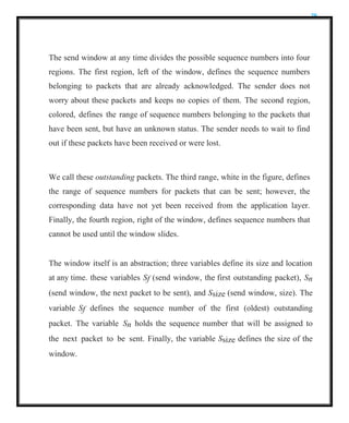
The send windowat any time divides the possible sequence numbers into four
regions. The first region, left of the window, defines the sequence numbers
belonging to packets that are already acknowledged. The sender does not
worry about these packets and keeps no copies of them. The second region,
colored, defines the range of sequence numbers belonging to the packets that
have been sent, but have an unknown status. The sender needs to wait to find
out if these packets have been received or were lost.
We call these outstanding packets. The third range, white in the figure, defines
the range of sequence numbers for packets that can be sent; however, the
corresponding data have not yet been received from the application layer.
Finally, the fourth region, right of the window, defines sequence numbers that
cannot be used until the window slides.
The window itself is an abstraction; three variables define its size and location
at any time. these variables Sf (send window, the first outstanding packet), Sn
(send window, the next packet to be sent), and Ssize (send window, size). The
variable Sf defines the sequence number of the first (oldest) outstanding
packet. The variable Sn holds the sequence number that will be assigned to
the next packet to be sent. Finally, the variable Ssize defines the size of the
window.
30.
30
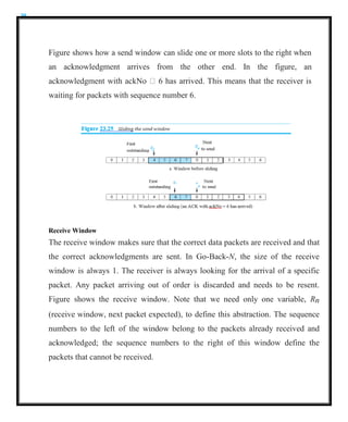
Figure shows howa send window can slide one or more slots to the right when
an acknowledgment arrives from the other end. In the figure, an
acknowledgment with ackNo 6 has arrived. This means that the receiver is
waiting for packets with sequence number 6.
Receive Window
The receive window makes sure that the correct data packets are received and that
the correct acknowledgments are sent. In Go-Back-N, the size of the receive
window is always 1. The receiver is always looking for the arrival of a specific
packet. Any packet arriving out of order is discarded and needs to be resent.
Figure shows the receive window. Note that we need only one variable, Rn
(receive window, next packet expected), to define this abstraction. The sequence
numbers to the left of the window belong to the packets already received and
acknowledged; the sequence numbers to the right of this window define the
packets that cannot be received.
31.
31
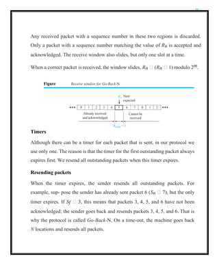
Any received packetwith a sequence number in these two regions is discarded.
Only a packet with a sequence number matching the value of Rn is accepted and
acknowledged. The receive window also slides, but only one slot at a time.
When a correct packet is received, the window slides, Rn (Rn 1) modulo 2m.
Figure Receive window for Go-Back-N
Rn
Next
Rsize = 1
Timers
Although there can be a timer for each packet that is sent, in our protocol we
use only one. The reason is that the timer for the first outstanding packet always
expires first. We resend all outstanding packets when this timer expires.
Resending packets
When the timer expires, the sender resends all outstanding packets. For
example, sup- pose the sender has already sent packet 6 (Sn 7), but the only
timer expires. If Sf 3, this means that packets 3, 4, 5, and 6 have not been
acknowledged; the sender goes back and resends packets 3, 4, 5, and 6. That is
why the protocol is called Go-Back-N. On a time-out, the machine goes back
N locations and resends all packets.
expected
0 1 2 3 4 5 6 7 0 1 2
Already received Cannot be
and acknowledged received
32.
32
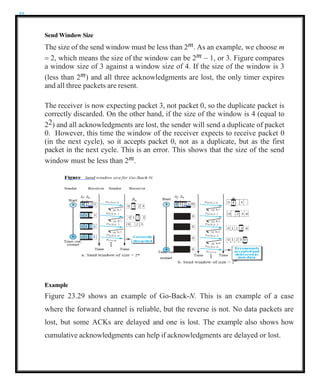
Send Window Size
Thesize of the send window must be less than 2m. As an example, we choose m
= 2, which means the size of the window can be 2m − 1, or 3. Figure compares
a window size of 3 against a window size of 4. If the size of the window is 3
(less than 2m) and all three acknowledgments are lost, the only timer expires
and all three packets are resent.
The receiver is now expecting packet 3, not packet 0, so the duplicate packet is
correctly discarded. On the other hand, if the size of the window is 4 (equal to
22) and all acknowledgments are lost, the sender will send a duplicate of packet
0. However, this time the window of the receiver expects to receive packet 0
(in the next cycle), so it accepts packet 0, not as a duplicate, but as the first
packet in the next cycle. This is an error. This shows that the size of the send
window must be less than 2m.
Example
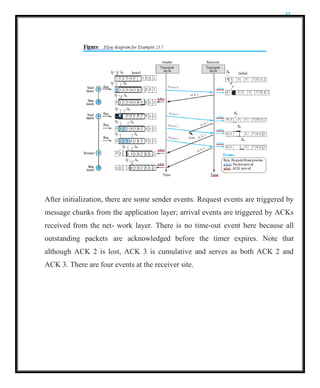
Figure 23.29 shows an example of Go-Back-N. This is an example of a case
where the forward channel is reliable, but the reverse is not. No data packets are
lost, but some ACKs are delayed and one is lost. The example also shows how
cumulative acknowledgments can help if acknowledgments are delayed or lost.
33.
33
After initialization, thereare some sender events. Request events are triggered by
message chunks from the application layer; arrival events are triggered by ACKs
received from the net- work layer. There is no time-out event here because all
outstanding packets are acknowledged before the timer expires. Note that
although ACK 2 is lost, ACK 3 is cumulative and serves as both ACK 2 and
ACK 3. There are four events at the receiver site.
34.
34
Selective-Repeat Protocol
The Go-Back-Nprotocol simplifies the process at the receiver. The receiver
keeps track of only one variable, and there is no need to buffer out-of-order
packets; they are simply discarded. However, this protocol is inefficient if the
underlying network proto- col loses a lot of packets.
Each time a single packet is lost or corrupted, the sender resends all
outstanding packets, even though some of these packets may have been
received safe and sound but out of order. If the network layer is losing many
packets because of congestion in the network, the resending of all of these
outstanding packets makes the congestion worse, and eventually more packets
are lost. This has an avalanche effect that may result in the total collapse of the
network.
Another protocol, called the Selective-Repeat (SR) protocol, has been devised,
which, as the name implies, resends only selective packets, those that are actually
lost. The outline of this protocol is shown in Figure.
35.
35
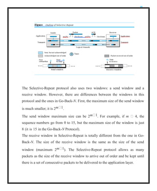
The Selective-Repeat protocolalso uses two windows: a send window and a
receive window. However, there are differences between the windows in this
protocol and the ones in Go-Back-N. First, the maximum size of the send window
is much smaller; it is 2m 1.
The send window maximum size can be 2m 1. For example, if m 4, the
sequence numbers go from 0 to 15, but the maximum size of the window is just
8 (it is 15 in the Go-Back-N Protocol).
The receive window in Selective-Repeat is totally different from the one in Go-
Back-N. The size of the receive window is the same as the size of the send
window (maximum 2m 1). The Selective-Repeat protocol allows as many
packets as the size of the receive window to arrive out of order and be kept until
there is a set of consecutive packets to be delivered to the application layer.
36.
36
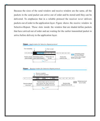
Because the sizesof the send window and receive window are the same, all the
packets in the send packet can arrive out of order and be stored until they can be
delivered. To emphasize that in a reliable protocol the receiver never delivers
packets out of order to the application layer. Figure shows the receive window in
Selective-Repeat. Those slots inside the window that are shaded define packets
that have arrived out of order and are waiting for the earlier transmitted packet to
arrive before delivery to the application layer.
37.
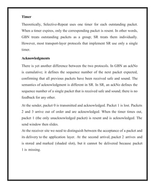
Timer
Theoretically, Selective-Repeat usesone timer for each outstanding packet.
When a timer expires, only the corresponding packet is resent. In other words,
GBN treats outstanding packets as a group; SR treats them individually.
However, most transport-layer protocols that implement SR use only a single
timer.
Acknowledgments
There is yet another difference between the two protocols. In GBN an ackNo
is cumulative; it defines the sequence number of the next packet expected,
confirming that all previous packets have been received safe and sound. The
semantics of acknowledgment is different in SR. In SR, an ackNo defines the
sequence number of a single packet that is received safe and sound; there is no
feedback for any other.
At the sender, packet 0 is transmitted and acknowledged. Packet 1 is lost. Packets
2 and 3 arrive out of order and are acknowledged. When the timer times out,
packet 1 (the only unacknowledged packet) is resent and is acknowledged. The
send window then slides.
At the receiver site we need to distinguish between the acceptance of a packet and
its delivery to the application layer. At the second arrival, packet 2 arrives and
is stored and marked (shaded slot), but it cannot be delivered because packet
1 is missing.
38.
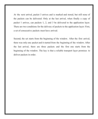
At the nextarrival, packet 3 arrives and is marked and stored, but still none of
the packets can be delivered. Only at the last arrival, when finally a copy of
packet 1 arrives, can packets 1, 2, and 3 be delivered to the application layer.
There are two conditions for the delivery of packets to the application layer: First,
a set of consecutive packets must have arrived.
Second, the set starts from the beginning of the window. After the first arrival,
there was only one packet and it started from the beginning of the window. After
the last arrival, there are three packets and the first one starts from the
beginning of the window. The key is that a reliable transport layer promises to
deliver packets in order.
39.
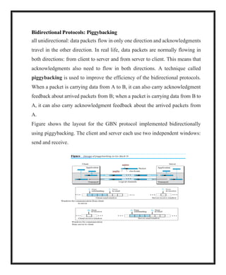
Bidirectional Protocols: Piggybacking
allunidirectional: data packets flow in only one direction and acknowledgments
travel in the other direction. In real life, data packets are normally flowing in
both directions: from client to server and from server to client. This means that
acknowledgments also need to flow in both directions. A technique called
piggybacking is used to improve the efficiency of the bidirectional protocols.
When a packet is carrying data from A to B, it can also carry acknowledgment
feedback about arrived packets from B; when a packet is carrying data from B to
A, it can also carry acknowledgment feedback about the arrived packets from
A.
Figure shows the layout for the GBN protocol implemented bidirectionally
using piggybacking. The client and server each use two independent windows:
send and receive.
40.
USER DATAGRAM PROTOCOL
TheUser Datagram Protocol (UDP) is a connectionless, unreliable transport
protocol. It does not add anything to the services of IP except for providing
process-to-process communication instead of host-to-host communication. UDP
is a very simple protocol using a minimum of overhead. If a process wants to send
a small message and does not care much about reliability, it can use UDP. Sending
a small message using UDP takes much less interaction between the sender and
receiver than using TCP.
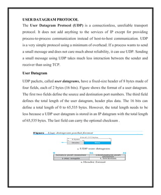
User Datagram
UDP packets, called user datagrams, have a fixed-size header of 8 bytes made of
four fields, each of 2 bytes (16 bits). Figure shows the format of a user datagram.
The first two fields define the source and destination port numbers. The third field
defines the total length of the user datagram, header plus data. The 16 bits can
define a total length of 0 to 65,535 bytes. However, the total length needs to be
less because a UDP user datagram is stored in an IP datagram with the total length
of 65,535 bytes. The last field can carry the optional checksum .
41.
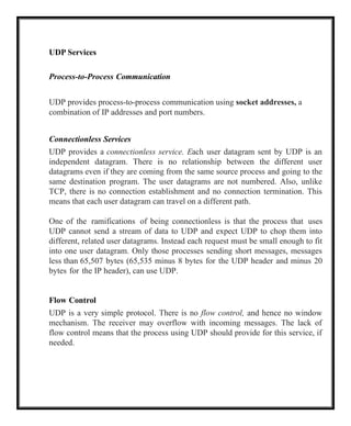
UDP Services
Process-to-Process Communication
UDPprovides process-to-process communication using socket addresses, a
combination of IP addresses and port numbers.
Connectionless Services
UDP provides a connectionless service. Each user datagram sent by UDP is an
independent datagram. There is no relationship between the different user
datagrams even if they are coming from the same source process and going to the
same destination program. The user datagrams are not numbered. Also, unlike
TCP, there is no connection establishment and no connection termination. This
means that each user datagram can travel on a different path.
One of the ramifications of being connectionless is that the process that uses
UDP cannot send a stream of data to UDP and expect UDP to chop them into
different, related user datagrams. Instead each request must be small enough to fit
into one user datagram. Only those processes sending short messages, messages
less than 65,507 bytes (65,535 minus 8 bytes for the UDP header and minus 20
bytes for the IP header), can use UDP.
Flow Control
UDP is a very simple protocol. There is no flow control, and hence no window
mechanism. The receiver may overflow with incoming messages. The lack of
flow control means that the process using UDP should provide for this service, if
needed.
42.
Error Control
There isno error control mechanism in UDP except for the checksum. This
means that the sender does not know if a message has been lost or duplicated.
When the receiver detects an error through the checksum, the user datagram is
silently discarded. The lack of error control means that the process using UDP
should provide for this service, if needed.
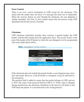
Checksum
UDP checksum calculation includes three sections: a pseudo header, the UDP
header, and the data coming from the application layer. The pseudo header is the
part of the header of the IP packet in which the user datagram is to be encapsulated
with some fields filled with 0s .
If the checksum does not include the pseudo header, a user datagram may arrive
safe and sound. However, if the IP header is corrupted, it may be delivered to
the wrong host.
The protocol field is added to ensure that the packet belongs to UDP, and not
to TCP. The value of the protocol field for UDP is 17. If this value is changed
during transmission, the checksum calculation at the receiver will detect it and
UDP drops the packet. It is not delivered to the wrong protocol.
43.
Optional Inclusion ofChecksum
The sender of a UDP packet can choose not to calculate the checksum. In this
case, the checksum field is filled with all 0s before being sent. In the situation
where the sender decides to calculate the checksum, but it happens that the
result is all 0s, the checksum is changed to all 1s before the packet is sent. In
other words, the sender complements the sum two times. Note that this does
not create confusion because the value of the checksum is never all 1s in a
normal situation
Congestion Control
Since UDP is a connectionless protocol, it does not provide congestion
control. UDP assumes that the packets sent are small and sporadic and cannot
create congestion in the network. This assumption may or may not be true
today, when UDP is used for interactive real-time transfer of audio and video.
Encapsulation and Decapsulation
To send a message from one process to another, the UDP protocol
encapsulates and decapsulates messages.
44.
Multiplexing and Demultiplexing
Ina host running a TCP/IP protocol suite, there is only one UDP but possibly
several processes that may want to use the services of UDP. To handle this
situation, UDP multiplexes and demultiplexes.
Comparison between UDP and Generic Simple Protocol
The only difference is that UDP provides an optional checksum to detect
corrupted packets at the receiver site. If the checksum is added to the packet, the
receiving UDP can check the packet and discard the packet if it is corrupted. No
feedback, however, is sent to the sender.
UDP Applications
An application designer sometimes needs to compromise to get the optimum. For
example, in our daily life, we all know that a one-day delivery of a package by a
carrier is more expensive than a three-day delivery. Although high speed and low
cost are both desirable features in delivery of a parcel, they are in conflict with
each other.
UDP Features
Connectionless Service
UDP is a connectionless protocol. Each UDP packet is independent from other
packets sent by the same application program. This feature can be considered as
an advantage or disadvantage depending on the application requirements. It is an
advantage if, for example, a client application needs to send a short request to a
server and to receive a short response.
45.
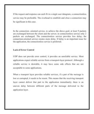
If the requestand response can each fit in a single user datagram, a connectionless
service may be preferable. The overhead to establish and close a connection may
be significant in this case.
In the connection- oriented service, to achieve the above goal, at least 9 packets
are exchanged between the client and the server; in connectionless service only 2
packets are exchanged. The connectionless service provides less delay; the
connection-oriented service creates more delay. If delay is an important issue for
the application, the connectionless service is preferred.
Lack of Error Control
UDP does not provide error control; it provides an unreliable service. Most
applications expect reliable service from a transport-layer protocol. Although a
reliable service is desirable, it may have some side effects that are not
acceptable to some applications.
When a transport layer provides reliable services, if a part of the message is
lost or corrupted, it needs to be resent. This means that the receiving transport
layer cannot deliver that part to the application immediately; there is an
uneven delay between different parts of the message delivered to the
application layer.
46.
Lack of CongestionControl
UDP does not provide congestion control. However, UDP does not create
additional traffic in an error-prone network. TCP may resend a packet
several times and thus contribute to the creation of congestion or worsen a
congested situation. Therefore, in some cases, lack of error control in UDP can
be considered an advantage when congestion is a big issue.
Typical Applications
The following shows some typical applications that can benefit more from the
services of UDP than from those of TCP.
1. UDP is suitable for a process that requires simple request-response
communication with little concern for flow and error control. It is not usually
used for a process such as FTP that needs to send bulk data .
2.UDP is suitable for a process with internal flow- and error-control mechanisms.
For example, the Trivial File Transfer Protocol (TFTP) process includes flow and
error control. It can easily use UDP.
3.UDP is a suitable transport protocol for multicasting. Multicasting capability is
embedded in the UDP software but not in the TCP software.
4.UDP is used for management processes such as SNMP
5.UDP is used for some route updating protocols such as Routing Information
Proto- col (RIP)
6.UDP is normally used for interactive real-time applications that cannot tolerate
uneven delay between sections of a received message .
47.
TRANSMISSION CONTROL PROTOCOL
Itis a connection-oriented, reliable protocol. TCP explicitly defines connection
establishment, data transfer, and connection tear- down phases to provide a
connection-oriented service. TCP uses a combination of GBN and SR protocols to
provide reliability. To achieve this goal, TCP uses checksum (for error detection),
retransmission of lost or corrupted packets, cumulative and selective
acknowledgments, and timers.
TCP Services
Process-to-Process Communication
As with UDP, TCP provides process-to-process communication using port
numbers.
Stream Delivery Service
TCP, unlike UDP, is a stream-oriented protocol. In UDP, a process sends
messages with predefined boundaries to UDP for delivery. UDP adds its own
header to each of these messages and delivers it to IP for transmission. Each
message from the process is called a user datagram, and becomes, eventually,
one IP datagram. Neither IP nor UDP recognizes any relationship between the
datagrams.
TCP, on the other hand, allows the sending process to deliver data as a stream
of bytes and allows the receiving process to obtain data as a stream of bytes.
TCP creates an environment in which the two processes seem to be connected
by an imaginary “tube” that carries their bytes across the Internet. This
imaginary environment is depicted in Figure . The sending process produces
(writes to) the stream and the receiving process consumes (reads from) it.
48.
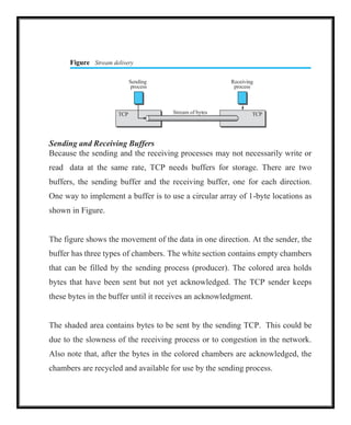
Figure Stream delivery
Sending
process
Receiving
process
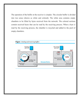
Sendingand Receiving Buffers
Because the sending and the receiving processes may not necessarily write or
read data at the same rate, TCP needs buffers for storage. There are two
buffers, the sending buffer and the receiving buffer, one for each direction.
One way to implement a buffer is to use a circular array of 1-byte locations as
shown in Figure.
The figure shows the movement of the data in one direction. At the sender, the
buffer has three types of chambers. The white section contains empty chambers
that can be filled by the sending process (producer). The colored area holds
bytes that have been sent but not yet acknowledged. The TCP sender keeps
these bytes in the buffer until it receives an acknowledgment.
The shaded area contains bytes to be sent by the sending TCP. This could be
due to the slowness of the receiving process or to congestion in the network.
Also note that, after the bytes in the colored chambers are acknowledged, the
chambers are recycled and available for use by the sending process.
TCP Stream of bytes TCP
49.
The operation ofthe buffer at the receiver is simpler. The circular buffer is divided
into two areas (shown as white and colored). The white area contains empty
chambers to be filled by bytes received from the network. The colored sections
contain received bytes that can be read by the receiving process. When a byte is
read by the receiving process, the chamber is recycled and added to the pool of
empty chambers.
50.
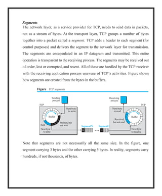
Segments
The network layer,as a service provider for TCP, needs to send data in packets,
not as a stream of bytes. At the transport layer, TCP groups a number of bytes
together into a packet called a segment. TCP adds a header to each segment (for
control purposes) and delivers the segment to the network layer for transmission.
The segments are encapsulated in an IP datagram and transmitted. This entire
operation is transparent to the receiving process. The segments may be received out
of order, lost or corrupted, and resent. All of these are handled by the TCP receiver
with the receiving application process unaware of TCP’s activities. Figure shows
how segments are created from the bytes in the buffers.
Figure TCP segments
Receiving
process
Next byte
to read
Received,
but not read
Buffer
TCP
Segment 1
H
Next byte
to receive
Note that segments are not necessarily all the same size. In the figure, one
segment carrying 3 bytes and the other carrying 5 bytes. In reality, segments carry
hundreds, if not thousands, of bytes.
Sending
process
TCP
Next byte
to write
Buffer
Sent
Next byte
to send
Written, but
not sent Segment N
H
51.
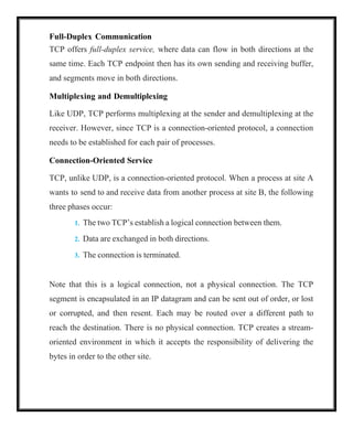
Full-Duplex Communication
TCP offersfull-duplex service, where data can flow in both directions at the
same time. Each TCP endpoint then has its own sending and receiving buffer,
and segments move in both directions.
Multiplexing and Demultiplexing
Like UDP, TCP performs multiplexing at the sender and demultiplexing at the
receiver. However, since TCP is a connection-oriented protocol, a connection
needs to be established for each pair of processes.
Connection-Oriented Service
TCP, unlike UDP, is a connection-oriented protocol. When a process at site A
wants to send to and receive data from another process at site B, the following
three phases occur:
1. The two TCP’s establish a logical connection between them.
2. Data are exchanged in both directions.
3. The connection is terminated.
Note that this is a logical connection, not a physical connection. The TCP
segment is encapsulated in an IP datagram and can be sent out of order, or lost
or corrupted, and then resent. Each may be routed over a different path to
reach the destination. There is no physical connection. TCP creates a stream-
oriented environment in which it accepts the responsibility of delivering the
bytes in order to the other site.
52.
Reliable Service
TCP isa reliable transport protocol. It uses an acknowledgment mechanism to
check the safe and sound arrival of data.
TCP Features
Numbering System
Although the TCP software keeps track of the segments being transmitted or
received, there is no field for a segment number value in the segment header.
Instead, there are two fields, called the sequence number and the
acknowledgment number. These two fields refer to a byte number and not a
segment number.
Byte Number
TCP numbers all data bytes (octets) that are transmitted in a connection.
Numbering is independent in each direction. When TCP receives bytes of data
from a process, TCP stores them in the sending buffer and numbers them. The
numbering does not necessarily start from 0. Instead, TCP chooses an arbitrary
number between 0 and 232
1 for the number of the first byte. For example, if
the number happens to be 1057 and the total data to be sent is 6000 bytes, the
bytes are numbered from 1057 to 7056.
53.
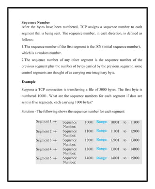
Sequence Number
After thebytes have been numbered, TCP assigns a sequence number to each
segment that is being sent. The sequence number, in each direction, is defined as
follows:
1.The sequence number of the first segment is the ISN (initial sequence number),
which is a random number.
2.The sequence number of any other segment is the sequence number of the
previous segment plus the number of bytes carried by the previous segment. some
control segments are thought of as carrying one imaginary byte.
Example
Suppose a TCP connection is transferring a file of 5000 bytes. The first byte is
numbered 10001. What are the sequence numbers for each segment if data are
sent in five segments, each carrying 1000 bytes?
Solution - The following shows the sequence number for each segment:
Segment 1 → Sequence
Number:
10001 Range: 10001 to 11000
Segment 2 → Sequence
Number:
11001 Range: 11001 to 12000
Segment 3 → Sequence
Number:
12001 Range: 12001 to 13000
Segment 4 → Sequence
Number:
13001 Range: 13001 to 14000
Segment 5 → Sequence
Number:
14001 Range: 14001 to 15000
54.
When a segmentcarries a combination of data and control information (piggy-
backing), it uses a sequence number. If a segment does not carry user data, it does
not logically define a sequence number. The field is there, but the value is not
valid. How- ever, some segments, when carrying only control information, need a
sequence number to allow an acknowledgment from the receiver. These segments
are used for connection establishment, termination, or abortion. Each of these
segments consume one sequence number as though it carries one byte, but there
are no actual data.
Acknowledgment Number
communication in TCP is full duplex; when a connection is established, both
parties can send and receive data at the same time. Each party numbers the
bytes, usually with a different starting byte number.
The sequence number in each direction shows the number of first byte carried by
the segment. Each party also uses an acknowledgment number to confirm the
bytes it has received. However, the acknowledgment number defines number of
next byte that party expects to receive. In addition, the acknowledgment number
is cumulative, which means that party takes the number of last byte that it has
received, safe and sound, adds 1 to it, and announces this sum as the
acknowledgment number.
55.
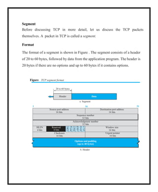
Options and padding
(upto 40 bytes)
20 to 60 bytes
Header Data
Segment
Before discussing TCP in more detail, let us discuss the TCP packets
themselves. A packet in TCP is called a segment.
Format
The format of a segment is shown in Figure . The segment consists of a header
of 20 to 60 bytes, followed by data from the application program. The header is
20 bytes if there are no options and up to 60 bytes if it contains options.
Figure TCP segment format
a. Segment
1 16 31
Source port address
16 bits
Destination port address
16 bits
Sequence number
32 bits
Acknowledgment number
32 bits
HLEN
4 bits
Reserved
6 bits
U
R
G
A
C
K
P
S
H
R
S
T
S
Y
N
F
I
N
Window size
16 bits
Checksum
16 bits
Urgent pointer
16 bits
b. Header
56.
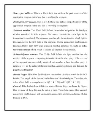
Source port address.This is a 16-bit field that defines the port number of the
application program in the host that is sending the segment.
Destination port address. This is a 16-bit field that defines the port number of the
application program in the host that is receiving the segment.
Sequence number. This 32-bit field defines the number assigned to the first byte
of data contained in this segment. To ensure connectivity, each byte to be
transmitted is numbered. The sequence number tells the destination which byte in
this sequence is the first byte in the segment. During connection establishment
(discussed later) each party uses a random number generator to create an initial
sequence number (ISN), which is usually different in each direction.
Acknowledgment number. This 32-bit field defines the byte number that the
receiver of the segment is expecting to receive from the other party. If the receiver
of the segment has successfully received byte number x from the other party, it
returns x 1 as the acknowledgment number. Acknowledgment and data can be
piggybacked together.
Header length. This 4-bit field indicates the number of 4-byte words in the TCP
header. The length of the header can be between 20 and 60 bytes. Therefore, the
value of this field is always between 5 (5 4 20) and 15 (15 4 60).
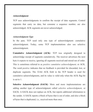
Control. This field defines 6 different control bits or flags, as shown in Figure.
One or more of these bits can be set at a time. These bits enable flow control,
connection establishment and termination, connection abortion, and mode of data
transfer in TCP.
57.
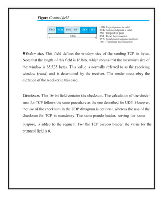
Figure Control field
URG:Urgent pointer is valid
ACK: Acknowledgment is valid
PSH : Request for push
RST : Reset the connection
SYN: Synchronize sequence numbers
FIN : Terminate the connection
Window size. This field defines the window size of the sending TCP in bytes.
Note that the length of this field is 16 bits, which means that the maximum size of
the window is 65,535 bytes. This value is normally referred to as the receiving
window (rwnd) and is determined by the receiver. The sender must obey the
dictation of the receiver in this case.
Checksum. This 16-bit field contains the checksum. The calculation of the check-
sum for TCP follows the same procedure as the one described for UDP. However,
the use of the checksum in the UDP datagram is optional, whereas the use of the
checksum for TCP is mandatory. The same pseudo header, serving the same
purpose, is added to the segment. For the TCP pseudo header, the value for the
protocol field is 6.
URG ACK PSH RST SYN FIN
6 bits
58.
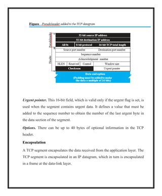
Urgent pointer. This16-bit field, which is valid only if the urgent flag is set, is
used when the segment contains urgent data. It defines a value that must be
added to the sequence number to obtain the number of the last urgent byte in
the data section of the segment.
Options. There can be up to 40 bytes of optional information in the TCP
header.
Encapsulation
A TCP segment encapsulates the data received from the application layer. The
TCP segment is encapsulated in an IP datagram, which in turn is encapsulated
in a frame at the data-link layer.
59.
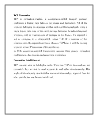
TCP Connection
TCP isconnection-oriented. a connection-oriented transport protocol
establishes a logical path between the source and destination. All of the
segments belonging to a message are then sent over this logical path. Using a
single logical path- way for the entire message facilitates the acknowledgment
process as well as retransmission of damaged or lost frames. If a segment is
lost or corrupted, it is retransmitted. Unlike TCP, IP is unaware of this
retransmission. If a segment arrives out of order, TCP holds it until the missing
segments arrive; IP is unaware of this reordering.
In TCP, connection-oriented transmission requires three phases: connection
establishment, data transfer, and connection termination.
Connection Establishment
TCP transmits data in full-duplex mode. When two TCPs in two machines are
connected, they are able to send segments to each other simultaneously. This
implies that each party must initialize communication and get approval from the
other party before any data are transferred.
60.
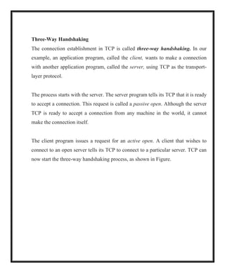
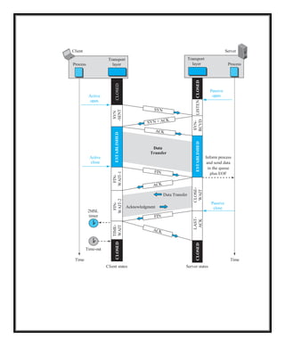
Three-Way Handshaking
The connectionestablishment in TCP is called three-way handshaking. In our
example, an application program, called the client, wants to make a connection
with another application program, called the server, using TCP as the transport-
layer protocol.
The process starts with the server. The server program tells its TCP that it is ready
to accept a connection. This request is called a passive open. Although the server
TCP is ready to accept a connection from any machine in the world, it cannot
make the connection itself.
The client program issues a request for an active open. A client that wishes to
connect to an open server tells its TCP to connect to a particular server. TCP can
now start the three-way handshaking process, as shown in Figure.
61.
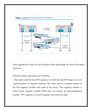
Each segment hasvalues for all its header fields and perhaps for some of its option
fields too.
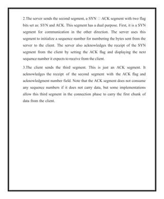
The three steps in this phase are as follows.
1.The client sends the first SYN segment, in which only the SYN flag is set is for
synchronization of sequence numbers. The client chooses a random number as
the first sequence number and sends to the server. This sequence number is
called initial sequence number (ISN) does not contain an acknowledgment
number. SYN segment is a control segment and carries no data.
62.
2.The server sendsthe second segment, a SYN ACK segment with two flag
bits set as: SYN and ACK. This segment has a dual purpose. First, it is a SYN
segment for communication in the other direction. The server uses this
segment to initialize a sequence number for numbering the bytes sent from the
server to the client. The server also acknowledges the receipt of the SYN
segment from the client by setting the ACK flag and displaying the next
sequence number it expects to receive from the client.
3.The client sends the third segment. This is just an ACK segment. It
acknowledges the receipt of the second segment with the ACK flag and
acknowledgment number field. Note that the ACK segment does not consume
any sequence numbers if it does not carry data, but some implementations
allow this third segment in the connection phase to carry the first chunk of
data from the client.
63.
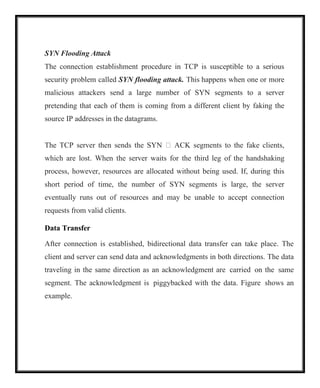
SYN Flooding Attack
Theconnection establishment procedure in TCP is susceptible to a serious
security problem called SYN flooding attack. This happens when one or more
malicious attackers send a large number of SYN segments to a server
pretending that each of them is coming from a different client by faking the
source IP addresses in the datagrams.
The TCP server then sends the SYN ACK segments to the fake clients,
which are lost. When the server waits for the third leg of the handshaking
process, however, resources are allocated without being used. If, during this
short period of time, the number of SYN segments is large, the server
eventually runs out of resources and may be unable to accept connection
requests from valid clients.
Data Transfer
After connection is established, bidirectional data transfer can take place. The
client and server can send data and acknowledgments in both directions. The data
traveling in the same direction as an acknowledgment are carried on the same
segment. The acknowledgment is piggybacked with the data. Figure shows an
example.
64.
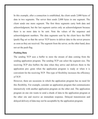
In this example,after a connection is established, the client sends 2,000 bytes of
data in two segments. The server then sends 2,000 bytes in one segment. The
client sends one more segment. The first three segments carry both data and
acknowledgment, but the last segment carries only an acknowledgment because
there is no more data to be sent. Note the values of the sequence and
acknowledgment numbers. The data segments sent by the client have the PSH
(push) flag set so that the server TCP knows to deliver data to the server process
as soon as they are received. The segment from the server, on the other hand, does
not set the push flag.
Pushing Data
The sending TCP uses a buffer to store the stream of data coming from the
sending application program. The sending TCP can select the segment size. The
receiving TCP also buffers the data when they arrive and delivers them to the
application pro- gram when the application program is ready or when it is
convenient for the receiving TCP. This type of flexibility increases the efficiency
of TCP.
However, there are occasions in which the application program has no need for
this flexibility. For example, consider an application program that communicates
interactively with another application program on the other end. The application
program on one site wants to send a chunk of data to the application program at
the other site and receive an immediate response. Delayed transmission and
delayed delivery of data may not be acceptable by the application program.
65.
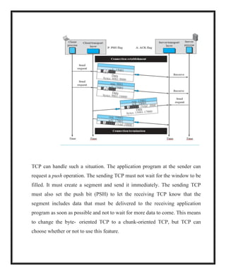
TCP can handlesuch a situation. The application program at the sender can
request a push operation. The sending TCP must not wait for the window to be
filled. It must create a segment and send it immediately. The sending TCP
must also set the push bit (PSH) to let the receiving TCP know that the
segment includes data that must be delivered to the receiving application
program as soon as possible and not to wait for more data to come. This means
to change the byte- oriented TCP to a chunk-oriented TCP, but TCP can
choose whether or not to use this feature.
66.
Connection Termination
Either ofthe two parties involved in exchanging data (client or server) can close
the connection, although it is usually initiated by the client. Most implementations
today allow two options for connection termination: three-way handshaking and
four-way handshaking with a half-close option.
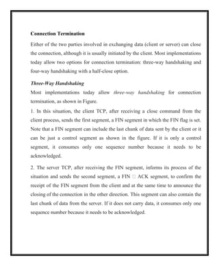
Three-Way Handshaking
Most implementations today allow three-way handshaking for connection
termination, as shown in Figure.
1. In this situation, the client TCP, after receiving a close command from the
client process, sends the first segment, a FIN segment in which the FIN flag is set.
Note that a FIN segment can include the last chunk of data sent by the client or it
can be just a control segment as shown in the figure. If it is only a control
segment, it consumes only one sequence number because it needs to be
acknowledged.
2. The server TCP, after receiving the FIN segment, informs its process of the
situation and sends the second segment, a FIN ACK segment, to confirm the
receipt of the FIN segment from the client and at the same time to announce the
closing of the connection in the other direction. This segment can also contain the
last chunk of data from the server. If it does not carry data, it consumes only one
sequence number because it needs to be acknowledged.
67.
The client TCPsends the last segment, an ACK segment, to confirm the receipt of
the FIN segment from the TCP server. This segment contains the
acknowledgment number, which is one plus the sequence number received in the
FIN segment from the server. This segment cannot carry data and consumes no
sequence numbers.
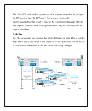
Half-Close
In TCP, one end can stop sending data while still receiving data. This is called a
half- close. Either the server or the client can issue a half-close request. It can
occur when the server needs all the data before processing can begin.
68.
the client sendsdata to the server to be sorted, the server needs to receive all
the data before sorting can start. This means the client, after sending all data,
can close the connection in the client-to-server direction. However, the server-
to-client direction must remain open to return the sorted data. The server, after
receiving the data, still needs time for sorting; its outbound direction must
remain open. Figure shows an example of a half-close.
The data transfer from the client to the server stops. The client half-closes the
connection by sending a FIN segment. The server accepts the half-close by
sending the ACK segment. The server, however, can still send data. When the
server has sent all of the processed data, it sends a FIN segment, which is
acknowledged by an ACK from the client.
After half-closing the connection, data can travel from the server to the client
and acknowledgments can travel from the client to the server. The client
cannot send any more data to the server.
Windows in TCP
TCPuses two windows for each direction of data transfer, which means four
windows for a bidirectional communication. communication is only
unidirectional; the bidirectional communication can be inferred using two
unidirectional communications with piggybacking.
71.
Sf Sn
200
bytes
(Usable window)
Bytesthat cannot be
moves to the right
Send window size (advertised by the receiver)
300
260 261
201 301
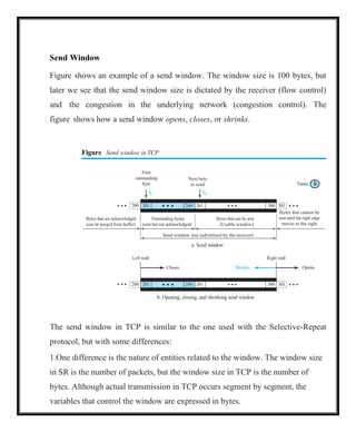
Send Window
Figure shows an example of a send window. The window size is 100 bytes, but
later we see that the send window size is dictated by the receiver (flow control)
and the congestion in the underlying network (congestion control). The
figure shows how a send window opens, closes, or shrinks.
Figure Send window in TCP
First
outstanding
byte
Next byte
to send
a. Send window
Timer
Left wall Right wall
Opens
b. Opening, closing, and shrinking send window
The send window in TCP is similar to the one used with the Selective-Repeat
protocol, but with some differences:
1.One difference is the nature of entities related to the window. The window size
in SR is the number of packets, but the window size in TCP is the number of
bytes. Although actual transmission in TCP occurs segment by segment, the
variables that control the window are expressed in bytes.
Closes Shrinks
200 201 260 261 300 301
72.
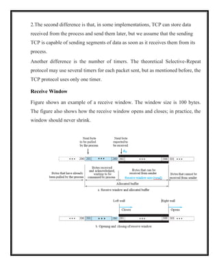
2.The second differenceis that, in some implementations, TCP can store data
received from the process and send them later, but we assume that the sending
TCP is capable of sending segments of data as soon as it receives them from its
process.
Another difference is the number of timers. The theoretical Selective-Repeat
protocol may use several timers for each packet sent, but as mentioned before, the
TCP protocol uses only one timer.
Receive Window
Figure shows an example of a receive window. The window size is 100 bytes.
The figure also shows how the receive window opens and closes; in practice, the
window should never shrink.
73.
There are twodifferences between the receive window in TCP and the one we
used for SR.
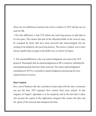
1.The first difference is that TCP allows the receiving process to pull data at
its own pace. This means that part of the allocated buffer at the receiver may
be occupied by bytes that have been received and acknowledged, but are
waiting to be pulled by the receiving process. The receive window size is then
always smaller than or equal to the buffer size, as shown in Figure .
2. The second difference is the way acknowledgments are used in the TCP
protocol. Remember that an acknowledgement in SR is selective, defining the
uncorrupted packets that have been received. The major acknowledgment
mechanism in TCP is a cumulative acknowledgment announcing the next
expected byte to receive.
Flow Control
flow control balances the rate a producer creates data with the rate a consumer
can use the data. TCP separates flow control from error control. In this
elegance of Nagle’s algorithm is in its simplicity and in the fact that it takes
into account the speed of the application program that creates the data and
the speed of the network that transports the data.
74.
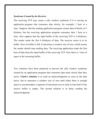
Syndrome Created bythe Receiver
The receiving TCP may create a silly window syndrome if it is serving an
application program that consumes data slowly, for example, 1 byte at a
time. Suppose that the sending application program creates data in blocks of 1
kilobyte, but the receiving application program consumes data 1 byte at a
time. Also suppose that the input buffer of the receiving TCP is 4 kilobytes.
The sender sends the first 4 kilobytes of data. The receiver stores it in its
buffer. Now its buffer is full. It advertises a window size of zero, which means
the sender should stop sending data. The receiving application reads the first
byte of data from the input buffer of the receiving TCP. Now there is 1 byte of
space in the incoming buffer.
Two solutions have been proposed to prevent the silly window syndrome
created by an application program that consumes data more slowly than they
arrive. Clark’s solution is to send an acknowledgment as soon as the data
arrive, but to announce a window size of zero until either there is enough
space to accommodate a segment of maximum size or until at least half of the
receive buffer is empty. The second solution is to delay sending the
acknowledgment.
75.
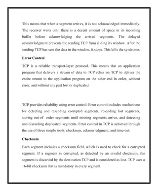
This means thatwhen a segment arrives, it is not acknowledged immediately.
The receiver waits until there is a decent amount of space in its incoming
buffer before acknowledging the arrived segments. The delayed
acknowledgment prevents the sending TCP from sliding its window. After the
sending TCP has sent the data in the window, it stops. This kills the syndrome.
Error Control
TCP is a reliable transport-layer protocol. This means that an application
program that delivers a stream of data to TCP relies on TCP to deliver the
entire stream to the application program on the other end in order, without
error, and without any part lost or duplicated.
TCP provides reliability using error control. Error control includes mechanisms
for detecting and resending corrupted segments, resending lost segments,
storing out-of- order segments until missing segments arrive, and detecting
and discarding duplicated segments. Error control in TCP is achieved through
the use of three simple tools: checksum, acknowledgment, and time-out.
Checksum
Each segment includes a checksum field, which is used to check for a corrupted
segment. If a segment is corrupted, as detected by an invalid checksum, the
segment is discarded by the destination TCP and is considered as lost. TCP uses a
16-bit checksum that is mandatory in every segment.
76.
Acknowledgment
TCP uses acknowledgmentsto confirm the receipt of data segments. Control
segments that carry no data, but consume a sequence number, are also
acknowledged. ACK segments are never acknowledged.
Acknowledgment Type
In the past, TCP used only one type of acknowledgment: cumulative
acknowledgment. Today, some TCP implementations also use selective
acknowledgment.
Cumulative Acknowledgment (ACK) TCP was originally designed to
acknowledge receipt of segments cumulatively. The receiver advertises the next
byte it expects to receive, ignoring all segments received and stored out of order.
This is sometimes referred to as positive cumulative acknowledgment, or ACK.
The word positive indicates that no feedback is provided for discarded, lost, or
duplicate segments. The 32-bit ACK field in the TCP header is used for
cumulative acknowledgments, and its value is valid only when the ACK flag bit
is set to 1.
Selective Acknowledgment (SACK) More and more implementations are
adding another type of acknowledgment called selective acknowledgment, or
SACK. A SACK does not replace an ACK, but reports additional information to
the sender. A SACK reports a block of bytes that is out of order, and also a block
of bytes that is duplicated, i.e., received more than once.
77.
Generating Acknowledgments
The orderof a rule does not necessarily define its importance.
1.When end A sends a data segment to end B, it must include (piggyback) an
acknowledgment that gives the next sequence number it expects to receive. This
rule decreases the number of segments needed and therefore reduces traffic.
When the receiver has no data to send and it receives an in-order segment and the
previous segment has already been acknowledged, the receiver delays sending
an ACK segment until another segment 2arrives or until a period of time
(normally 500 ms) has passed.
2.When a segment arrives with a sequence number that is expected by the
receiver, and the previous in-order segment has not been acknowledged, the
receiver immediately sends an ACK segment. In other words, there should not
be more than two in-order unacknowledged segments at any time. This
prevents the unnecessary retransmission of segments that may create
congestion in the network.
3.When a segment arrives with an out-of-order sequence number that is higher
than expected, the receiver immediately sends an ACK segment announcing
the sequence number of the next expected segment. This leads to the fast
retransmission of missing segments.
78.
4.When a missingsegment arrives, the receiver sends an ACK segment to
announce the next sequence number expected. This informs the receiver that
segments reported missing have been received.
5.If a duplicate segment arrives, the receiver discards the segment, but
immediately sends an acknowledgment indicating the next in-order segment
expected. This solves some problems when an ACK segment itself is lost.
Retransmission
The heart of the error control mechanism is the retransmission of segments.
When a segment is sent, it is stored in a queue until it is acknowledged. When
the retransmission timer expires or when the sender receives three duplicate
ACKs for the first segment in the queue, that segment is retransmitted.
Retransmission after RTO
The sending TCP maintains one retransmission time-out (RTO) for each
connection. When the timer matures, i.e. times out, TCP resends the segment
in the front of the queue (the segment with the smallest sequence number)
and restarts the timer.
when Sf Sn the value of RTO is dynamic in TCP and is updated based on
the round-trip time (RTT) of segments. RTT is the time needed for a
segment to reach a destination and for an acknowledgment to be received.
Retransmission after Three Duplicate ACK Segments
79.
The previous ruleabout retransmission of a segment is sufficient if the value of
RTO is not large. To expedite service throughout the Internet by allowing
senders to retransmit without waiting for a time out, most implementations
today follow the three duplicate ACKs rule and retransmit the missing
segment immediately. This feature is called fast retransmission. In this
version, if three duplicate acknowledgments arrive for a segment, the next
segment is retransmitted without waiting for the time-out.
Out-of-Order Segments
TCP implementations today do not discard out-of-order segments. They store
them temporarily and flag them as out-of-order segments until the missing
segments arrive.
Note, however, that out-of-order segments are never delivered to the process.
TCP guarantees that data are delivered to the process in order.
FSMs for Data Transfer in TCP
Data transfer in TCP is close to the Selective-Repeat protocol with a slight
similarity to GBN. Since TCP accepts out-of-order segments, TCP can be thought
of as behaving more like the SR protocol, but since the original acknowledgments
are cumulative, it looks like GBN. However, if the TCP implementation uses
SACKs, then TCP is closest to SR.
80.
Sender-Side FSM
The communicationis unidirectional and the segments are acknowledged using
ACK segments. ignore selective acknowledgments and congestion control for the
moment. Figure shows the simplified FSM for the sender site.
81.
FSM is rudimentary;it does not include issues such as silly window syndrome
(Nagle’s algorithm) or window shutdown. It defines a unidirectional
communication, ignoring all issues that affect bidirectional communication.
Receiver-Side FSM
The communication is unidirectional and the segments are acknowledged
using ACK segments. ignore the selective acknowledgment and congestion
control for the moment. Figure shows the simplified FSM for the receiver.
82.
TCP Congestion Control
TCPuses different policies to handle the congestion in the network.
Congestion Window
The size of the send window is controlled by the receiver using the value of rwnd,
which is advertised in each segment traveling in the opposite direction. The use
of this strategy guarantees that the receive window is never overflowed with the
received bytes (no end congestion). This, however, does not mean that the
intermediate buffers, buffers in the routers, do not become congested. In other
words, there is no congestion at the other end, but there may be congestion in the
middle. TCP needs to worry about congestion in the middle because many
segments lost may seriously affect the error control. More segment loss means
resending the same segments again, resulting in worsening the congestion, and
finally the collapse of the communication.
TCP is an end-to-end protocol that uses the service of IP. The congestion in the
router is in the IP territory and should be taken care of by IP.
TCP cannot ignore the congestion in the network; it cannot aggressively send
segments to the network. The result of such aggressiveness would hurt the TCP
itself, as we mentioned before. TCP cannot be very conservative, either, sending a
small number of segments in each time interval, because this means not utilizing
the available band- width of the network. TCP needs to define policies that
accelerate the data transmission when there is no congestion and decelerate the
transmission when congestion is detected.
83.
To control thenumber of segments to transmit, TCP uses another variable called
a congestion window, cwnd, whose size is controlled by the congestion situation
in the network (as we will explain shortly). The cwnd variable and the rwnd
variable together define the size of the send window in TCP. The first is related to
the congestion in the middle (network); the second is related to the congestion at
the end. The actual size of the window is the minimum of these two.
Actual window size 5 minimum (rwnd, cwnd)
84.
Congestion Detection
The TCPsender uses the occurrence of two events as signs of congestion in
the network: time-out and receiving three duplicate ACKs.
The first is the time-out. If a TCP sender does not receive an ACK for a
segment or a group of segments before the time-out occurs, it assumes that the
corresponding segment or segments are lost and the loss is due to congestion.
Another event is the receiving of three duplicate ACKs (four ACKs with the
same acknowledgment number). Recall that when a TCP receiver sends a
duplicate ACK, it is the sign that a segment has been delayed, but sending
three duplicate ACKs is the sign of a missing segment, which can be due to
congestion in the network. However, the congestion in the case of three
duplicate ACKs can be less severe than in the case of time-out. When a
receiver sends three duplicate ACKs, it means that one segment is missing, but
three segments have been received. The network is either slightly congested or
has recovered from the congestion.
A very interesting point in TCP congestion is that the TCP sender uses only
one feedback from the other end to detect congestion: ACKs. The lack of
regular, timely receipt of ACKs, which results in a time-out, is the sign of a
strong congestion; the receiving of three duplicate ACKs is the sign of a weak
congestion in the network.