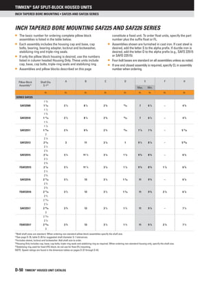
This document provides guidelines for shelf life and storage of grease-lubricated bearings, components, and assemblies from Timken. It states that shelf life represents the time prior to use and is separate from overall design life, and can be less depending on storage conditions. Timken's shelf life guidelines assume best storage practices are followed, including keeping products in original packaging, storing in a temperature and humidity controlled area away from contaminants and vibration, and not exceeding the stated shelf life. Adhering to these storage conditions helps maximize the time products can be kept before use.


![Timken®
SAF SPLIT-BLOCK HOUSED UNITS
D-34 TIMKEN®
HOUSED UNIT CATALOG
Engineering • GREASE LUBRICATIONS FOR BEARING/HOUSING ASSEMBLIES • GENERAL-PURPOSE INDUSTRIAL GREASE
Application Considerations
For higher-speed applications (operating at 75 percent of the
grease speed rating or more), a grease with a lighter base oil
viscosity (ISO 100-150) can be considered. Conversely, for lower-
speed applications, a grease with a heavier base oil viscosity
(ISO 320-460) can be considered. For lower-speed applications
operatingatcolderstart-uptemperatures(-18°C[0°F]),consider
a softer grease (NLGI grade 1) with an approved EP additive. The
lighter grade will allow more grease flow into the bearing contact
area and the EP additive will reduce wear during start-up. An ISO
460 base oil viscosity also can be considered.
When lower-speed applications operate at higher temperatures
(149° C [300° F]), consult a local Timken engineer.
Grease Fill
For normal industrial applications, fill the bearing void to 100
percent full and the housing void to 40 – 60 percent full. For
high-speed applications, fill the bearing void to 100 percent full
and the housing void to 30 – 40 percent full. The free volume of
the bearing can be estimated by first calculating the solid ring
volume of the bearing. Then, weigh the bearing and divide the
weight by the density of steel. This actual volume can then be
subtracted from the solid ring volume. The resultant value is an
estimate of the free volume of the bearing available for grease
fill. When the grease volume is determined for the application,
multiplying this value by the density of the grease will yield the
approximate weight of the grease fill. After weighing the grease
required, apply approximately 75 percent of the amount into the
cage androllerassembly. Theremainingamountofgreaseshould
then be applied to both inner and outer rings in equal amounts.
The preservatives applied to bearing components are compatible
with nearly all industrial greases and should not be wiped or
cleaned prior to packing the bearing. If in doubt, contact a local
Timken engineer.](https://image.slidesharecdn.com/timkenbearing-230202072509-81cd7a56/85/Timken-bearing-pdf-50-320.jpg)


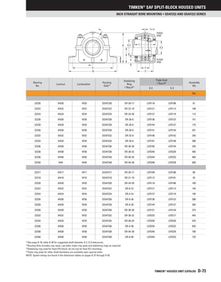


![Timken®
SAF SPLIT-BLOCK HOUSED UNITS
D-84 TIMKEN®
HOUSED UNIT CATALOG
SAF Spherical Roller Bearing INCH Accessories • Nomenclature
NOMENCLATURE
Timken provides accessories for your every need. To complement
our line of Timken®
spherical roller bearings, we offer bearing
sleeves and locking devices in a wide range of sizes. These
accessories are manufactured to the same quality standards as
our bearings, ensuring a secure fit to straight and stepped shafts.
Available in sizes up to 1000 mm (39.3701 in.), bearing sleeves are
available in two distinct designs: assembled adapter sleeves and
withdrawal sleeves.
ADAPTER SLEEVES
Timken adapter sleeves are used in conjunction with a nut and
locking device to mount a tapered bore bearing onto a straight
shaftusingapull-typefit.Smallersizeassemblies(20mm[0.78in.]-
200 mm [12 in.] shaft) commonly use simple nuts, whereas larger
assemblies (sizes 200 mm [12 in.]) may use HMV hydraulic
nuts to assist in mounting. Table D-24 outlines our part number
nomenclature, which is consistent with world standards for
adapter sleeves.
Table D-24. Inch Adapter sleeves (SNW, SNP) for
inch shaft sizes are supplied with
corresponding locknut and locking device
Assembly Sleeve Locknut Locking Device
SNW S N, AN W
SNP S N P
NOTE: SNW assembly consists of a sleeve, locknut and lockwasher.
NOTE: SNP assembly consists of a sleeve, locknut and lockplate.
NOTE: Metric accessories are available. Please reference the Timken Spherical
Roller Bearing Catalog (order no. 10446).
WITHDRAWAL SLEEVES
Withdrawal sleeves feature a push-type mounting arrangement
andalockingdevice(i.e.,locknutorlockplate)tosecureabearing
to a shaft. This design is not as widely used as the adapter
sleeve assembly, and it does require the use of a specially
designed dismounting nut. Timken’s part number nomenclature
for withdrawal sleeves also conforms to industry-accepted
standards. Nuts are not supplied with the withdrawal sleeve and
must be ordered separately. The dismounting of large assemblies
can be eased by using a hydraulic nut (HMV).
Table D-25. Inch withdrawal sleeve for
Inch shaft sizes
Sleeve Locknut Lockwasher/Plate Dismounting Nut
SK N, AN W, P AN, ARN, RN, N](https://image.slidesharecdn.com/timkenbearing-230202072509-81cd7a56/85/Timken-bearing-pdf-100-320.jpg)