Downloaded 166 times
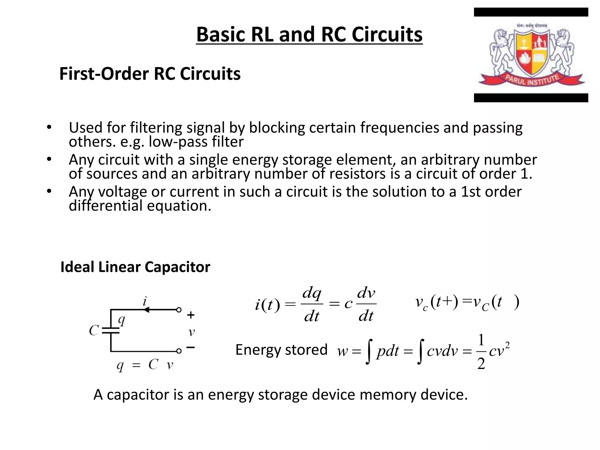
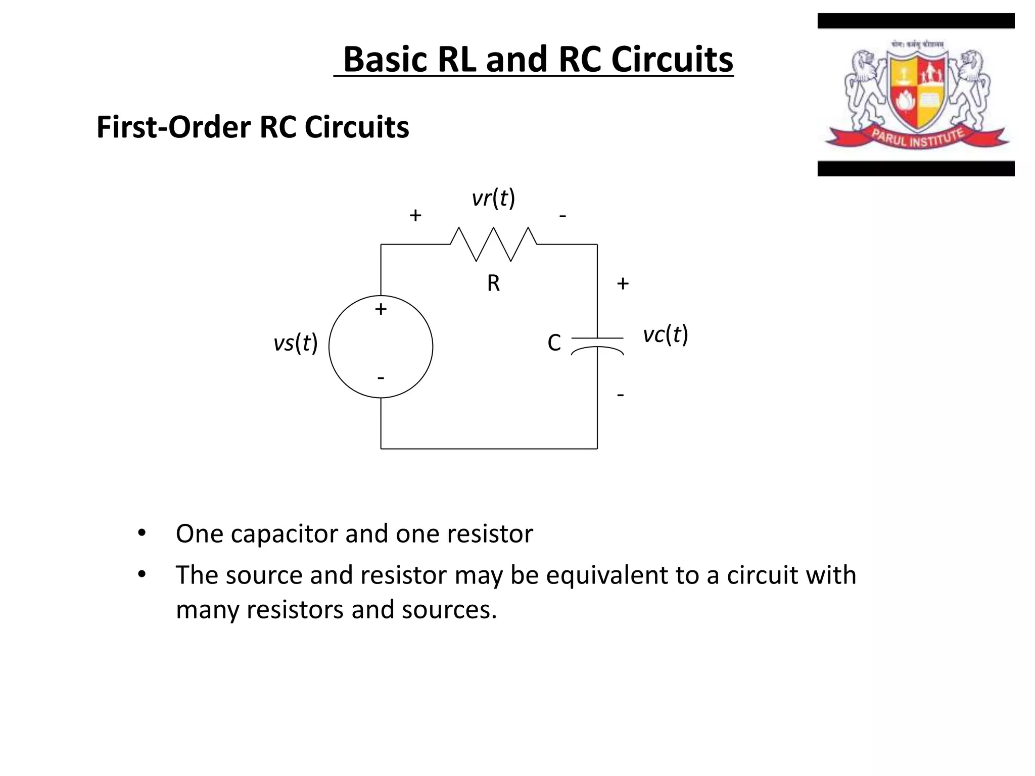
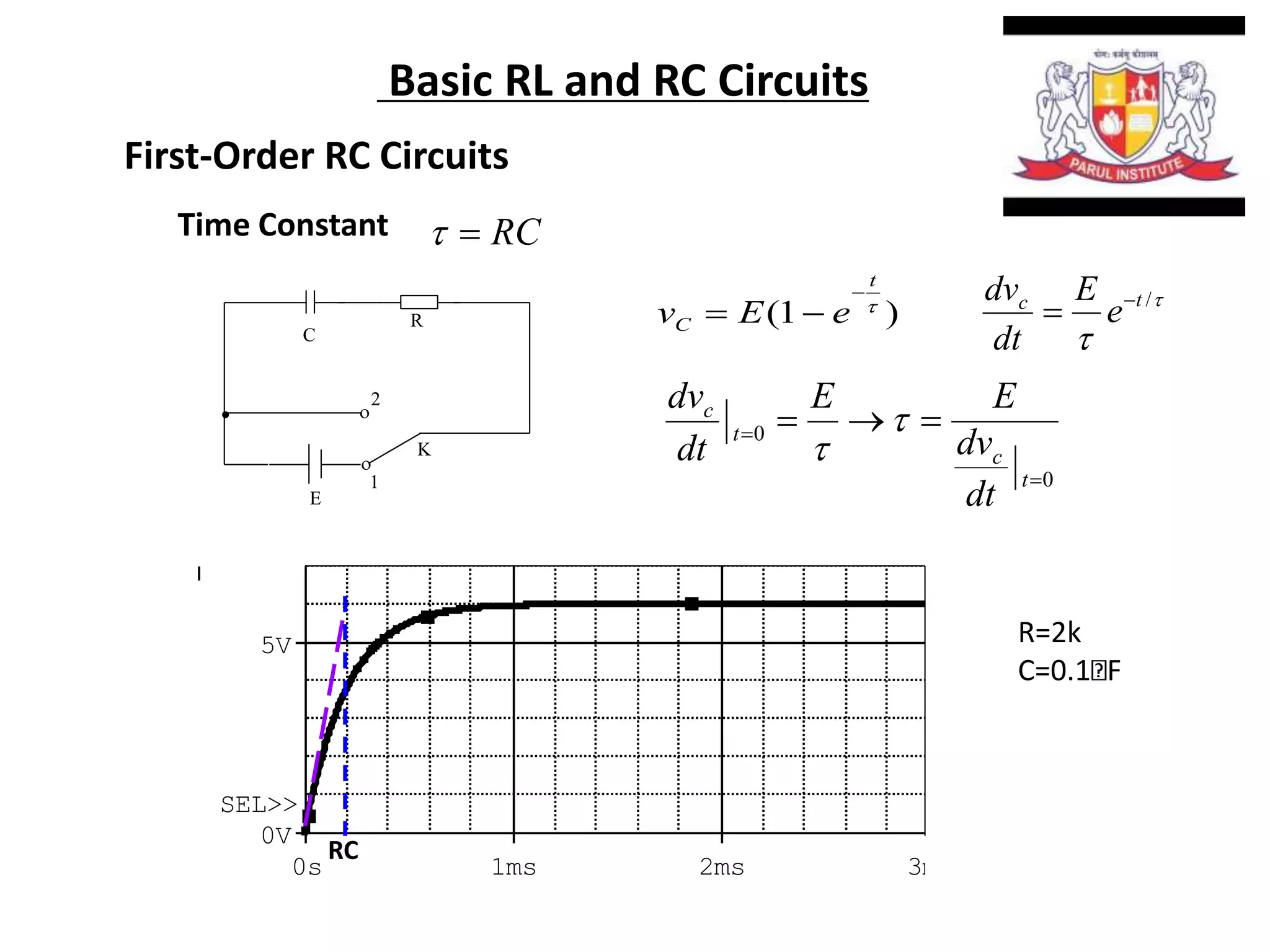
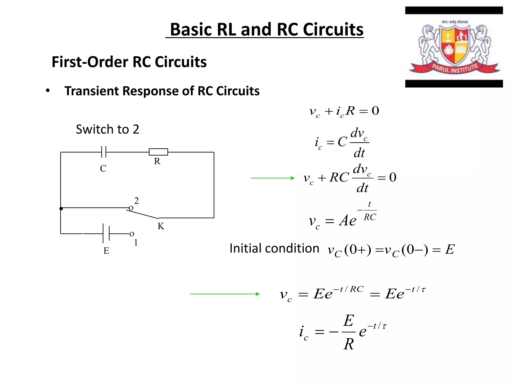
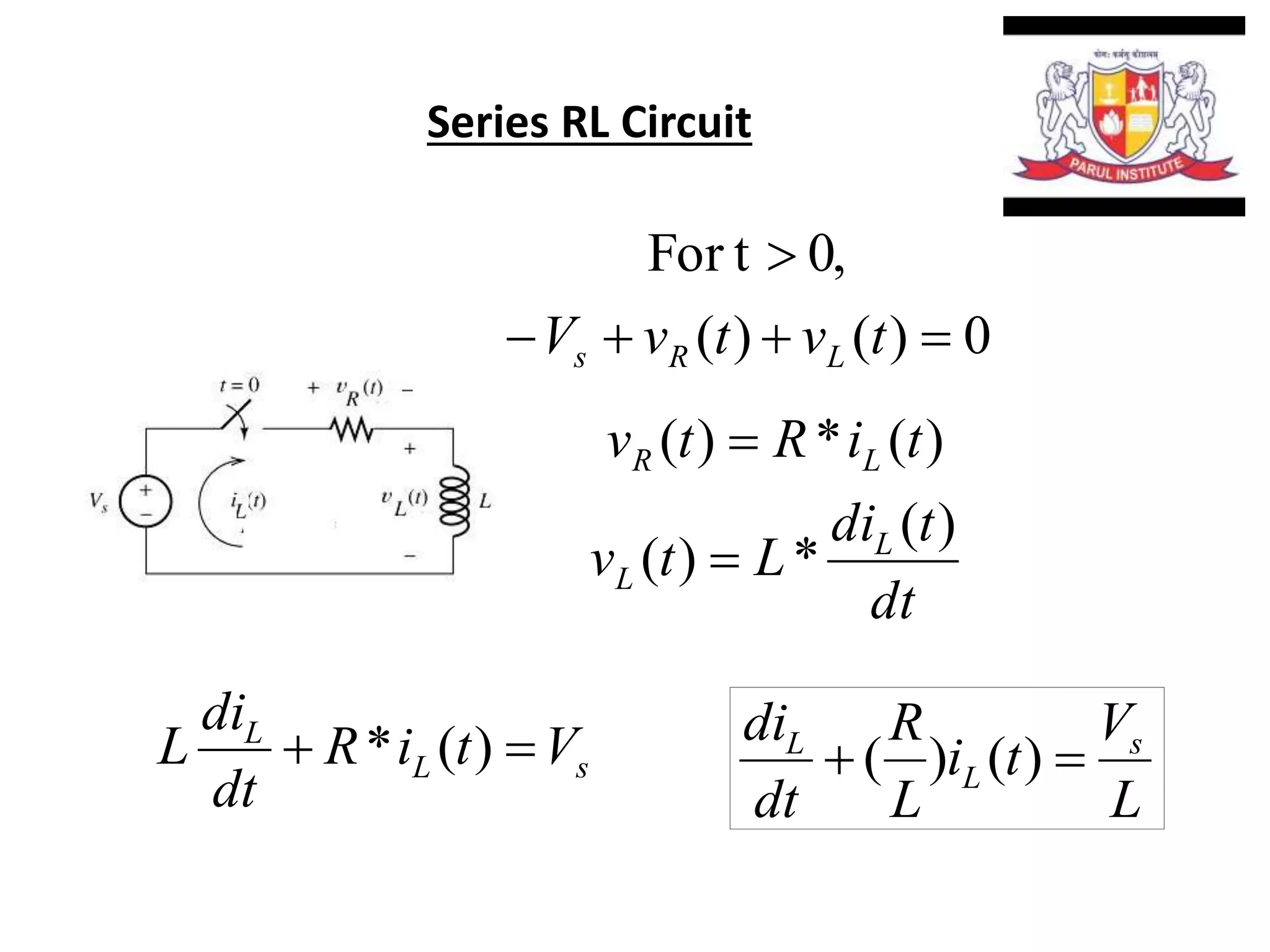
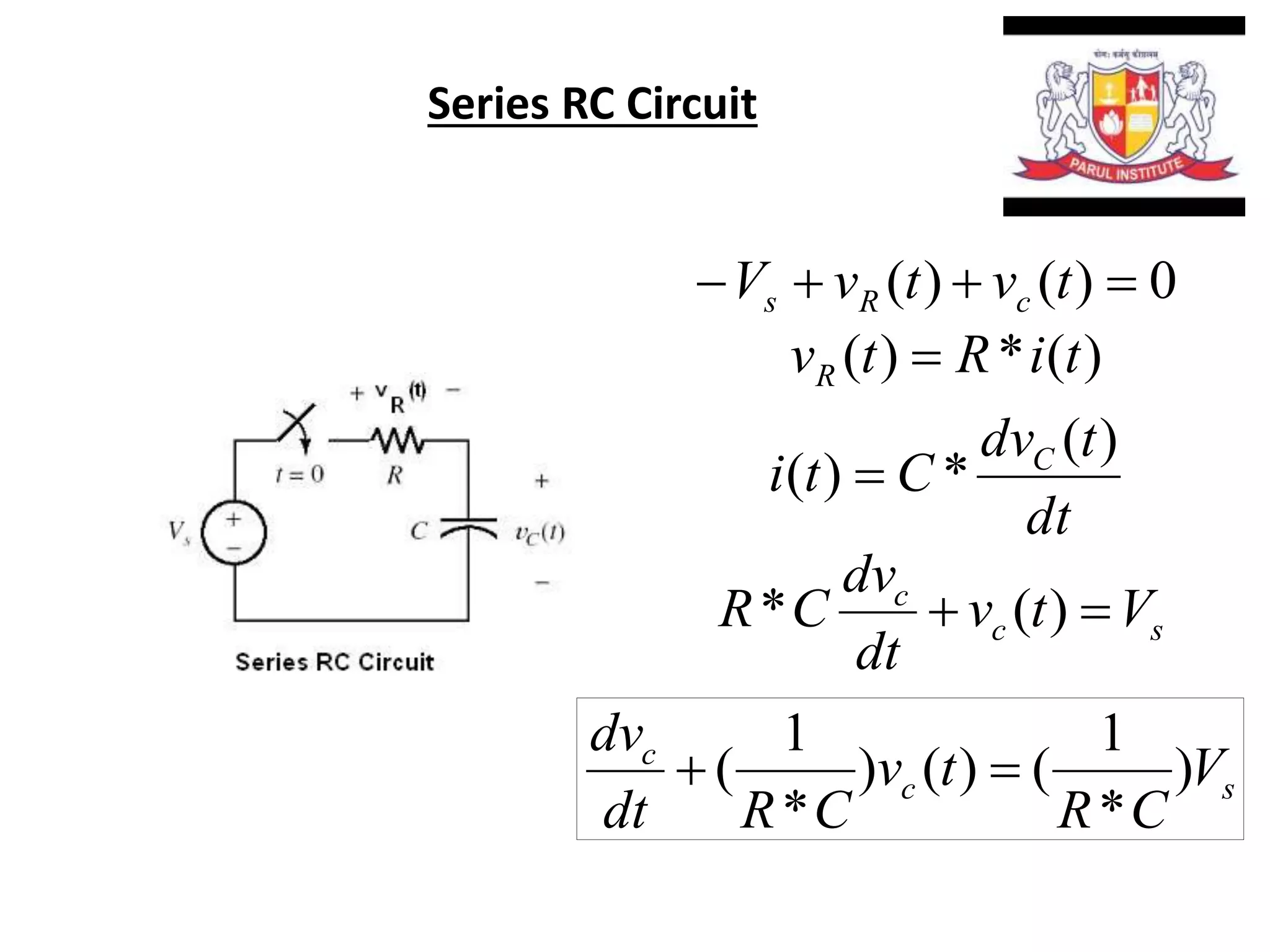
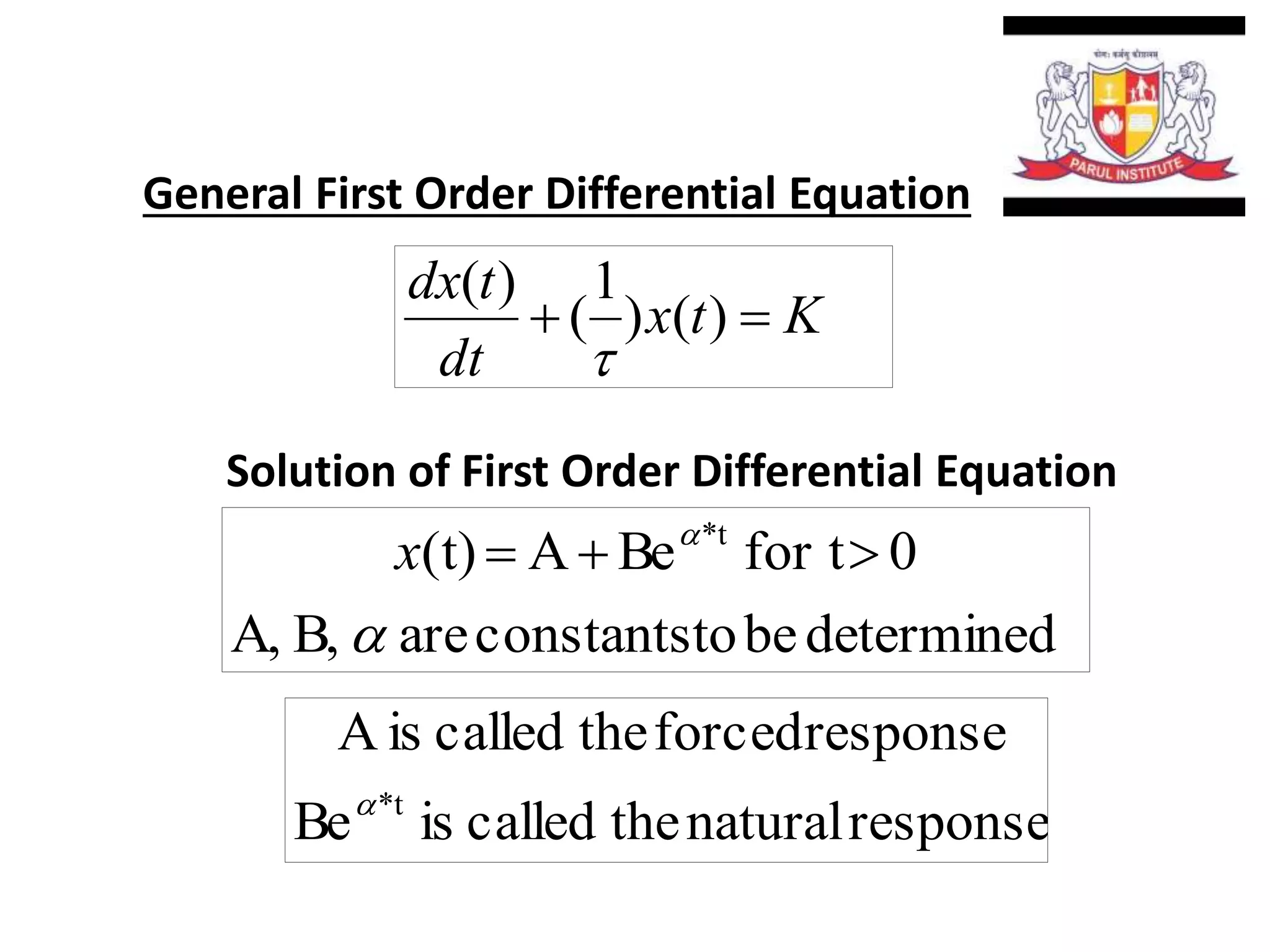
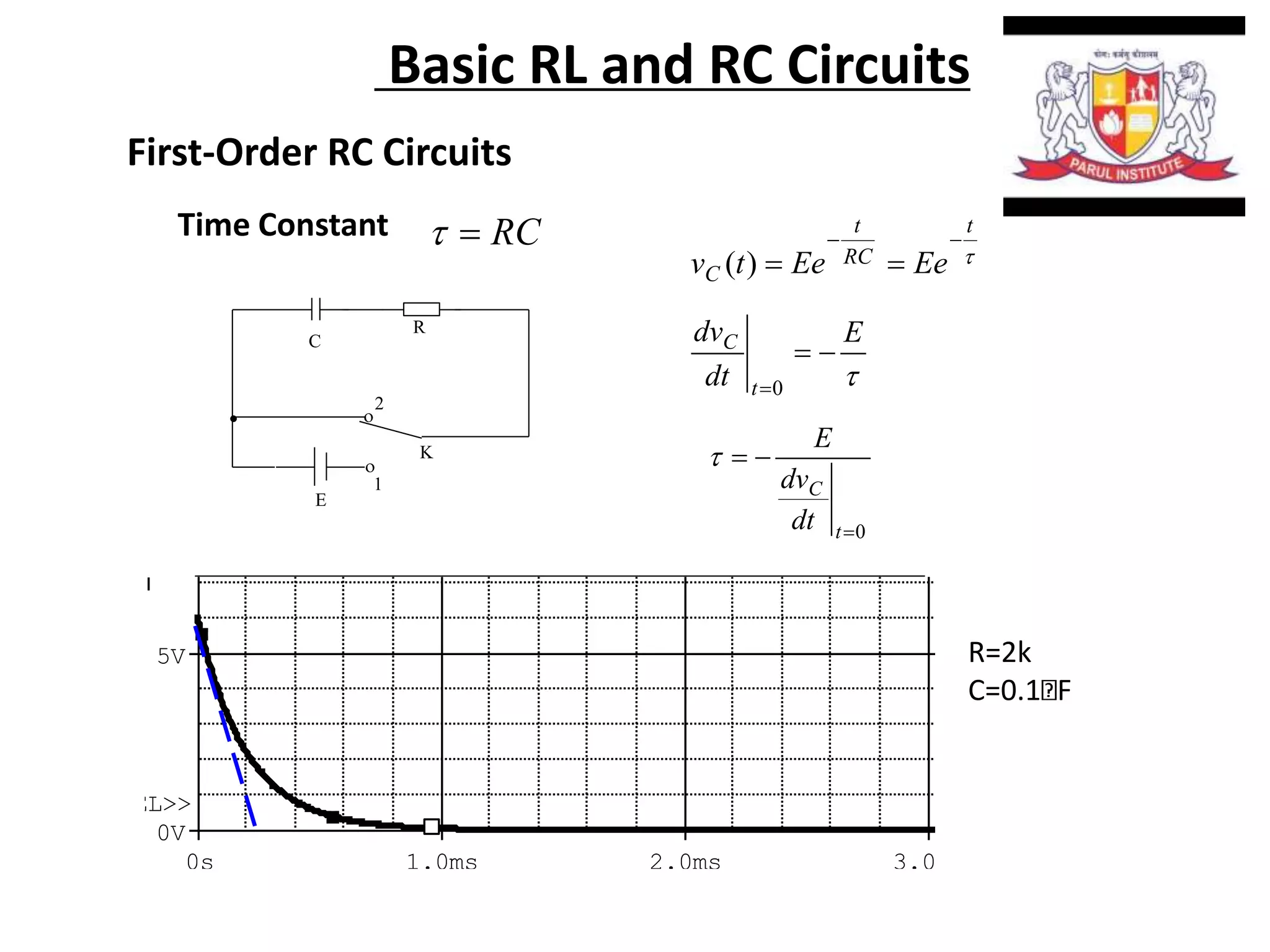
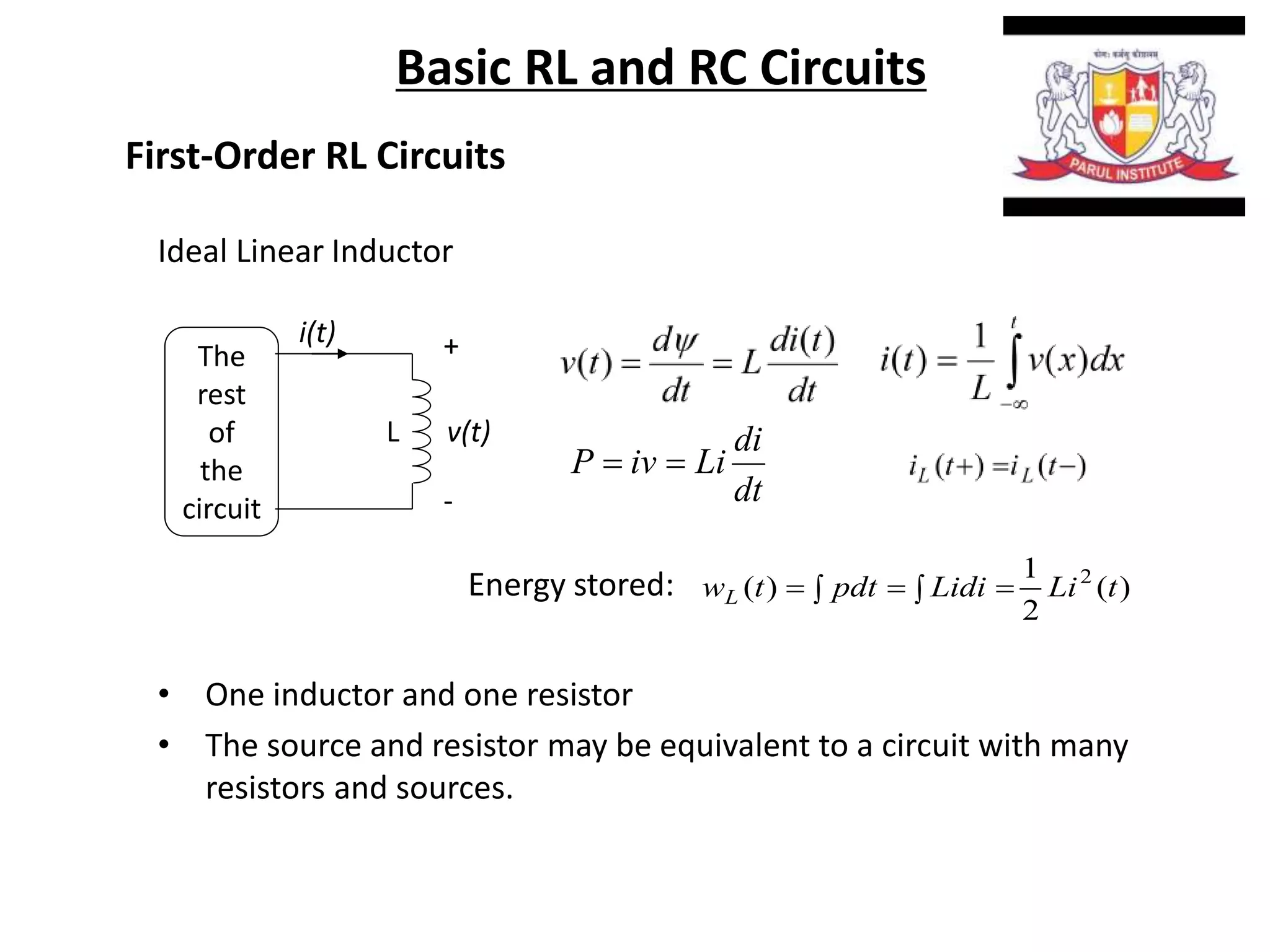
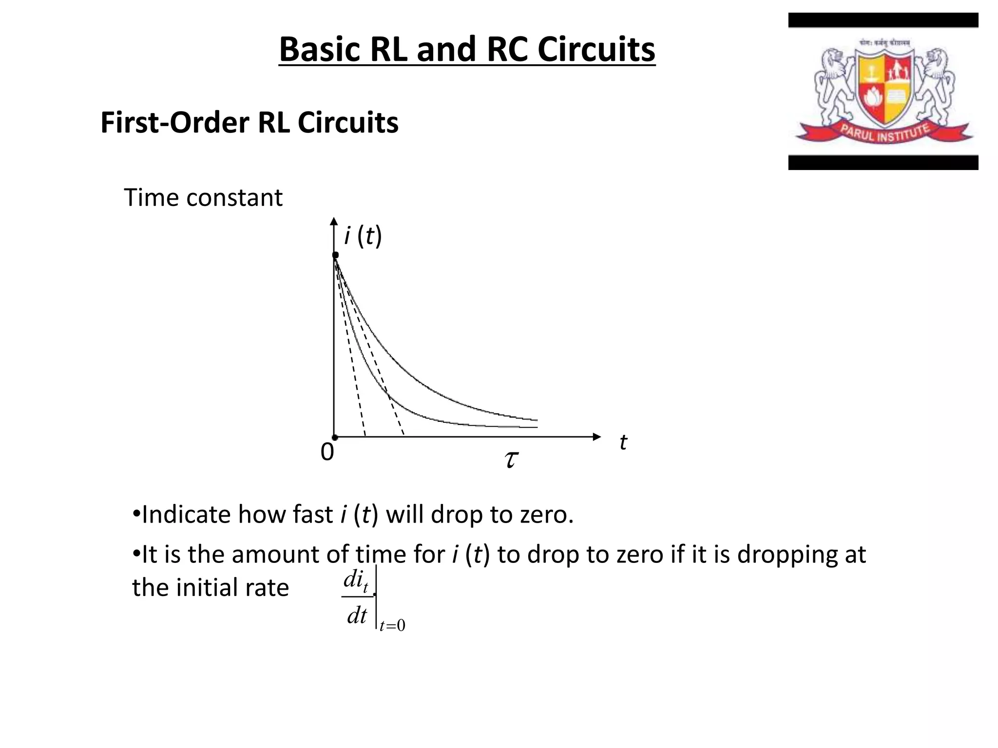

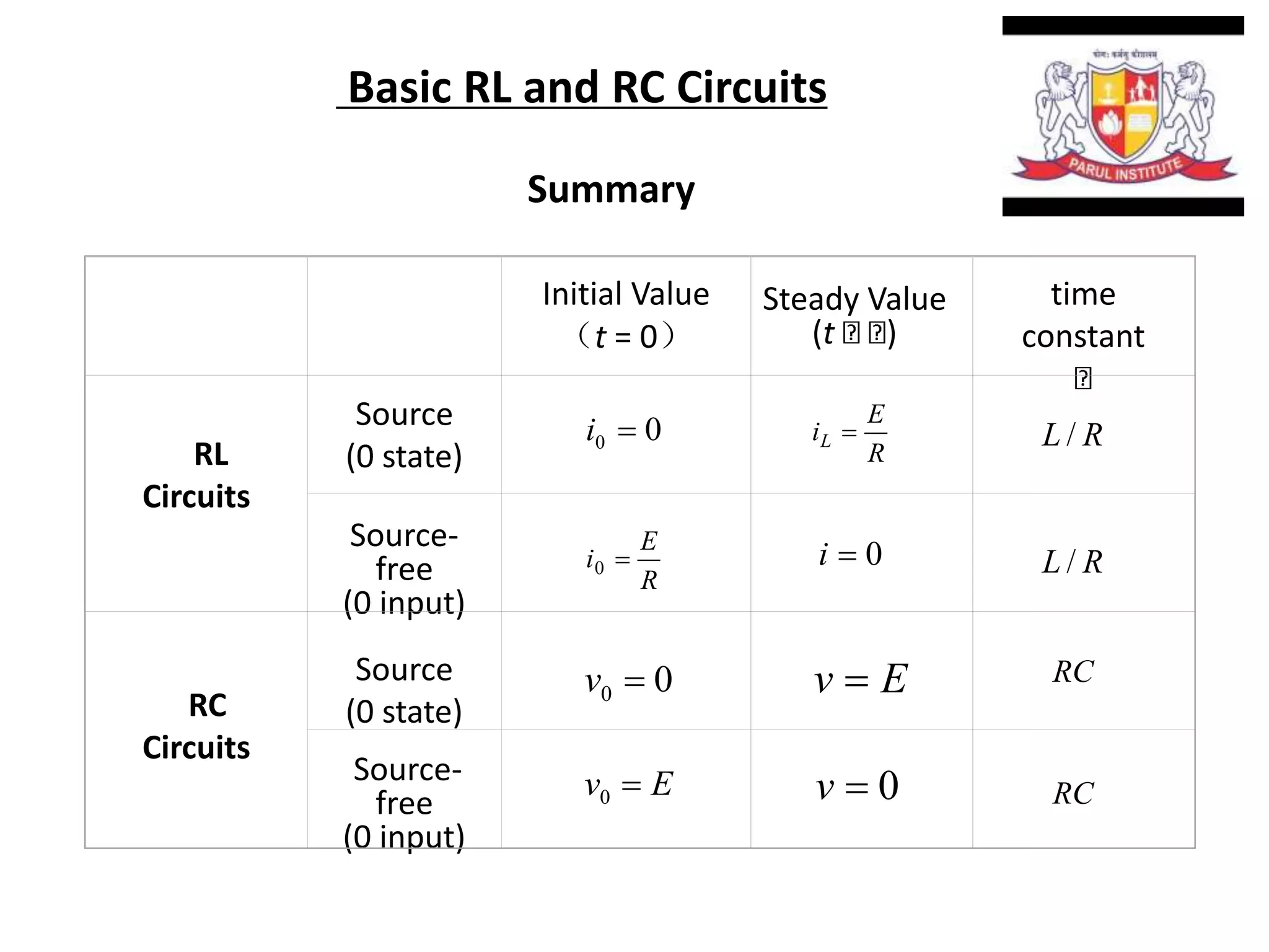
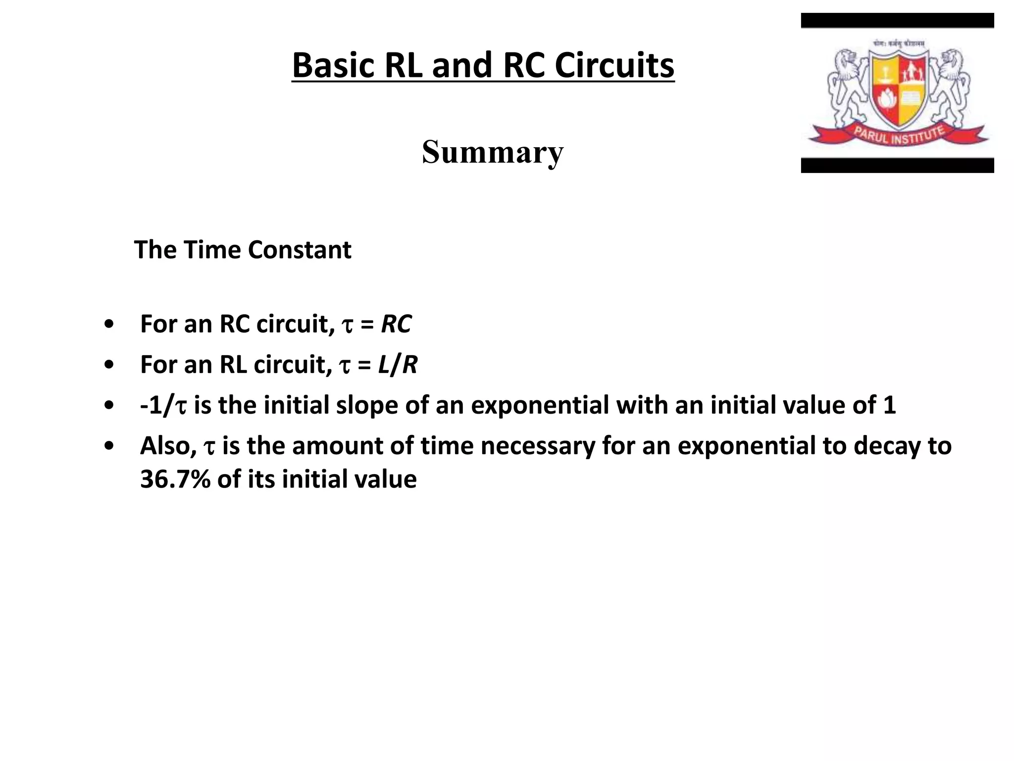


The document summarizes time domain responses in RC and RL circuits. It describes that transients are the time-varying currents and voltages resulting from sudden changes in sources. RC circuits with a single energy storage element are first-order circuits that can be used for filtering. The time constant for an RC circuit is RC and for an RL circuit is L/R. It represents the time required for an exponential to decay to 36.7% of its initial value. The document also discusses determining the initial conditions for transient analysis based on inductor current and capacitor voltage remaining constant during circuit changes.


![RF Module Design - [Chapter 6] Power Amplifier](https://cdn.slidesharecdn.com/ss_thumbnails/rfch6-150613070347-lva1-app6891-thumbnail.jpg?width=640&height=640&fit=bounds)