Download to read offline
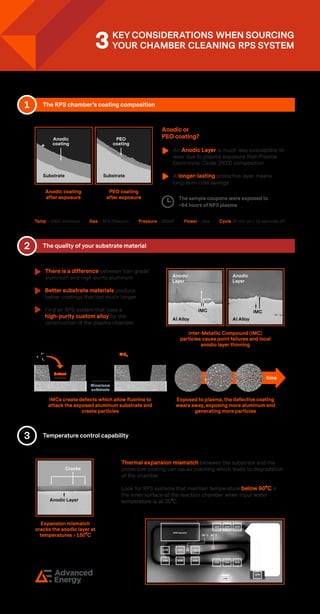
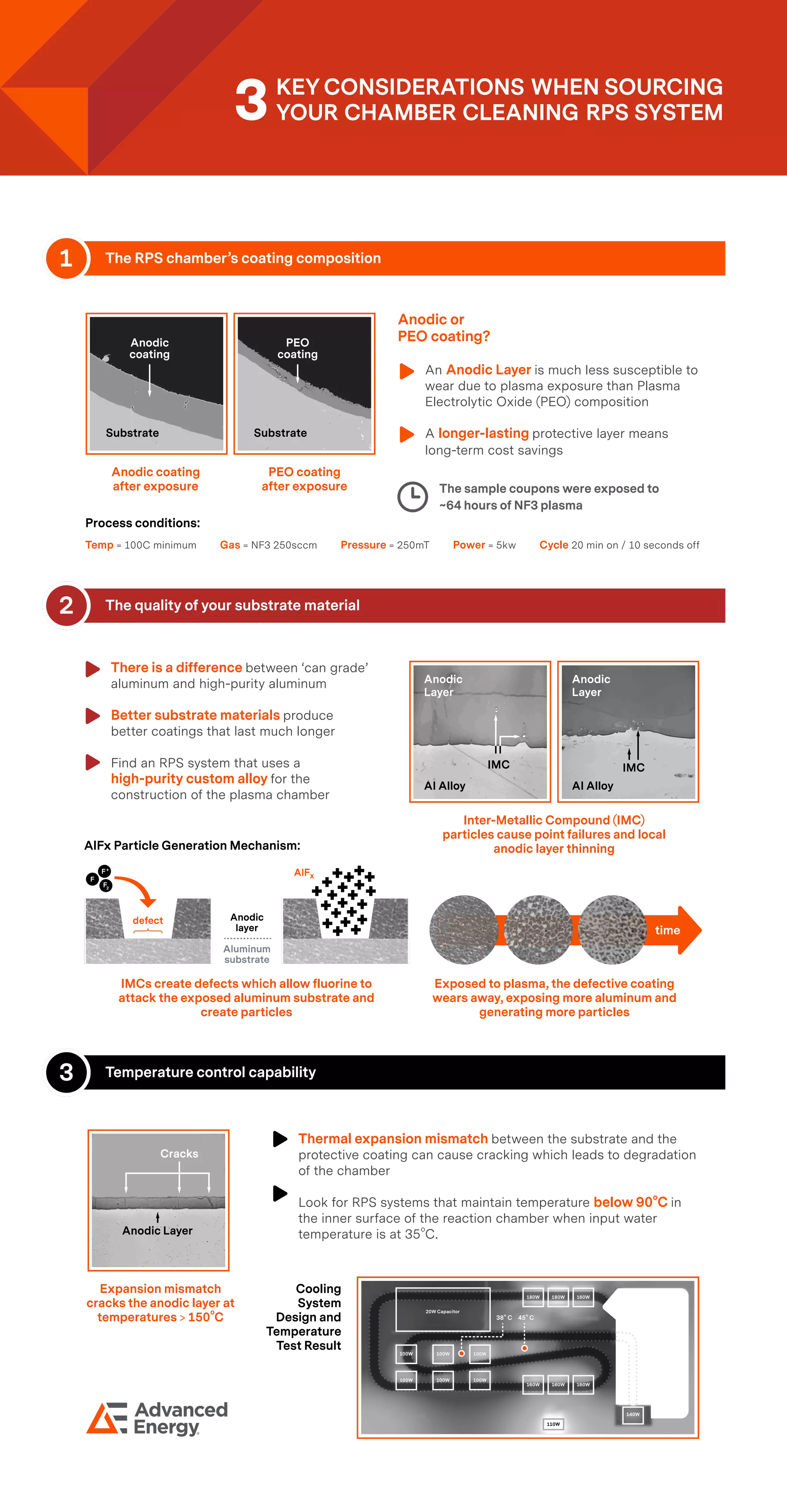

The RPS chamber's anodic coating offers greater wear resistance compared to plasma electrolytic oxide (PEO), resulting in longer-lasting protection and cost savings. The quality of substrate material, particularly high-purity aluminum, significantly impacts coating longevity, while temperature control is crucial to avoid cracks and degradation. Effective RPS systems maintain lower temperatures in the reaction chamber to enhance the performance of anodic coatings against plasma exposure.