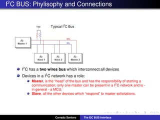
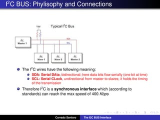
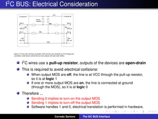
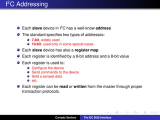
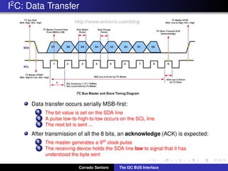
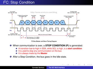
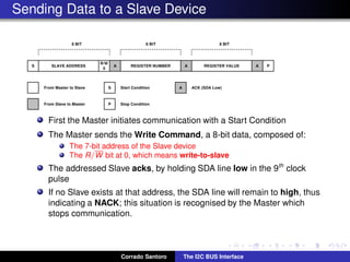
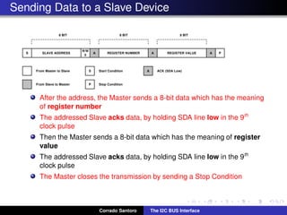
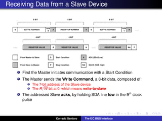
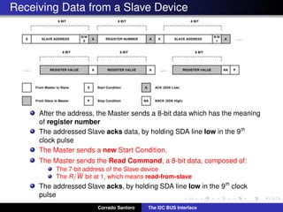
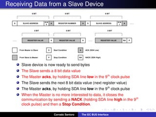
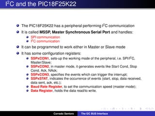
The I2
C BUS Interface
Corrado Santoro
ARSLAB - Autonomous and Robotic Systems Laboratory
Dipartimento di Matematica e Informatica - Universit`a di Catania, Italy
santoro@dmi.unict.it
L.A.P. 1 Course
Corrado Santoro The I2C BUS Interface
What is I2
C?
I2
C Bus or IIC Bus is the acronym for Inter-Integrated Circuit Bus.
It is a standard digital communication bus designed to interconnect
integrated circuits belonging to the same board.
It has been introduced by Philips to interconnect integrated circuits in
TV-sets in the ’80s in the transition from discrete transistors to
integrated-circuits.
The bus has been initially used in TV-sets and VCRs, and then widely
adopted in any integrated device which needs data communication.
Corrado Santoro The I2C BUS Interface
I2
C BUS: Phylisophy and Connections
I2
C has a two wires bus which interconnect all devices
Devices in a I2
C network has a role:
Master, is the “head” of the bus and has the responsibility of starting a
communication; only one master can be present in a I2C network and is -
in general - a MCU;
Slave, all the other devices which “respond” to master solicitations.
Corrado Santoro The I2C BUS Interface
I2
C BUS: Phylisophy and Connections
The I2
C wires have the following meaning:
SDA: Serial DAta, bidirectional; here data bits flow serially (one bit at time)
SCL: Serial CLock, undirectional from master to slaves; it holds the timing
of the transmission
Therefore I2
C is a synchronous interface which (according to
standards) can reach the max speed of 400 Kbps
Corrado Santoro The I2C BUS Interface
I2
C BUS: Electrical Consideration
I2
C wires use a pull-up resistor, outputs of the devices are open-drain
This is required to avoid electrical collisions:
When output MOS are off, the line is at VCC through the pull-up resistor,
so it is at logic 1
If one or more output MOS are on, the line is connected at ground
(through the MOS), so it is at logic 0
Therefore ...
Sending 0 implies to turn-on the output MOS
Sending 1 implies to turn-off the output MOS
Software handles 1 and 0, electrical translation is performed in hardware.
Corrado Santoro The I2C BUS Interface
I2
C Addressing
Each slave device in I2
C has a well-know address
The standard specifies two types of addresses:
7-bit, widely used
10-bit, used only in some special cases
Each slave device has also a register map
Each register is identified by a 8-bit address and a 8-bit value
Each register is used to:
Configure the device
Send commands to the device
Hold a sensed data
etc.
Each register can be read or written from the master through proper
transaction protocols.
Corrado Santoro The I2C BUS Interface
I2
C: Timing and Bus States
BUS IDLE, both SDA and SCL lines are in 1 state.
START CONDITION (S)
A transition high-to-low in SDA, while SCL is high, is a Start Condition
It is used to start communication on the bus
It is always initiated by the Master
Corrado Santoro The I2C BUS Interface
I2
C: Data Transfer
Data transfer occurs serially MSB-first:
1 The bit value is set on the SDA line
2 A pulse low-to-high-to-low occurs on the SCL line
3 The next bit is sent ...
After transmission of all the 8 bits, an acknowledge (ACK) is expected:
1 The master generates a 9th clock pulse
2 The receiving device holds the SDA line low to signal that it has
understood the byte sent
Corrado Santoro The I2C BUS Interface
I2
C: Stop Condition
When communication is over, a STOP CONDITION (P) is generated:
A transition low-to-high in SDA, while SCL is high, is a start condition
It is used to stop any communication on the bus
It is always made by the Master
After a Stop Condition, the bus goes in the Idle state.
Corrado Santoro The I2C BUS Interface
Sending Data to a Slave Device
First the Master initiates communication with a Start Condition
The Master sends the Write Command, a 8-bit data, composed of:
The 7-bit address of the Slave device
The R/W bit at 0, which means write-to-slave
The addressed Slave acks, by holding SDA line low in the 9th
clock
pulse
If no Slave exists at that address, the SDA line will remain to high, thus
indicating a NACK; this situation is recognised by the Master which
stops communication.
Corrado Santoro The I2C BUS Interface
Sending Data to a Slave Device
After the address, the Master sends a 8-bit data which has the meaning
of register number
The addressed Slave acks data, by holding SDA line low in the 9th
clock pulse
Then the Master sends a 8-bit data which has the meaning of register
value
The addressed Slave acks data, by holding SDA line low in the 9th
clock pulse
The Master closes the transmission by sending a Stop Condition
Corrado Santoro The I2C BUS Interface
Receiving Data from a Slave Device
First the Master initiates communication with a Start Condition
The Master sends the Write Command, a 8-bit data, composed of:
The 7-bit address of the Slave device
The R/W bit at 0, which means write-to-slave
The addressed Slave acks, by holding SDA line low in the 9th
clock
pulse
Corrado Santoro The I2C BUS Interface
Receiving Data from a Slave Device
After the address, the Master sends a 8-bit data which has the meaning
of register number
The addressed Slave acks data, by holding SDA line low in the 9th
clock pulse
The Master sends a new Start Condition.
The Master sends the Read Command, a 8-bit data, composed of:
The 7-bit address of the Slave device
The R/W bit at 1, which means read-from-slave
The addressed Slave acks, by holding SDA line low in the 9th
clock
pulse
Corrado Santoro The I2C BUS Interface
Receiving Data from a Slave Device
Slave device is now ready to send bytes
The Slave sends a 8 bit data value
The Master acks, by holding SDA line low in the 9th
clock pulse
The Slave sends the next 8 bit data value (next register value)
The Master acks, by holding SDA line low in the 9th
clock pulse
When the Master is no more interested to data, it closes the
communication by sending a NACK (holding SDA line high in the 9th
clock pulse) and then a Stop Condition.
Corrado Santoro The I2C BUS Interface
I2
C and the PIC18F25K22
The PIC18F25K22 has a peripheral performing I2
C communication
It is called MSSP, Master Synchronous Serial Port and handles:
SPI communication
I2C communication
It can be programmed to work either in Master or Slave mode
It has some configuration registers:
SSPxCON1, sets-up the working mode of the peripheral, i.e. SPI/I2C,
Master/Slave;
SSPxCON2, in master mode, it generates events like Start Cond, Stop
Cond, Ack, NAck;
SSPxCON3, specifies the events which can trigger the interrupt;
SSPxSTAT, indicates the occurrence of events (start, stop, data received,
data sent, ack, etc.);
Baud Rate Register, to set the communication speed (master mode);
Data Register, holds the data read/to write.
Corrado Santoro The I2C BUS Interface
SSP Control Register
ACKSTAT, acknowledge status bit
ACKDT, acknowledge data bit
ACKEN, sends the acknowledge data bit
RCEN, enables the receiver
PEN, initiates a stop condition
RSEN, initiates a repeated start condition
SEN, initiates a start condition
The xxEN bits are automatically cleared by hardware when the operation is
completed
Corrado Santoro The I2C BUS Interface
SSP Status Register
D/A, indicates data or address
P, indicates a detected stop condition
S, indicates a detected start condition
BF, indicates a buffer full condition
During reception: 1 = reception complete
During transmission: 1 = transmission in progress
Corrado Santoro The I2C BUS Interface
Writing a Register through I2
C
✞
int register_write(int dev_address, int reg_number, int reg_value)
{
SSP1CON2bits.SEN = 1; // send a START
while (SSP1CON2bits.SEN == 1) {} // wait for completion
PIR1bits.SSP1IF = 0;
SSP1BUF = dev_address << 1; // shift left in order to include the ‘‘0’’ write bit
while (PIR1bits.SSP1IF == 0) {} // wait for transmission and ack reception
if (SSP1CON2bits.ACKSTAT == 1) { // a NACK is recevied, abort transmission
SSP1CON2bits.PEN = 1; // send a STOP
return 0;
}
PIR1bits.SSP1IF = 0;
SSP1BUF = reg_number;
while (PIR1bits.SSP1IF == 0) {} // wait for transmission and ack reception
if (SSP1CON2bits.ACKSTAT == 1) { // a NACK is recevied, abort transmission
SSP1CON2bits.PEN = 1; // send a STOP
return 0;
}
PIR1bits.SSP1IF = 0;
SSP1BUF = reg_value;
while (PIR1bits.SSP1IF == 0) {} // wait for transmission and ack reception
SSP1CON2bits.PEN = 1; // send a STOP
while (SSP1CON2bits.PEN == 1) {} // wait for STOP completion
return 1;
}
✡✝ ✆
Corrado Santoro The I2C BUS Interface
The I2
C BUS Interface
Corrado Santoro
ARSLAB - Autonomous and Robotic Systems Laboratory
Dipartimento di Matematica e Informatica - Universit`a di Catania, Italy
santoro@dmi.unict.it
L.A.P. 1 Course
Corrado Santoro The I2C BUS Interface

The I2C Interface

  • 1.
    The I2 C BUSInterface Corrado Santoro ARSLAB - Autonomous and Robotic Systems Laboratory Dipartimento di Matematica e Informatica - Universit`a di Catania, Italy santoro@dmi.unict.it L.A.P. 1 Course Corrado Santoro The I2C BUS Interface
  • 2.
    What is I2 C? I2 CBus or IIC Bus is the acronym for Inter-Integrated Circuit Bus. It is a standard digital communication bus designed to interconnect integrated circuits belonging to the same board. It has been introduced by Philips to interconnect integrated circuits in TV-sets in the ’80s in the transition from discrete transistors to integrated-circuits. The bus has been initially used in TV-sets and VCRs, and then widely adopted in any integrated device which needs data communication. Corrado Santoro The I2C BUS Interface
  • 3.
    I2 C BUS: Phylisophyand Connections I2 C has a two wires bus which interconnect all devices Devices in a I2 C network has a role: Master, is the “head” of the bus and has the responsibility of starting a communication; only one master can be present in a I2C network and is - in general - a MCU; Slave, all the other devices which “respond” to master solicitations. Corrado Santoro The I2C BUS Interface
  • 4.
    I2 C BUS: Phylisophyand Connections The I2 C wires have the following meaning: SDA: Serial DAta, bidirectional; here data bits flow serially (one bit at time) SCL: Serial CLock, undirectional from master to slaves; it holds the timing of the transmission Therefore I2 C is a synchronous interface which (according to standards) can reach the max speed of 400 Kbps Corrado Santoro The I2C BUS Interface
  • 5.
    I2 C BUS: ElectricalConsideration I2 C wires use a pull-up resistor, outputs of the devices are open-drain This is required to avoid electrical collisions: When output MOS are off, the line is at VCC through the pull-up resistor, so it is at logic 1 If one or more output MOS are on, the line is connected at ground (through the MOS), so it is at logic 0 Therefore ... Sending 0 implies to turn-on the output MOS Sending 1 implies to turn-off the output MOS Software handles 1 and 0, electrical translation is performed in hardware. Corrado Santoro The I2C BUS Interface
  • 6.
    I2 C Addressing Each slavedevice in I2 C has a well-know address The standard specifies two types of addresses: 7-bit, widely used 10-bit, used only in some special cases Each slave device has also a register map Each register is identified by a 8-bit address and a 8-bit value Each register is used to: Configure the device Send commands to the device Hold a sensed data etc. Each register can be read or written from the master through proper transaction protocols. Corrado Santoro The I2C BUS Interface
  • 7.
    I2 C: Timing andBus States BUS IDLE, both SDA and SCL lines are in 1 state. START CONDITION (S) A transition high-to-low in SDA, while SCL is high, is a Start Condition It is used to start communication on the bus It is always initiated by the Master Corrado Santoro The I2C BUS Interface
  • 8.
    I2 C: Data Transfer Datatransfer occurs serially MSB-first: 1 The bit value is set on the SDA line 2 A pulse low-to-high-to-low occurs on the SCL line 3 The next bit is sent ... After transmission of all the 8 bits, an acknowledge (ACK) is expected: 1 The master generates a 9th clock pulse 2 The receiving device holds the SDA line low to signal that it has understood the byte sent Corrado Santoro The I2C BUS Interface
  • 9.
    I2 C: Stop Condition Whencommunication is over, a STOP CONDITION (P) is generated: A transition low-to-high in SDA, while SCL is high, is a start condition It is used to stop any communication on the bus It is always made by the Master After a Stop Condition, the bus goes in the Idle state. Corrado Santoro The I2C BUS Interface
  • 10.
    Sending Data toa Slave Device First the Master initiates communication with a Start Condition The Master sends the Write Command, a 8-bit data, composed of: The 7-bit address of the Slave device The R/W bit at 0, which means write-to-slave The addressed Slave acks, by holding SDA line low in the 9th clock pulse If no Slave exists at that address, the SDA line will remain to high, thus indicating a NACK; this situation is recognised by the Master which stops communication. Corrado Santoro The I2C BUS Interface
  • 11.
    Sending Data toa Slave Device After the address, the Master sends a 8-bit data which has the meaning of register number The addressed Slave acks data, by holding SDA line low in the 9th clock pulse Then the Master sends a 8-bit data which has the meaning of register value The addressed Slave acks data, by holding SDA line low in the 9th clock pulse The Master closes the transmission by sending a Stop Condition Corrado Santoro The I2C BUS Interface
  • 12.
    Receiving Data froma Slave Device First the Master initiates communication with a Start Condition The Master sends the Write Command, a 8-bit data, composed of: The 7-bit address of the Slave device The R/W bit at 0, which means write-to-slave The addressed Slave acks, by holding SDA line low in the 9th clock pulse Corrado Santoro The I2C BUS Interface
  • 13.
    Receiving Data froma Slave Device After the address, the Master sends a 8-bit data which has the meaning of register number The addressed Slave acks data, by holding SDA line low in the 9th clock pulse The Master sends a new Start Condition. The Master sends the Read Command, a 8-bit data, composed of: The 7-bit address of the Slave device The R/W bit at 1, which means read-from-slave The addressed Slave acks, by holding SDA line low in the 9th clock pulse Corrado Santoro The I2C BUS Interface
  • 14.
    Receiving Data froma Slave Device Slave device is now ready to send bytes The Slave sends a 8 bit data value The Master acks, by holding SDA line low in the 9th clock pulse The Slave sends the next 8 bit data value (next register value) The Master acks, by holding SDA line low in the 9th clock pulse When the Master is no more interested to data, it closes the communication by sending a NACK (holding SDA line high in the 9th clock pulse) and then a Stop Condition. Corrado Santoro The I2C BUS Interface
  • 15.
    I2 C and thePIC18F25K22 The PIC18F25K22 has a peripheral performing I2 C communication It is called MSSP, Master Synchronous Serial Port and handles: SPI communication I2C communication It can be programmed to work either in Master or Slave mode It has some configuration registers: SSPxCON1, sets-up the working mode of the peripheral, i.e. SPI/I2C, Master/Slave; SSPxCON2, in master mode, it generates events like Start Cond, Stop Cond, Ack, NAck; SSPxCON3, specifies the events which can trigger the interrupt; SSPxSTAT, indicates the occurrence of events (start, stop, data received, data sent, ack, etc.); Baud Rate Register, to set the communication speed (master mode); Data Register, holds the data read/to write. Corrado Santoro The I2C BUS Interface
  • 16.
    SSP Control Register ACKSTAT,acknowledge status bit ACKDT, acknowledge data bit ACKEN, sends the acknowledge data bit RCEN, enables the receiver PEN, initiates a stop condition RSEN, initiates a repeated start condition SEN, initiates a start condition The xxEN bits are automatically cleared by hardware when the operation is completed Corrado Santoro The I2C BUS Interface
  • 17.
    SSP Status Register D/A,indicates data or address P, indicates a detected stop condition S, indicates a detected start condition BF, indicates a buffer full condition During reception: 1 = reception complete During transmission: 1 = transmission in progress Corrado Santoro The I2C BUS Interface
  • 18.
    Writing a Registerthrough I2 C ✞ int register_write(int dev_address, int reg_number, int reg_value) { SSP1CON2bits.SEN = 1; // send a START while (SSP1CON2bits.SEN == 1) {} // wait for completion PIR1bits.SSP1IF = 0; SSP1BUF = dev_address << 1; // shift left in order to include the ‘‘0’’ write bit while (PIR1bits.SSP1IF == 0) {} // wait for transmission and ack reception if (SSP1CON2bits.ACKSTAT == 1) { // a NACK is recevied, abort transmission SSP1CON2bits.PEN = 1; // send a STOP return 0; } PIR1bits.SSP1IF = 0; SSP1BUF = reg_number; while (PIR1bits.SSP1IF == 0) {} // wait for transmission and ack reception if (SSP1CON2bits.ACKSTAT == 1) { // a NACK is recevied, abort transmission SSP1CON2bits.PEN = 1; // send a STOP return 0; } PIR1bits.SSP1IF = 0; SSP1BUF = reg_value; while (PIR1bits.SSP1IF == 0) {} // wait for transmission and ack reception SSP1CON2bits.PEN = 1; // send a STOP while (SSP1CON2bits.PEN == 1) {} // wait for STOP completion return 1; } ✡✝ ✆ Corrado Santoro The I2C BUS Interface
  • 19.
    The I2 C BUSInterface Corrado Santoro ARSLAB - Autonomous and Robotic Systems Laboratory Dipartimento di Matematica e Informatica - Universit`a di Catania, Italy santoro@dmi.unict.it L.A.P. 1 Course Corrado Santoro The I2C BUS Interface