Downloaded 290 times
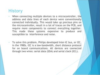
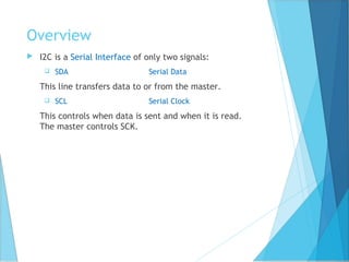
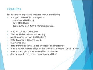
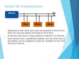
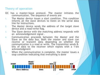
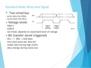
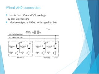
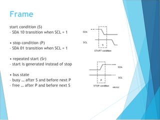
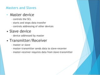
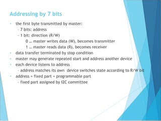
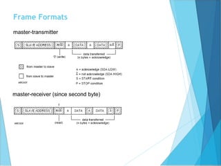

The document discusses the I2C bus, a low-bandwidth, short distance communication protocol developed by Philips in the 1980s to connect multiple devices to a microcontroller using only two wires: serial data (SDA) and serial clock (SCL). It describes I2C's features, such as multiple data speeds, multi-master support, and the master/slave communication model, along with its operational steps for data transfer. The advantages include reduced wiring complexity and costs, while potential drawbacks include inefficiency in simple configurations compared to direct-link interfaces like SPI.