This document is an installation and operation manual for the Neway LSZ13 suspension system. It provides safety instructions, component identification, installation steps, maintenance requirements, and troubleshooting information. Key details include:
- Safety must be followed to prevent injury, such as supporting the vehicle properly, following weight limits, and maintaining proper tire clearance.
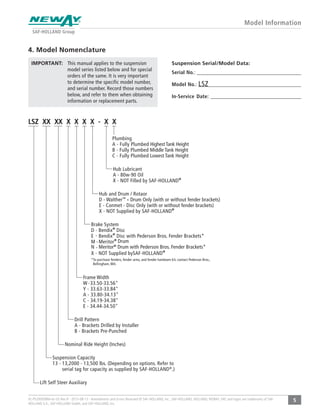
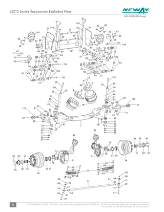
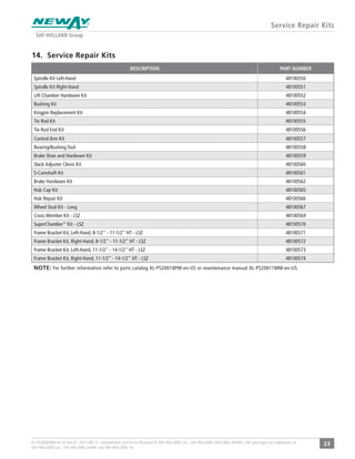
- The manual identifies suspension components and provides exploded views and part numbers.
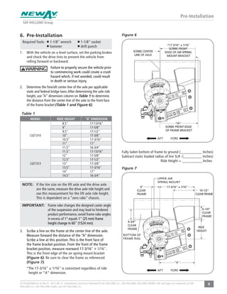
- Installation instructions include pre-installation checks, installation steps, alignment procedures, and pre-operation inspections.
- Maintenance requirements such as torque specifications, lubrication schedules, and routine inspections are outlined.
- Troubleshooting information is provided to address potential issues.