More Related Content
Similar to Service Manual
Similar to Service Manual (20)
Service Manual
- 1. XL-LG11424TS-en-US Rev A · 2012-04-20 · Amendments and errors reserved · © SAF-HOLLAND, Inc.
Figure 2
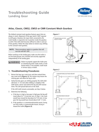
Figure 1
Atlas, Classic, CMS2, CMS3 or CMR Constant Mesh Gearbox
Troubleshooting Guide
Landing Gear
The Holland constant mesh gearbox features gears that are
always in mesh. Alignment of the gear teeth is NOT required
to shift gears. However, the input shaft, connected to the
crank handle, is required to be in position inside the gearbox
to shift. If the shift shaft becomes difficult to slide in and out
of the gearbox, follow the steps below to restore easy shifting
to the constant mesh gearbox.
NOTE: These procedures apply to a gearbox that will
turn but will NOT shift.
Before working on the landing gear, make sure the trailer is
on firm level ground, tires chocked and securely supported
independently of the landing gear.
Failure to properly support the trailer prior
to commencing work could create a crush
hazard which, if not avoided, could result
in serious injury or death.
1. Troubleshooting Procedures
1. Retract the legs two crank turns and then extend them
two crank turns (Figure 1). This motion may loosen the
sticking gear and allow the leg to shift.
2. Verify that the gears are shifting properly. The shift shaft
will move .5" (12 mm) when shifting is complete. If the
shaft moves, retract and extend the leg and shift several
times. This will spread lubricant on the shaft.
If the shift shaft remains unmovable, see Step 3 below.
3. Determine the following:
a. If the leg is in high or low gear. In high gear the leg will
travel about 0.2" (5 mm) per turn. In Step 1, the crank
would have moved the leg about 0.4"(10 mm). In low
gear the leg would have moved about 0.05" (1 mm).
b. If the gearbox is a conventional/outside mount, facing
out from trailer, or reverse/inside mount, facing in
toward the trailer (Figure 2).
RETRACT LEG
EXTEND LEG
CONVENTIONAL/OUTSIDE
MOUNT SHOWN
CONVENTIONAL/OUTSIDE MOUNT
REVERSE/INSIDE MOUNT
- 2. 2 XL-LG11424TS-en-US Rev A · 2012-04-20 · Amendments and errors reserved · © SAF-HOLLAND, Inc.
Troubleshooting Guide
Figure 5
Figure 4
Figure 34. If the leg is in high gear AND the gearbox is a
conventional/outside mount OR
If the leg is in low gear AND the gearbox is a
reverse/inside mount:
Move the shift shaft outward, away from the center of
the trailer. Tap the inside of the shaft to force movement
(Figure 3). To shift completely, the shaft only needs to
move .5" (12 mm). If the shaft does not move turn the
crank a quarter-turn and repeat procedure.
If the leg is in low gear AND the gearbox box is a
conventional/outside mount OR
If the leg is in high gear AND the gearbox is a
reverse/inside mount:
Move the shift shaft inward, toward the center of the
trailer. Tap the outside of the shaft to force movement
(Figure 4). To shift completely, the shaft only needs to
move .5" (12 mm). If the shaft does not move turn the
crank a quarter-turn and repeat procedure
5. Once the shift shaft moves .5" (12 mm), verify that the
gears are shifting properly. Retract and extend the leg and
shift several times. This will spread lubricant on the shaft.
If the gears DO NOT shift after performing the above procedures,
disassemble the gearbox.
2. Gearbox Inspection and Disassembly
NOTE: In the United States, workshop safety requirements
are defined by federal and/or state Occupational
Safety and Health Act. Equivalent laws may exist
in other countries. This manual is written based
on the assumption that OSHA or other applicable
employee safety regulations are followed by the
location where work is performed.
1. Remove any paint and/or dirt from the shafts protruding
from the gearbox (Figure 5). A strip of emery paper or
wire brush should be used to remove any debris build-up
on the shafts.
CONVENTIONAL/OUTSIDE MOUNT REVERSE/INSIDE MOUNT
CONVENTIONAL/OUTSIDE MOUNT REVERSE/INSIDE MOUNT
CONVENTIONAL/OUTSIDE
MOUNT SHOWN
SHAFTS
SELF-TAPPING
SCREWS (7 TOTAL)
- 3. XL-LG11424TS-en-US Rev A · 2012-04-20 · Amendments and errors reserved · © SAF-HOLLAND, Inc. 3
Troubleshooting Guide
Figure 8
Figure 7
Figure 62. Apply a light coat of oil or grease to the cleaned shafts.
3. Remove and retain the seven (7) self-tapping screws that
hold the two gearbox halves together (Figure 5).
4. Insert a pry bar or similar strength device between the
inner and outer gearbox covers at any point on the
gearbox perimeter until separation is visible (Figure 6).
5. With the first pry bar in position, insert a second pry bar
approximately 180 degrees from the first (Figure 7).
6. Using both pry bars, separate the inner and outer covers.
7. Remove the outer cover outward and evenly to ease in
sliding over the shafts (Figure 8). Push the end of the
shaft and rock the cover slightly to aid in removal.
OUTER COVER
INNER COVER
OUTER COVER
- 4. XL-LG11424TS-en-USRevA·2012-04-20·Amendmentsanderrorsreserved·©SAF-HOLLAND,Inc.
SAF-HOLLAND USA, Inc. · 888.396.6501 · Fax 800.356.3929
SAF-HOLLAND Canada Limited · 519.537.3494 · Fax 800.565.7753
Western Canada · 604.574.7491 · Fax 604.574.0244
SAF-HOLLAND Mexico · +(52) 55.5362.8743 · Fax +(52) 55.5362.8743
www.safholland.us
Troubleshooting Guide
The shift shaft and input gears may move with the cover
(Figure 9). During removal of the cover the idler gear
assembly of the Atlas or CMS3 will come loose (Figure 10).
Remove the idler gear assembly to prevent it from falling
out once the inner and out covers are far enough apart.
NOTE: If the idler gear falls out, closely inspect the gear
for any visible damage. Replace if necessary.
8. Once the cover is removed, the shift shaft, and the low
and high input gears may be removed. Make sure to note
the order the gears are removed for reassembly. Remove
all gears from the shaft (Figure 10).
9. Use a wire brush to clean and remove any debris from
the inner bore of both gears and the exterior of the shaft.
10. Apply a coating of grease or light oil to the clean interior
of the gears and the exterior of the shaft. Slide the gears
on the shaft in the same order as they were removed.
If the gears will NOT slide onto the shaft in the region of
the pin, replace the shaft, pin, and both gears. Refer to
the Holland Landing Gear Parts Manual, XL-LG11389-PM
to identify the correct parts.
11. Install the pin in the shaft. Apply a light coat of oil or
grease to the exterior of the shaft and interior of the
gears and slide the gears on the shaft.
12. Reassemble the gearbox.
3. Gearbox Reassembly
1. Check the inner and outer cover of the gearbox and
form-in-place gasket for damage. Repair or replace if
damage is excessive.
2. Assemble the shafts and idler gear (if applicable) to the
inside of the outer gearbox cover. Be sure to assemble
the gears in the order in which they were removed.
NOTE: If the gears are not assembled correctly, the outer
gearbox cover will not align properly with the
inner cover.
3. Apply a light coating of oil or grease to the shafts.
4. Slide the outer cover over the shafts evenly.
5. Install the seven (7) self-tapping screws to attach the
gearbox covers together. The screws should be tightened
6. Add one-half pound of a good quality grease with the
appropriate service temperature range to the gearbox.
For low temperature operation (under 20° F / -6° C) use
a lithium or an anhydrous calcium extreme pressure
grease that operates down to -65° F / -53° C.
Figure 9
Figure 10
IDLER GEAR
OUTPUT GEAR
LOW GEAR
HIGH GEARINNER
COVER
OUTER COVER
SELF-TAPPING SCREWS