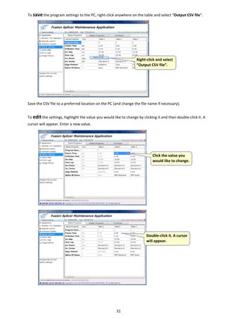
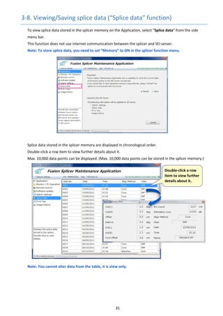
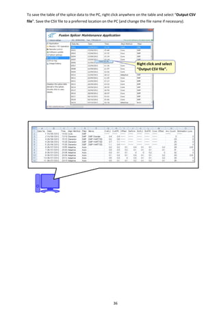
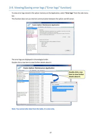
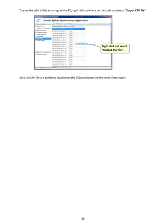
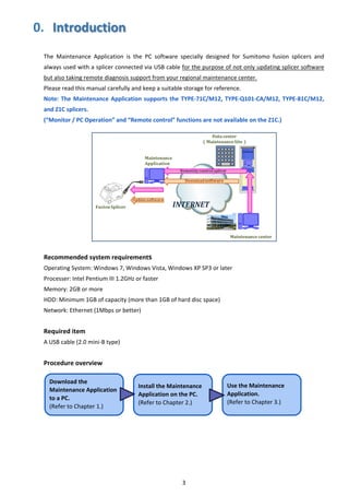
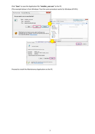
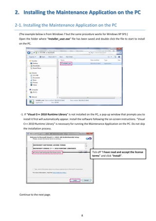
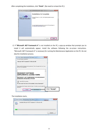
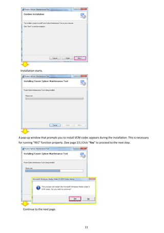
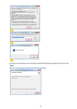
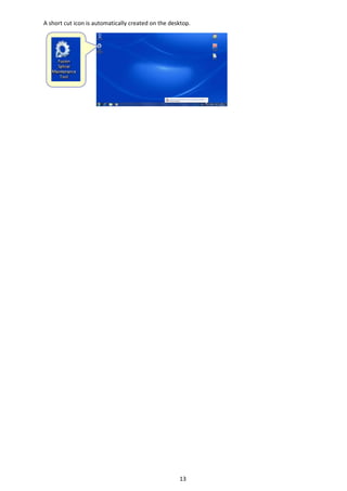
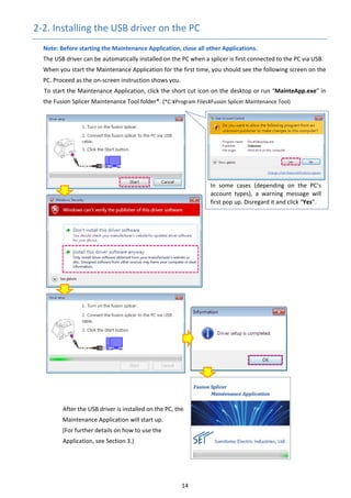
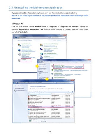
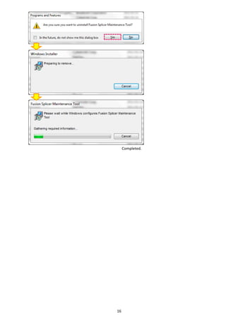
ETK1124100C
For Sumitomo Fusion Splicer 
 Maintenance Application
User Guide 
1 
END-USER LICENSE AGREEMENT FOR SOFTWARE
PLEASE READ THE TERMS AND CONDITIONS OF THIS LICENSE AGREEMENT CAREFULLY
BEFORE CONTINUING WITH THIS PROGRAM INSTALL:
Sumitomo Electric Industries, Ltd. (hereafter SEI)'s End-User License Agreement ("EULA") is a legal agreement
between you (either an individual or a single entity) and SEI. By installing, copying, or otherwise using the software,
you agree to be bound by the terms of this EULA. This license agreement represents the entire agreement concerning
the program between you and SEI, (referred to as "licenser"), and it supersedes any prior proposal, representation, or
understanding between the parties. If you do not agree to the terms of this EULA, do not install or use the software.
The software is protected by copyright laws and international copyright treaties, as well as other intellectual property
laws and treaties. The software is licensed, not sold.
1. GRANT OF LICENSE.
The software is licensed as follows:
(a) Installation and Use.
SEI grants you the right to install and use copies of the software on your computer running a validly licensed copy
of the operating system.
(b) Backup Copies.
You may also make copies of the software as may be necessary for backup and archival purposes.
2. DESCRIPTION OF OTHER RIGHTS AND LIMITATIONS.
(a) Maintenance of Copyright Notices.
You must not remove or alter any copyright notices on any and all copies of the software.
(b) Prohibition on Reverse Engineering, Decompilation, and Disassembly.
You may not reverse engineer, decompile, or disassemble the software, except and only to the extent that such
activity is expressly permitted by applicable law notwithstanding this limitation.
(c) No Support Services.
You may not use the software with fusion splicer outside the area where you are allowed to use. If you use
the fusion splicer in the area not allowed, the software stops running and disconnects it from SEI server
automatically.
(d) Compliance with Applicable Laws.
You must comply with all applicable laws regarding use of the software.
3. TERMINATION
Without prejudice to any other rights, SEI may terminate this EULA if you fail to comply with the terms and
conditions of this EULA. In such event, you must destroy all copies of the software in your possession.
4. COPYRIGHT
All title, including but not limited to copyrights, in and to the software and any copies thereof are owned by SEI or
its suppliers. All title and intellectual property rights in and to the content which may be accessed through use of the
software is the property of the respective content owner and may be protected by applicable copyright or other
intellectual property laws and treaties. This EULA grants you no rights to use such content. All rights not expressly
granted are reserved by SEI.
5. NO WARRANTIES
SEI expressly disclaims any warranty for the Software. SEI does not warrant or assume responsibility for the
accuracy or completeness of any information, text, graphics, links or other items contained within the software. SEI
makes no warranties respecting any harm that may be caused by the transmission of a computer virus, worm, time
bomb, logic bomb, or other such computer program. SEI further expressly disclaims any warranty or representation
to Authorized Users or to any third party.
6. LIMITATION OF LIABILITY
In no event shall SEI be liable for any damages (including, without limitation, lost profits, business interruption, or
lost information) rising out of 'Authorized Users' use of or inability to use the software, even if SEI has been
advised of the possibility of such damages. In no event will SEI be liable for loss of data or for indirect, special,
incidental, consequential (including lost profit), or other damages based in contract, tort or otherwise. SEI shall
have no liability with respect to the content of the software or any part thereof, including but not limited to errors or
omissions contained therein, libel, infringements of rights of publicity, privacy, trademark rights, business
interruption, personal injury, loss of privacy, moral rights or the disclosure of confidential information.
2 
Contents 
  Page 
0. Introduction  3 
1. Downloading the Maintenance Application  4 
    1‐1. Visual C++ 2010 Runtime Library / Microsoft .NET Framework 4  4 
    1‐2. Logging in to Maintenance Application download page  5 
    1‐3. Downloading the Maintenance Application  6 
2. Installing the Maintenance Application on the PC  8 
    2‐1. Installing the maintenance Application on the PC  8 
    2‐2. Installing the USB driver on the PC  14 
    2‐3. Uninstalling the Maintenance Application  15 
3. Using the Maintenance Application  18 
    3‐1. Starting the Maintenance Application  18 
    3‐2. Exiting the Maintenance Application  20 
    3‐3. Maintenance Application function  21 
    3‐4. Operating the splicer from the PC (“Monitor / PC Operation” function)  22 
    3‐5. Remote diagnosis by Service center (“Remote control” function)  25 
    3‐6. Updating the splicer software (“Software update” function)  28 
    3‐7. Viewing/saving/editing/copying splicer’s settings (“Splicer settings” function)  30 
    3‐8. Viewing/saving splice data (“Splice data” function)  35 
    3‐9. Viewing/saving error log (“Error log” function)  37 
    3‐10. Viewing/saving fiber images (“Image history” function)  39 


 Microsoft, Windows, Internet Explorer, Visual C++, .NET Framework, Windows Media are either 
registered trademarks or trademarks of Microsoft Corporation in the United States and/or other 
countries. 
 Intel and Pentium are either registered trademarks or trademarks of Intel Corporation or its subsidiaries 
in the United States and/or other countries. 
 Ethernet is a registered trademark of Xerox Corporation. 
   
3 
0.  Introduction
 
The  Maintenance  Application  is  the  PC  software  specially  designed  for  Sumitomo  fusion  splicers  and 
always used with a splicer connected via USB cable for the purpose of not only updating splicer software 
but also taking remote diagnosis support from your regional maintenance center. 
Please read this manual carefully and keep a suitable storage for reference. 
Note: The Maintenance Application supports the TYPE‐71C/M12, TYPE‐Q101‐CA/M12, TYPE‐81C/M12, 
and Z1C splicers. 
(“Monitor / PC Operation” and “Remote control” functions are not available on the Z1C.) 
 
Recommended system requirements 
Operating System: Windows 7, Windows Vista, Windows XP SP3 or later 
Processer: Intel Pentium III 1.2GHz or faster 
Memory: 2GB or more 
HDD: Minimum 1GB of capacity (more than 1GB of hard disc space) 
Network: Ethernet (1Mbps or better) 
 
Required item 
A USB cable (2.0 mini‐B type) 
 
Procedure overview 


Download the 
Maintenance Application 
to a PC. 
(Refer to Chapter 1.) 
Install the Maintenance 
Application on the PC. 
(Refer to Chapter 2.) 
Use the Maintenance 
Application. 
(Refer to Chapter 3.) 
4 
1.   Downloading the Maintenance Application 
1‐1. Visual C++ 2010 Runtime Library / Microsoft .NET Framework 4   
To use the Maintenance Application, Visual C++ 2010 Runtime Library and Microsoft .NET Framework 4 
are required. 
 
<Visual C++ 2010 Runtime Library> 
If Visual C++ 2010 Runtime Library is not installed on the PC, the installer for the Visual C++ 2010 Runtime 
Library automatically starts before the Maintenance application is installed. For more information, please 
see page 8~9. 
 
<Microsoft .NET Framework 4> 
First make sure that the PC has the Microsoft .NET Framework 4 installed. And if not, download it from 
Microsoft web site. 
(English version: http://www.microsoft.com/download/en/details.aspx?id=17718 ) 
Even If you start installing the Maintenance Application without the Microsoft .NET Framework 4 installed, 
a pop‐up window will appear prompting you to install it first before installing the Maintenance Application. 
(For more information, see page 9.) 


5 
1‐2. Logging in to Maintenance Application download page 
To download the Maintenance Application, open your web browser and go to Sumitomo internet service 
system  web  site  http://www.rim‐plus.sei.co.jp/.  (The  web  site  address  is  also  stated  in  the  splicer 
operation manual.) Scroll down the page and click the link in the Download section.
 
The Login page is displayed. You are required to enter the serial number (12 digits) of the splicer you have. 
Then click “Login”. 


Enter the serial number (12 digits.) 
Click “Login”. 
Click this link. 
6 
1‐3. Downloading the Maintenance Application 
The  Maintenance  Application  download  page  is  displayed.  Click  the  link  in  the  page  to  download  the 
Application file. 
Note:  The  Maintenance  Application  file  is  common  for  the  TYPE‐71C/M12,  TYPE‐Q101‐CA/M12, 
TYPE‐81C/M12 and Z1C splicers.
“END‐USER LICENSE AGREEMENT FOR SOFTWARE” is displayed. Click “Agree”. 


Click this link. 
Click “Agree”. 
Scroll down 
7 
Click “Save” to save the Application file “installer_user.exe” to the PC. 
(The example below is from Windows 7 but the same procedure works for Windows XP SP3.) 


Proceed to install the Maintenance Application on the PC. 


8 
2.  Installing the Maintenance Application on the PC 
2‐1. Installing the Maintenance Application on the PC 
(The example below is from Windows 7 but the same procedure works for Windows XP SP3.) 
Open the folder where “Installer_user.exe” file has been saved and double click the file to start to install 
on the PC. 


‐1. If “Visual C++ 2010 Runtime Library” is not installed on the PC, a pop‐up window that prompts you to 
install it first will automatically appear. Install the software following the on‐screen instructions. “Visual 
C++ 2010 Runtime Library” is necessary for running the Maintenance Application on the PC. Do not skip 
the installation process. 


Continue to the next page. 


Tick off “I have read and accept the license 
terms” and click “Install”. 
9 
After completing the installation, click “Finish”. (No need to re‐boot the PC.) 


‐2. If “Microsoft .NET Framework 4” is not installed on the PC, a pop‐up window that prompts you to 
install  it  will  automatically  appear.  Install  the  software  following  the  on‐screen  instructions. 
“Microsoft .NET Framework 4” is necessary for running the Maintenance Application on the PC. Do not 
skip the installation process. 


The installation starts. 


Click “Accept”. 
10 
After the installation is completed, the Maintenance Application installer automatically appears. Follow the 
on‐screen instructions to install. 


Select “I Agree”. 
Continue to the next page. 
11 


Installation starts. 


A pop‐up window that prompts you to install VCM codec appears during the installation. This is necessary 
for running “REC” function properly. (See page 23.) Click “Yes” to proceed to the next step. 


Continue to the next page. 
12 


If you see the screen below, you’ve successfully installed the Maintenance Application on the PC. Click 
“Close”. 
Note: It is not necessary to reboot the PC after the installation. 
   
13 
A short cut icon is automatically created on the desktop. 


14 
2‐2. Installing the USB driver on the PC 
Note: Before starting the Maintenance Application, close all other Applications. 
The USB driver can be automatically installed on the PC when a splicer is first connected to the PC via USB. 
When you start the Maintenance Application for the first time, you should see the following screen on the 
PC. Proceed as the on‐screen instruction shows you. 
To start the Maintenance Application, click the short cut icon on the desktop or run “MainteApp.exe” in 
the Fusion Splicer Maintenance Tool folder*. (*C:¥Program Files¥Fusion Splicer Maintenance Tool) 


After the USB driver is installed on the PC, the     
Maintenance Application will start up. 
(For further details on how to use the 
Application, see Section 3.) 
 
   
In  some  cases  (depending  on  the  PC’s 
account  types),  a  warning  message  will 
first pop up. Disregard it and click “Yes”. 
15 
2‐3. Uninstalling the Maintenance Application 
If you do not need the Application any longer, carry out the uninstallation procedure below. 
Note: It is not necessary to uninstall an old version Maintenance Application before installing a newer 
version one. 
 
<Windows 7 > 
Click  the  Start  button.  Select  “Control  Panel”  >  “Programs”  >  “Programs  and  Features”.  Select  and 
highlight “Fusion Splicer Maintenance Tool” from the list of “Uninstall or change a program”. Right click it 
and select “Uninstall”. 


16 


Completed. 
17 
<Windows XP SP3> 
Click the Start button. Select “Control Panel” > “Add or Remove program”. Select and highlight “Fusion 
Splicer Maintenance Tool”. Click “Remove”. 


Completed. 
18 
3.   Using the Maintenance Application 
3‐1. Starting the Maintenance Application 
Note: Before starting the Maintenance Application, close all other Applications. Make sure that internet 
connection is available. 
Start  the  Application  by  clicking  the  short  cut  icon  on  the  desktop  or  running  “MainteApp.exe”  in  the 
Fusion Splicer Maintenance Tool folder*. (*C:¥Program Files¥Fusion Splicer Maintenance Tool) 
Referring to the on‐screen instructions, switch on the splicer and connect the splicer with the PC via USB 
cable.   


While the Maintenance Application window is displayed, the splicer is 
verified via internet in the background. 
Note: If the connection between the splicer and Application fails, an           
error message will appear. Reboot the splicer and try again. 


When  the  Application can detect the fusion splicer and receive 
the  information  from  the  splicer  correctly,  the  start  screen  is 
displayed. 
 
Caution: If the Maintenance Application has an access out of     
the sales area which is set in the splicer, a message shown below 
appears. To proceed to start the Application, Click “OK”. The 
Application can be 
used but Software 
update and 
Remote control 
functions have a 
limitation on the 
number of access. 
 
Start screen 
Maintenance Application window
19 
<Maintenance Application Start Screen> 


<IMPORTANT> 
Before updating software on the splicer or taking remote control support by service center, select “Permit”, 
the Maintenance Application can send the current state of the splicer to the SEI server via internet.   


Fusion splicer software update indicator 
        The current software version is the latest. 
        (No need to update.) 
        New software version is available. 
S/N verification indicator 
        The serial number is verified correctly by the SEI server via internet. 
 
        The serial number is not verified by the SEI server via internet. 
Side menu bar 
When  you  select  a 
function,  the  screen  of 
the function appears on 
the right side screen. 
(For  further  details  on 
each function, see page 
21~40.) 
If a function is selected, 
the  description  of  the 
function  is  displayed  in 
this pane. 
Network settings 
If  you  need  proxy  server  settings, 
click this icon and do the settings. 
 
  Select  “Permit”  before  updating 
the  software  or  taking  remote 
control support.   
To  upload  the  splicer  settings, 
splice data, error logs and images 
stored  in  the  splicer  to  the  SEI 
server, click “Upload”. This may be 
useful  for  service  center  that  will 
carry out remote control. 
 
20 
If the data upload is successful, a pop‐up window shown below will tell this to you. 


If the data upload fails, a pop‐up window shown below tell this to you. If the problem still persists after 
some trials, contact your regional service center. 


3‐2. Exiting the Maintenance Application 
To exit the Maintenance Application, Click the “X”. 


Click “X”. 
21 
3‐3. Maintenance Application Functions 
The Maintenance Application has various functions. Select a function from the side menu bar. 
 
<Functions> 
Application: See page 19~20. 
 
Monitor / PC Operation: Displays the splicer 
touchscreen and operate the splicer on the Application. 
Arc test process and splicing process can be recorded 
for a video file. (The function is not available on Z1C.) 
(See page 22~24.) 
 
Remote control: Connects to service center via internet 
and have the splicer diagnosed remotely if it has any 
problems. (The function is not available on Z1C.) 
(See page 25~27.) 
*The remote control service is only available for           
TYPE‐71C, TYPE‐Q101‐CA and TYPE‐81C as of March 
2013. 
 
Software update: Updates the splicer software via internet. 
(See page 28~29.) 
 
Splicer settings: Displays the settings the splicer has, such as splice program, arc parameter and etc. 
You can also edit and output the settings in CSV format to the PC. 
(See page 30~34.) 
 
Splice data: Displays splice data stored in the splicer memory. 
You can also output the splice data in CSV format to the PC. 
(See page 35~36.) 
 
Error logs: Displays error logs stored in the splicer memory. 
You can also output the error logs in CSV format to the PC. 
(See page 37~38.) 
 
Image history: Displays fiber images stored in the splicer memory. 
You can also save the images in JPG format to the PC. 
(See page 39~40.) 


22 
3‐4. Operating the splicer from the PC (“Monitor / PC Operation” function) 
This function enables to have the splicer monitor screen displayed and operate the fusion splicer on the PC. 
You can perform an arc test, the splicing and the heat shrink processes by clicking the on‐screen icons. 
This function does not use internet communication between the splicer and SEI server. 
 
Note: Before performing an arc test and the splicing process, load fiber in the splicer and select suitable 
splice program for the fiber from the pull down menu. 
          Before performing the heat shrink process, place a protection sleeve with the splice onto the heat 
shrink oven and select a suitable heater program for the sleeve from the pull down menu.   


Note: While this function is used, the splicer shows the globe icon. If the Ready screen appears on the 
splicer after resetting it and you would like to continue to use the function, get out of “Monitor / 
PC Operation” by selecting “Application” and then select “Monitor / PC Operation” again. 


 Click this icon to start the 
splicing process or an arc test.
 Click this icon to 
start/cancel* the heat 
shrink process on the 
rear oven. 
 Click this icon to 
reset the splicer. 
 
Click this icon to 
start/cancel* the heat 
shrink process on the 
front oven. 
*Start: Click once 
Cancel: Click twice 
 Click this icon go to 
arc test mode. 
 Select a suitable 
splice program from 
the pull down menu.
 Select a suitable 
heater program from 
the pull down menu. 
 Record splicing process 
and arc test process. 
For more information, 
see page 23. 
23 
Recording function 
You can record splicing process and arc test process and save as a video file on the PC. 
If you would like to record arc test process, click        in advance to enter the Arc Test mode. 
Click          . Save as screen will pop up, asking you to select what location (on the PC) to save the video file. 
The name of the file is linked to the date and time. You can also edit it as you like. Click “Save”. 
Note: The video file format is “.avi” only. Estimated loss, cleave angle etc are not saved in the video. 
Click        .  Splicing  process  or  arc  test  process  will  start.  After  the  process  is  finished,  the  video  file  is 
automatically created in the location you selected. 
Note: The recording time is max. 60 seconds.
After the splicing process or arc test process is completed, recording is also completed and a message 
window to tell you completion of recording appears. Click “OK”.   


 Select what location (on the PC) 
to save the video file. 
Click                  . 
 Click              .
  Click              .
 
When                  is displayed above the REC 
 
icon, the Application starts recording and 
countdown of 60 seconds in the background.
24 
Following the message, you will be asked if you would like to upload the video file to the SEI server for 
future reference for your regional service center. Click “Yes” or “No”. 


Note: If an error occurs or “Reset” icon is clicked during recording, the recording is finished at the time 
and the file of the video which was recorded part way through is created. 
 
The video file is automatically created in the location you selected. It can be opened with “Windows Media 
Player” or other players. 
Fiber images in the video file are captured directly from the CMOS camera and there is no mention of “X” 
and “Y” fields. You can interpret the images as follows. 


Y  X 
25 
3‐5. Remote diagnosis by Service center (“Remote control” function”) 
This function enables to connect the fusion splicer to service center via the SEI server and have the splicer 
diagnosed remotely if it has any problem. 
*The remote control service is only available for TYPE‐71C, TYPE‐Q101‐CA and TYPE‐81C as of March 2013. 
Note: It is recommended that you contact your regional service center and arrange schedule before 
taking the service. At the same time inform them of splicer’s S/N, problem found, etc. 
It uses internet communication between the splicer and SEI server. Ensure that “Permit” for the Important 
notice is selected on the start screen. (Refer to page 19.) Select “Remote control” from the side menu bar. 


As soon as selecting “Remote control” from the side menu bar, a pop‐up window that asks you if you 
would like to start remote control appears. Click “Yes”. 


This  will  allow  the  splicer  to  get  connected  to  the  SEI  server  for  remote  control  and  “Permit”  on  the 
Remote control screen is automatically selected. To prevent accidental incorrect operation during remote 
control, other functions are disabled temporarily. 


Select “Permit”. 
“Permit” is automatically selected. 
26 
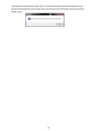
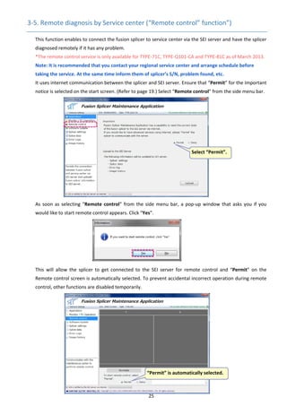
Note: Selecting “Deny” before remote control means cancellation of the remote control and all other 
functions are enabled again. If you select “Deny” during remote control, the remote control will be 
terminated. 
 
For  Windows  7  and  Vista,  if  “Aero”  feature  is 
enabled,  the  information  window  will  appear. 
With the feature enabled, your PC desktop will 
happen  to  be  shown  on  the  maintenance 
center’s  computer.  To  proceed  to  the  remote 
control,  click  “Yes”.  The  Aero  feature  will  be 
disabled temporarily during the remote control. 
(And it is automatically enabled again after the 
remote control.) If you select “No”, the remote control is cancelled.   
For details on the “Aero” feature, refer to 
http://windows.microsoft.com/en‐US/windows7/products/features/aero (English site). 
 
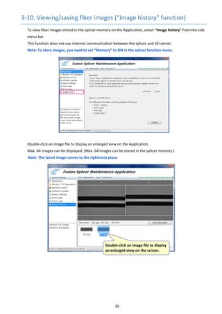
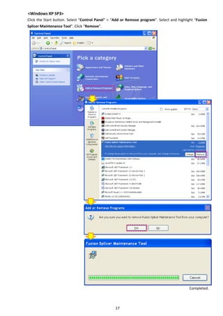
After you’ve done up to this step, contact them to tell that you’re ready. Once the service center accept 
the  splicer  and  are  ready  to  diagnose  it,  the  fiber  image  observed  by  the  splicer  is  displayed  on  the 
Maintenance Application and the screen image of the Maintenance Application will be sent to the service 
center via the server. 
Note: While the remote control is conducted, the splicer shows the globe icon. If it does not show the 
icon, from the menu screen on the splicer, manually select [USB]‐[Remote Diagnosis]. 


The service center will remotely control and diagnose the splicer. Wait for a while. 
Caution: Do not disconnect the USB and internet connection during the remote control. It is 
recommended that AC power be used rather than batteries to prevent from running out of power. 


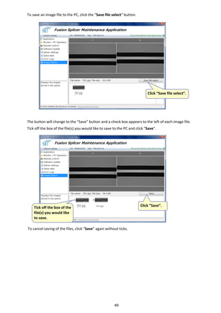
 You can type messages you 
would  like  to  tell  to  the 
maintenance  center  during 
the remote control. 
The  center  can  view  the 
messages as they are. 
27 
To terminate the remote control, select “Deny”. The internet connection will be disconnected. Or it can 
also be disconnected by the service center. When the remote control is terminated, the splicer shows the 
“Ready” screen. 
   
28 
3‐6. Updating the splicer software (“Software update” function) 
When the software update indicator icon is        on the start screen, you can update the software on the 
splicer. 
This function uses internet communication between the splicer and SEI server. 
Ensure that “Permit” for the Important notice is selected on the start screen. (Refer to page 19.) 
      Then select “Software Update” from the side menu bar. 


      Check the software versions displayed on the Application and click the “Update” button to start the update. 
Wait until the green progress bar moves to the right. 


Caution: Do not disconnect the USB and internet connection during the software update. It is 
recommended that AC power be used rather than batteries to prevent from running out of power. 
   
 The current software version is the 
latest. (No need to update.) 
 
New version software is available.
Select “Permit”. 
 Click “Update”. 
29 
After the software update is completed, the splicer will shut down automatically. A message window that 
tells you that the Maintenance Application will be closed appears. Click “OK”. 


Turn on the splicer and go to “Information” from the menu screen. Ensure that the software has been 
updated. 
 
Note: If you fail to update the software, reboot the PC and try again. 
 
 
Note: From software version 1.152, a message that prompts you to install Persian font on the PC is 
displayed from the next start‐up of the Maintenance Application. If you need the font, click “Font 
update”. If you don’t need, disregard the message. The font update does not affect the splicer operating 
system. 
Even if the Persian font is installed, it may not be displayed depending on the splicers. 
   
30 
3‐7. Viewing/saving/editing/copying splicer’s settings (“Splicer settings” function) 
      To view the settings of the splicer connected on the Application, select “Splicer settings” from the side 
menu bar. 
This function does not use internet communication between the splicer and SEI server. 
Splice programs/Heater programs/Function settings stored in the fusion splicer are displayed. 


Click the tab of “Splice 
Program”, “Heater 
Program” or “Function” 
you would like to view. 
31 
To save the program settings to the PC, right‐click anywhere on the table and select “Output CSV file”. 


Save the CSV file to a preferred location on the PC (and change the file name if necessary). 
 
To edit the settings, highlight the value you would like to change by clicking it and then double‐click it. A 
cursor will appear. Enter a new value. 


 Right‐click and select 
“Output CSV file”. 
 Click the value you 
would like to change.
 Double‐click it. A cursor 
will appear. 
32 
Note: When you place your mouse pointer over the value, you can see the range of allowable values. 


Click anywhere else after entering the new value. The new value is fixed in the data table and the change 
made is saved in the splicer memory in synchronization. You can edit the settings while looking at the 
program screen on the splicer monitor. If you move to other screen from the current screen and come 
back to the screen which was shown previously, you can see the change. 


Caution: Splice/Heater program settings for various fiber profiles pre‐loaded in the splicer are optimized 
before shipment and such optimization requires professional knowledge. We cannot guarantee that the 
settings you edited can result in high splice losses, failure of splicing/heat shrinking etc. 
If you would like to return the edited settings to the factory default, from the splicer’s menu select 
“Maintenance”‐“Restore Data (2/2 page)”. 


The new value is fixed 
and saved in the splicer 
memory. 
33 
“Align Method” and functions have pull‐down options. Highlight the current option of an item you would 
like to change by clicking it. Then double‐click it. Options appear on pull down menu. 


Click anywhere else after changing the settings. The newly selected option is fixed in the data table and the 
change made is saved in the splicer memory in synchronization. You can change the settings while looking 
at the function screen on the splicer monitor. If you move to other screen from the current screen and 
come back to the screen which was shown previously, you can see the change. 


 Click the current option 
of a function you would 
like to change. 
 
Double‐click it. Options 
appear on pull down 
menu. 
 
The new setting is 
fixed and saved in the 
splicer memory. 
34 
You can also copy splice/heater program settings to blank program areas. Click the Data number you 
would like to copy. The values and items for the Data number will be all highlighted. Right‐click anywhere 
in the highlight, and select “Copy”. 


Program data window will pop up. Before copying, you can change the program number of area to copy 
the data to, and even change the value and edit the program label. Click “OK” when you’re ready. 
Note: Blank program areas are, 
      For TYPE‐71C, TYPE‐Q101‐CA, TYPE‐81C, Z1C 
>>>Splice program: No. 101~300, Heater program: No. 51~100 
For TYPE‐71M12, TYPE‐Q101‐M12, TYPE‐81M12 
>>>Splice program: No. 101~200, Heater program: No. 71~100 
 
Note: The following splice programs cannot be copied and edited.   
For TYPE‐71C, TYPE‐Q101‐CA, TYPE‐81C, Z1C 
>>> Data 1 (Auto) 
For TYPE‐71M12, TYPE‐Q101‐M12, TYPE‐81M12 
>>> Data 1 (SM: Auto), Data 2 (MM: Auto), Data 3 (DS/NZ: Auto) 
 
The splice program is copied to the designated blank area. 


Note: Once data are copied, they cannot be deleted. 
 Click the Data number. 
Right‐click and select 
“Copy”. 
35 
3‐8. Viewing/Saving splice data (“Splice data” function) 
To view splice data stored in the splicer memory on the Application, select “Splice data” from the side 
menu bar.
This function does not use internet communication between the splicer and SEI server. 
Note: To store splice data, you need to set “Memory” to ON in the splicer function menu.
Splice data stored in the splicer memory are displayed in chronological order. 
Double‐click a row item to view further details about it. 
Max. 10,000 data points can be displayed. (Max. 10,000 data points can be stored in the splicer memory.) 
Note: You cannot alter data from the table, it is view only. 
 
   
 Double‐click a row 
item to view further 
details about it. 
36 
To save the table of the splice data to the PC, right click anywhere on the table and select “Output CSV 
file”. Save the CSV file to a preferred location on the PC (and change the file name if necessary). 
 Right click and select 
“Output CSV file”. 
37 
3‐9. Viewing/Saving error logs (“Error logs” function) 
To view error logs stored in the splicer memory on the Application, select “Error logs” from the side menu 
bar.
This function does not use internet communication between the splicer and SEI server.


The error logs are displayed in chronological order. 
Double‐click a row item to view further details about it. 


Note: You cannot alter data from the table, it is view only. 
 
   
 Double‐click a row 
item to view further 
details about it. 
38 
To save the table of the error logs to the PC, right click anywhere on the table and select “Output CSV file”. 


Save the CSV file to a preferred location on the PC (and change the file name if necessary). 
   
 Right click and select 
“Output CSV file”. 
39 
3‐10. Viewing/saving fiber images (“Image history” function) 
To view fiber images stored in the splicer memory on the Application, select “Image history” from the side 
menu bar.
This function does not use internet communication between the splicer and SEI server. 
Note: To store images, you need to set “Memory” to ON in the splicer function menu.


Double‐click an image file to display an enlarged view on the Application. 
Max. 64 images can be displayed. (Max. 64 images can be stored in the splicer memory.) 
Note: The latest image comes to the rightmost place. 


 Double‐click an image file to display 
an enlarged view on the screen. 
40 
To save an image file to the PC, click the “Save file select” button. 


The button will change to the “Save” button and a check box appears to the left of each image file. 
Tick off the box of the file(s) you would like to save to the PC and click “Save”. 


To cancel saving of the files, click “Save” again without ticks. 


Click “Save file select”.
502.jpg
 Tick off the box of the 
file(s) you would like 
to save. 
Click “Save”. 
41 
Original issued March 2012 (for Maintenance Application ver1.000) 
Version A issued June 2012 (for Maintenance Application ver1.010) 
Version B issued October 2012 (for Maintenance Application ver1.200) 
Version C issued March 2013 (for Maintenance Application ver1.400) 
©2011 SUMITOMO ELECTRIC INDUSTRIES, LTD.
Tokyo (JAPAN)
Sumitomo Electric Industries, Ltd.
(Global Business Dept.)
3-9-1, Shibaura, Minato-ku, Tokyo
108-8539 JAPAN
Tel: +81 (0)3 6722 3246
http://global-sei.com/fttx/
North Carolina (U.S.A)
Sumitomo Electric Lightwave Corp.
78 Alexander Drive, P.O. Box 13445,
Research Triangle park,
NC27709 U.S.A
Toll Free No. 800 358 7378
Tel: +1 919 541 8100
http://www.sumitomoelectric.com
London (U.K)
Sumitomo Electric Europe Ltd.
220 Centennial Park, Centennial Avenue,
Elstree, Herts, WD6 3SL, U.K.
Tel: +44 (0)20 8953 8118
http://www.sumielectric.com
Hong Kong (China)
Sumitomo Electric Asia, Ltd.
Tel: +852 2576 0080
http://www.seac-cn.com/
Shenzhen (China)
SUMIDEN ASIA (SHENZHEN) Co.,Ltd.
Tel: +86 755 8270 6880
http://www.seac-cn.com/
Beijing (China)
SUMIDEN ASIA (SHENZHEN) Co.,Ltd.
(Beijing Branch)
Tel: +86 10 6590 8196
http://www.seac-cn.com/
Shanghai (China)
SUMIDEN ASIA (SHENZHEN) Co.,Ltd.
(Shanghai Branch)
Tel: +86 21 6235 1036
http://www.seac-cn.com/
Wuhan (China)
SUMIDEN ASIA (SHENZHEN) Co.,Ltd.
(Wuhan Branch)
Tel: +86 27 8760 6686
http://www.seac-cn.com/
Bangkok (Thailand)
Sumitomo Electric (Thailand) Limited
Tel: +66 (0)2 260 7231 to 5
http://www.set-th.com/
Singapore
Sumitomo Electric Interconnect
Products (Singapore) Pte.,Ltd.
Tel: +65 6261 3388
http://www.seps.com.sg/
Dubai (U.A.E.)
Middle East office
Tel: +971 4 701 7338 to 7341
Gurgaon (India)
SEI Trading India Pvt. Ltd. (SETI)
Tel: +91 124 4577 470
Manila (Philippines)
SEI (PHILIPPINES) INCORPORATED
Tel: +63 2 811 2755/2756

Sumitono fusion mantenimiento