1. Autodesk Customer Success Story 4th Dimensional Façade Solutions
COMPANY
4th Dimensional Façade Solutions
LOCATION
Australia
SOFTWARE
Autodesk®
Inventor®
Autodesk®
AutoCAD®
Autodesk®
Navisworks®
Autodesk®
Vault
It speaks volumes with
regard to the flexibility,
sophistication and quality
of the Autodesk Inventor
mechanical design soft-
ware, that it can accom-
modate a design project
of this magnitude. It’s
true to say that without
Autodesk Inventor this
project could not have
been built.
— Jason Dent
Founder of 4th Dimensional
Façade Solutions
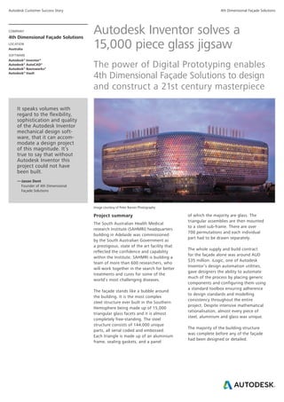
Autodesk Inventor solves a
15,000 piece glass jigsaw
The power of Digital Prototyping enables
4th Dimensional Façade Solutions to design
and construct a 21st century masterpiece
Image courtesy of Peter Barnes Photography
Project summary
The South Australian Health Medical
research Institute (SAHMRI) headquarters
building in Adelaide was commissioned
by the South Australian Government as
a prestigious, state of the art facility that
reflected the confidence and capability
within the Institute. SAHMRI is building a
team of more than 600 researchers, who
will work together in the search for better
treatments and cures for some of the
world’s most challenging diseases.
The façade stands like a bubble around
the building. It is the most complex
steel structure ever built in the Southern
Hemisphere being made up of 15,000
triangular glass facets and it is almost
completely free-standing. The steel
structure consists of 144,000 unique
parts, all serial coded and embossed.
Each triangle is made up of an aluminium
frame, sealing gaskets, and a panel
of which the majority are glass. The
triangular assemblies are then mounted
to a steel sub-frame. There are over
700 permutations and each individual
part had to be drawn separately.
The whole supply and build contract
for the façade alone was around AUD
$35 million. iLogic, one of Autodesk
Inventor’s design automation utilities,
gave designers the ability to automate
much of the process by placing generic
components and configuring them using
a standard toolbox ensuring adherence
to design standards and modelling
consistency throughout the entire
project. Despite intensive mathematical
rationalisation, almost every piece of
steel, aluminium and glass was unique.
The majority of the building structure
was complete before any of the façade
had been designed or detailed.
2. Autodesk Customer Success Story 4th Dimensional Façade Solutions
“The power of Inventor first came to our rescue in our
collaboration with the rest of the design team - we could review
any aspect of the design in 3D at any stage to show where the
mismatches were occurring. Inventor iLogic components meant
that infinite configurations of standard parts were placed with
total confidence and there were no variations based on the
operators personal modelling preferences,” says Dent.
The challenge
The architects had developed a 3D zero
thickness surface model of the inside of
the desired façade. The highest priority
and the biggest challenge was ordering
$10m of glass due to manufacturing
lead times, before anything else was
designed. Creating cutting details for the
glass was the first challenge, followed
by the details of the window frames and
then the supporting steel. The design of
the supporting steel between the glass
and the existing building was particularly
challenging as there was no possibility to
change either the glass (as it was
pre-ordered) or the supporting structure
as it was already there.
Curving triangular structures are typically
built using round hollow steel sections,
but this façade design called for
rectangular sections thereby dramatically
increasing the complexity of the steel
fabrication. Unlike a jigsaw where the
challenge is to guess where every part
goes, labelling over 250,000 components
was vital to ensuring no guessing was
necessary on the construction site.
The solution
All of the software vendors we spoke to
shrank from this challenge, says Dent.
“Autodesk Inventor had proven itself on
several previous projects, but no one had
tried anything this big, so we imported
the surface model and the project just
evolved from there.”
This evolution included a design team
with nearly 30 individuals involved
through 10 cities and 3 continents.
“Being able to “speak 3D” was the
only language that worked,” says Peter
Crawley, 3D Consultant from Autodesk
reseller CADPRO Systems Ltd. “If we
hadn’t used Inventor it would have meant
in excess of 200,000 2D drawings each
taking an average of 20 minutes for
each drawing.”
“In detailing the glass, we realised that
you can’t just thicken the surface model
because you get big gaps as the triangles
move round the outside of a curve,”
says Crawley. An intelligent iLogic part
was developed that looked at each triangle
and its angle to each of its neighbours,
which then sized the glass accordingly.
This “true shape” of all 15,000 triangles
was then used to ‘profile cut’ the glass.
“We decided to produce 2D drawings for
checking purposes. A special program
was developed inside Inventor that saved
thousands of hours of repetitive 2D
detailing work,” says Dent, who added
“It’s just a shame we couldn’t check them
as quickly!”
After managing to get the glass ordered,
the window frames needed building.
Image courtesy of 4th Dimensional Façade Solutions
3. Autodesk Customer Success Story 4th Dimensional Façade Solutions
The size of every triangle was
automatically extracted to a spreadsheet,
which fed a new Inventor iLogic window
frame assembly.
“We didn’t model every frame, there
was no point,” says Crawley. “We just
created a few hundred for clash detection
with the steel.” Autodesk Inventor
was particularly useful when it came
to analysing how the various glazing
components came together at a junction
or a node point. The junction between the
glazing triangles is essentially a six sided
node like a hexagon. “A junction appears
to work when it’s illustrated on a 2D
drawing,” says Crawley. “But when you
have a look at it in three dimensions then
it suddenly doesn’t work any more.” It
wasn’t until people started to realise how
complicated the geometry could become,
especially as the façade goes round a
curve, that the whole engineering design
had to change. The steelwork junctions
were equally complex. It was decided that
the nodes should be simple hexagons that
varied in shape to accommodate different
steel section sizes.
One of the most difficult problems was
to find the normal to 6 (or 7) triangles
meeting at a single vertex or node, which
would be valid in both concave and
convex situations. This made the node
design uncertain and gave rise to nodes
that varied from a simple hexagon to
unique six sided nodes whose sides
varied in length depending on their
orientation. Inventor’s iLogic tool enabled
designers to place a generic node, then
configure it to suit the conditions.
“There were several occasions where
we just ran into roadblocks and we
couldn’t figure out how to get round
some of the problems,” says Crawley.
“And in most of the situations things
were resolved by people having last-
minute inspiration while they were taking
a shower or similar. Once one problem
was solved we just moved onto the
next one until everything was fixed.”
“Almost by accident we discovered a
repeatable technique to build complex
manufacturable assemblies against a
simple point cloud,” says Crawley.
“With this technique, any shape made
from triangular facets like this becomes
surprisingly quick and easy to build.
”One of the other features of Inventor,
which saved considerable time for the
designers, was the ability to emboss each
component. In any given model you had
maybe 20,000 components open, it took
a finite period of time to interrogate each
part by accessing its properties to identify
it. To avoid having to do this, 4DFS
embossed the part number and the grade
of the material on each part.
When the designer was moving around
in 3D space, he could interrogate the part
by simply inspecting the embossing.
“It’s like engraving the part number and
the material specification into the part,”
says Dent. The embossing was kept
on the part and it was a considerable
aid to the construction process in the
workshops in China. This also enabled
any 3rd party review process (like DWF™
and Navisworks) to work without any
additional data being provided.
“The generic iLogic steel component
was also designed to change colour if
you changed the section size or grade
of steel which made downstream
inspection (in say Navisworks or DWF) so
much easier,” says Crawley. “On many
occasions, new design criteria or steel
sizes were added, and iLogic was able to
update every single part already made.”
“There are some new Autodesk tools like
BIM 360™
Glue and Mockup 360™
that
would have saved us weeks of time
collaborating with stakeholders around
the globe, but at the time we just made
Image courtesy of 4th Dimensional Façade Solutions