SlideShare a Scribd company logo
1 of 9
Download to read offline
Robust Laser Interferometer (RLI) – A New Tool for Condition Monitoring of Rotating Machines
1
Introduction:
Corporations and government agencies that own and/or operate large, critical machines are increasingly
implementing Condition Based Maintenance (CBM) or Reliability Centered Maintenance (RCM)
programs to optimize productivity and minimize life cycle costs associated with these expensive assets.
One of the pillars of any successful CBM or RCM program is a robust condition monitoring (CM) program
that provides accurate, real-time information regarding the health status of critical machine
components such as bearings and gears.
While a number of condition monitoring (CM) tools are available to maintenance professionals, they
often fail to detect problems much before catastrophic failure occurs, or they are cumbersome and
expensive to operate. In many cases, mechanical degradation is not detected until a substantial amount
of damage has occurred to the bearing or gear.
LaserSense, Inc. is preparing to introduce a unique, proprietary tool for condition monitoring (CM) of
critical machine components such as bearings and gears. This device will provide maintenance
professionals with a powerful new capability for accurately diagnosing machine problems, earlier than is
possible with other CM tools. The RLI (Robust Laser Interferometer) is versatile and robust, and it offers
the dual capability of vibration analysis and acoustic emission (AE) monitoring. This is important
because several studies have demonstrated that AE testing provides earlier and more accurate
detection of bearing and gear problems than is possible with vibration analysis (reference 1). It is also
anticipated that the AE measurement capability provided by the RLI will enable CM and NDE
professionals to more fully exploit the capabilities of AE monitoring, in the “real world”.
What does this mean for owners and operators of critical machines? The ultimate outcome will be a
tool that enables machine maintenance professionals to substantially improve productivity and reduce
maintenance costs for the assets that that they operate and maintain. More specifically, the RLI will
enable machine operations and maintenance (O&M) professionals to improve their condition
monitoring initiatives in the following ways:
 Provide earlier detection of bearing and gear problems, such as pitting, rolling contact fatigue,
abrasive wear etc.
 Provide more accurate and comprehensive and complete information regarding the health
status of critical machine components
 Improve the ability to detect and characterize lubrication problems, such as water
contamination, viscosity breakdown etc.
 Minimize set-up and operating costs associated with the set-up and operation of machine
condition monitoring programs
 Substantially reduce the need for 'a priori' information and minimize the need to select the
correct sensor (compared to systems based on accelerometers or piezoelectric sensors)
Robust Laser Interferometer (RLI) – A New Tool for Condition Monitoring of Rotating Machines
2
Figure 1.0
 Enable oil analysis professionals to more effectively and efficiently select the best tests and
programs for a specific application
Ultimately, the RLI will become a condition monitoring tool that greatly improves the performance and
cost effectiveness of diagnostic and prognostic programs for rotating machines in a way that is just not
possible with existing technologies.
RLI – An Overview:
The Robust Laser Interferometer (RLI) measurement capability, developed under private IR&D funding,
provides large dynamic range (up to 180 dB demonstrated in both displacement and acceleration),
wideband (0 Hz to 1,000,000+ Hz) measurement of surface vibration information, in multiple data
formats including displacement, velocity and acceleration. This proprietary measurement capability can
be provided by either a portable point-and-shoot laser interferometer configuration (Reference 2) or a
fiber optic configuration (Reference 3) that allows for continuous monitoring of critical assets. The
system is based upon a laser, optics and computer technology, all technologies that have a history of
cost reduction in mature systems. As the system output is in digital format, the RLI measurement
capability is amenable to automation and can be readily integrated into other condition based
maintenance (CBM) systems.
Figure 1.0 illustrates RLI’s
displacement measurement
noise floor. The RLI
displacement noise floor (1
Hertz measurement bin widths)
is about an order of magnitude
below one-millionth of one-
millionth of a meter (10-12 meter).
It should be noted that 10-12
meters is two orders of
magnitude smaller than an
angstrom, or alternatively, three
or four orders of magnitude
smaller than a nanotube
diameter or the width of a DNA
molecule. The noise floor
shown in Figure 1.0 is due to
“electronic noise”.
The 1.0 Hertz frequency bin widths provide
for an easy and consistent ability to compare
different measurements. But it should be noted that individual frequency measurements can be further
resolved (as a function of signal-to-noise ratio) down to small fractions of a Hertz (e.g., 0.01 Hertz). The
RLI has a spectrum resolution capability down to 1/64 Hertz bin widths.
Robust Laser Interferometer (RLI) – A New Tool for Condition Monitoring of Rotating Machines
3
RLI – A New Tool for Condition Monitoring of Critical Machines and Infrastructure:
There are at least two conceptually different ways to use vibration information for monitoring the
health of critical rotating machines. One involves monitoring of ‘design characteristics’ (and changes
thereto) for the machine or structure as a whole, while the second involves monitoring the failure
progression as physical damage progresses for an individual part or piece or component. When a
machine is designed and manufactured, it has certain characteristics (e.g., think of the resonance of a
simple tuning fork). The sum of all the physical make-up of the critical machine components yields a
vibration design signature for the machine as a healthy unit. Changes in the vibration signature
characteristics can be monitored as parts and components wear and conditions change.
At the same time, there are substantial benefits to being able to monitor individual machine
components. After an initial run-in or break-in period, all machine parts and components theoretically
start out life as “healthy” parts. Of course, healthy is a relative term, since not all parts are created
equal. From the initial machine start-up, the machine may only be as good as its least healthy part. Parts
can begin their life with defects at the molecular level. In addition, inadequate maintenance or improper
operation can quickly degrade even healthy machine parts. In any case, the machine parts and
components are exposed to a variety of stresses (i.e. tensile, compressive, bending, shear torsion). In
response to these stresses, the part experiences “strain”, which leads to a change in shape of the
internal molecular structure. If this strain results in elastic deformation, then the material returns to its
original shape. Of more concern are the plastic deformations that result in a permanent shape change
and permanent physical damage.
Examples of plastic deformation that are a real concern for CBM professionals are cracks and tears of
the material comprising the part or component in question. All cracks and tears generate Acoustic
Emissions (AE). More specifically, the AE is generated by the dislocation of material within the part, and
it has a point of physical origin, such as when a crack forms or grows. These events manifest their
presence in the form of high frequency vibrations. So as machine components degrade, the RLI provides
a unique, dual capability - it measures both the machine’s vibration design signature and the AE
distribution simultaneously.
RLI versus Accelerometer and Piezoelectric Systems:
Condition monitoring systems that rely on accelerometers attempt to generate an accurate picture of
machinery health by observing changes to the vibration design signature. Because accelerometers have
limited bandwidth, they measure just a portion of the vibration design signature. They cannot access the
information provided, for example, in higher order harmonics and they cannot measure very low
frequencies well. Actually, accelerometers have no measurement capability below a certain frequency.
The measurement capability of commercially available AE contact sensors was compared with the RLI
measurement capability in a laboratory environment. A rotorcraft gearbox simulator was used to
compare RLI measurements with those obtained from a piezoelectric AE sensor, where the RLI was
pointed at the case of the AE sensor, that was in turn attached to a “shaker” output (i.e. physical
simulation output – details are available). Figure 2.0 provides brief information regarding comparison of
RLI measurements with those outlined from a quality accelerometer system. At low frequencies, RLI can
provide measurement information not available from the contact accelerometer system. As an example,
the data on the right side of Figure 2.0 illustrates that, in side-by-side measurements in a rotorcraft
Robust Laser Interferometer (RLI) – A New Tool for Condition Monitoring of Rotating Machines
4
gearbox test cell, the accelerometer was incapable of identifying the first 10 (approximately) harmonics
of the main rotor rotational speed. (Reference 2). With both systems measuring the same physical
events, the RLI always faithfully recorded the harmonic or combination of harmonics selected for the
simulation.
In every case investigated, the spectrum output reported by the piezoelectric AE contact system was
complex and not singularly informative.
Additionally, RLI measurements have indicated that the spectrum area where commercial AE contact
sensors collect data often contains both higher order harmonics associated with the design frequencies
as well as AE. Figure 3.0 provides data for a turbine engine example where harmonics go into the
hundreds of kilohertz.
RLI provides correct measurement of the vibration design signature that is sought by accelerometer
systems. This includes measurement of potentially important very low and very high frequency
components that are simply not within the measurement range of even the very best and most
expensive accelerometers. But unlike accelerometer-based systems, RLI provides a measurement
capability for the acoustic emissions (AE) health signature, enabling direct and accurate monitoring of
the physical health of individual machine parts and pieces and components, from the first day of a
machine’s operation. Accelerometer-based vibration measurement systems cannot provide very early
indication of the type of mechanical or physical damage that leads to premature machine downtime. In
Figure 2.0
Robust Laser Interferometer (RLI) – A New Tool for Condition Monitoring of Rotating Machines
5
most cases, at the point where the accelerometer system sees damage, the damage has progressed to
such an extent that, at best, the system can provide a warning of impending failure.
Ultimately, RLI provides the reliability professional with a range of choices and capabilities that enable
them to more accurately monitor machine health over its entire life cycle.
A Brief History of RLI:
The RLI measurement capability was
initially developed to support tactical
sensing requirements (please note –
more information is available for those
interested in pursuing those
applications). The RLI was first used for
machine condition monitoring in
support of Nuclear Regulatory
Commission (NRC) interest in comparing
non-contact RLI measurement capability
with contact accelerometer
measurement capability. The RLI was
also used in a non-destructive testing
(NDT) role, in support of NASA “pre-fire
alertment” research. For the NRC effort,
the RLI measurement bandwidth was 0
Hertz to 524,288 Hertz. Extensive
measurement experience has
demonstrated that meaningful
information exists across a very broad
bandwidth. The ability to measure the
very lowest frequencies AND much
higher frequencies associated with
acoustic emission (AE) events, with the
very same device, is a unique and
powerful capability possessed by RLI.
How Can RLI Contribute to a Condition
Based Maintenance (CBM) Program?
To maximize the value of a CBM program, it is important to use condition monitoring tools and
techniques that provide accurate, detailed information regarding the condition of critical machines, and
more specifically, the individual parts and pieces of that machine. It is important, for example, to have
an accurate picture of the mechanical health of a machine’s bearings and gears, at all stages of the
machine’s life cycle.
CBM personnel use condition monitoring tools to detect, for example, bearings that are about to fail or
that are wearing prematurely or that may be operating with contaminated, degraded lubricant. If the
Figure 3.0
Robust Laser Interferometer (RLI) – A New Tool for Condition Monitoring of Rotating Machines
6
bearing damage is detected just before it fails, then at least catastrophic secondary damage and
downtime can be prevented. Ultimately, though, the value of a CBM program is optimized when
maintenance professionals can detect abnormal or premature wear well in advance of a pending failure.
Maintenance personnel armed with this information can optimize the value of their CBM program as
follows:
• Address the root cause of the wear and prevent further degradation of the component in question.
This saves money by reducing expenditures for components such as bearings, gears and valves.
• Facilitate maintenance planning: enable better allocation of maintenance labor assets
• Prevent unscheduled downtime: this saves money by reducing the reliance on expensive rental
equipment by reducing the need for redundant systems
• Prevent accidents and injuries that result from unscheduled, catastrophic failures
Legacy systems such as those based on accelerometers are typically incapable of reliably identifying
“incipient” or very early stage failure. These incipient events occur at the molecular level. It has been
our experience that, for a variety of reasons, incipient events are best isolated by processing the
vibration information available at very high Acoustic Emission (AE) frequencies. The ability of RLI to
identify incipient degradation has been documented in several applications. Examples are presented in
Figures 4.0 and 5.0 respectively. Figure 4.0 is from a bearing and Figure 5.0 is from the “pre-fire”
monitoring mentioned previously. Figure 4.0 bandpass is from 440,000 Hertz to 524,288 Hertz while
Figure 5.0 bandpass is from 425,000 Hertz to 524,288 Hertz.
The “pre-fire” experiments referenced above clearly demonstrated the presence of AE well before any
other damage (ie charring, smoking) was evident.
Figure 4.0
Bearing AE Events (Processing High Pass Filter, Pass Freq. 440,000 Hz)
Robust Laser Interferometer (RLI) – A New Tool for Condition Monitoring of Rotating Machines
7
While AE monitoring has been used for many years, for various NDE applications, it is not commonly
used as a CM tool for rotating machines. In a study that compared the diagnostic and prognostic
capabilities of Acoustic Emissions Testing (AET), vibration and oil analysis, Mba et. al. concluded that
“the AE technique was more sensitive in detecting and monitoring pitting than either the vibration or
Spectrometric Oil Analysis (SOA) techniques. It is concluded that as AE exhibited a direct relationship
with pitting progression, it offers the opportunity for prognosis.” The point here is that the Acoustic
Emissions Testing (AET) can be used to detect and measure the type of mechanical degradation that
leads to the failure of machine parts and components earlier than is possible with other CBM
techniques.
AE Testing as a Tool for Lubricant Film Condition and Performance:
Another potential application of AE testing that is of great interest for bearing health monitoring is real-
time monitoring of lubricant performance. It is known, for example, that events such as metal-on-metal
friction, cavitation or hard particle impacts generate AE. Unfortunately, existing AE measurement tools
typically lack the sensitivity to accurately identify the sometimes heavily modulated AE signals, or they
are overwhelmed by the background noise that is typical of industrial settings. It is suggested that the
RLI, with its substantially higher level of sensitivity, can provide the type of performance that is
necessary for real-time identification of bearing lubricant degradation. As lubricant quality degrades due
to internally or externally generated contaminants, the level of bearing stress would be expected to
increase. A seeded fault test conducted by the US Navy, for the Joint Strike Fighter program,
demonstrated the efficacy of RLI for identifying lubricant degradation issues. An example of this
concept is presented in Reference 2.
Figure 5.0
Pre-Fire Similar Events (Bandpass Filter from 425,000 to 524,000 Hz
Robust Laser Interferometer (RLI) – A New Tool for Condition Monitoring of Rotating Machines
8
Figure 6.0 describes, in terms of AE features, what is occurring to the bearing as it proceeds through 30
hours of “seeded fault” testing, illustrating character as a function of stress for an aviation turbine
system. The top left figure illustrates that there is a considerable amount of AE generated while the
inner race seeded fault is relatively fresh and “new”. There are probably metal fragments from the fault
together with metal on metal contact at the fault creating the AE. The resulting AE features related to
the forces acting on the bearing are impressive. The middle figure is an AE picture of the #1 bearing after
the inner race seeded fault has had a chance to “wear down/out” and the oil filters have removed some
of the larger particles (30 micron oil filter). The engine has been running over 17 hours, and is in the
middle of the “Oil Degradation Bearing Distress Programs.” However, the AE features shown in the top
left figure are approximately 10 times larger than those shown in the middle figure (vertical scales are
different). The bottom figure is essentially the AE baseline for the #1 bearing. The Oil Degradation /
Bearing Distress Programs are over. The oil has been changed and the oil is filtered down to 10 microns.
Almost all of the AE features in earlier figures are gone and those features that are left are at a very low
level. For example, the 38 fs1 group in the top figure is over 200 times larger than the 38 fs1 group of the
bottom figure. [It is important to recognize that the sequence shown in Figure 6.0 represents the
Robust Laser Interferometer (RLI) – A New Tool for Condition Monitoring of Rotating Machines
9
‘polishing away’ of a seeded fault, and that the sequence for degradation of a ‘good bearing’ would be in
the reverse order].
Conclusion:
The ultimate purpose of any machine condition monitoring program is to enable maintenance
professionals to accurately detect and diagnose critical machine component problems, including those
that are poised to result in premature, unplanned failure. Whether it’s an amusement park ride or a
compressor in a chemical plant or a gearbox on a cruise ship, the consequences of an unexpected failure
can be costly and possibly catastrophic in terms of human injuries or death. The RLI is poised to provide
a level of performance and cost effectiveness that is not currently possible with other condition
monitoring tools. It will provide earlier detection of bearing and gear wear than is possible with other
condition monitoring tools.
References:
(1) A comparative experimental study on the diagnostic and prognostic capabilities of Acoustic
Emissions, Vibration and Spectrometric Oil Analysis for spur gears; School of Industrial and
Manufacturing Science, School of Engineering, Cranfield University, Bedfordshire MK43 0AL, UK
(2) “Acoustic Emissions in Broadband Vibration as an indicator of Bearing Stress”, by T. Goodenow,
W. Hardman and M. Karchnak; 2000 IEEE Aerospace Conference, March 19-25, 2000, Big Sky,
Montana.
(3) “Wideband Fiber-Optic Vibration Measurement System Prototype Evaluation”, by T. Goodenow,
W. Hardman and M. Karchnak; 2001 IEEE Aerospace Conference, March 10-17, 2001, Big Sky,
Montana.
Contact Information:
John Zarroli
E-mail: John.Zarroli@LaserSenseInc.com
Phone: (301) 525-4467
www.LaserSenseInc.com

More Related Content

Similar to RLI - A New Tool for Condition Monitoring_121815

Vibration Analysis Guide.pdf
Vibration Analysis Guide.pdfVibration Analysis Guide.pdf
Vibration Analysis Guide.pdfPratap Kota
 
Assessment of Gearbox Fault DetectionUsing Vibration Signal Analysis and Acou...
Assessment of Gearbox Fault DetectionUsing Vibration Signal Analysis and Acou...Assessment of Gearbox Fault DetectionUsing Vibration Signal Analysis and Acou...
Assessment of Gearbox Fault DetectionUsing Vibration Signal Analysis and Acou...IOSR Journals
 
Continuum Robots and Tactile Sensors
Continuum Robots and Tactile SensorsContinuum Robots and Tactile Sensors
Continuum Robots and Tactile SensorsTacuna Systems
 
Robotic Tactile Sensor Probe used for Contour plotting of Weld Joint in Seam ...
Robotic Tactile Sensor Probe used for Contour plotting of Weld Joint in Seam ...Robotic Tactile Sensor Probe used for Contour plotting of Weld Joint in Seam ...
Robotic Tactile Sensor Probe used for Contour plotting of Weld Joint in Seam ...IRJET Journal
 
vibration analysis companies
vibration analysis companiesvibration analysis companies
vibration analysis companiesRMSC
 
vibration analysis companies
vibration analysis companiesvibration analysis companies
vibration analysis companiesRMSC
 
DESIGN AND DEVELOPMENT OF MACHINE FAULT SIMULATOR (MFS) FOR FAULT DIAGNOSIS
DESIGN AND DEVELOPMENT OF MACHINE FAULT SIMULATOR (MFS) FOR FAULT DIAGNOSISDESIGN AND DEVELOPMENT OF MACHINE FAULT SIMULATOR (MFS) FOR FAULT DIAGNOSIS
DESIGN AND DEVELOPMENT OF MACHINE FAULT SIMULATOR (MFS) FOR FAULT DIAGNOSISijmech
 
Chapter 2 Sensors_3rd Edition_Feb2017.pdf
Chapter 2 Sensors_3rd Edition_Feb2017.pdfChapter 2 Sensors_3rd Edition_Feb2017.pdf
Chapter 2 Sensors_3rd Edition_Feb2017.pdfaiateam
 
A new wavelet feature for fault diagnosis
A new wavelet feature for fault diagnosisA new wavelet feature for fault diagnosis
A new wavelet feature for fault diagnosisIAEME Publication
 
Redeeming of processor for cyber physical systems
Redeeming of processor for cyber physical systemsRedeeming of processor for cyber physical systems
Redeeming of processor for cyber physical systemseSAT Publishing House
 
Design Auto Adjust Sliding Surface Slope: Applied to Robot Manipulator
Design Auto Adjust Sliding Surface Slope: Applied to Robot ManipulatorDesign Auto Adjust Sliding Surface Slope: Applied to Robot Manipulator
Design Auto Adjust Sliding Surface Slope: Applied to Robot ManipulatorWaqas Tariq
 
Camera Encoded Phased Array for Semi-Automated Inspection of Complex Composit...
Camera Encoded Phased Array for Semi-Automated Inspection of Complex Composit...Camera Encoded Phased Array for Semi-Automated Inspection of Complex Composit...
Camera Encoded Phased Array for Semi-Automated Inspection of Complex Composit...Innerspec Technologies
 
IRJET- Influence of Noise and Testing Vibration to Comfort in Diesel Engi...
IRJET-  	  Influence of Noise and Testing Vibration to Comfort in Diesel Engi...IRJET-  	  Influence of Noise and Testing Vibration to Comfort in Diesel Engi...
IRJET- Influence of Noise and Testing Vibration to Comfort in Diesel Engi...IRJET Journal
 
Modeling and Control of a Spherical Rolling Robot Using Model Reference Adapt...
Modeling and Control of a Spherical Rolling Robot Using Model Reference Adapt...Modeling and Control of a Spherical Rolling Robot Using Model Reference Adapt...
Modeling and Control of a Spherical Rolling Robot Using Model Reference Adapt...IRJET Journal
 
MET 105 Non destructive tests-module(new)
MET 105 Non destructive tests-module(new)MET 105 Non destructive tests-module(new)
MET 105 Non destructive tests-module(new)Ibrahim AboKhalil
 
Adaptive MIMO Fuzzy Compensate Fuzzy Sliding Mode Algorithm: Applied to Secon...
Adaptive MIMO Fuzzy Compensate Fuzzy Sliding Mode Algorithm: Applied to Secon...Adaptive MIMO Fuzzy Compensate Fuzzy Sliding Mode Algorithm: Applied to Secon...
Adaptive MIMO Fuzzy Compensate Fuzzy Sliding Mode Algorithm: Applied to Secon...CSCJournals
 
Analysis and control of mobile robot for pipe line inspection 2
Analysis and control of mobile robot for pipe line inspection 2Analysis and control of mobile robot for pipe line inspection 2
Analysis and control of mobile robot for pipe line inspection 2IAEME Publication
 

Similar to RLI - A New Tool for Condition Monitoring_121815 (20)

Vibration Analysis Guide.pdf
Vibration Analysis Guide.pdfVibration Analysis Guide.pdf
Vibration Analysis Guide.pdf
 
Assessment of Gearbox Fault DetectionUsing Vibration Signal Analysis and Acou...
Assessment of Gearbox Fault DetectionUsing Vibration Signal Analysis and Acou...Assessment of Gearbox Fault DetectionUsing Vibration Signal Analysis and Acou...
Assessment of Gearbox Fault DetectionUsing Vibration Signal Analysis and Acou...
 
Continuum Robots and Tactile Sensors
Continuum Robots and Tactile SensorsContinuum Robots and Tactile Sensors
Continuum Robots and Tactile Sensors
 
Dana Lee Church - R15.3
Dana Lee Church - R15.3Dana Lee Church - R15.3
Dana Lee Church - R15.3
 
Robotic Tactile Sensor Probe used for Contour plotting of Weld Joint in Seam ...
Robotic Tactile Sensor Probe used for Contour plotting of Weld Joint in Seam ...Robotic Tactile Sensor Probe used for Contour plotting of Weld Joint in Seam ...
Robotic Tactile Sensor Probe used for Contour plotting of Weld Joint in Seam ...
 
vibration analysis companies
vibration analysis companiesvibration analysis companies
vibration analysis companies
 
vibration analysis companies
vibration analysis companiesvibration analysis companies
vibration analysis companies
 
Vibration monitoring
Vibration monitoringVibration monitoring
Vibration monitoring
 
DESIGN AND DEVELOPMENT OF MACHINE FAULT SIMULATOR (MFS) FOR FAULT DIAGNOSIS
DESIGN AND DEVELOPMENT OF MACHINE FAULT SIMULATOR (MFS) FOR FAULT DIAGNOSISDESIGN AND DEVELOPMENT OF MACHINE FAULT SIMULATOR (MFS) FOR FAULT DIAGNOSIS
DESIGN AND DEVELOPMENT OF MACHINE FAULT SIMULATOR (MFS) FOR FAULT DIAGNOSIS
 
Chapter 2 Sensors_3rd Edition_Feb2017.pdf
Chapter 2 Sensors_3rd Edition_Feb2017.pdfChapter 2 Sensors_3rd Edition_Feb2017.pdf
Chapter 2 Sensors_3rd Edition_Feb2017.pdf
 
A new wavelet feature for fault diagnosis
A new wavelet feature for fault diagnosisA new wavelet feature for fault diagnosis
A new wavelet feature for fault diagnosis
 
Redeeming of processor for cyber physical systems
Redeeming of processor for cyber physical systemsRedeeming of processor for cyber physical systems
Redeeming of processor for cyber physical systems
 
Design Auto Adjust Sliding Surface Slope: Applied to Robot Manipulator
Design Auto Adjust Sliding Surface Slope: Applied to Robot ManipulatorDesign Auto Adjust Sliding Surface Slope: Applied to Robot Manipulator
Design Auto Adjust Sliding Surface Slope: Applied to Robot Manipulator
 
Camera Encoded Phased Array for Semi-Automated Inspection of Complex Composit...
Camera Encoded Phased Array for Semi-Automated Inspection of Complex Composit...Camera Encoded Phased Array for Semi-Automated Inspection of Complex Composit...
Camera Encoded Phased Array for Semi-Automated Inspection of Complex Composit...
 
IRJET- Influence of Noise and Testing Vibration to Comfort in Diesel Engi...
IRJET-  	  Influence of Noise and Testing Vibration to Comfort in Diesel Engi...IRJET-  	  Influence of Noise and Testing Vibration to Comfort in Diesel Engi...
IRJET- Influence of Noise and Testing Vibration to Comfort in Diesel Engi...
 
Modeling and Control of a Spherical Rolling Robot Using Model Reference Adapt...
Modeling and Control of a Spherical Rolling Robot Using Model Reference Adapt...Modeling and Control of a Spherical Rolling Robot Using Model Reference Adapt...
Modeling and Control of a Spherical Rolling Robot Using Model Reference Adapt...
 
MET 105 Non destructive tests-module(new)
MET 105 Non destructive tests-module(new)MET 105 Non destructive tests-module(new)
MET 105 Non destructive tests-module(new)
 
201421402011.pptx
201421402011.pptx201421402011.pptx
201421402011.pptx
 
Adaptive MIMO Fuzzy Compensate Fuzzy Sliding Mode Algorithm: Applied to Secon...
Adaptive MIMO Fuzzy Compensate Fuzzy Sliding Mode Algorithm: Applied to Secon...Adaptive MIMO Fuzzy Compensate Fuzzy Sliding Mode Algorithm: Applied to Secon...
Adaptive MIMO Fuzzy Compensate Fuzzy Sliding Mode Algorithm: Applied to Secon...
 
Analysis and control of mobile robot for pipe line inspection 2
Analysis and control of mobile robot for pipe line inspection 2Analysis and control of mobile robot for pipe line inspection 2
Analysis and control of mobile robot for pipe line inspection 2
 

RLI - A New Tool for Condition Monitoring_121815

  • 1. Robust Laser Interferometer (RLI) – A New Tool for Condition Monitoring of Rotating Machines 1 Introduction: Corporations and government agencies that own and/or operate large, critical machines are increasingly implementing Condition Based Maintenance (CBM) or Reliability Centered Maintenance (RCM) programs to optimize productivity and minimize life cycle costs associated with these expensive assets. One of the pillars of any successful CBM or RCM program is a robust condition monitoring (CM) program that provides accurate, real-time information regarding the health status of critical machine components such as bearings and gears. While a number of condition monitoring (CM) tools are available to maintenance professionals, they often fail to detect problems much before catastrophic failure occurs, or they are cumbersome and expensive to operate. In many cases, mechanical degradation is not detected until a substantial amount of damage has occurred to the bearing or gear. LaserSense, Inc. is preparing to introduce a unique, proprietary tool for condition monitoring (CM) of critical machine components such as bearings and gears. This device will provide maintenance professionals with a powerful new capability for accurately diagnosing machine problems, earlier than is possible with other CM tools. The RLI (Robust Laser Interferometer) is versatile and robust, and it offers the dual capability of vibration analysis and acoustic emission (AE) monitoring. This is important because several studies have demonstrated that AE testing provides earlier and more accurate detection of bearing and gear problems than is possible with vibration analysis (reference 1). It is also anticipated that the AE measurement capability provided by the RLI will enable CM and NDE professionals to more fully exploit the capabilities of AE monitoring, in the “real world”. What does this mean for owners and operators of critical machines? The ultimate outcome will be a tool that enables machine maintenance professionals to substantially improve productivity and reduce maintenance costs for the assets that that they operate and maintain. More specifically, the RLI will enable machine operations and maintenance (O&M) professionals to improve their condition monitoring initiatives in the following ways:  Provide earlier detection of bearing and gear problems, such as pitting, rolling contact fatigue, abrasive wear etc.  Provide more accurate and comprehensive and complete information regarding the health status of critical machine components  Improve the ability to detect and characterize lubrication problems, such as water contamination, viscosity breakdown etc.  Minimize set-up and operating costs associated with the set-up and operation of machine condition monitoring programs  Substantially reduce the need for 'a priori' information and minimize the need to select the correct sensor (compared to systems based on accelerometers or piezoelectric sensors)
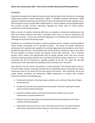
  • 2. Robust Laser Interferometer (RLI) – A New Tool for Condition Monitoring of Rotating Machines 2 Figure 1.0  Enable oil analysis professionals to more effectively and efficiently select the best tests and programs for a specific application Ultimately, the RLI will become a condition monitoring tool that greatly improves the performance and cost effectiveness of diagnostic and prognostic programs for rotating machines in a way that is just not possible with existing technologies. RLI – An Overview: The Robust Laser Interferometer (RLI) measurement capability, developed under private IR&D funding, provides large dynamic range (up to 180 dB demonstrated in both displacement and acceleration), wideband (0 Hz to 1,000,000+ Hz) measurement of surface vibration information, in multiple data formats including displacement, velocity and acceleration. This proprietary measurement capability can be provided by either a portable point-and-shoot laser interferometer configuration (Reference 2) or a fiber optic configuration (Reference 3) that allows for continuous monitoring of critical assets. The system is based upon a laser, optics and computer technology, all technologies that have a history of cost reduction in mature systems. As the system output is in digital format, the RLI measurement capability is amenable to automation and can be readily integrated into other condition based maintenance (CBM) systems. Figure 1.0 illustrates RLI’s displacement measurement noise floor. The RLI displacement noise floor (1 Hertz measurement bin widths) is about an order of magnitude below one-millionth of one- millionth of a meter (10-12 meter). It should be noted that 10-12 meters is two orders of magnitude smaller than an angstrom, or alternatively, three or four orders of magnitude smaller than a nanotube diameter or the width of a DNA molecule. The noise floor shown in Figure 1.0 is due to “electronic noise”. The 1.0 Hertz frequency bin widths provide for an easy and consistent ability to compare different measurements. But it should be noted that individual frequency measurements can be further resolved (as a function of signal-to-noise ratio) down to small fractions of a Hertz (e.g., 0.01 Hertz). The RLI has a spectrum resolution capability down to 1/64 Hertz bin widths.
  • 3. Robust Laser Interferometer (RLI) – A New Tool for Condition Monitoring of Rotating Machines 3 RLI – A New Tool for Condition Monitoring of Critical Machines and Infrastructure: There are at least two conceptually different ways to use vibration information for monitoring the health of critical rotating machines. One involves monitoring of ‘design characteristics’ (and changes thereto) for the machine or structure as a whole, while the second involves monitoring the failure progression as physical damage progresses for an individual part or piece or component. When a machine is designed and manufactured, it has certain characteristics (e.g., think of the resonance of a simple tuning fork). The sum of all the physical make-up of the critical machine components yields a vibration design signature for the machine as a healthy unit. Changes in the vibration signature characteristics can be monitored as parts and components wear and conditions change. At the same time, there are substantial benefits to being able to monitor individual machine components. After an initial run-in or break-in period, all machine parts and components theoretically start out life as “healthy” parts. Of course, healthy is a relative term, since not all parts are created equal. From the initial machine start-up, the machine may only be as good as its least healthy part. Parts can begin their life with defects at the molecular level. In addition, inadequate maintenance or improper operation can quickly degrade even healthy machine parts. In any case, the machine parts and components are exposed to a variety of stresses (i.e. tensile, compressive, bending, shear torsion). In response to these stresses, the part experiences “strain”, which leads to a change in shape of the internal molecular structure. If this strain results in elastic deformation, then the material returns to its original shape. Of more concern are the plastic deformations that result in a permanent shape change and permanent physical damage. Examples of plastic deformation that are a real concern for CBM professionals are cracks and tears of the material comprising the part or component in question. All cracks and tears generate Acoustic Emissions (AE). More specifically, the AE is generated by the dislocation of material within the part, and it has a point of physical origin, such as when a crack forms or grows. These events manifest their presence in the form of high frequency vibrations. So as machine components degrade, the RLI provides a unique, dual capability - it measures both the machine’s vibration design signature and the AE distribution simultaneously. RLI versus Accelerometer and Piezoelectric Systems: Condition monitoring systems that rely on accelerometers attempt to generate an accurate picture of machinery health by observing changes to the vibration design signature. Because accelerometers have limited bandwidth, they measure just a portion of the vibration design signature. They cannot access the information provided, for example, in higher order harmonics and they cannot measure very low frequencies well. Actually, accelerometers have no measurement capability below a certain frequency. The measurement capability of commercially available AE contact sensors was compared with the RLI measurement capability in a laboratory environment. A rotorcraft gearbox simulator was used to compare RLI measurements with those obtained from a piezoelectric AE sensor, where the RLI was pointed at the case of the AE sensor, that was in turn attached to a “shaker” output (i.e. physical simulation output – details are available). Figure 2.0 provides brief information regarding comparison of RLI measurements with those outlined from a quality accelerometer system. At low frequencies, RLI can provide measurement information not available from the contact accelerometer system. As an example, the data on the right side of Figure 2.0 illustrates that, in side-by-side measurements in a rotorcraft
  • 4. Robust Laser Interferometer (RLI) – A New Tool for Condition Monitoring of Rotating Machines 4 gearbox test cell, the accelerometer was incapable of identifying the first 10 (approximately) harmonics of the main rotor rotational speed. (Reference 2). With both systems measuring the same physical events, the RLI always faithfully recorded the harmonic or combination of harmonics selected for the simulation. In every case investigated, the spectrum output reported by the piezoelectric AE contact system was complex and not singularly informative. Additionally, RLI measurements have indicated that the spectrum area where commercial AE contact sensors collect data often contains both higher order harmonics associated with the design frequencies as well as AE. Figure 3.0 provides data for a turbine engine example where harmonics go into the hundreds of kilohertz. RLI provides correct measurement of the vibration design signature that is sought by accelerometer systems. This includes measurement of potentially important very low and very high frequency components that are simply not within the measurement range of even the very best and most expensive accelerometers. But unlike accelerometer-based systems, RLI provides a measurement capability for the acoustic emissions (AE) health signature, enabling direct and accurate monitoring of the physical health of individual machine parts and pieces and components, from the first day of a machine’s operation. Accelerometer-based vibration measurement systems cannot provide very early indication of the type of mechanical or physical damage that leads to premature machine downtime. In Figure 2.0
  • 5. Robust Laser Interferometer (RLI) – A New Tool for Condition Monitoring of Rotating Machines 5 most cases, at the point where the accelerometer system sees damage, the damage has progressed to such an extent that, at best, the system can provide a warning of impending failure. Ultimately, RLI provides the reliability professional with a range of choices and capabilities that enable them to more accurately monitor machine health over its entire life cycle. A Brief History of RLI: The RLI measurement capability was initially developed to support tactical sensing requirements (please note – more information is available for those interested in pursuing those applications). The RLI was first used for machine condition monitoring in support of Nuclear Regulatory Commission (NRC) interest in comparing non-contact RLI measurement capability with contact accelerometer measurement capability. The RLI was also used in a non-destructive testing (NDT) role, in support of NASA “pre-fire alertment” research. For the NRC effort, the RLI measurement bandwidth was 0 Hertz to 524,288 Hertz. Extensive measurement experience has demonstrated that meaningful information exists across a very broad bandwidth. The ability to measure the very lowest frequencies AND much higher frequencies associated with acoustic emission (AE) events, with the very same device, is a unique and powerful capability possessed by RLI. How Can RLI Contribute to a Condition Based Maintenance (CBM) Program? To maximize the value of a CBM program, it is important to use condition monitoring tools and techniques that provide accurate, detailed information regarding the condition of critical machines, and more specifically, the individual parts and pieces of that machine. It is important, for example, to have an accurate picture of the mechanical health of a machine’s bearings and gears, at all stages of the machine’s life cycle. CBM personnel use condition monitoring tools to detect, for example, bearings that are about to fail or that are wearing prematurely or that may be operating with contaminated, degraded lubricant. If the Figure 3.0
  • 6. Robust Laser Interferometer (RLI) – A New Tool for Condition Monitoring of Rotating Machines 6 bearing damage is detected just before it fails, then at least catastrophic secondary damage and downtime can be prevented. Ultimately, though, the value of a CBM program is optimized when maintenance professionals can detect abnormal or premature wear well in advance of a pending failure. Maintenance personnel armed with this information can optimize the value of their CBM program as follows: • Address the root cause of the wear and prevent further degradation of the component in question. This saves money by reducing expenditures for components such as bearings, gears and valves. • Facilitate maintenance planning: enable better allocation of maintenance labor assets • Prevent unscheduled downtime: this saves money by reducing the reliance on expensive rental equipment by reducing the need for redundant systems • Prevent accidents and injuries that result from unscheduled, catastrophic failures Legacy systems such as those based on accelerometers are typically incapable of reliably identifying “incipient” or very early stage failure. These incipient events occur at the molecular level. It has been our experience that, for a variety of reasons, incipient events are best isolated by processing the vibration information available at very high Acoustic Emission (AE) frequencies. The ability of RLI to identify incipient degradation has been documented in several applications. Examples are presented in Figures 4.0 and 5.0 respectively. Figure 4.0 is from a bearing and Figure 5.0 is from the “pre-fire” monitoring mentioned previously. Figure 4.0 bandpass is from 440,000 Hertz to 524,288 Hertz while Figure 5.0 bandpass is from 425,000 Hertz to 524,288 Hertz. The “pre-fire” experiments referenced above clearly demonstrated the presence of AE well before any other damage (ie charring, smoking) was evident. Figure 4.0 Bearing AE Events (Processing High Pass Filter, Pass Freq. 440,000 Hz)
  • 7. Robust Laser Interferometer (RLI) – A New Tool for Condition Monitoring of Rotating Machines 7 While AE monitoring has been used for many years, for various NDE applications, it is not commonly used as a CM tool for rotating machines. In a study that compared the diagnostic and prognostic capabilities of Acoustic Emissions Testing (AET), vibration and oil analysis, Mba et. al. concluded that “the AE technique was more sensitive in detecting and monitoring pitting than either the vibration or Spectrometric Oil Analysis (SOA) techniques. It is concluded that as AE exhibited a direct relationship with pitting progression, it offers the opportunity for prognosis.” The point here is that the Acoustic Emissions Testing (AET) can be used to detect and measure the type of mechanical degradation that leads to the failure of machine parts and components earlier than is possible with other CBM techniques. AE Testing as a Tool for Lubricant Film Condition and Performance: Another potential application of AE testing that is of great interest for bearing health monitoring is real- time monitoring of lubricant performance. It is known, for example, that events such as metal-on-metal friction, cavitation or hard particle impacts generate AE. Unfortunately, existing AE measurement tools typically lack the sensitivity to accurately identify the sometimes heavily modulated AE signals, or they are overwhelmed by the background noise that is typical of industrial settings. It is suggested that the RLI, with its substantially higher level of sensitivity, can provide the type of performance that is necessary for real-time identification of bearing lubricant degradation. As lubricant quality degrades due to internally or externally generated contaminants, the level of bearing stress would be expected to increase. A seeded fault test conducted by the US Navy, for the Joint Strike Fighter program, demonstrated the efficacy of RLI for identifying lubricant degradation issues. An example of this concept is presented in Reference 2. Figure 5.0 Pre-Fire Similar Events (Bandpass Filter from 425,000 to 524,000 Hz
  • 8. Robust Laser Interferometer (RLI) – A New Tool for Condition Monitoring of Rotating Machines 8 Figure 6.0 describes, in terms of AE features, what is occurring to the bearing as it proceeds through 30 hours of “seeded fault” testing, illustrating character as a function of stress for an aviation turbine system. The top left figure illustrates that there is a considerable amount of AE generated while the inner race seeded fault is relatively fresh and “new”. There are probably metal fragments from the fault together with metal on metal contact at the fault creating the AE. The resulting AE features related to the forces acting on the bearing are impressive. The middle figure is an AE picture of the #1 bearing after the inner race seeded fault has had a chance to “wear down/out” and the oil filters have removed some of the larger particles (30 micron oil filter). The engine has been running over 17 hours, and is in the middle of the “Oil Degradation Bearing Distress Programs.” However, the AE features shown in the top left figure are approximately 10 times larger than those shown in the middle figure (vertical scales are different). The bottom figure is essentially the AE baseline for the #1 bearing. The Oil Degradation / Bearing Distress Programs are over. The oil has been changed and the oil is filtered down to 10 microns. Almost all of the AE features in earlier figures are gone and those features that are left are at a very low level. For example, the 38 fs1 group in the top figure is over 200 times larger than the 38 fs1 group of the bottom figure. [It is important to recognize that the sequence shown in Figure 6.0 represents the
  • 9. Robust Laser Interferometer (RLI) – A New Tool for Condition Monitoring of Rotating Machines 9 ‘polishing away’ of a seeded fault, and that the sequence for degradation of a ‘good bearing’ would be in the reverse order]. Conclusion: The ultimate purpose of any machine condition monitoring program is to enable maintenance professionals to accurately detect and diagnose critical machine component problems, including those that are poised to result in premature, unplanned failure. Whether it’s an amusement park ride or a compressor in a chemical plant or a gearbox on a cruise ship, the consequences of an unexpected failure can be costly and possibly catastrophic in terms of human injuries or death. The RLI is poised to provide a level of performance and cost effectiveness that is not currently possible with other condition monitoring tools. It will provide earlier detection of bearing and gear wear than is possible with other condition monitoring tools. References: (1) A comparative experimental study on the diagnostic and prognostic capabilities of Acoustic Emissions, Vibration and Spectrometric Oil Analysis for spur gears; School of Industrial and Manufacturing Science, School of Engineering, Cranfield University, Bedfordshire MK43 0AL, UK (2) “Acoustic Emissions in Broadband Vibration as an indicator of Bearing Stress”, by T. Goodenow, W. Hardman and M. Karchnak; 2000 IEEE Aerospace Conference, March 19-25, 2000, Big Sky, Montana. (3) “Wideband Fiber-Optic Vibration Measurement System Prototype Evaluation”, by T. Goodenow, W. Hardman and M. Karchnak; 2001 IEEE Aerospace Conference, March 10-17, 2001, Big Sky, Montana. Contact Information: John Zarroli E-mail: John.Zarroli@LaserSenseInc.com Phone: (301) 525-4467 www.LaserSenseInc.com