Refinery Engineering Integrated Process Modeling And Optimization Aifu Chang
Refinery Engineering Integrated Process Modeling And Optimization Aifu Chang
Refinery Engineering Integrated Process Modeling And Optimization Aifu Chang
Refinery Engineering Integrated Process Modeling And Optimization Aifu Chang
Refinery Engineering Integrated Process Modeling And Optimization Aifu Chang
1.
Refinery Engineering IntegratedProcess Modeling
And Optimization Aifu Chang download
https://ebookbell.com/product/refinery-engineering-integrated-
process-modeling-and-optimization-aifu-chang-4057464
Explore and download more ebooks at ebookbell.com
2.
Here are somerecommended products that we believe you will be
interested in. You can click the link to download.
Fundamental Approaches To Software Engineering Reiner Hhnle Wil Van
Der Aalst
https://ebookbell.com/product/fundamental-approaches-to-software-
engineering-reiner-hhnle-wil-van-der-aalst-59042816
Performance Engineering State Of The Art And Current Trends 1st
Edition Reiner Dumke
https://ebookbell.com/product/performance-engineering-state-of-the-
art-and-current-trends-1st-edition-reiner-dumke-1143642
Fundamental Approaches To Software Engineering 22nd International
Conference Fase 2019 Held As Part Of The European Joint Conferences On
Theory And Practice Of Software Etaps 2019 Prague Czech Republic April
611 2019 Proceedings 1st Ed Reiner Hhnle
https://ebookbell.com/product/fundamental-approaches-to-software-
engineering-22nd-international-conference-fase-2019-held-as-part-of-
the-european-joint-conferences-on-theory-and-practice-of-software-
etaps-2019-prague-czech-republic-april-611-2019-proceedings-1st-ed-
reiner-hhnle-10487258
Refinery Feedstocks James G Speight
https://ebookbell.com/product/refinery-feedstocks-james-g-
speight-22130360
3.
The Refinery OfThe Future James G Speight
https://ebookbell.com/product/the-refinery-of-the-future-james-g-
speight-46793770
Algae Refinery Up And Downstream Processes 1st Edition Sanjeet
Mehariya
https://ebookbell.com/product/algae-refinery-up-and-downstream-
processes-1st-edition-sanjeet-mehariya-54052112
Handbook Of Refinery Desulfurization Nour Shafik Elgendy James G
Speight
https://ebookbell.com/product/handbook-of-refinery-desulfurization-
nour-shafik-elgendy-james-g-speight-5290210
Treatment Of Petroleum Refinery Wastewater With Constructed Wetlands
Mustapha
https://ebookbell.com/product/treatment-of-petroleum-refinery-
wastewater-with-constructed-wetlands-mustapha-7159806
Planning And Integration Of Refinery And Petrochemical Operations 1st
Edition Khalid Y Alqahtani
https://ebookbell.com/product/planning-and-integration-of-refinery-
and-petrochemical-operations-1st-edition-khalid-y-alqahtani-1657716
Related Titles
Ancheyta, J.
Modelingand Simulation
of Catalytic Reactors
for Petroleum Refining
2011
ISBN: 978-0-470-18530-8
Al-Qahtani, K. Y., Elkamel, A.
Planning and Integration
of Refinery and
Petrochemical Operations
2010
ISBN: 978-3-527-32694-5
Lieberman, N.
Troubleshooting Process
Plant Control
2008
ISBN: 978-0-470-42514-5
Georgiadis, M., Kikkinides, E. S.,
Pistikopoulos, E. (Eds.)
Process Systems Engineering
Volume 5: Energy Systems Engineering
2008
ISBN: 978-3-527-31694-6
Elvers, B. (ed.)
Handbook of Fuels
Energy Sources for Transportation
2008
ISBN: 978-3-527-30740-1
Papageorgiou, L., Georgiadis, M. (Eds.)
Process Systems Engineering
Volume 3: Supply Chain Optimization
2008
ISBN: 978-3-527-31693-9
Papageorgiou, L., Georgiadis, M. (Eds.)
Process Systems Engineering
Volume 4: Supply Chain Optimization
2008
ISBN: 978-3-527-31906-0
Wiley
Wiley Critical Content
Petroleum Technology, 2 Volume Set
2007
ISBN: 978-0-470-13402-3
Proud, J. F.
Master Scheduling
A Practical Guide to Competitive
Manufacturing
2007
ISBN: 978-0-471-75727-6
Bloch, H. P.
A Practical Guide to
Compressor Technology
2006
ISBN: 978-0-471-72793-4
7.
Ai-Fu Chang, KiranPashikanti, and Y. A. Liu
Refinery Engineering
Integrated Process Modeling and Optimization
V
Foreword by StevenR. Cope XI
Foreword by Lawrence B. Evans XIII
Preface XV
Acknowledgements XXI
About the Authors XXIII
1 Characterization, Physical and Thermodynamic Properties of Oil
Fractions 1
1.1 Crude Assay 1
1.1.1 Bulk Properties 4
1.1.2 Fractional Properties 6
1.1.3 Interconversion of Distillation Curves 7
1.2 Pseudocomponent Generation Based on Boiling-Point Ranges 8
1.3 Workshop 1.1 – Interconvert Distillation Curves 13
1.4 Workshop 1.2 – Extrapolate an Incomplete Distillation Curve 15
1.5 Workshop 1.3 – Calculate MeABP of a Given Assay 18
1.6 Workshop 1.4 – Duplicate the Oil Fraction in Aspen HYSYS
Petroleum Refining 21
1.7 Property Requirements for Refinery Process Models 30
1.8 Physical Properties 31
1.8.1 Estimating Minimal Physical Properties for Pseudocomponents 31
1.8.2 Molecular Weight 32
1.8.3 Critical Properties 34
1.8.4 Liquid Density 36
1.8.5 Ideal Gas Heat Capacity 38
1.8.6 Other Derived Physical Properties 39
1.9 Process Thermodynamics 42
1.9.1 Thermodynamic Models 43
Contents
10.
VI Contents
1.9.2 Mixedor Activity-Coefficient Approach 44
1.9.3 Equation-of-State Approach 46
1.10 Miscellaneous Physical Properties for Refinery Modeling 48
1.10.1 Two Approaches for Estimating Fuel Properties 48
1.10.2 Flash Point 49
1.10.3 Freeze Point 50
1.10.4 PNA Composition 50
1.11 Conclusions 52
1.12 Nomenclature 53
1.13 References 55
2 Atmospheric Distillation Unit 57
2.1 Introduction 57
2.2 Scope of the Chapter 58
2.3 Process Overview 58
2.3.1 Desalting 59
2.3.2 Preheat Train and Heat Recovery 60
2.3.3 Atmospheric Distillation 61
2.4 Model Development 63
2.5 Feed Characterization 66
2.6 Data Requirements and Validation 67
2.7 Representative Atmospheric Distillation Unit 73
2.8 Building the Model in Aspen HYSYS 75
2.8.1 Entering the Crude Information 75
2.8.2 Selection of a Thermodynamic System 81
2.8.3 Crude Charge and Prefractionation Units 81
2.8.4 Atmospheric Distillation Column – Initial 84
2.8.5 Atmospheric Distillation Column – Side Strippers 86
2.8.6 Atmospheric Distillation Column – Pumparounds 88
2.8.7 Atmospheric Distillation Column – Final Column Convergence 89
2.8.8 Post-Convergence 91
2.9 Results 91
2.10 Model Applications to Process Optimization 95
2.10.1 Improve the 5% Distillation Point for an Individual Cut 96
2.10.2 Change Yield of a Given Cut 97
2.11 Workshop 2.1 –Rebuild Model Using “Back-blending” Procedure 98
2.11.1 Import Distillation Data into Aspen HYSYS Oil Manager 100
2.11.2 Import Distillation Data into Aspen HYSYS Oil Manager 102
2.11.3 Reorganize Process Flowsheet 104
2.11.4 Converging Column Model 106
2.11.5 Comparison of Results 109
2.12 Workshop 2.2 – Investigate Changes in Product Profiles with New
Product Demands 111
2.12.1 Update Column Specifications 112
2.12.2 Vary Draw Rate of LGO 113
11.
VII
Contents
2.13 Conclusions 115
2.14Nomenclature 116
2.15 References 116
3 Vacuum Distillation Unit 117
3.1 Process Description 117
3.2 Data Reconciliation 119
3.2.1 Required Data 119
3.2.2 Representation of the Atmospheric Residue 120
3.2.3 Makeup of Gas Streams 123
3.3 Model Implementation 124
3.3.1 Before Building the Process Flowsheet 124
3.3.2 Build a Simplified Model 128
3.3.3 Develop the Rigorous Simulation from a Simplified Model 132
3.4 Model Applications to Process Optimization – VDU Deep-Cut
Operation 135
3.5 Workshop – Using Aspen HYSYS Petroleum Refining to Implement
the Deep-Cut Operation 139
3.6 References 144
4 Predictive Modeling of the Fluid Catalytic Cracking (FCC) Process 145
4.1 Introduction 146
4.2 Process Description 147
4.2.1 Riser-Regenerator Complex 147
4.2.2 Downstream Fractionation 148
4.3 Process Chemistry 151
4.4 Literature Review 153
4.4.1 Kinetic Models 153
4.4.2 Unit-Level Models 158
4.5 Aspen HYSYS Petroleum Refining FCC Model 159
4.5.1 Slip Factor and Average Voidage 161
4.5.2 21-Lump Kinetic Model 162
4.5.3 Catalyst Deactivation 163
4.6 Calibrating the Aspen HYSYS Petroleum Refining FCC Model 164
4.7 Fractionation 165
4.8 Mapping Feed Information to Kinetic Lumps 168
4.8.1 Fitting Distillation Curves 168
4.8.2 Inferring Molecular Composition 170
4.8.3 Convert Kinetic Lumps to Fractionation Lumps 173
4.9 Overall Modeling Strategy 174
4.10 Results 176
4.11 Model Applications to Process Optimization 184
4.11.1 Improving Gasoline Yield 184
4.11.2 Increasing Unit Throughput 187
4.11.3 Sulfur Content in Gasoline 189
12.
VIII Contents
4.12 ModelApplication to Refinery Production Planning 190
4.13 Workshop 4.1: Guide for Modeling FCC Units in Aspen HYSYS
Petroleum Refining 195
4.13.1 Introduction 195
4.13.2 Process Overview 196
4.13.3 Process Data 198
4.13.4 Aspen HYSYS and Initial Component and Thermodynamics
Setup 200
4.13.5 Workshop 4.1: Basic FCC Model 204
4.13.6 FCC Feed Configuration 208
4.13.7 FCC Catalyst Configuration 211
4.13.8 FCC Operating Variable Configuration 214
4.13.9 Initial Model Solution 217
4.13.10 Viewing Model Results 219
4.14 Workshop 4.2: Calibrating Basic FCC Model 222
4.15 Workshop 4.3: Build Main Fractionator and Gas Plant System 230
4.16 Workshop 4.4: Model Applications to Process Optimization –
Perform Case Study to Identify Different Gasoline Production
Scenarios 233
4.17 Workshop 4.5: Model Application to Production Planning –
Generate DELTA-BASE Vectors for Linear-Programming (LP)-Based
Production Planning 240
4.18 Conclusions 247
4.20 Nomenclature 248
4.21 References 249
5 Predictive Modeling of the Continuous Catalyst Regeneration (CCR)
Reforming Process 253
5.1 Introduction 254
5.2 Process Overview 255
5.3 Process Chemistry 260
5.4 Literature Review 263
5.4.1 Kinetic Models and Networks 263
5.4.2 Unit-Level models 267
5.5 Aspen HYSYS Petroleum Refining Catalytic Reformer Model 270
5.6 Thermophysical Properties 273
5.7 Fractionation System 274
5.8 Feed Characterization 276
5.9 Model Implementation 280
5.9.1 Data Consistency 280
5.9.2 Feed Characterization 282
5.9.3 Calibration 282
5.10 Overall Modeling Strategy 285
5.11 Results 287
5.12 Model Applications to Process Optimization 293
13.
IX
Contents
5.12.1 Effect ofReactor Temperature on Process Yield 293
5.12.2 Effect of Feed Rate on Process Yield 296
5.12.3 Combined Effects on Process Yield 298
5.12.4 Effect of Feedstock Quality on Process Yield 300
5.12.5 Chemical Feedstock Production 301
5.12.6 Energy Utilization and Process Performance 303
5.13 Model Applications to Refinery Production Planning 304
5.14 Workshop 5.1: Guide for Modeling CCR Units in Aspen HYSYS
Petroleum Refining 309
5.14.1 Introduction 309
5.14.2 Process Overview and Relevant Data 309
5.14.3 Aspen HYSYS and Initial Component and Thermodynamics
Setup 312
5.14.4 Basic Reformer Configuration 316
5.14.5 Input Feedstock and Process Variables 319
5.14.6 Solver Parameters and Running Initial Model 324
5.14.7 Viewing Model Results 326
5.14.8 Updating Results with Molecular Composition Information 329
5.15 Workshop 5.2: Model Calibration 332
5.16 Workshop 5.3: Build a Downstream Fractionation 344
5.17 Workshop 5.4: Case Study to Vary RON and Product Distribution
Profile 351
5.18 Conclusions 358
5.19 Nomenclature 358
5.20 References 360
6 Predictive Modeling of the Hydroprocessing Units 363
6.1 Introduction 364
6.2 Aspen HYSYS Petroleum Refining HCR Modeling Tool 369
6.3 Process Description 376
6.3.1 MP HCR Process 376
6.3.2 HP HCR Process 377
6.4 Model Development 378
6.4.1 Workflow of Developing an Integrated HCR Process Model 378
6.4.2 Data Acquisition 379
6.4.3 Mass Balance 381
6.4.4 Reactor Model Development 382
6.4.4.1 MP HCR Reactor Model 383
6.4.4.2 HP HCR Reactor Model 388
6.4.4.2.1 Equivalent Reactor 388
6.4.4.2.2 Reconciliation of HP HCR Reactor Model 390
6.4.5 Delumping of the Reactor Model Effluent and Fractionator Model
Development 393
6.4.5.1 Applying the Gauss–Legendre Quadrature to Delump the Reactor
Model Effluent 396
14.
X Contents
6.4.5.2 KeyIssue of the Building Fractionator Model: Overall Stage Efficiency
Model 398
6.4.5.3 Verification of the Delumping Method: Gaussian–Legendre
Quadrature 399
6.4.6 Product Property Correlation 402
6.5 Modeling Results of MP HCR Process 403
6.5.1 Performance of the Reactor and Hydrogen Recycle System 403
6.5.2 Performance of Fractionators 405
6.5.3 Product Yields 407
6.5.4 Distillation Curves of Liquid Products 409
6.5.5 Product Property 412
6.6 Modeling Results of HP HCR Process 415
6.6.1 Performance of the Reactor and Hydrogen Recycle System 415
6.6.2 Performance of Fractionators 417
6.6.3 Product Yields 419
6.6.4 LPG Composition and Distillation Curves of Liquid Products 421
6.6.5 Product Property 422
6.7 Model Applications to Process Optimization 425
6.7.1 H2-to-Oil Ratio vs. Product Distribution, Remained Catalyst Life, and
Hydrogen Consumption 425
6.7.2 WART versus Feed Flow Rate versus Product Distribution 427
6.8 Model Application – Delta-Base Vector Generation 429
6.9 Conclusions 432
6.10 Workshop 6.1 – Build Preliminary Reactor Model of HCR
Process 433
6.11 Workshop 6.2 – Calibrate Preliminary Reactor Model to Match Plant
Data 440
6.12 Workshop 6.3 – Model Applications to Process Optimization 456
6.13 Workshop 6.4 – Connect Reactor Model to Fractionator
Simulation 465
6.14 Nomenclature 475
6.15 References 477
Supporting Materials: List of Computer Files 479
Subject Index 483
15.
XI
Foreword by StevenR. Cope
ExxonMobil Refinery Manager, Baytown, Texas
Petroleum refining is one of the most important, exciting and challenging in-
dustries on the face of the earth. It has been in existence for about 100 years and
during that time, it has evolved and advanced to the point where today’s modern
refinery is full of complex, cutting-edge technologies. Examples include state-of-
the-art catalyst systems, complex reactor designs, sophisticated computer control
hardware and software, and advanced safety and environmental controls.
A typical medium-size refinery has hundreds of pumps, heat exchangers and
drums; dozens of furnaces, compressors, and high temperature/high pressure
reactors; and thousands of control loops and associated advanced computer control
technologies. This same typical refinery has dozens of different crudes and other
feedstocks to choose from and dozens of products to maximize or minimize based
on consumer demands and global market-place economics. In addition to daily
decisions about feedstocks and products, there are also hundreds of decisions
to be made each day about operating temperatures, pressures, unit feed rates,
catalyst addition rates, cycle times, distillation cut points, product specifications,
inventory levels, etc.
In this very competitive global industry, it is critical to minimize overall operating
costs while achieving the maximum possible “upgrade” for each hydrocarbon
molecule (called “molecule management”). This process requires complex
computer modeling to help select feedstocks and product slates and troubleshoot
and optimize the performance of individual refinery processes (e.g. distillation
units, fluidized catalytic cracking units). And eventually, all of these individual
parts have to be pulled together to feed a linear program (LP) model capable of
optimizing the overall refinery. This complex modeling is the subject of this book
by Ai-Fu Chang, Kiran Pashikanti and Y. A. Liu.
Based on my review, I believe this book provides a solid introduction to inte-
grated refinery process modeling and optimization, using the tools and techniques
currently employed in modern refineries. This book and associated coursework
would be a highly desirable investment by any engineering student considering
a career in petroleum refining.
16.
XIII
Foreword by LawrenceB. Evans
Professor Emeritus of Chemical Engineering
Massachusetts Institute of Technology
Member, National Academy of Engineering
Past President, American Institute of Chemical Engineers
Petroleum refining is a huge industry. Every day the industry worldwide produces
more than $ 8 billion of refined products. Small improvements in the design
and operation of a refinery can deliver large economic value. Crude petroleum is
a natural material containing thousands of chemical compounds. The refinery
converts the crude into a wide range of products from transportation fuels and
petrochemical feedstocks to asphalt and coke. All of these products must meet
demanding specifications while the refinery stays within tight environmental
constraints.
Computer models are used routinely today to model petroleum refining
processes. Engineers use them to design new refineries, to improve the operation
of existing refineries, to make decisions on purchasing crude, and to optimize the
planning of production. The ability to accurately model each step in the refining
process is the key to optimizing the performance of the integrated refinery.
Modeling a refinery is challenging because crude petroleum consists of thousands
of chemical compounds. The refinery takes the large molecules in crude oil and
cracks them into the smaller molecules of transportation fuels. It must also carry
out chemical reactions to tailor the composition of products to meet specifications.
These reactions take place through a complex set of reaction pathways.
For most of my career, I have worked on the development of computer models
of chemical processes. Today very good commercial software systems exist that
enable engineers to build and use sophisticated models for refinery simulation and
optimization. But these tools are mainly used by experts. This book by Professor
Liu and his colleagues represents a major advance in enabling engineers who are
not experts to develop and use state-of-the-art computer models for the simula-
tion and optimization of integrated refinery reaction and fractionation processes.
The book is very well organized and systematic. It starts in the first chapter by
showing how to represent the thermodynamic and physical properties of crude
17.
XIV Foreword byLawrence B. Evans
petroleum and the complex materials that comprise the intermediate streams in a
refinery. The next two chapters cover the major separation units in a refinery: the
atmospheric distillation unit (ADU) and the vacuum distillation unit (VDU). The
final three chapters cover the most important chemical conversion units together
with their product fractionation systems. These include the fluid catalytic cracking
(FCC) process, the continuous catalyst regeneration (CCR) reforming process, and
the hydroprocessing units. Each chapter follows the same pattern starting first
with a description of the unit, methods to organize and use the pertinent data
from the refinery, and then the workflows to construct a rigorous model using
existing commercial software. Finally, the chapter concludes with strategies to
tune the models to match performance followed by case study examples, and the
discussion of other applications of the models such as for refinery production
planning. The book uses Aspen HYSYS for modeling, but most of the concepts
are also applicable to other systems. The supporting materials available from the
publisher’s website provide relevant spreadsheets and simulation files for all the
models and examples presented in the book.
One of the strengths of the book is that it doesn’t stop with theory, or even case
study examples and hands-on workshops. It covers very practical problems: how
to work with real data, how to construct the right level of detail for the problem
and the data available, and how to tune the model to actual plant data. Individuals
who want to contribute to the development of refinery process modeling or explore
new directions will find the extensive review of existing work valuable. This book
will also be valuable to industrial practitioners and to academic chemical engineers
by exposing them to refinery process modeling and optimization and enabling
them to solve realistic problems. The book takes this work from a technology used
mostly by experts to a tool that refinery engineers can use in their everyday work.
18.
XV
Preface
Overview
Petroleum refining continuesto be a major contributor in the production of
transportation fuels and chemicals. Current economic, regulatory and environ-
mental concerns place significant pressure on refiners to optimize the refining
process. New product demands have encouraged refiners to explore alternative
processing units and feedstocks. Consequently, refiners have invested in many
new technologies to upgrade and optimize the refining process.
Despite these changes, refiners still face the same issues as before: selecting
the crude feedstock on the basis of feasibility and profitability, finding the optimal
process conditions for the given feedstock (while meeting refinery constraints), and
understanding how changes in a given unit cascade upstream and downstream
to other units in the refinery. In the past, refiners have traditionally relied on ex-
perienced process engineers and guesswork to tackle these issues. This approach
is not only unreliable, but the growing tide of retiring industry professionals and
the prohibitive costs of test runs at the refinery make it quite infeasible. Hence,
detailed modeling and optimization of refinery processes becomes increasingly
critical and beneficial.
Modeling commercial-scale refinery reaction processes can be quite difficult for
the novice model developer. Refinery reaction processes, such as fluid catalytic
cracking (FCC), catalytic reforming and hydroprocessing (including hydrotreating
and hydrocracking), involve the complex interplay of thermodynamic, kinetic and
transport phenomena. In the literature, many models are available that simplify
the operation of these units into standard reaction units that are familiar to under-
graduate students. While these models can be useful for a given experimental trial
of plant operation, it is difficult to generalize these simple models for modern
large-scale processes. In addition, these simple models do not account for complex
process phenomena and often cannot be integrated into the overall workflow (since
they may be customized solutions using FORTRAN, etc.). Consequently, when
the person responsible for the development of model is somehow inaccessible,
the model falls by the wayside and the gained knowledge is lost. Hence, the use
of familiar and standard commercial software tools provides the refinery a path
to reap the benefits of rigorous modeling and optimization, and to retain experi-
ence developed during the same process.
19.
XVI Preface
The primarygoal of this text is to present a rational methodology for the
integrated modeling and optimization of key reaction and fractionation processes
in the modern refinery. We consider catalytic reaction processes, such as fluid
catalytic cracking (FCC), catalytic reforming and hydroprocessing, together
with upstream fractionation units, such as atmospheric distillation unit (ADU)
and vacuum distillation unit (VDU), as well as downstream fractionation units
following the catalytic reaction processes. A rational methodology for modeling
and optimization must balance the demands of detailed kinetic models with the
availability of plant data. It is unproductive to develop and use kinetic models
that we cannot support by using available plant data for the purposes of refinery
modeling and optimization.
A secondary goal of this text is to serve as a guide for developing models for
units whose details vary from those presented in this work. Using commercial
software tools, in lieu of customized software, is very beneficial to engineers at-
tempting to replicate the same work. Although we have used Aspen HYSYS from
Aspen Technology, Inc. extensively in this work, much of the workflow described
is readily applicable to other process simulation software or custom software. This
guide is very important to ensure that models are used continually throughout the
refining lifecycle and can be integrated into the overall workflow of the refinery.
This text accomplishes these two goals through the following systematic
approach for key refining reaction and fractionation processes:
Thorough process descriptions that highlight key operating phenomena
required in models
Methods to organize the vast amount of data available in refinery for modeling
purposes
Schemes to convert collected data into a format useful for models using rigorous
kinetic and thermodynamic schemes
Workflows to build rigorous rating and optimization models using commercial
software
Strategies to calibrate rigorous models to reflect plant performance (No model
is perfect!)
Methodologies to build downstream fractionation units to expand the scope of
models towards integrated refinery models
Case studies that encompass real-life optimization scenarios in the refinery
Applications that broaden model scope beyond engineering purposes (i.e.
refinery production planning)
Hands-on step-by-step workshops to help novice users build and apply complex
models using commercial software for process rating and optimization
Spreadsheet tools to simplify model development
To our knowledge, our text, Refinery Engineering: Integrated Process Modeling and
Optimization is the first book to present the systematic approach shown above
for integrating modeling and optimization into the general refinery workflow.
There have been several recent books published by a number of authors.
20.
XVII
Preface
Refinery Process Modeling(Kaes Enterprises, 2000) by Gerald L. Kaes develops
several key workflows and industrial modeling guides for various fractionation
units throughout the refinery. However, Kaes does not include any guides for
modeling refinery reactors rigorously and uses only black-box reactors for
important refinery processes. Our text addresses this oversight by tackling both
reaction and fractionation units in an integrative framework with step-by-step
guides. Another related work is Fundamentals of Petroleum Refining (Elsevier,
2009) by Mohamed Fahim, Taher Al-Sahhaf and Amal Elkilani. Fahim and his
co-authors give a broad overview of a wide range of refinery processes; however,
they do not address the model development in any significant detail that is readily
applicable by the industrial practitioners. Further, their models often rely on
simple and inaccurate correlation-based yield models to represent complex kinetic
phenomena. They provide some guides to using commercial software for refinery
modeling, but these guides are not useful in an industrial context. In contrast, our
text presents industrially relevant hands-on, step-by-step guides and case studies.
Most recently, the text Modeling and Simulation of Catalytic Reactors for Petroleum
Refining (Wiley, 2011) by Jorge Ancheyta addresses many similar topics as our text.
Ancheyta gives a detailed review of the existing modeling literature on refinery
reaction processes in conjunction with modeling results and a few case studies.
Such a review monograph is useful for researchers working towards building
new models and approaches for refinery reaction process modeling in general.
In addition, Ancheyta presents complex equations and sophisticated models that
require special modeling expertise to deploy successfully in the refinery. This
approach is not well-suited for a novice model developer or plant engineer using
commercial software tools. Practical models that we can use in the refinery must
address thermodynamics and physical properties for building significant reaction
and fractionation models. In addition, these models must also predict fuel product
properties and are applicable to production planning. Our text addresses these
practical concerns of model users by focusing on the commercial software that is
easy to use, deploy and integrate into the existing refinery workflows. In addition,
we present hands-on workshops that will help justify the use of these models on
a regular basis for the rating and optimization of integrated refinery reaction and
fractionation systems from plant data.
Scope of Textbook
The purpose of this text to guide senior-level undergraduates, graduate students,
and industrial practitioners how to quantitatively model key refinery reaction
and fractionation processes. In addition, this text contains advanced modeling
topics (such as kinetic network calibration) that will prove useful to researchers
and practitioners alike. After following the procedures in this text, the reader will
be able to: (1) identify key data required for building reaction and fractionation
models with commercial software; (2) filter extensive data available at the refinery
and use plant data to begin calibrating available models; (3) extend model to
include key fractionation sub-models; (4) provide a sound and informed basis to
understand and exploit plant phenomena for process optimization to improve
21.
XVIII Preface
yield, consistencyand performance of a given unit; and (5) apply models in an
overall refinery context through refinery production planning based on linear
programming (LP).
We present the topics in a logical progression from basic refinery thermo-
dynamics and physical property predictions to detailed guides for modeling
complex reaction and fractionation units. Chapter 1 introduces the reader to the
basics of dealing with the thermodynamics and physical property predictions of
hydrocarbon components in the context of process modeling. Chapters 2 and 3
use the key concepts of fractionation lumps and physical properties to develop
detailed models and workflows for atmospheric (ADU) and vacuum (VDU) distil-
lation units. Chapters 4, 5 and 6 are largely self-contained and the reader can read
each of these chapters independently of other chapters. These chapters discuss
the modeling and optimization of FCC, catalytic reforming and hydroprocessing
units. In general, we discuss each unit in the following order:
Process description
Modeling and literature review
Key modeling details
– Kinetic models
– Fractionation models
Model calibration
Model validation with industrial data collected by the authors
Model applications to process optimization through industrially relevant case
studies
Model application to refinery production planning
Hands-on workshops and step-by-step guides for building and applying models
using commercial software
In addition, we provide significant supporting materials alongside the text. The
reader may download the supporting materials from the publisher’s website for
textbooks: http://www.wiley-vch.de/textbooks/. These materials include relevant
spreadsheets, guides and sample simulation files for all models developed in the
workshops throughout this text.
We hope that this text allows both academia and industrial practitioners to
understand, model and optimize complex refinery reaction and fractionation
systems. The goal of all modeling and optimization exercises presented is to
improve yield, consistency, profitability and performance of a given unit and the
refinery as a whole.
Software Selection and Copyright Notice
Aspen HYSYS and Aspen HYSYS Petroleum Refining are available from Aspen
Technology, Burlington, MA (http://www.aspentech.com/).
Microsoft Excel and Visual Basic for Applications (VBA) for available as part
of Microsoft’s Office software package (http://office.microsoft.com/en-us/
default.aspx).
22.
XIX
Preface
Screen images ofinput information and output results from Aspen HYSYS®
and Aspen HYSYS Petroleum Refining are printed with permission by Aspen
Technology, Inc. AspenTech®
, aspenONE®
, Aspen HYSYS®
, Aspen HYSYS
Petroleum Refining, and the Aspen leaf logo are trademarks of Aspen Technol-
ogy, Inc. All rights reserved.
23.
XXI
Acknowledgements
It is apleasure to thank a number of very special persons and organizations that
contributed to the preparation of this book.
The idea for this book originated from the doctoral work of the junior authors,
Ai-Fu Chang and Kiran Pashikanti. The junior authors would like to thank the
members of their advisory committee at Virginia Tech, in particular: Professor
Y. A. Liu, who developed the original idea of the book and was the major advisor,
and Professors Luke Achenie, Richey M. Davis and Preston Durrill.
We would like to express our sincere appreciation to the engineering product
management and refinery process modeling experts at Aspen Technology, in
particular Stephen Dziuk, Hiren Shethna, Dhaval Dave, Darin Campbell, Maurice
Jett, John Adams, Glenn Dissinger and Vikas Dhole for teaching us the principles
and practice of refinery process modeling. We thank Chau-Chyun Chen for his
continued guidance in our learning of process modeling. We also want to thank
Desmond Jacas and Blanca Yanulis, Global University Program, for providing
us software tools.
We would like to thank the China Petroleum and Chemical Corporation
(SINOPEC) and Formosa Petrochemical Corporation (FPCC) for challenging us
to enter the field of refinery process modeling in 2007.
We thank Alliant Techsystems, Aspen Technology, China Petroleum and
Chemical Corporation (SINOPEC), Milliken Chemical, Novozymes Biological,
and Mid-Atlantic Technology, Research and Innovation Center for supporting our
educational programs in computer-aided design and process system engineering
at Virginia Tech. We are very grateful to Mr. Cao Xianghong, for his strong support
of this work during his tenure as Senior Vice President and Chief Technology
Officer of SINOPEC.
We thank the following academic and industrial leaders who kindly took
time to write the FOREWORD for our text: Mr. Steven R. Cope, Manager of the
Baytown Refinery, ExxonMobil Corporation, and Professor Lawrence B. Evans of
Massachusetts Institute of Technology and Founder of Aspen Technology, Inc.
Ai-Fu Chang would like to thank his wife, I-Chun Lin, for her patience in
enduring years of suffering as the girlfriend, fiancée, and now wife of a Ph. D.
student, and to his parents and big sister for their unconditional love and en-
couragement in my life and studies. Kiran Pashikanti would like to thank to his
24.
XXII Acknowledgements
parents fortheir continuing support throughout his graduate studies. The senior
author would like to thank his wife, Hing-Har Liu, for her support through the
laborious process of this book writing and revision.
25.
XXIII
About the Authors
Ai-FuChang received his Ph. D. in the Department of Chemical Engineering at
Virginia Polytechnic Institute and State University (“Virginia Tech”) in September,
2011. He received his B. S. in chemical engineering from National Taiwan Uni-
versity in 2001. He completed his doctoral dissertation on integrated process
modeling and product design of biodiesel manufacturing, and refinery reaction
and fractionation systems. The latter was the basis of this textbook. He has worked
on several industrial modeling projects, including poly (acrylonitrile-vinyl acetate),
hydrocracking, and biodiesel. These projects were collaborative efforts between
Virginia Tech, Aspen Technology, and industrial manufacturers. He is currently
employed by Chevron Phillips Chemical Company.
Kiran Pashikanti was a Ph. D. student in the Department of Chemical Engineer-
ing at Virginia Tech. He received his B. S. in chemical engineering from Virginia
Commonwealth University in 2005, and his Ph. D. in chemical engineering from
Virginia Tech in September, 2011. He has worked on several industrial modeling
projects on integrated modeling of refinery reaction and fractionation systems,
and of carbon-dioxide capture processes. This textbook grows out of his doctoral
dissertation on the predictive modeling of fluid catalytic cracking and catalytic
reforming processes. He is currently employed by Chevron Phillips Chemical
Company.
Y. A. Liu, the Frank C. Vilbrandt Endowed Professor of Chemical Engineering at
Virginia Tech, received his B. S. (1967), M. S. (1970), and Ph. D. (1974) degrees
from National Taiwan University, Tufts University and Princeton University,
respectively.
Professor Liu taught at Auburn University from 1974 to 1981, where he received
the Outstanding Engineering Faculty Award four times, and his last position was
Alumni Associate Professor endowed by the Auburn Alumni Association. He
joined Virginia Tech as a Professor of Chemical Engineering in 1982. In 1983,
he was appointed the Vilbrandt Professor. He has published numerous papers
and eight books, including four pioneering chemical engineering textbooks on
artificial intelligence in chemical engineering (with Thomas E. Quantrille) and
on neural networks in bioprocessing and chemical engineering (with D. Richard
26.
XXIV About theAuthors
Baughman) in 1991 and 1995, respectively, published by Academic Press, San
Diego, California, on industrial water reuse and wastewater minimization (with
James G. Mann) in 1999, published by McGraw-Hill, New York, and on step-growth
polymerization process modeling and product design (with Kevin Seavey) in 2008,
published by John Wiley and Sons, New York.
Professor Liu’s contributions to chemical engineering teaching and research
have been recognized by university, national and international awards. He is a
Fellow of the American Institute of Chemical Engineers, a member of Virginia
Tech’s Academy of Teaching Excellence, and a recipient of the 1996 AspenTech
International Award for University Teaching Excellence in computer-aided design.
He has received three awards from the American Society of Engineering Education
(ASEE): the Fred Merryfield Design Award (1993) for creativity and excellence in
teaching and research of engineering design; the George Westinghouse Award
(1990), ASEE’s highest honor for an engineering educator under age 45 for out-
standing achievements in both teaching and scholarship; and the Western Electric
Award (1984) for excellence in instruction of engineering students. In 1986, he
received the National Catalyst Award for excellence in chemical education from
the Chemical Manufacturers Association. He received the Distinguished Chemical
Engineering Alumni Award in 1990, and the Outstanding Career Achievement
Award in 2010, both from Tufts University.
Over the past 25 years, Professor Liu devoted his school breaks helping petro-
chemical industries in developing countries and chemical industries in Virginia
with technology development and engineering training. He has taught intensive
training courses on computer-aided design, process system engineering, energy
and water savings, and refinery and polymerization process modeling to over 6,000
practicing engineers in China, Taiwan and United States. For his contributions to
teaching, research and industrial outreach, he received the Virginia Outstanding
Faculty Award from Governor Jim Gilmore in 2000. He also received the National
Friendship Award from China’s Premier Zhu Ronjie in 2000.
4 1 Characterization,Physical and Thermodynamic Properties of Oil Fractions
A typical crude assay includes two types of information for an oil sample:
(1) bulk properties; and (2) fractional properties. Table 1.1 gives examples of both
properties of a crude assay. For design and modeling purposes, it is always the
best practice to have process data obtained in the same period as assay data, since
the properties and composition of crude change over time as it is produced from
a given well. Kaes [1] suggests that assay data should not be two years older than
the process data used to build process simulation. We explain both bulk and
fractional properties in the following subsections.
1.1.1
Bulk Properties
Bulk properties include specific gravity, sulfur content, nitrogen content, metal
(Ni, V, Fe etc.) content, asphaltene content, C/H ratio, pour point, flash point,
freeze point, smoke point, aniline point, cloud point,viscosity, carbon residue,
light hydrocarbon yields (C1–C4), acid number, refractive index and boiling point
curve. We generally use the API (American Petroleum Institute) gravity to specify
the specific gravity (SG) of the crude oil as API = (141.5/SG) – 131.5. SG is the
specific gravity defined as the ratio of the density of the crude oil to the density
of water both at 15.6 °C (60 °F). The API gravity varies from less than 10 for very
heavy crudes, to between 10 and 30 for heavy crudes, to between 30 and 40 for
medium crudes, and to above 40 for light crudes.
The sulfur content is expressed as a percentage of sulfur by weight, and varies
from less than 0.1% to greater than 5%. Crude oils with less than 1 wt.% sulfur
are called low-sulfur or sweet crude, and those with more than 1 wt.% sulfur are
called high-sulfur or sour crude. Sulfur-containing constituents of the crude oil
include simple mercaptans (also known as thiols), sulfides, and polycyclic sulfides.
Mercaptan sulfur is simply an alkyl chain (R–) with –SH group attached to it at the
end. The simplest form of R–SH is methyl mercaptan, CH3SH.
The pour point is a measure of how easy or difficult to pump the crude oil,
especially in cold weather. Specifically, the pour point is the lowest temperature
at which a crude oil will flow or pour when it is chilled without disturbance at a
controlled rate. The pour point of the whole crude or oil fractions boiling above
232 °C (450 °F) is determined by the standard test ASTM D97.
The flash point of a liquid hydrocarbon or an oil fraction indicates its fire and
explosion potential, and it is the lowest temperature at which sufficient vapor is
produced above the liquid to form a mixture with air that a spontaneous ignition
can occur if a spark is present. One of the standard ASTM test methods for the
flash point is D3278.
The freeze point is the temperature at which the hydrocarbon liquid solidifies
at atmospheric pressure. It’s an important property for kerosene and jet fuels,
because of the very low temperatures encountered at high altitudes in jet planes.
One of the standard test methods for the freeze point is ASTM D4790.
The smoke point refers to the height of a smokeless flame of fuel in milli-
meters beyond which smoking takes places. It reflects the burning quality of
31.
5
1.1 Crude Assay
keroseneand jet fuels, and is determined by the standard testing method ASTM
D1322.
The aniline point represents the minimum temperature for complete miscibility
of equal volumes of aniline and petroleum oil. It’s an important property of diesel
fuels, and is measured by ASTM D611.
The cloud point refers to the temperature at which solidifiable components
(waxes) present in the oil sample begin to crystallize or separate from solution
under a method of prescribed chilling. It’s an important specification of middle
distillate fuels, as determined by ASTM D2500.
The Conradson carbon residue (CCR) results from ASTM test D189. It measures
the coke-forming tendencies of oil. It is determined by destructive distillation of
a sample to elemental carbon (coke residue), in the absence of air, expressed as
the weight percentage of the original sample. A related measure of the carbon
residue is called Ramsbottom carbon residue. A crude oil with a high CCR has a
low value as a refinery feedstock.
The acid number results from ASTM test method D3339-11 that determines the
organic acidity of a refinery stream.
The refractive index represents the ratio of the velocity of light in a vacuum to
that in the oil. It is determined by ASTM D1218.
The gross heat of combustion or high heating value (HHV) is the amount of heat
produced by the complete combustion of a unit quantity of fuel. We obtain the
gross heat of combustion by cooling down all products of the combustion to the
temperature before the combustion, and by condensing all the water vapor formed
during combustion.
The net heat of combustion or lower heating value (LHV) is obtained by subtract-
ing the latent heat of vaporization of the water vapor formed by the combustion
from the gross heat of combustion or higher heating value.
The true boiling point (TBP) distillation [1] of a crude oil or petroleum fractions
results from using the U. S. Bureau of Mines Hempel method and the ASTM
D-285 test procedure. Neither of these methods specifies the number of theoretical
stages or the molar reflux ratio used in the distillation. Consequently, there is a
trend toward applying a 15:5 distillation according to ASTM D2892, instead of the
TBP. The 15:5 distillation uses 15 theoretical stages and a molar reflux ratio of 5.
A key result from a distillation test is the boiling point curve, that is, the boiling
point of the oil fraction versus the fraction of oil vaporized. The initial boiling
point (IBP) is defined as the temperature at which the first drop of liquid leaves
the condenser tube of the distillation apparatus. The final boiling point or the end
point (EP) is the highest temperature recorded in the test.
Additionally, oil fractions tend to decompose or crack at a temperature of
approximately 650 °F (344 °C) at one atmosphere. Thus, the pressure of TBP
distillation is gradually reduced to as low as 40 mmHg, as this temperature is
approached to avoid cracking the sample and distorting measurements of true
components in the oil.
The TBP distillation typically takes much time and labor. In practice, we carry
out the distillation test of oil fractions using other less costly ASTM methods and
32.
6 1 Characterization,Physical and Thermodynamic Properties of Oil Fractions
convert the resulting boiling point curve to TBP curve using correlations, as given
in the API Technical Data Book-Petroleum Refining [2]. We have implemented
these correlations in an Excel spreadsheet of the Interconversion of boiling
point curves from typical ASTM distillation methods in a hands-on workshop
in Section 1.3.
The ASTM D86 distillation of an oil fraction takes place at laboratory room
temperature and pressure. Note that the D86 distillation will end below an
approximate temperature of 650 °F (344 °C), at which petroleum oils begin to
crack at one atmospheric pressure.
The ASTM D1160 distillation of an oil fraction is applicable to high-boiling oil
samples (e.g. heavy heating oil, cracker gas oil feed, residual oil, etc.) for which
there is significant cracking at atmospheric pressures. The sample is distilled at a
reduced pressure, typically at 10 mmHg, to inhibit cracking. In fact, at 10 mmHg,
we can distill an oil fraction up to temperatures of 950 to 1000 °F (510 to 538 °C),
as reported on a 760-mmHg basis. The reduced pressure used for D1160 distil-
lation produces a separation of components that is more ideal than that for D86
distillation.
The ASTM D2887 distillation of an oil fraction is a popular chromatographic
procedure to “simulate” or predict the boiling point curve of an oil fraction. We
determine the boiling point distribution by injecting the oil sample into a gas
chromatograph that separates the hydrocarbons in a boiling-point order. We then
relate the retention time inside the chromatograph to the boiling point through
a calibration curve.
1.1.2
Fractional Properties
Bulk properties provide a quick understanding of the type of the oil sample such as
sweet and sour, light and heavy, etc. However, refineries require fractional properties
of the oil sample that reflects the property and composition for specific boiling-
point range to properly refine it into different end products such as gasoline, diesel
and raw materials for chemical process. Fractional properties usually contains
paraffins, naphthenes and aromatics (PNA) contents, sulfur content, nitrogen
content for each boiling-point range, octane number for gasoline, freezing point,
cetane index and smoke point for kerosene and diesel fuels.
The octane number is a measure of the knocking characteristics of a fuel in a
laboratory gasoline engine according to ASTM D2700 [1]. We determine the octane
number of a fuel by measuring its knocking value compared to the knocking
of a mixture of n-heptane and isooctane or 2-2-4-trimethylpentane (224TMP).
By definition, we assign an octane number of 0 to pure heptane and of 100 to
224TMP. Therefore, a mixture of 30% heptanes and 70% isooctane has an octane
number of 70.
There are two specific octane numbers in use. The motor octane number (MON)
reflects the engine performance at highway conditions with high speeds (900 rpm),
while the research octane number (RON) corresponds to the low-speed city driving
33.
7
1.1 Crude Assay
(600rpm). RON is typically higher than MON because of engine test efficiencies.
The posted octane number is an average of MON and RON.
The cetane number measures the ease for self-ignition of a diesel fuel sample
and is essentially an opposite of the octane number. It represents the percentage
of pure cetane (n-hexadecane) in a blend of cetane and alpha methyl-naphthalene
that matches the ignition quality of a diesel fuel sample. This quality is important
for middle distillate fuels.
The cetane index is a number calculated from the average boiling point and
gravity of a petroleum fraction in the diesel fuel boiling range, which estimates
the cetane number of the fraction according to ASTM D976 (see, for example,
http://www.epa.gov/nvfel/testproc/121.pdf).
1.1.3
Interconversion of Distillation Curves
While building a refining process simulation, distillation curve of the oil sample
is the most confusing information among assay data since there are different
methods used to obtain volatility characteristics of an oil sample. The most
widely used tests of distillation curve are ASTM D86, ASTM D1160 (atmospheric
distillation), ASTM D1160 (vaccum distillation), ASTM D2887 (chromatographic
simulation) and true boiling point (TBP). API Technical Databook [35] presents
the characteristics of each test and gives the correlations to perform interconver-
Figure 1.1 Conversion spreadsheet for distillation curves.
34.
8 1 Characterization,Physical and Thermodynamic Properties of Oil Fractions
sion among these ASTM distillation types. Most commercial process simulators
include the capability to convert one type of distillation curve to the other. We
develop a MS Excel spreadsheet which automates the API conversion between
any two of the ASTM distillation types (see Figure 1.1). Section 1.3 presents a
hands-on workshop for this interconversion of distillation-curve data.
1.2
Pseudocomponent Generation Based on Boiling-Point Ranges
To simulate refining processes, the first task is to construct a pseudocomponent
scheme to characterize the feedstock. Data requirement and definition of the
pseudocomponents depend on the type of the refining process to be modeled.
There are different concerns to be addressed when building pseudocomponents
for fractionation and reaction units. The pseudocomponents for fractionation units
have to accurately characterize volatilities of the hydrocarbons in the feedstock
in order to calculate vapor-liquid-equilibrium in distillation columns. Therefore,
refiners use pseudocomponents based on boiling-point ranges to represent the
feedstock and model fractionation units. For modeling of reaction units, refiners
partition the hydrocarbons into multiple lumps (or model compounds) based on
molecular structure or/and boiling-point ranges, and assume the hydrocarbons of
each lump to have an identical reactivity in order to develop the reaction kinetics
for reaction units. This section deals with pseudocomponent generation based
on boiling-point ranges for fractionation units. Chapters 4 to 6 will present the
pseudocomponent schemes for the three major reaction units in modern refinery
– fluid catalytic cracking (FCC), catalytic reformer and catalytic hydrocracker.
Most commercial process simulators include the capability to generate
pseudocomponents based on boiling-point ranges representing the oil fractions.
Workshop 1.4 will demonstrate how to use Aspen HYSYS to generate pseudo-
components based on boiling-point ranges for a given oil fraction with required
analysis data. Conventionally, there are four steps to develop pseudocomponents
based on boiling-point ranges to represent petroleum fraction:
1. Convert ASTM D86/ASTM D1160/ASTMD2887 into TBP curve if TBP curve
is not available:
– We develop a spreadsheet which allows interconversion between different
ASTM distillation types based on the correlations from [2] (see Figure 1.1);
2. Cut the entire boiling range into a number of cut-point ranges which are used
to define pseudocomponents (see Figure 1.2):
– The determination of number of cuts is arbitrary. Table 1.2 lists the typical
boiling-point ranges for pseudocomponents in commercial simulators.
3. Estimate the density distribution of pseudocomponents if only the bulk density
is available:
35.
9
1.2 Pseudocomponent GenerationBased on Boiling-Point Ranges
– Assume the UOP or Watson-Murphy “characterization factor” or K factor to
be constant throughout the entire boiling range and calculate mean-average
boiling point (MeABP). Dissimiliar to weight-average boiling point (WABP),
MeABP is defined as the average of molal-average boiling point (MABP) and
cubic-average boiling point (CABP). The following equations define these
four boiling-point indicators:
Figure 1.2 Relationship between pseudocomponent properties and the TBP curve
(redraw from [1]).
Table 1.2 Typical boiling-point ranges for pseudocomponents in commercial process simulators.
Boiling-point Range Suggested Number of Pseudocomponents
IBP to 800 °F (425 °C) 30
800 °F to 1200 °F (650 °C) 10
1200 °F to 1650 °F (900 °C) 8
36.
10 1 Characterization,Physical and Thermodynamic Properties of Oil Fractions
i bi
WABP
n
i
x T
1
(1.1)
i bi
MABP
n
i
x T
1
(1.2)
/
i bi
CABP
n
i
x T
3
1 3
1
(1.3)
MABP CABP
MeABP
2
(1.4)
where Tbi indicates boiling point of component i and xi in Equation (1.1)
to (1.3) indicate weight fraction, molar fraction and volume fraction of
component i, respectively. Here, we create a spreadsheet tool (see Figure 1.3)
to perform the iteration of estimating MeABP based on the methods
presented by Bollas et al. [3]
.
avg avg
MeABP SG
K
0 333
(1.5)
where Kavg is Watson K factor and SGavg is the bulk specific gravity
60 °F/60 °F
– Calculate the density distribution of the entire boiling range:
.
i i,b avg
SG T K
0 333
(1.6)
where SGi is the specific gravity 60 °F/60 °F of pseudocomponent i and Ti,b
is the normal boiling point of pseudocomponent i.
4. Estimate the molecular weight distribution of the entire boiling range if not
available and required properties for modeling purpose (see Section 1.3 for
details).
Lacking the analysis data of high boiling-point range (> 570 °C) is a common
problem while building pseudocomponents based on boiling-point ranges.
Therefore, we need to extrapolate the incomplete distillation curve in order to
cover the entire boiling-point range. Least-squares and probability-distribution
functions are most widely used to perform the extrapolation of distillation curve
in most commercial process simulators. Sanchez et al. [5] present a comprehen-
sive review of using probability-distribution functions to fit distillation curves
of petroleum fractions. They conclude that the cumulative beta function (with
four parameters) can represent a wide range of petroleum products. The beta
cumulative density function is defined as:
, , , ,
x B
A
x A B x
f x A B
B A B A B A
1 1
1 Γ
Γ Γ
(1.7)
37.
11
1.2 Pseudocomponent GenerationBased on Boiling-Point Ranges
Figure 1.3 Iteration spreadsheet for MeABP calculation.
where and refer to the positive valued parameters that control the shape of
the distribution, Γ refers to the standard gamma function, A and B parameters
set lower and upper bounds on the distribution and x represents the normal-
ized recovery. We develop a MS Excel spreadsheet to perform the extrapolation
of distillation curve by using the cumulative beta distribution function (see
Figure 1.4).
Section 1.4 presents a hands-on workshop for applying our spreadsheet to extrapo-
lateanincompletedistillationcurve.Wenotethatthedensitydistributionalongwith
boiling point should be used (in step 3) whenever it is available because the assump-
tion of constant Watson K factor always fails in low and high boiling-point ranges.
38.
12 1 Characterization,Physical and Thermodynamic Properties of Oil Fractions
Figure 1.5 compares the pseudocomponents generated from constant Watson
K factor and from density distribution. The pseudocomponents generated from
constant Watson K factor shows significant deviations from assay data on esti-
mating the densities of pseudocomponents, particularly in both light and heavy
ends of the distillation curve. On the other hand, using density distribution is able
to provide a good estimation of the densities of pseudocomponents. Estimating
the densities of pseudocomponents is the most important part when developing
pseudocomponents because density is required for most of the physical property
estimations.
Figure 1.5 Comparison of the pseudocomponents generated from constant Watson K factor
and density distribution (data obtained from [1]).
Figure 1.4 Spreadsheet for extrapolating distillation curve.
39.
13
1.3 Workshop 1.1– Interconvert Distillation Curves
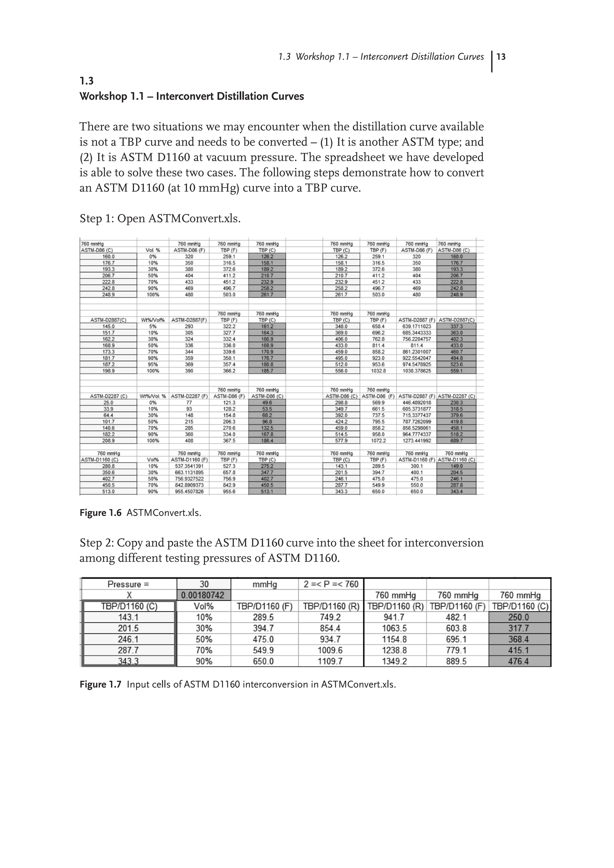
1.3
Workshop 1.1 – Interconvert Distillation Curves
There are two situations we may encounter when the distillation curve available
is not a TBP curve and needs to be converted – (1) It is another ASTM type; and
(2) It is ASTM D1160 at vacuum pressure. The spreadsheet we have developed
is able to solve these two cases. The following steps demonstrate how to convert
an ASTM D1160 (at 10 mmHg) curve into a TBP curve.
Step 1: Open ASTMConvert.xls.
Figure 1.6 ASTMConvert.xls.
Step 2: Copy and paste the ASTM D1160 curve into the sheet for interconversion
among different testing pressures of ASTM D1160.
Figure 1.7 Input cells of ASTM D1160 interconversion in ASTMConvert.xls.
40.
14 1 Characterization,Physical and Thermodynamic Properties of Oil Fractions
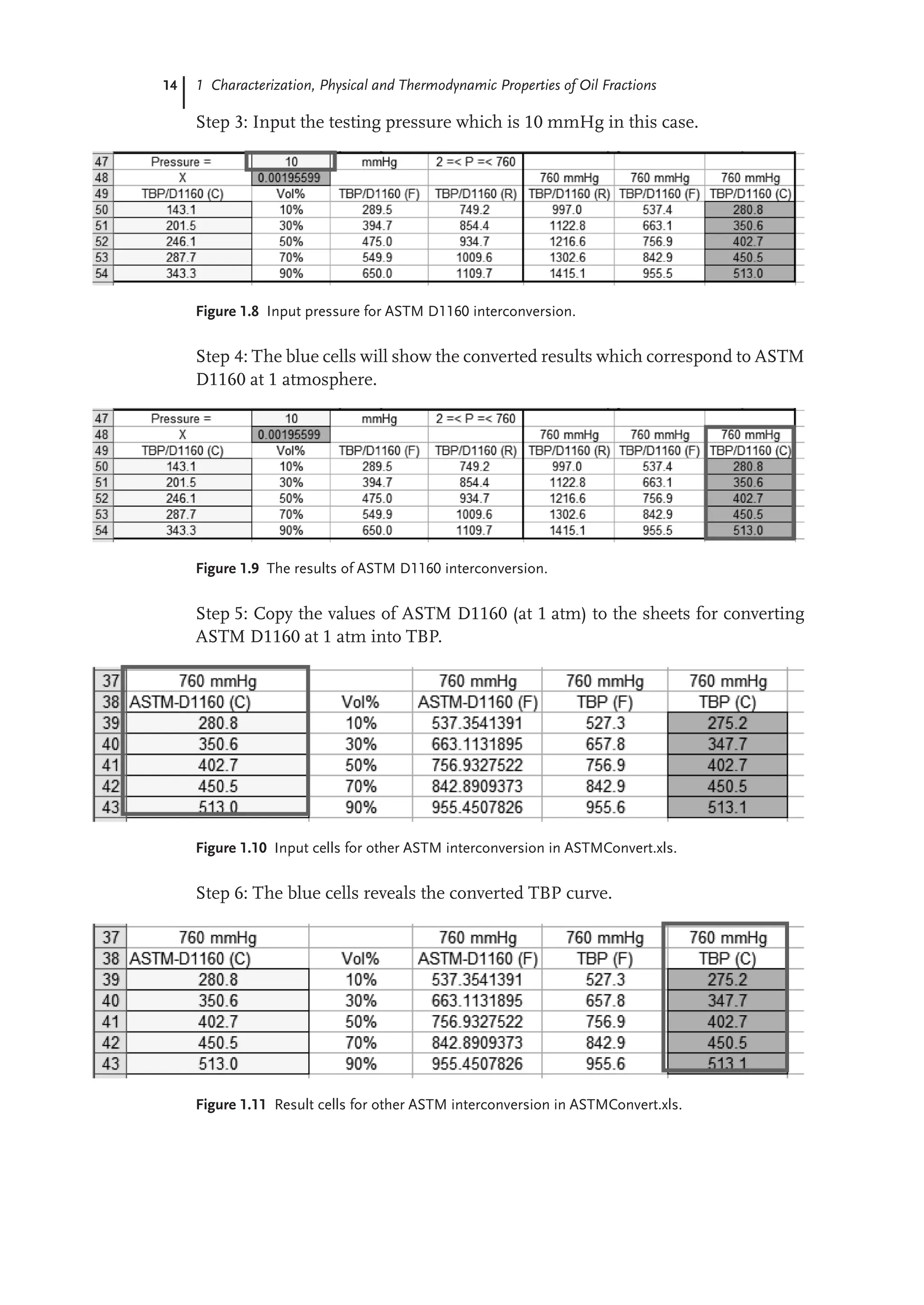
Step 3: Input the testing pressure which is 10 mmHg in this case.
Figure 1.8 Input pressure for ASTM D1160 interconversion.
Step 4: The blue cells will show the converted results which correspond to ASTM
D1160 at 1 atmosphere.
Figure 1.9 The results of ASTM D1160 interconversion.
Step 5: Copy the values of ASTM D1160 (at 1 atm) to the sheets for converting
ASTM D1160 at 1 atm into TBP.
Figure 1.10 Input cells for other ASTM interconversion in ASTMConvert.xls.
Step 6: The blue cells reveals the converted TBP curve.
Figure 1.11 Result cells for other ASTM interconversion in ASTMConvert.xls.
41.
15
1.4 Workshop 1.2– Extrapolate an Incomplete Distillation Curve
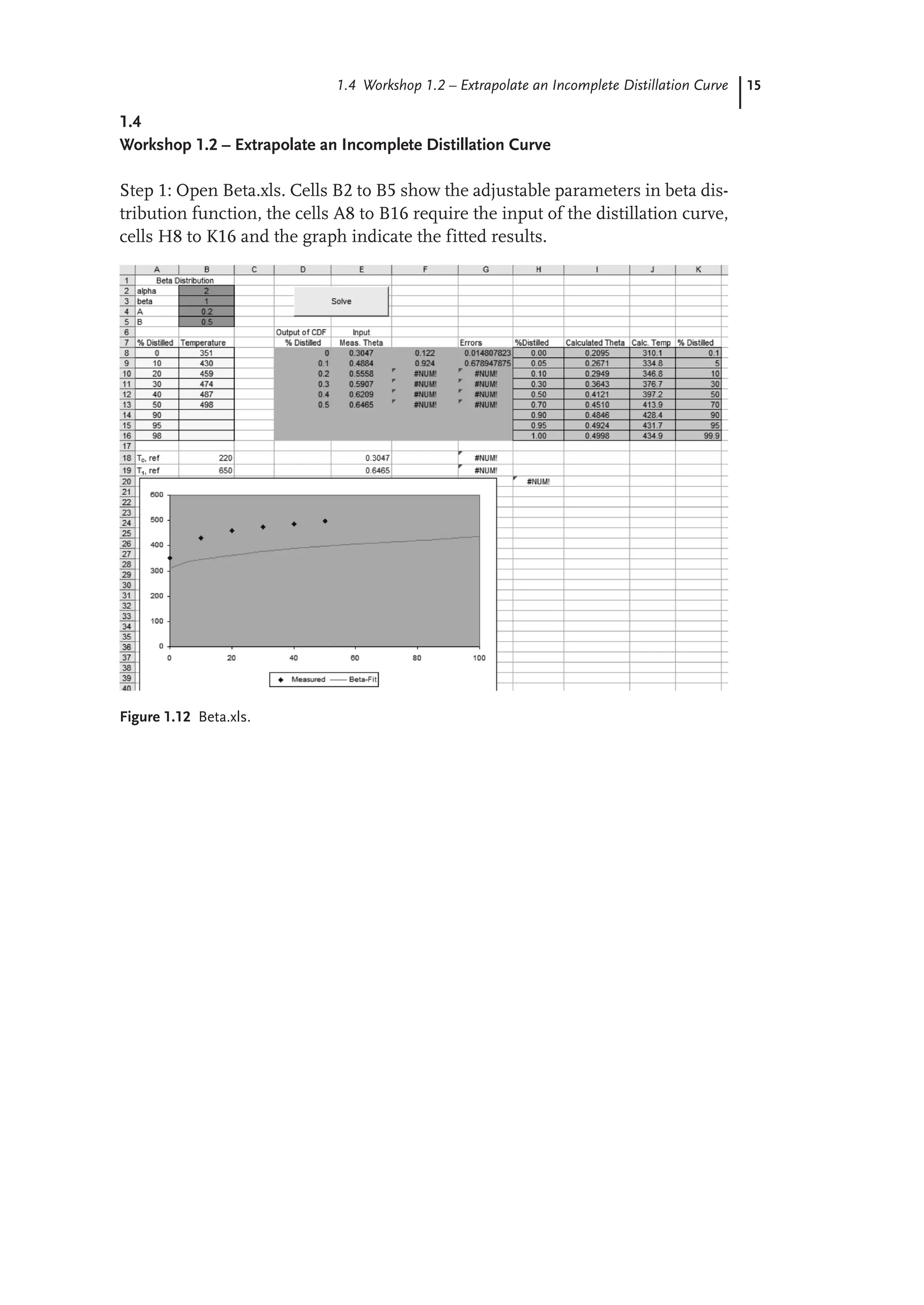
1.4
Workshop 1.2 – Extrapolate an Incomplete Distillation Curve
Step 1: Open Beta.xls. Cells B2 to B5 show the adjustable parameters in beta dis-
tribution function, the cells A8 to B16 require the input of the distillation curve,
cells H8 to K16 and the graph indicate the fitted results.
Figure 1.12 Beta.xls.
42.
16 1 Characterization,Physical and Thermodynamic Properties of Oil Fractions
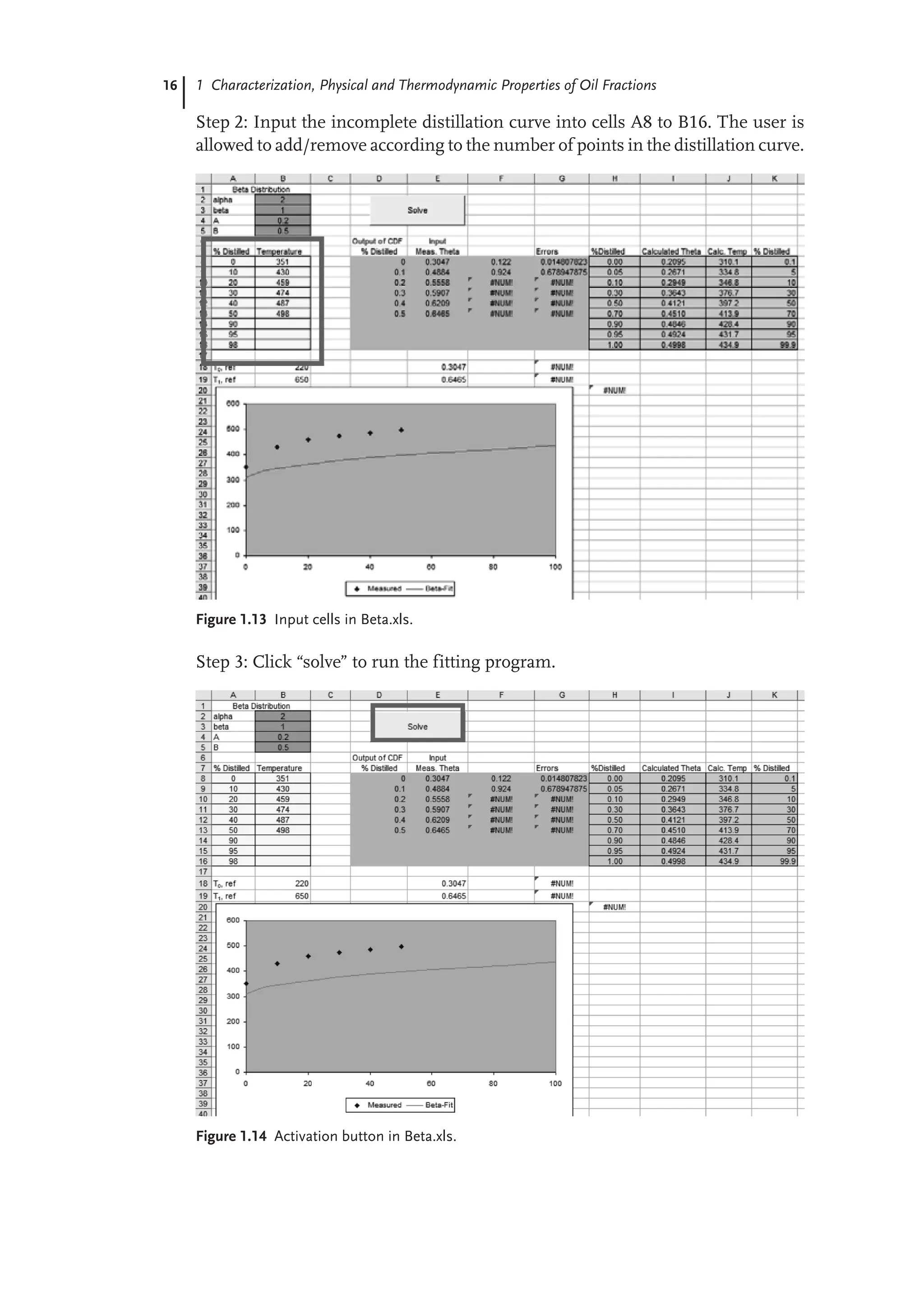
Step 2: Input the incomplete distillation curve into cells A8 to B16. The user is
allowed to add/remove according to the number of points in the distillation curve.
Figure 1.13 Input cells in Beta.xls.
Step 3: Click “solve” to run the fitting program.
Figure 1.14 Activation button in Beta.xls.
43.
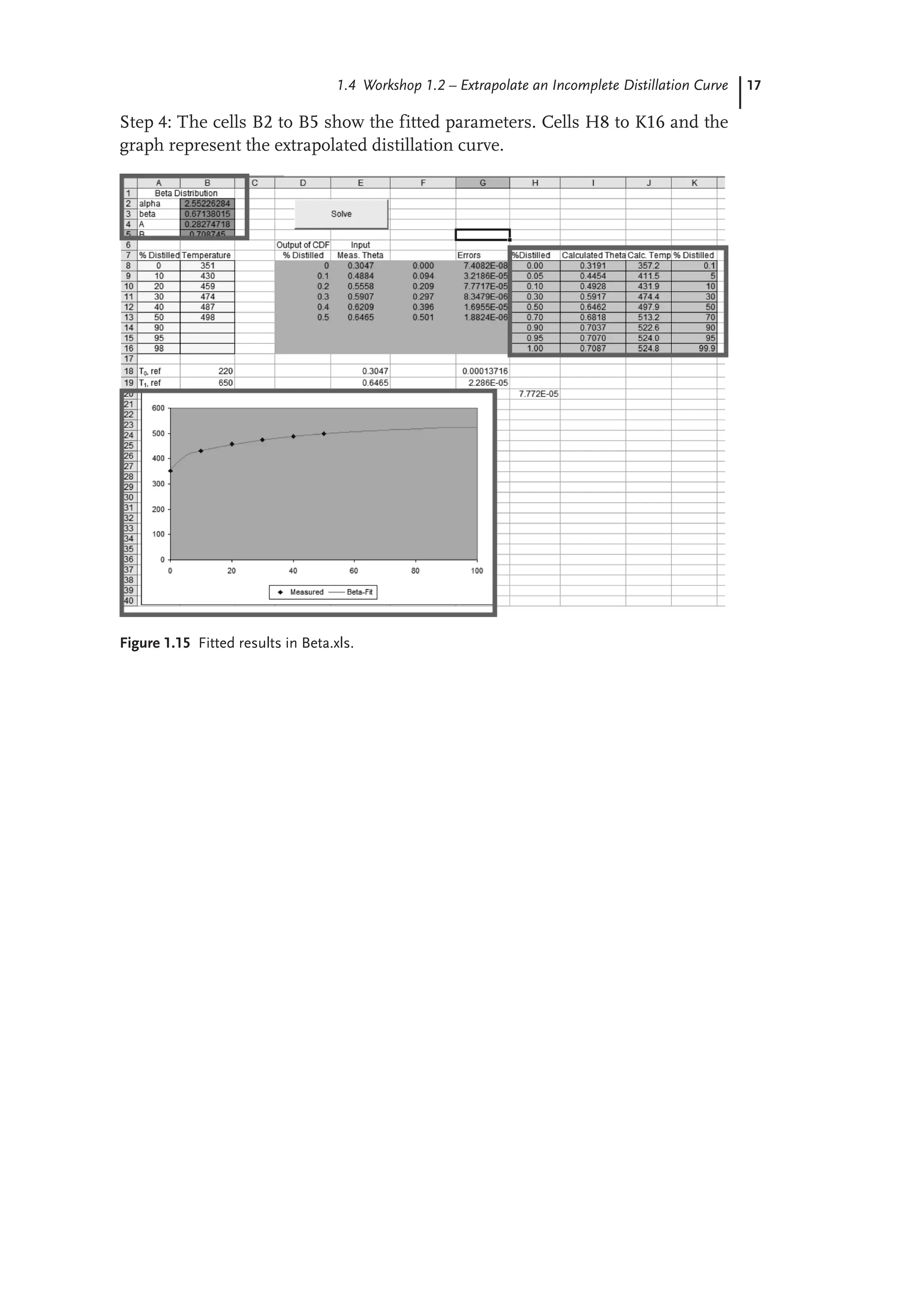
17
1.4 Workshop 1.2– Extrapolate an Incomplete Distillation Curve
Step 4: The cells B2 to B5 show the fitted parameters. Cells H8 to K16 and the
graph represent the extrapolated distillation curve.
Figure 1.15 Fitted results in Beta.xls.
44.
18 1 Characterization,Physical and Thermodynamic Properties of Oil Fractions
1.5
Workshop 1.3 – Calculate MeABP of a Given Assay
Step 1: Open MeABP Iteration.xls.
Figure 1.16 MeABP.xls.
Step 2: Select the type of the oil fraction. We choose naphtha in this case.
Figure 1.17 Select oil type.
45.
19
1.5 Workshop 1.3– Calculate MeABP of a Given Assay
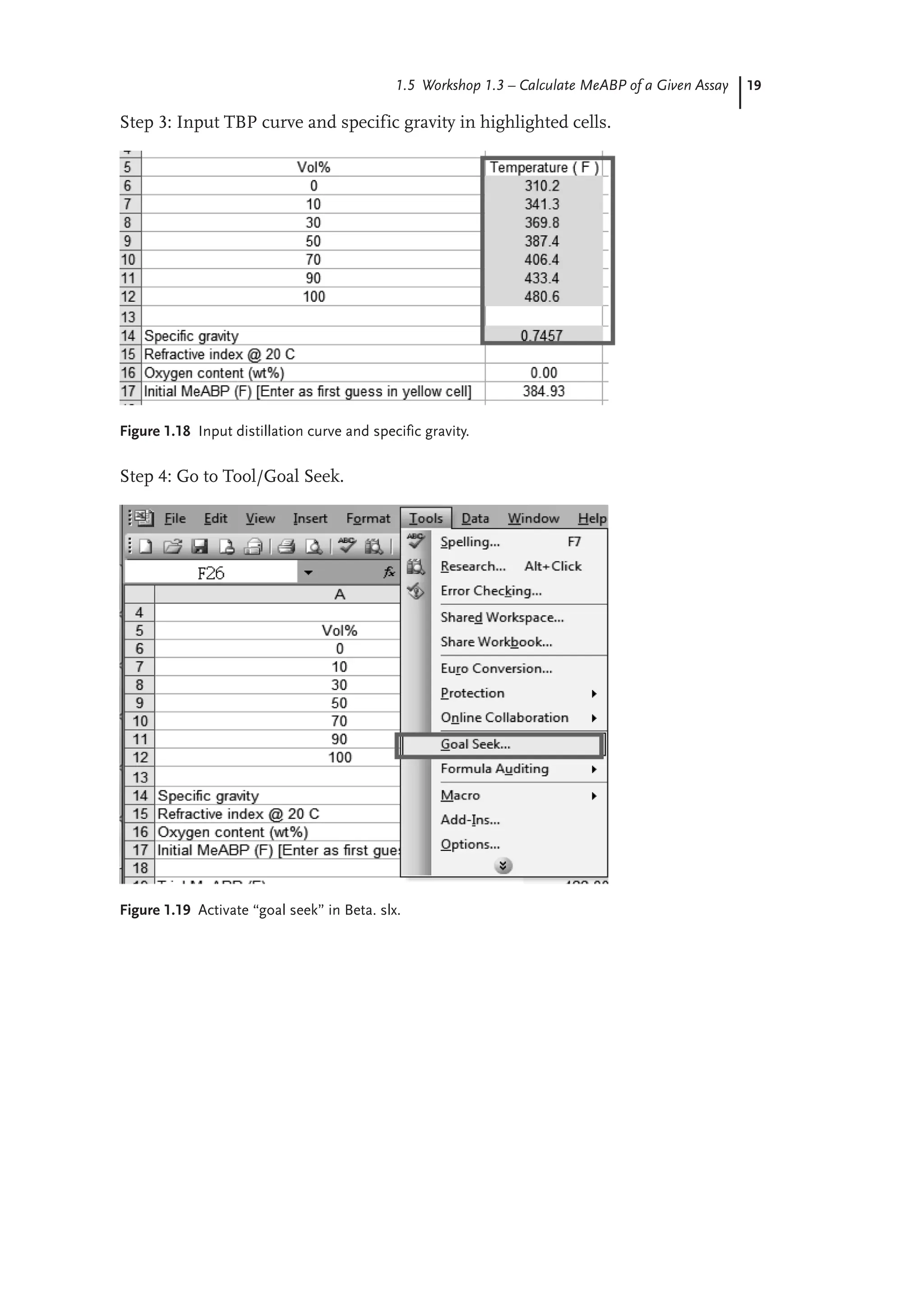
Step 3: Input TBP curve and specific gravity in highlighted cells.
Figure 1.18 Input distillation curve and specific gravity.
Step 4: Go to Tool/Goal Seek.
Figure 1.19 Activate “goal seek” in Beta. slx.
46.
20 1 Characterization,Physical and Thermodynamic Properties of Oil Fractions
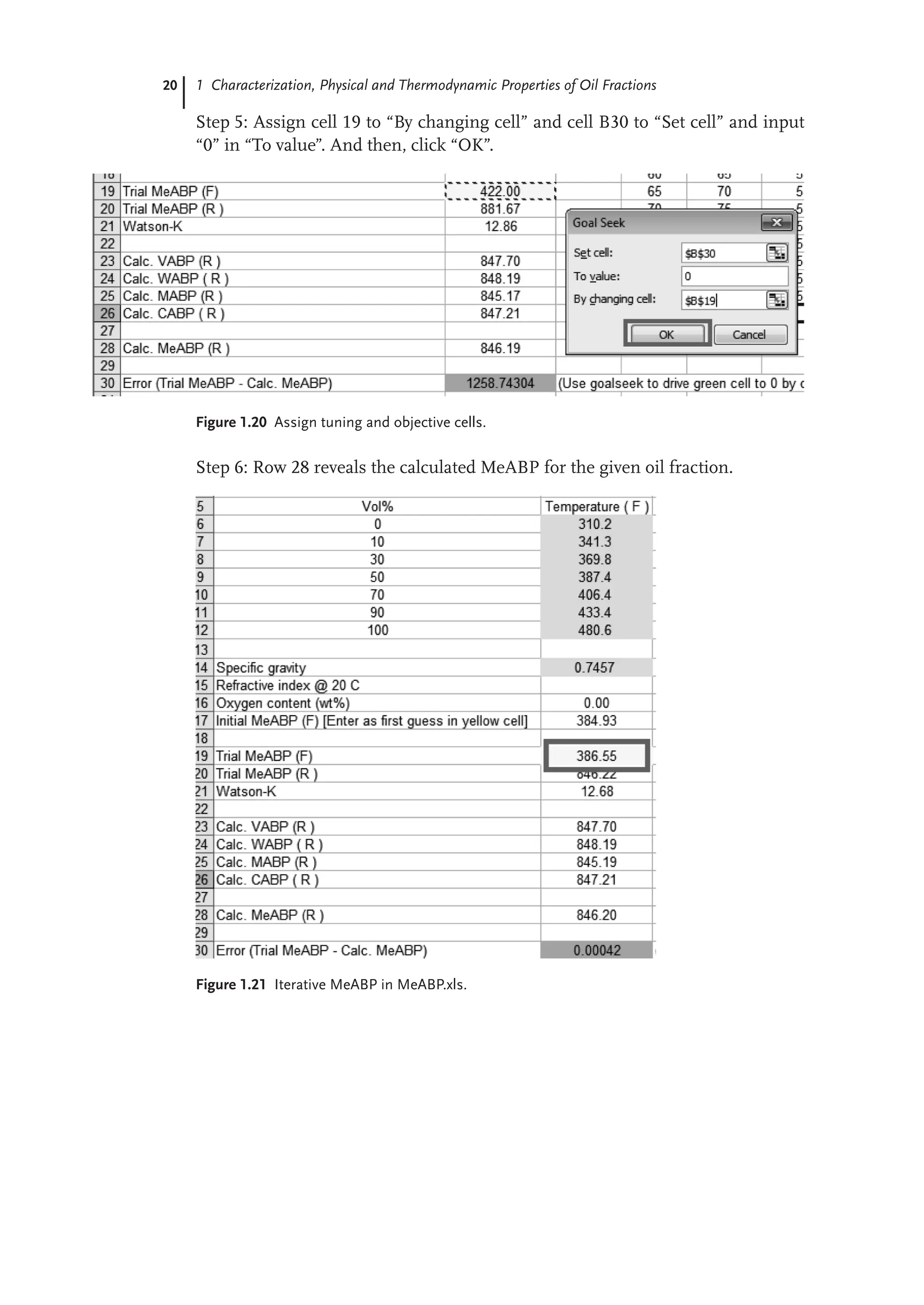
Step 5: Assign cell 19 to “By changing cell” and cell B30 to “Set cell” and input
“0” in “To value”. And then, click “OK”.
Figure 1.20 Assign tuning and objective cells.
Step 6: Row 28 reveals the calculated MeABP for the given oil fraction.
Figure 1.21 Iterative MeABP in MeABP.xls.
47.
21
1.6 Workshop 1.4– Duplicate the Oil Fraction in Aspen HYSYS Petroleum Refining
1.6
Workshop 1.4 – Duplicate the Oil Fraction in Aspen HYSYS Petroleum Refining
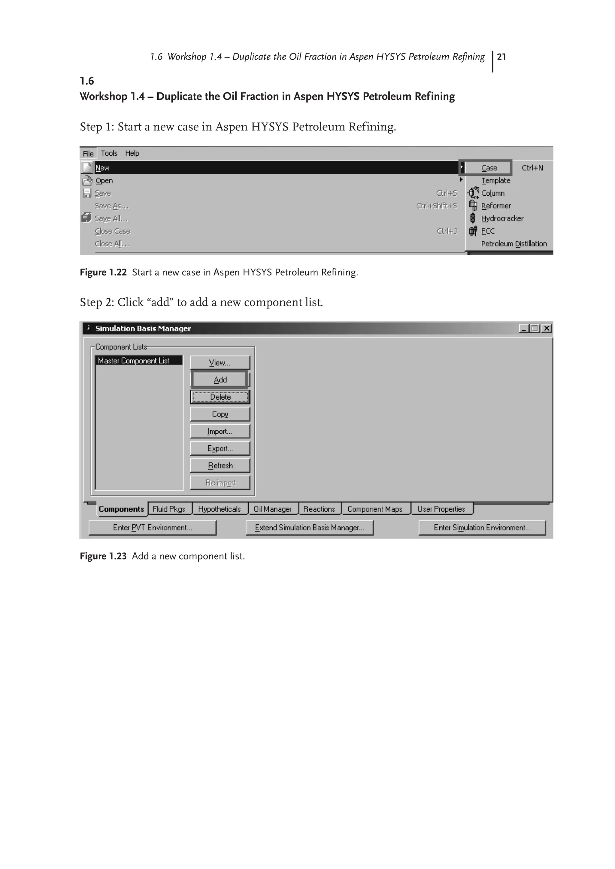
Step 1: Start a new case in Aspen HYSYS Petroleum Refining.
Figure 1.22 Start a new case in Aspen HYSYS Petroleum Refining.
Step 2: Click “add” to add a new component list.
Figure 1.23 Add a new component list.
48.
22 1 Characterization,Physical and Thermodynamic Properties of Oil Fractions
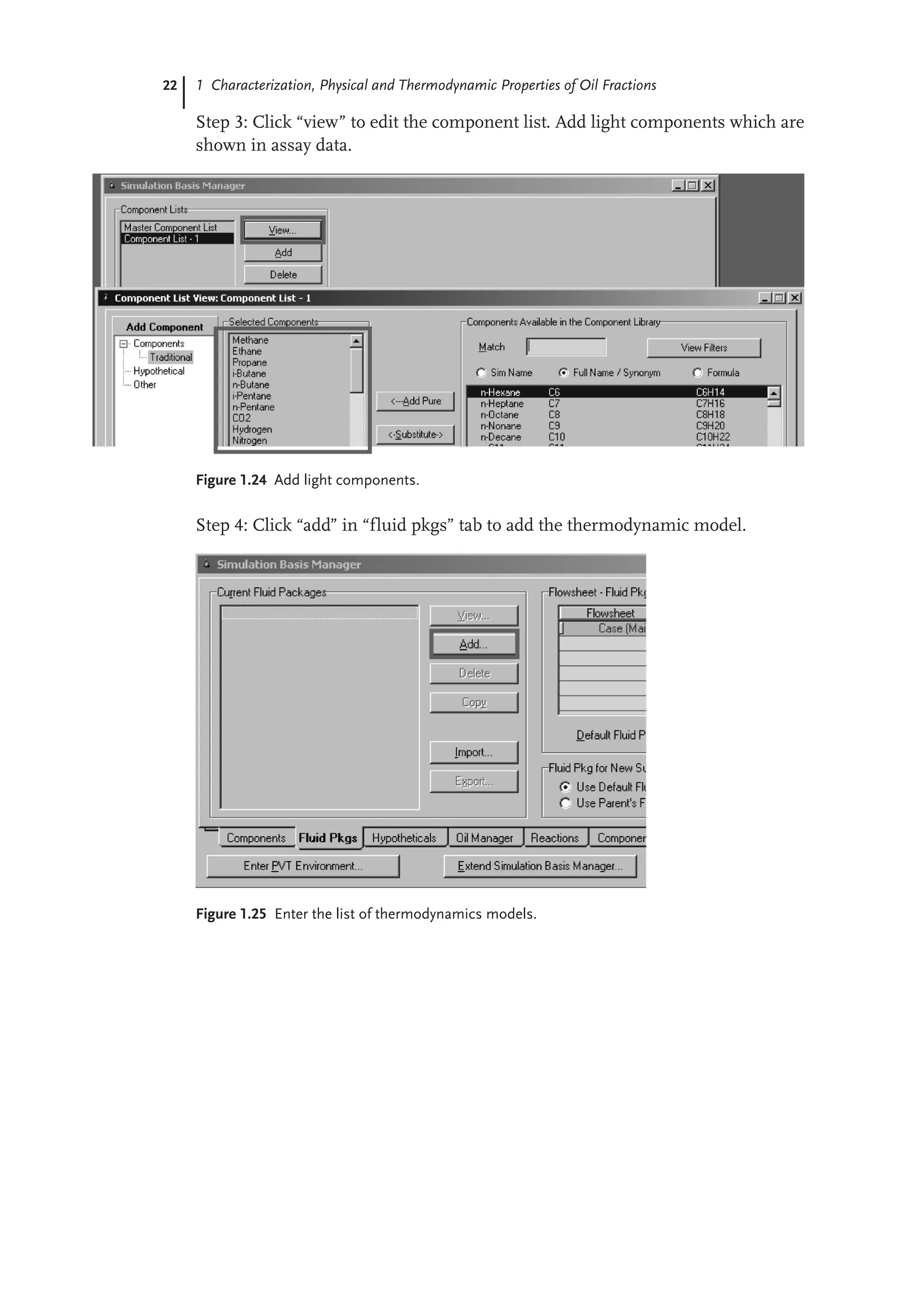
Step 3: Click “view” to edit the component list. Add light components which are
shown in assay data.
Figure 1.24 Add light components.
Step 4: Click “add” in “fluid pkgs” tab to add the thermodynamic model.
Figure 1.25 Enter the list of thermodynamics models.
49.
23
1.6 Workshop 1.4– Duplicate the Oil Fraction in Aspen HYSYS Petroleum Refining
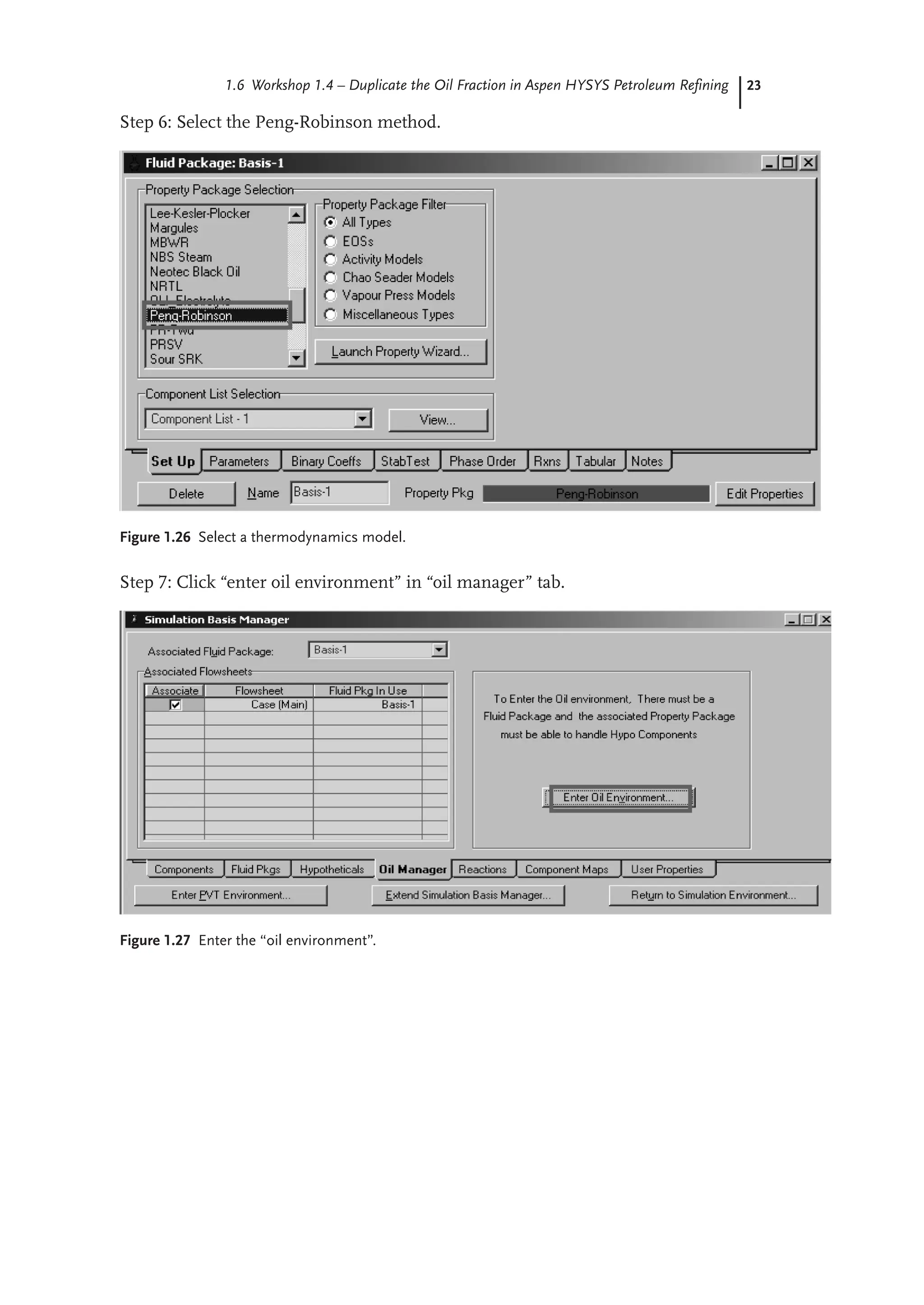
Step 6: Select the Peng-Robinson method.
Figure 1.26 Select a thermodynamics model.
Step 7: Click “enter oil environment” in “oil manager” tab.
Figure 1.27 Enter the “oil environment”.
50.
24 1 Characterization,Physical and Thermodynamic Properties of Oil Fractions
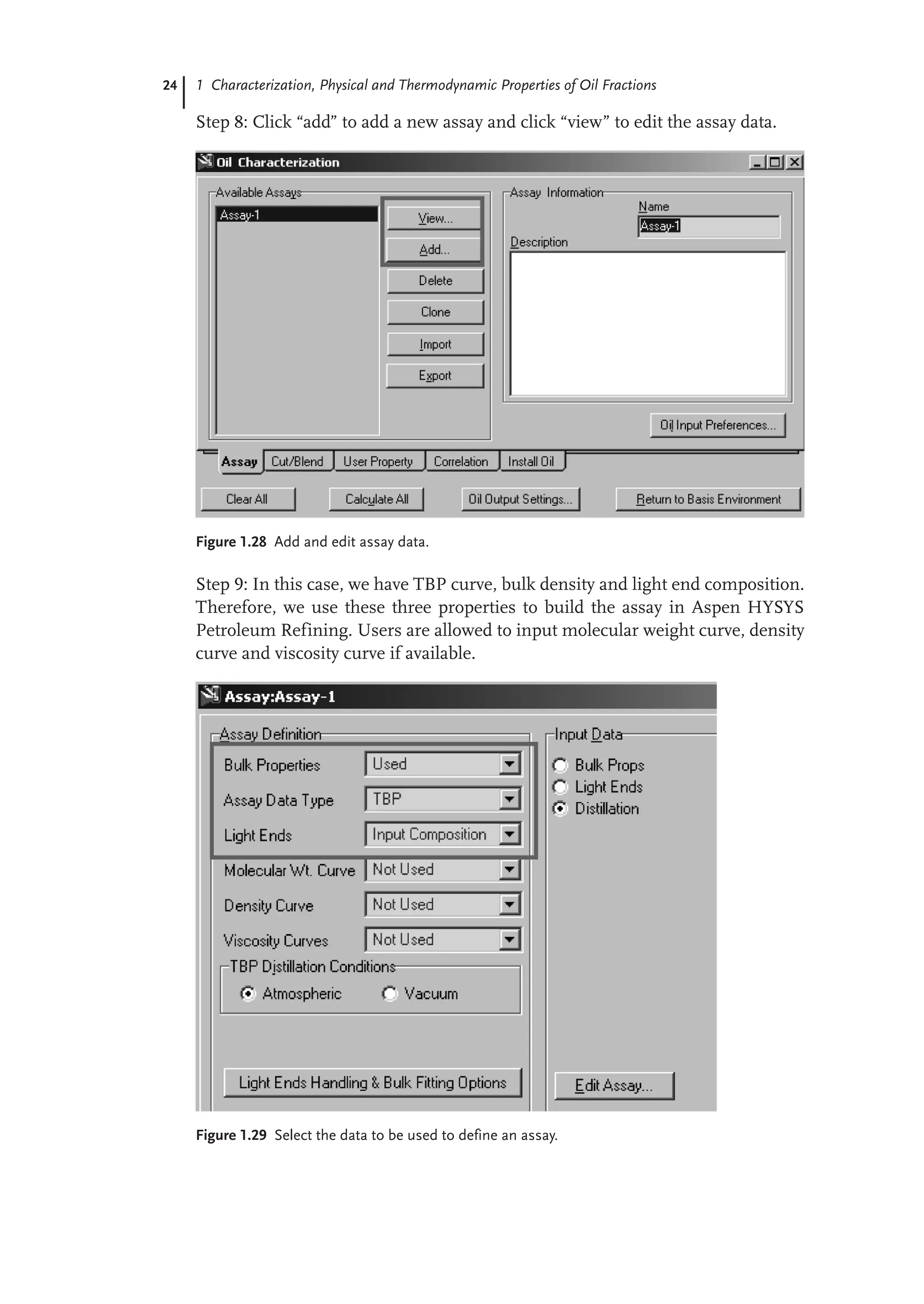
Step 8: Click “add” to add a new assay and click “view” to edit the assay data.
Figure 1.28 Add and edit assay data.
Step 9: In this case, we have TBP curve, bulk density and light end composition.
Therefore, we use these three properties to build the assay in Aspen HYSYS
Petroleum Refining. Users are allowed to input molecular weight curve, density
curve and viscosity curve if available.
Figure 1.29 Select the data to be used to define an assay.
51.
25
1.6 Workshop 1.4– Duplicate the Oil Fraction in Aspen HYSYS Petroleum Refining
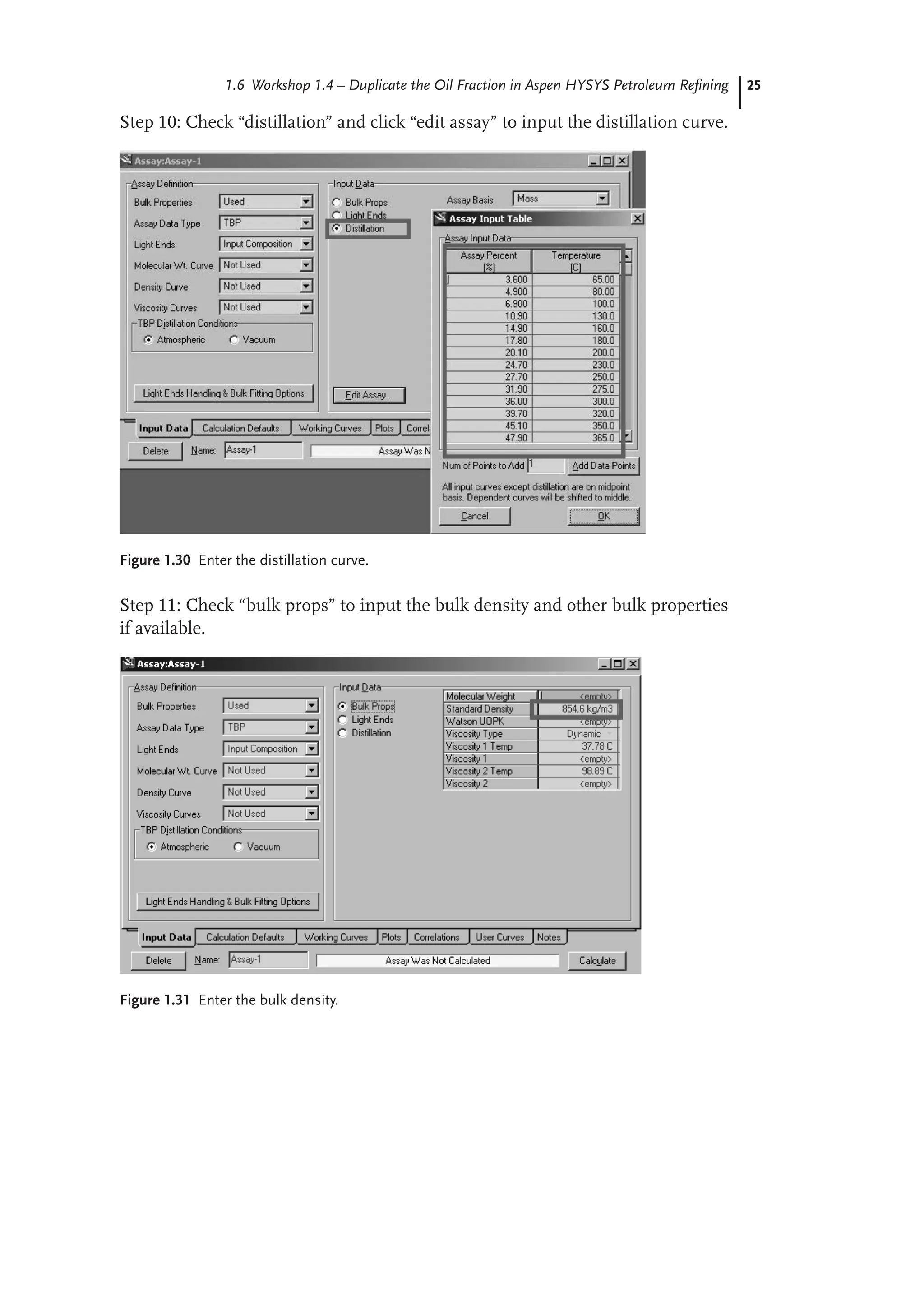
Step 10: Check “distillation” and click “edit assay” to input the distillation curve.
Figure 1.30 Enter the distillation curve.
Step 11: Check “bulk props” to input the bulk density and other bulk properties
if available.
Figure 1.31 Enter the bulk density.
52.
26 1 Characterization,Physical and Thermodynamic Properties of Oil Fractions
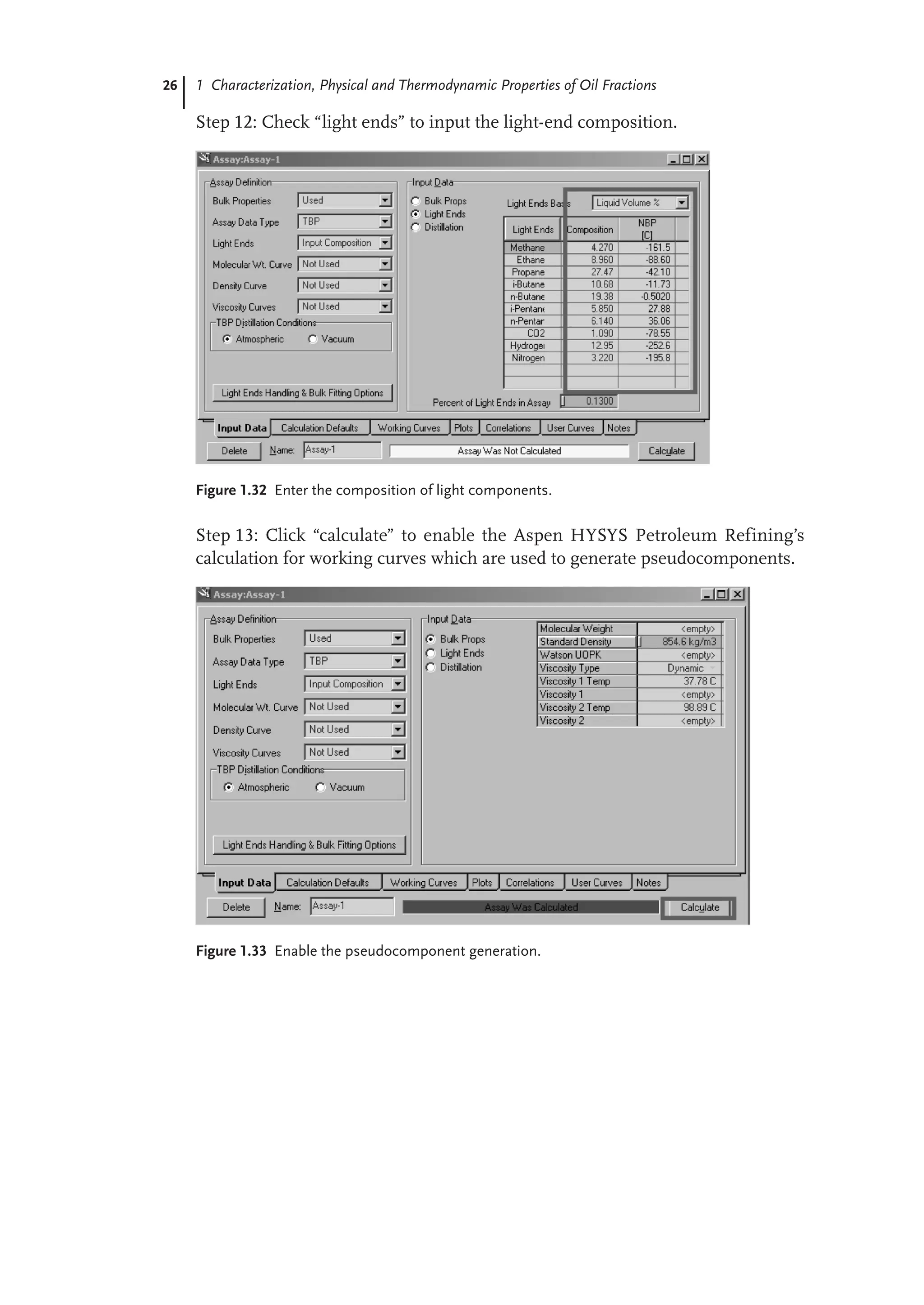
Step 12: Check “light ends” to input the light-end composition.
Figure 1.32 Enter the composition of light components.
Step 13: Click “calculate” to enable the Aspen HYSYS Petroleum Refining’s
calculation for working curves which are used to generate pseudocomponents.
Figure 1.33 Enable the pseudocomponent generation.
53.
27
1.6 Workshop 1.4– Duplicate the Oil Fraction in Aspen HYSYS Petroleum Refining
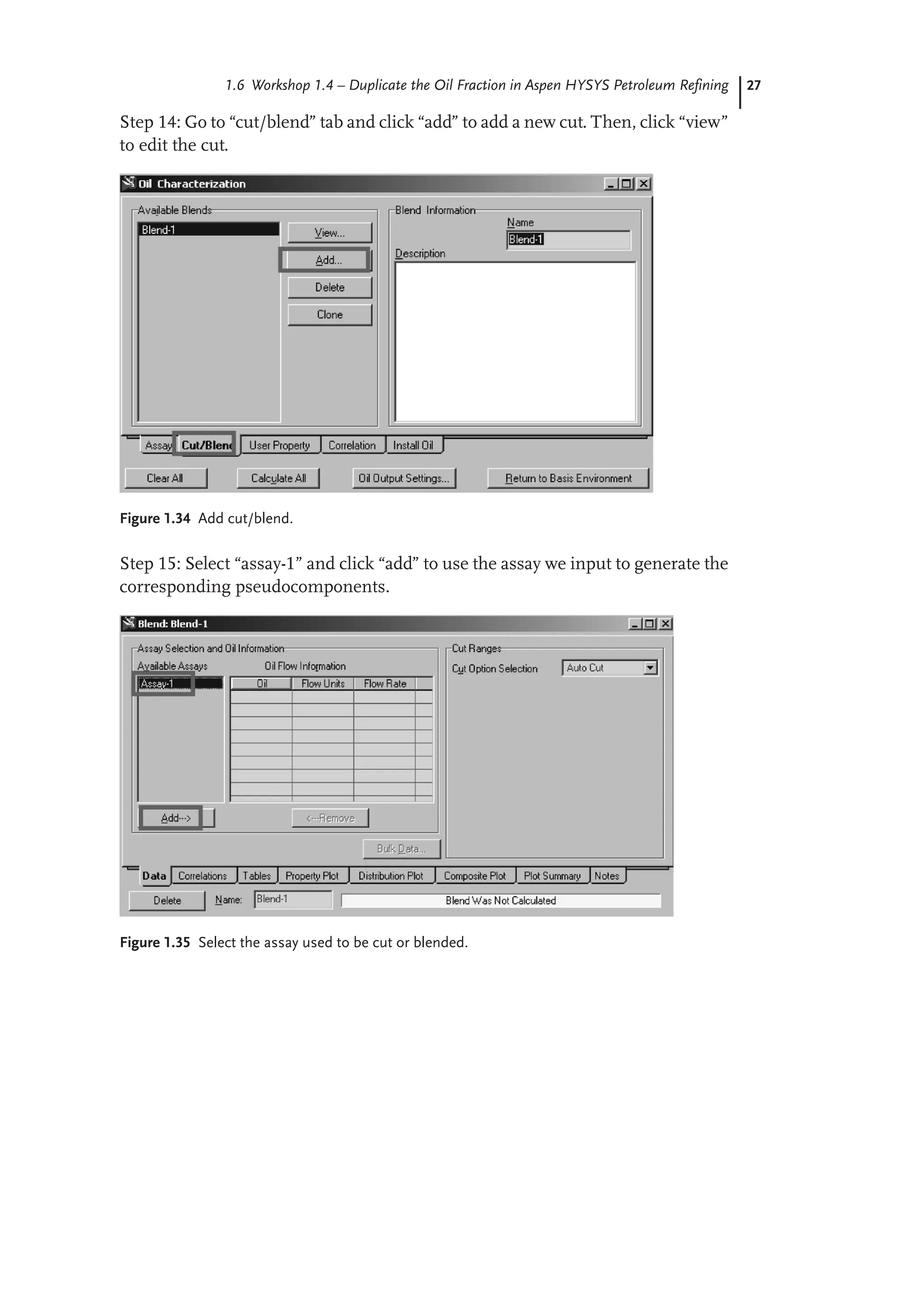
Step 14: Go to “cut/blend” tab and click “add” to add a new cut. Then, click “view”
to edit the cut.
Figure 1.34 Add cut/blend.
Step 15: Select “assay-1” and click “add” to use the assay we input to generate the
corresponding pseudocomponents.
Figure 1.35 Select the assay used to be cut or blended.
54.
28 1 Characterization,Physical and Thermodynamic Properties of Oil Fractions
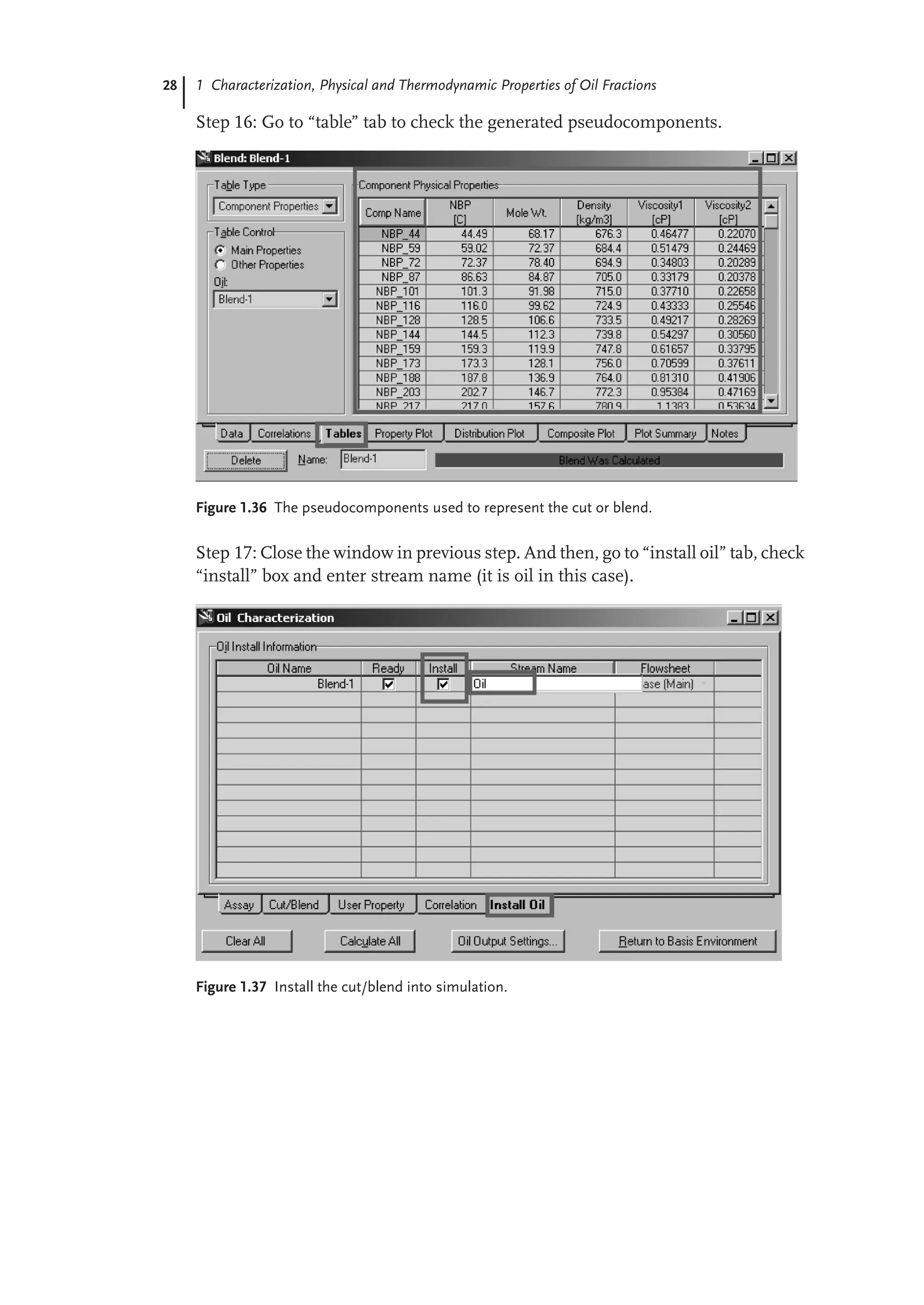
Step 16: Go to “table” tab to check the generated pseudocomponents.
Figure 1.36 The pseudocomponents used to represent the cut or blend.
Step 17: Close the window in previous step. And then, go to “install oil” tab, check
“install” box and enter stream name (it is oil in this case).
Figure 1.37 Install the cut/blend into simulation.
With your permissionI would gladly commence recruiting in
these areas, and form a new battalion here. For the purpose of
enlisting the Palestine volunteers, it would require a recruiting
party to make a trip round the Jewish colonies to collect the
recruits. I have an ideal party for such a duty in my present
battalion, all speaking Hebrew, headed by an officer who knows
Palestine. With your approval I would send this party as soon as
possible on tour. Recruiting offices should also be opened in
Cairo and Alexandria, where I have promises of every support
from the Jewish communities of these cities.
In England the Adjutant-General allowed transfers of Jewish
Officers, N.C.O.'s and men. I hope you will be equally indulgent
to those who wish to join me from other units now under your
command.
I am strongly of the opinion that the training ground of the
Jewish Brigade should be in Judæa itself, firstly for its great
moral effect on the men; secondly, the climate of Cairo during
the training months of March and April will make it practically
impossible to do much satisfactory work here. I am convinced
that twice the results could be obtained in such a place as Jaffa,
or other suitable colony, while the health of the troops would
greatly benefit by the cooler climate. It would also enormously
stimulate recruiting in Palestine.
I know that the Home Government attach the greatest
importance to the moral effect of this Jewish Brigade on the
outer world of Jewry—not only in allied and neutral, but also in
enemy countries—and such full effect can only be obtained by
placing the Brigade in Palestine at the earliest possible moment.
There are some other points which I would like to bring to your
notice, but I will not add to the length of this letter by
mentioning them now.
I should, however, be very glad to see you, and discuss these
matters generally with you, and hope you will send instructions
57.
for me toreport at your headquarters at an early date.
Yours sincerely,
(Signed) J. H. Patterson.
I got a reply from Major-General Louis Jean Bols, the Chief of Staff,
asking me to come to G.H.Q., but at the same time informing me
that General Allenby was not in favour of my suggestions.
This was somewhat of a surprise to me, for at a time when men
were so badly needed, I thought that a Jewish legion, of say 25,000
men, would have been most acceptable on the Palestine front, and,
had General Allenby shown himself at all favourable to the idea of a
Jewish legion, it would at that time have been an easy task to have
obtained any number of men, from America and elsewhere, to fight
in Palestine.
Nothing daunted, however, I proceeded to G.H.Q., where I had an
interview with the Commander-in-Chief, who told me quite frankly
that he was not in sympathy with the War Office policy in sending
this Jewish Battalion to Palestine, and that he did not want any
further addition such as I suggested to his Forces.
At a subsequent interview which I had with his Chief of Staff, I
gathered that I need expect but little sympathy for my battalion, as
Major-General Louis Jean Bols told me quite plainly that he was not
favourably disposed towards Jewish aspirations.
This anti-Jewish policy of General Allenby and his Chief of Staff came
as a shock to me, for I knew that it was the settled intention of His
Majesty's Government to support these Jewish Battalions, and the
Jewish claim to Palestine, and I had been expecting quite a different
reception for my proposals from the E.E.F. authorities to that which
they received. I found, to my amazement, that the policy adopted by
the Staff towards this Jewish Battalion, and the Jewish problem
generally, ran counter to the declared policy of the Home
Government. Alas! it seemed that another Pharaoh had arisen who
knew not Joseph; and once again we would be expected to make
bricks without straw, and become hewers of wood and drawers of
58.
water. Instead ofthis new unit being helped and encouraged, we
were, on the contrary, throughout our service in the E.E.F., made to
feel that we were merely Ishmaelites, with every hand uplifted
against us.
I knew full well what our fate would be once the policy of G.H.Q. on
this question was known, and, as I will show later, the underlings of
the Staff did not fail to play up to the attitude of the higher
command. I hoped, however, that the battalion would do such good
work that we would eventually overcome all prejudice. We looked for
no favours, and only wanted to be treated as a battalion "all out" to
do its duty.
The Commander-in-Chief was of course aware by this time of the
Arab pretensions to Syria, and as his mind was, no doubt, wholly
centred on his own war theatre, he was naturally anxious to placate
the Arab at all costs. The Arab was at his door, giving him certain
assistance by harrying the Turks to the East of the Jordan, and the
fact that the Hedjaz Army was fighting on our side kept Bedouins
and other marauders from interfering with our lines of
communication—no small matter in Palestine and Syria. The
intrusion of the Jew was a disturbing factor to his policy, and was
therefore resented.
The local Military Authorities, however, seemed oblivious of the fact
that there was a much bigger question involved than that which
loomed so largely in their eyes on the Palestine horizon. There was
England's world policy to be considered, and her Statesmen had
already decided that it was very much in her interests to win over to
her side Jewish help and sympathy the world over. Let no one under-
estimate what that help meant to the Allies during the Great War.
The Jewish element, owing to the Balfour Declaration, came solidly
to our side in every land, and in America greatly helped to counter
the German propaganda which was fast gripping hold of the United
States. It was unfortunate that this far-sighted and wise policy of our
Imperial Statesmen was never grasped by their local agents in
Palestine.
59.
In the E.E.F.,so far as one on the spot could judge, but scant heed
was paid to any policy unless it bore on local affairs and coincided
with the point of view held by G.H.Q. and the satellites revolving
round it.
If only a little wise diplomacy had been employed, I am strongly of
the opinion that it would have been quite practicable for the local
authorities to have treated the Jewish problem fairly and on the lines
of the Balfour Declaration and, at the same time, have retained the
Arabs on our side. After all the Arabs were as much interested in the
downfall of the Turk as we were ourselves, and, to his honour be it
said, the Emir Feisal never showed himself hostile to Jewish
aspirations. On the contrary he expressed the utmost goodwill and
worked hand in hand with Dr. Weizmann for the common good of
both peoples.
The Jew and the Arab are necessary to each other in the Near East,
and if England wishes to retain her Empire it is vital to her interests
to keep friendly with both. I am afraid that at the moment we are at
a discount to the East of Suez. During the stress of war certain
promises were made to the Arabs which appear difficult to redeem,
mainly due to the policy of France in Syria. I admire France
immensely, and that is why I so much deplore her imperialistic aims
beyond the Lebanons. She is sowing a rich crop of troubles for
herself in these regions, and I am certain that ere long we shall see
her reaping a bitter harvest. I met a much travelled French officer in
Cairo, who had just relinquished an administrative post in Beyrout,
and he told me that, if his Government was wise, it would clear out
of Syria, where it would have nothing but trouble for generations to
come. "If only," he went on, "England would give us a bit of Africa
and take Syria instead, France would make a good bargain."
We, however, do not want Syria, but we do want to see a strong and
settled Arab state in these strictly Arab regions, and I sincerely hope
that our Statesmen will be wise enough, and energetic enough, to
bring about such a desirable consummation. If we permit the
Bolshevists and Turks to oust us from our friendship with the Jews
60.
and Arabs, andwith King Hussein and his son the Emir Feisal (now
the King of Irak), upon whom we have alternately blown hot and
cold, just as it pleased France to pipe the tune then we shall witness
the beginning of the end of our power and prestige in the Orient.
My trip to G.H.Q. was not quite in vain, for just before we left Egypt
sanction was given to enlist Palestinian volunteers. I sent to Judæa a
specially trained recruiting party, all fluent Hebrew speakers, under
the command of Lieutenant Lipsey, to report to Major James de
Rothschild of the 39th Battalion, who was the officer appointed to
supervise this work in Egypt and Palestine.
The response to Major de Rothschild's appeal was enthusiastic—in
fact his chief trouble was to keep out grey-beards and unfledged
youths, so eager were all to join up.
Lieutenant Lipsey had some difficulty in keeping his end up in
Jerusalem, where there were many anti-Zionists, but finally he
worsted his opponents and emerged triumphant with nearly 1,000
recruits.
The following is a translation of the Hebrew recruiting poster sent
throughout Palestine at this time:—
Hear, O Israel!
Hear! What does your heart prompt you to do?
Shall we not reclaim our heritage and establish its
possession
in the eyes of the world?
Hearken! What does your reason say to you?
The British are fighting here before our eyes, and shall
we remain in our houses until they return from
the
battle to give us our country which they have
redeemed
with their blood?
Hearken! What does your honour and conscience
61.
dictate?
Is it possiblefor us to accept from the hands of our
righteous redeemers such an offering of blood?
Shall not we too, together with them, offer our lives
for our country?
Hear, O Israel!
The blood of our heroic forefathers, the blood of the
British who fight for us this day, and the blood
of
the martyrs, cry unto us from this sacred
ground.
Enlist! Enlist!
Shoulder to shoulder, together with our saviours, to
the
battle let us go. And salvation is with the Lord.
Be Strong!
62.
CHAPTER VIII.
The Feastof the Passover.
At this time G.H.Q. was situated at a place called Bir Salem (the Well
of Peace), ten miles to the east of Jaffa, and as, after my interview, I
had the whole day before me, I borrowed a motor-car and paid a
flying visit to Jerusalem, some thirty miles away to the eastward. I
will not attempt to describe here what I felt as I approached the
Holy City, along the winding road which leads up to it through the
rocky Judæan mountains.
I entered the old walled city through the Jaffa Gate, and was soon
buried in its gloomy bazaars and labyrinthine passages, seeking out
the old historic spots which I had reverenced from the days of my
youth. I had but a few hours for my explorations, but they were
about the busiest hours I ever spent, and although I have paid many
visits to Jerusalem since that date I have not forgotten the glamour
thrown over me by my first visit to these sacred shrines and temples
of antiquity.
I left Jerusalem at three in the afternoon and was back in my camp
at Helmieh within twenty-four hours.
63.
JERUSALEM
The Battalion wasattached to the School of Instruction at Zeitoun
(close to Helmieh), which was an unfortunate arrangement, for our
requirements were not attended to, and we were often kept idle for
long periods owing to want of equipment, such as rifles, etc., to
enable the men to fire their musketry course. There was no excuse
for this, for there was plenty of equipment of all kinds in the
Ordnance Stores at Cairo. It was the fault of the vicious system of
having to get everything we wanted through the School of
Instruction, whose staff did not seem to think that our requirements
needed speeding up. It was not until Brigadier-General A. B.
Robertson assumed command of the school that matters were
mended, for this officer took a very friendly interest in us and did
everything in his power to help us along.
The Feast of the Passover was celebrated during our stay at
Helmieh. Thus history was repeating itself in the Land of Bondage in
a Jewish Military Camp, after a lapse of over 3,000 years from the
date of the original feast.
I had considerable trouble with the authorities in the matter of
providing unleavened bread. However, we surmounted all difficulties,
and had an exceedingly jovial first night, helped thereto by the
excellent Palestinian wine which we received from Mr. Gluskin, the
head of the celebrated wine press of Richon-le-Zion, near Jaffa. The
unleavened bread for the battalion, during the eight days of the
Feast, cost somewhat more than the ordinary ration would have
done, so I requested that the excess should be paid for out of Army
Funds. This was refused by the local command in Egypt, so I went
to the H.Q. Office, where I saw a Jewish Staff Officer, and told him I
had come to get this matter adjusted. He said that, as a matter of
fact, he had decided against us himself. I told him that I considered
his judgment unfair, because the battalion was a Jewish Battalion,
and the Army Council had already promised Kosher food whenever it
was possible to obtain it, and it would have been a deadly insult to
64.
have forced ordinarybread upon the men during Passover. I
therefore said that I would appeal against his decision to a higher
authority. He replied, "This will do you no good, for you will get the
same reply from G.H.Q." He was mistaken, for I found the Gentile,
on this particular occasion, more sympathetic than the Jew, and the
extra amount was paid by order of the Q.M.G., Sir Walter Campbell.
During our stay at this camp we were reviewed by H.R.H. the Duke
of Connaught, and, towards the end of May, by the Commander-in-
Chief, General Allenby. Both these officers expressed themselves as
pleased with the smart soldierly appearance and steadiness of the
men, the Duke of Connaught remarking that "the men all appeared
to be triers."
Towards the close of our training at Helmieh, and just as I was
beginning to congratulate myself that the battalion was shaping well
and would soon be fit for the front, I was staggered by the receipt of
a letter from G.H.Q. which aimed a deadly blow at our very
existence. It was nothing less than the proposal to break up the
battalion and allow the men to join Labour units! This was
undoubtedly a clever move on the part of the Staff to rid themselves
of the Jewish problem and, at the same time, bring the derision of
the world upon the Jew.
THE BATTALION ON PARADE
65.
TOMB OF RACHEL,NEAR BETHLEHEM
(See page 93)
It put me in a very difficult position, for I felt very keenly that, if the
battalion were disbanded and turned over to Labour units, it would
throw an indelible stigma on Jewry.
I felt that it was my duty to protect the battalion from the disgrace
that would attach to it if it could be said that the only Jewish unit
raised for war purposes had refused to fight—even for Palestine.
I therefore ordered a parade of the men by Companies, and got the
officers to point out to the men their sacred duty, and gave
instructions for any malcontents to be sent before me for a final
appeal. Only twelve men were found who wished to join a Labour
unit, and to these twelve (I thought the number appropriate, as it
was one for each tribe) I made a strong personal appeal, and after I
had pointed out, in the best language at my command, what a
stigma they were placing on the battalion, and on their fellow Jews
throughout the world, ten saw the error of their ways and cheerfully
said they wished to do their duty as soldiers, and continued serving
with the battalion, and I am glad to be able to place on record that
66.
these ten didvery well afterwards in the field, one of them making
the supreme sacrifice. Two only remained obdurate to all appeals,
and insisted on being posted to a Labour unit, and I think Jewry
should remember them to all time. Their names and numbers, and
the evil which they did, are recorded in the chronicles of the
battalion. They were turned out of the camp and drafted to a Labour
unit at a moment's notice, just as if they had been lepers.
Towards the end of April, 1918, we were delighted to welcome the
39th Battalion from England, under the command of Lieut.-Colonel
Margolin, D.S.O., and with them as M.O. I was glad to see Captain R.
Salaman. We gave the new arrivals a very hearty welcome, the band
of the 38th Battalion playing them into Camp amid great
enthusiasm.
There was much friendly rivalry between these Jewish Battalions,
and honours were about easy in our sporting competitions. We gave
one or two "At Homes," to which all Cairo seemed to flock, and I am
sure our good Cairene friends were favourably impressed with what
they saw of the Jewish Battalions at work and play.
Just about this time we were visited at Helmieh by Dr. Weizmann,
Mr. Joseph Cowen, and Mr. Aaronson. All three gave addresses to
the men. Mr. Aaronson moved his audience to fury by graphically
describing the torture which the Turks had inflicted on his aged
father and young sister in Palestine, because they had dared to help
England. Mr. Aaronson lived to see his home land freed from the
Turk, but soon afterwards lost his life in an aeroplane disaster while
crossing from England to France.
Dr. Weizmann has done much and suffered much since he addressed
us on that peaceful evening in the Egyptian desert. If he could have
foreseen everything I doubt if even his undaunted soul would have
faced unblenched all the trials and tribulations which have fallen to
his lot since he undertook the arduous task of leading his people
back to the Land of Israel. His task has been, if anything, more
difficult than was that of the great Lawgiver. The latter had only to
67.
surmount the obstinacyof one Pharaoh, while Dr. Weizmann had to
overcome that of thousands—not a few of them being Jews!
What a pity it was that the modern leader had not the power to
dispense a few of the plagues which Moses eventually found so
efficacious. It is a striking testimonial to the genius of Dr. Weizmann
that so much has already been accomplished towards the
Restoration; the fact that the Jewish people are now within sight of
their hearts' desire is, without doubt, mainly due to the patient,
persistent, and able diplomacy of this brilliant leader.
It must not be forgotten, however that he was at all times, and
often in the teeth of bitter opposition, given the ready help and
sympathy of Mr. Lloyd George and Sir Arthur Balfour.
68.
CHAPTER IX.
We SetOut for the Front.
By the end of May our training was completed and on the 5th June,
1918, we left Egypt for Palestine, getting a very hearty "send-off"
from Col. Margolin and the 39th Battalion.
Before we set out I had the gratification of receiving from General
Robertson the following letter:
Savoy Hotel,
Cairo,
4th June, 1918.
Dear Colonel Patterson,
On the eve of your departure for the front I desire to wish you
and the officers and men of the 38th Royal Fusiliers God-speed,
and success in the tasks which you may be called upon to
undertake in the future.
From what I have seen of your battalion I know it will uphold
the glorious traditions of the Regiment to which it has the
honour to belong, and its career will be watched with interest
and sympathy by its well-wishers in all parts of the world.
Personally I am proud to have been associated with the
battalion even for a short time.
Its well-known good behaviour must be a source of satisfaction
to you, because that will provide a sound foundation on which
to build a solid battle discipline, while the progress it made in
the training at Helmieh augurs well for its future efficiency.
Yours sincerely,
(Signed) A. B. Robertson.
69.
Lieut.-Col. J. H.Patterson, D.S.O.,
38th Battn., Royal Fusiliers, E.E.F.
The Battalion entrained smoothly and quickly at the railway siding
close to our camp and we were soon rolling onward to realize our
ideals and aspirations in the Promised Land.
Our Chaplain, who was a man of insight and vision, arranged that
our trumpets should sound, and that a short prayer should be said
by the troops as they entered, for the first time, the ancient land of
their Fathers.
All through the night, as we sped across the Sinai Desert seated in
our open trucks, we could see the funnel of the engine belching
forth a pillar of flame, and we were greatly reminded of the
wanderings of the forefathers of these men in this very Desert, who
in their night journeys were always guided by a pillar of fire. Nor did
the simile cease as dawn broke, for then the pillar of flame turned
into a cloud of smoke shot up into the still morning air.
Soon after sunrise we passed Gaza, the scene of Samson's exploits,
and saw, in the distance, the hill to the top of which he carried the
gates of the town. Gaza may be considered the bridgehead leading
into or out of Egypt. In Biblical times it was always a thorn in the
side of the Jews, and they were never able to capture it. It was,
however, captured from the Philistines on various occasions both by
the Egyptians on their expeditions into Syria and by the Syrians on
their expeditions into Egypt. No army could afford to leave it
untaken on their lines of communication. It will be remembered that
we ourselves made two costly failures here in our first attempts to
enter Palestine during the Great War. The third time of course we
succeeded, and with its fall the whole plain of Philistia was at our
mercy.
As we rolled onward historical places cropped up every few miles
and kept us spellbound with interest. Beersheba was away thirty
miles to the east, and we hoped in good time to see Dan; meanwhile
the Shephelah downs ran parallel to us, ending up with Mount Gezer
70.
where David wona victory over the Philistines. This hill was well
known to every invading force that has passed through Palestine,
and around its base gallant men of many nations have fallen.
In the distance, like a cobalt mist, loomed the mountains of Ephraim
and of Judæa, while the "utmost sea" occasionally shimmered on
our left.
About noon we steamed through a grove of olives into Ludd (the
ancient Lydda), where we detrained. It was one of the hottest days I
have ever experienced, and our march to Surafend, under a blazing
midday midsummer sun, loaded up as we were with full kit, was a
severe test of the endurance of the men.
CHOIR OF THE JEWISH REGIMENT
Almost as soon as we reached our bivouac at Surafend the Jewish
Colonists of Richon-le-Zion, Jaffa, Rechoboth and all the surrounding
colonies came out in their hundreds with flags and banners, on foot,
on horseback, and in chariots, to greet us, and show us how much
they thought of their brethren who had come all the way from
England to help them to redeem their country. Amongst the Zionists
from Jaffa and Richon-le-Zion were many scores of both men and
women who had already volunteered for service with the Army.
It was an inspiring sight to see how these young men and women
rode and managed their horses. No cowboy of the Western States of
71.
America could bemore expert. It is quite evident that a new and
free Jewish race is arising among the colonists of Palestine, for even
the small children of eight and nine years of age can ride and
manage horses with ease. We celebrated our first Sabbath in
Palestine at Surafend, where special prayers for the occasion were
recited, including one composed by the Haham Bashi of Egypt, Rabbi
Simeon.
Richon-le-Zion, besides sending its quota of young men and women
to greet us, sent us also three casks of choice Richon wine, which in
those thirsty days the battalion much appreciated.
We remained at Surafend for three days, and during our stay there,
were inspected in our bivouac by General Allenby, who again
expressed himself as well pleased with all he saw.
Major James de Rothschild came over from Jaffa, where he was then
doing recruiting duty, and gave us a God-speed as we left our
pleasant surroundings at Surafend for our journey to the Front.
We marched off at 3 o'clock on the afternoon of the 9th June, and
reached El Kubab at 8.15 the same evening. Personally I only went
half-way, for I was recalled to Cairo to preside at a General Court-
Martial assembled there for the trial of three Royal Air Force officers
who had been performing some unauthorised stunts. I rejoined the
Battalion at Umm Suffah, a few miles short of the Turkish lines.
While the 38th was at this place there was an air raid on our lines,
but no damage was done.
From El Kubab the Battalion went to Beit Nuba. They left on the
11th, and reached Harith the same day, where they came under the
orders of Brigadier-General E. M. Morris, a first-rate soldier
commanding the 10th Irish Division. They marched out of Harith at
5 p.m. on the 12th, and arrived at Umm Suffah at 10 p.m. the same
day.
We were now among the hills of Samaria and the transport was
much delayed on this march owing to the frightfully rough and stony
road. Several wheels got broken and, as a matter of fact, the
72.
transport, with thefood, etc., did not arrive until the early morning
of the 13th.
On the 13th June the Battalion was placed in Divisional Reserve. On
Saturday the 15th it first came under shell fire while we were
holding Divine Service. Shells exploded quite close to the men, but
no damage was done, and the battalion took its baptism of fire quite
cheerfully.
During the week that followed the Companies were posted to units
already in the line, to gain some knowledge of the country, and to
learn the nature of the duties to be carried out in the fighting zone.
Before we took our place in the line we were inspected by the
G.O.C. 10th Division, who, when the inspection was over, expressed
himself as very pleased with the general appearance and steadiness
of the men.
On the 27th June A, B, and C Companies were detailed to garrison
supporting points on the front occupied by the 31st Infantry Brigade,
to which we were now attached, and which was under the command
of Brigadier-General W. B. Emery, a genial gunner.
Battalion Headquarters and D Company moved up to the front on
the 30th June and took over the second line of supporting points,
from a place known as the Wadi Tiyur to the Wadi Belat, just to the
west of the main road running from Jerusalem to Nablus (the
ancient Shechem), where it cuts the Wadi Jib some twenty miles
north of the Holy City.
On the 3rd July the Battalion relieved 2/101 Grenadiers in the left
sector of the 31st Infantry Brigade front, the relief being commenced
after dark and completed by 10.15 p.m.
We found the piece of country we took over most interesting. We
occupied the summits of the hills facing the Turkish position, and
were responsible for some three or four miles of front.
Our right rested upon Jiljilia, a pretty hamlet of Samaria, and our left
upon Abwein, a strong, stone-built Arab village, nestling half-way
73.
down a steephillside, surrounded by fig and olive trees. Our line on
the hills between these two places twisted and turned about like a
snake, for of course we conformed to the nature of the ground. Our
frontage towards the enemy descended into the valley, some 200
feet below, in a series of rocky terraces, each having a drop of from
six to twenty feet. These terraces and hill slopes were dotted with
olive trees. A wadi, called the Wadi Gharib, ran through the narrow
valley which lay at the bottom, and then there was a very steep
ascent up the opposite side to the Turkish line.
Our front wire was actually a few hundred yards down over the crest
of the hill on the Turkish side, for from this position we had a better
field of fire.
When we took over this position from Lieut.-Colonel Strong, the O.C.
of the 2/101 Grenadiers, a considerable amount of work necessarily
remained to be done, building stone sangars, digging trenches,
making roadways, and generally improving the position in every
possible way.
Our line was divided into four sections, one company guarding each
part, Major Neill on the extreme right holding Jiljilia, and Captain
Brown with his Company in Abwein.
We at once assumed a vigorous offensive policy; our patrols were
pushed out every night down into the valley, and often up to the
Turkish wire on the opposite hills. During daylight only the
Observation Posts were manned along our front wire. A couple of
men in each vantage point, equipped with field glasses or
telescopes, and provided with a telephone, kept us informed of any
movement in the Turkish lines. As soon as darkness had fallen each
company marched its men over the crest of the hills and took up
position in the sangars and defence posts along the barbed wire
fence. All night long work and building, etc., went on, the
unfortunate men getting very little rest. Listening posts were
established well out beyond the wire, and strong patrols went down
the ledges looking for trouble in Turkish territory. Our aggressive
74.
policy thoroughly scaredthe Turks, so much so that they never once
attempted to come anywhere near our front.
Just as dawn was breaking, having made certain by means of patrols
and scouts that no Turks were in the neighbourhood, the troops
returned to their bivouacs behind the crest, leaving only the
Observation Posts on the watch.
I had a very good Intelligence Officer in Lieutenant Simon
Abrahams, who explored "no man's land" very methodically, and
who earned a high measure of praise from our Brigade Commander.
Abrahams would go out with a daring scout like Pte. Angel (who
afterwards won the M.C.) and sketch roads, routes, tracks, etc., right
under the very noses of the Turks, and so careful was he, and so
secretive, that his presence on the debatable ground was never even
suspected by the enemy.
It might be thought that when the men had finished their night's
vigil they would be allowed to rest, but instead of this, as soon as a
hasty breakfast had been swallowed, they immediately had to fix up
barbed wire entanglements, build stonework redoubts, gun
emplacements, make railways down the hills, or bury animals which
had died or been killed in somebody else's camp.
Anything and everything was demanded from the battalion, and
every call, no matter how distasteful, was responded to with
readiness, if not with cheerfulness. All the time we were holding this
bit of the Nablus front, from the Wadi Jib to the Wadi Gharib, the
men were constantly running about on arduous jobs and as busy as
bees.
About this time there was a rumour that we were soon to take the
offensive, and I was especially pleased when I got a confidential
communication from our Brigade Commander ordering me to
prepare a careful reconnaissance of the country to our left front,
where the surprise attack on the Turks was to be made. A good
track up to the enemy wire, concealed as much as possible from his
view, had to be found, the general idea being that once there we
75.
would make asweep to the right along the Turkish front opposed to
our lines. I detailed Captain T. B. Brown for this important task,
which he carried out admirably. A suitable route by which to return
with the expected prisoners and loot had also to be discovered and
sketched, and Lieutenant Simon Abrahams was in his element when
I selected him for this adventure.
The hope of coming to grips with the Turks buoyed us up
considerably, and the prospect of a battle in which we felt sure we
would do well helped us through the trying and weary round of daily
routine.
Our Brigadier was a soldier whom we all liked, but he had a mania
for putting up barbed-wire fences, and at last we erected so much
on our front that we caused a serious shortage of this material in the
E.E.F., and further wiring was prohibited.
On the 10th July our Transport was shelled. Luckily only one mule
was killed and one wounded.
We were heavily bombarded by guns of various calibres at 2.30 in
the morning on July 14th, but it was an absolute waste on the part
of the Turks, for not a single casualty of any kind was sustained.
On this day the Turks and Germans attacked in the Jordan Valley
and got severely mauled by the Anzac Mounted Division. We, too,
expected an attack, but soon after dawn the shelling ceased and the
situation became normal.
While the Battalion was holding the forward trenches I always made
a round of the posts every night to see that every one was on the
alert and that they knew what to do in case of attack.
I made the men place white stones along the wire so that they could
take aim on them in case of a Turkish assault in the dark, and
arranged bombing parties at various points; in fact, we were all
ready to give the enemy a very warm reception if he ever came our
way.
76.
Welcome to ourwebsite – the perfect destination for book lovers and
knowledge seekers. We believe that every book holds a new world,
offering opportunities for learning, discovery, and personal growth.
That’s why we are dedicated to bringing you a diverse collection of
books, ranging from classic literature and specialized publications to
self-development guides and children's books.
More than just a book-buying platform, we strive to be a bridge
connecting you with timeless cultural and intellectual values. With an
elegant, user-friendly interface and a smart search system, you can
quickly find the books that best suit your interests. Additionally,
our special promotions and home delivery services help you save time
and fully enjoy the joy of reading.
Join us on a journey of knowledge exploration, passion nurturing, and
personal growth every day!
ebookbell.com


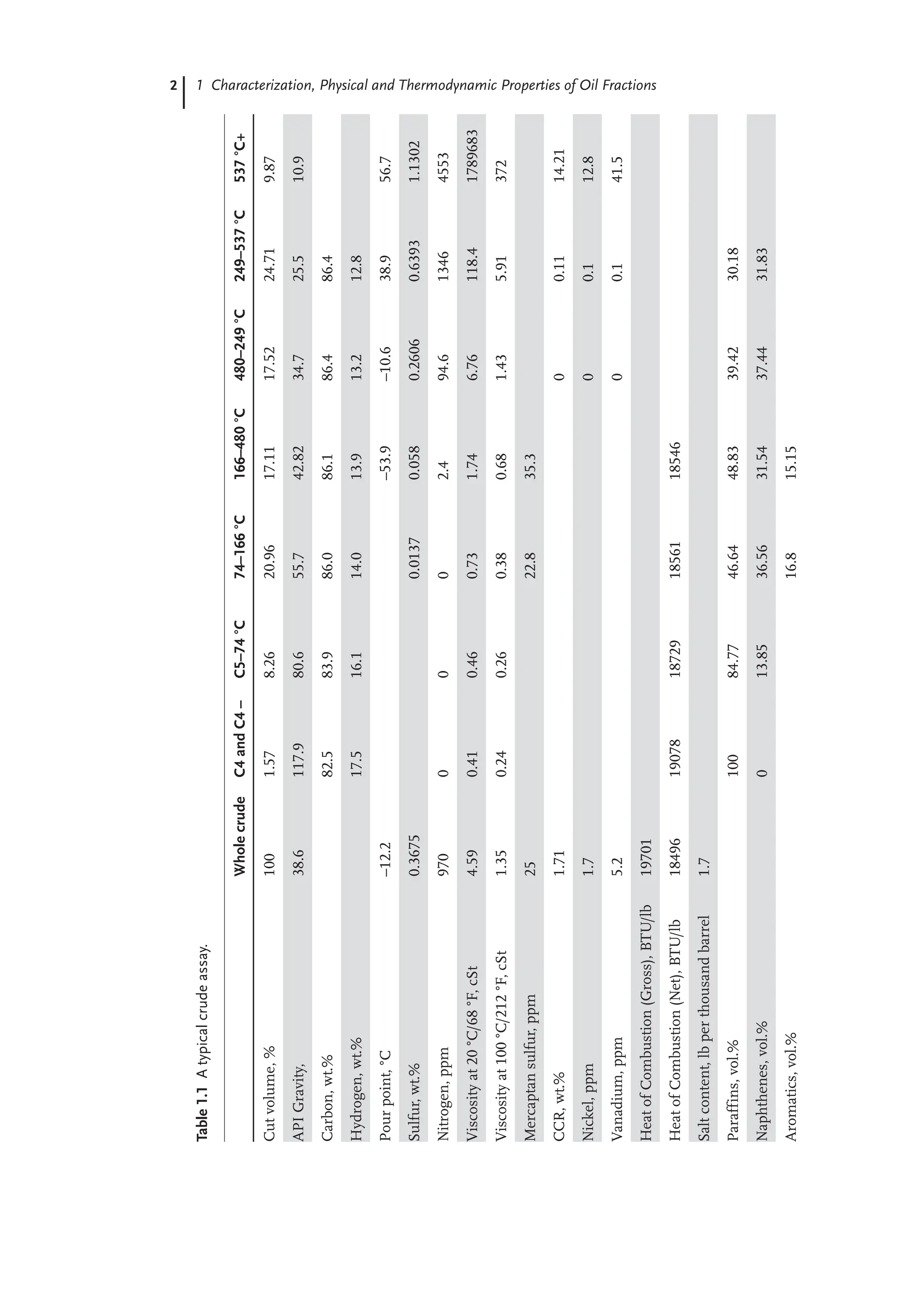
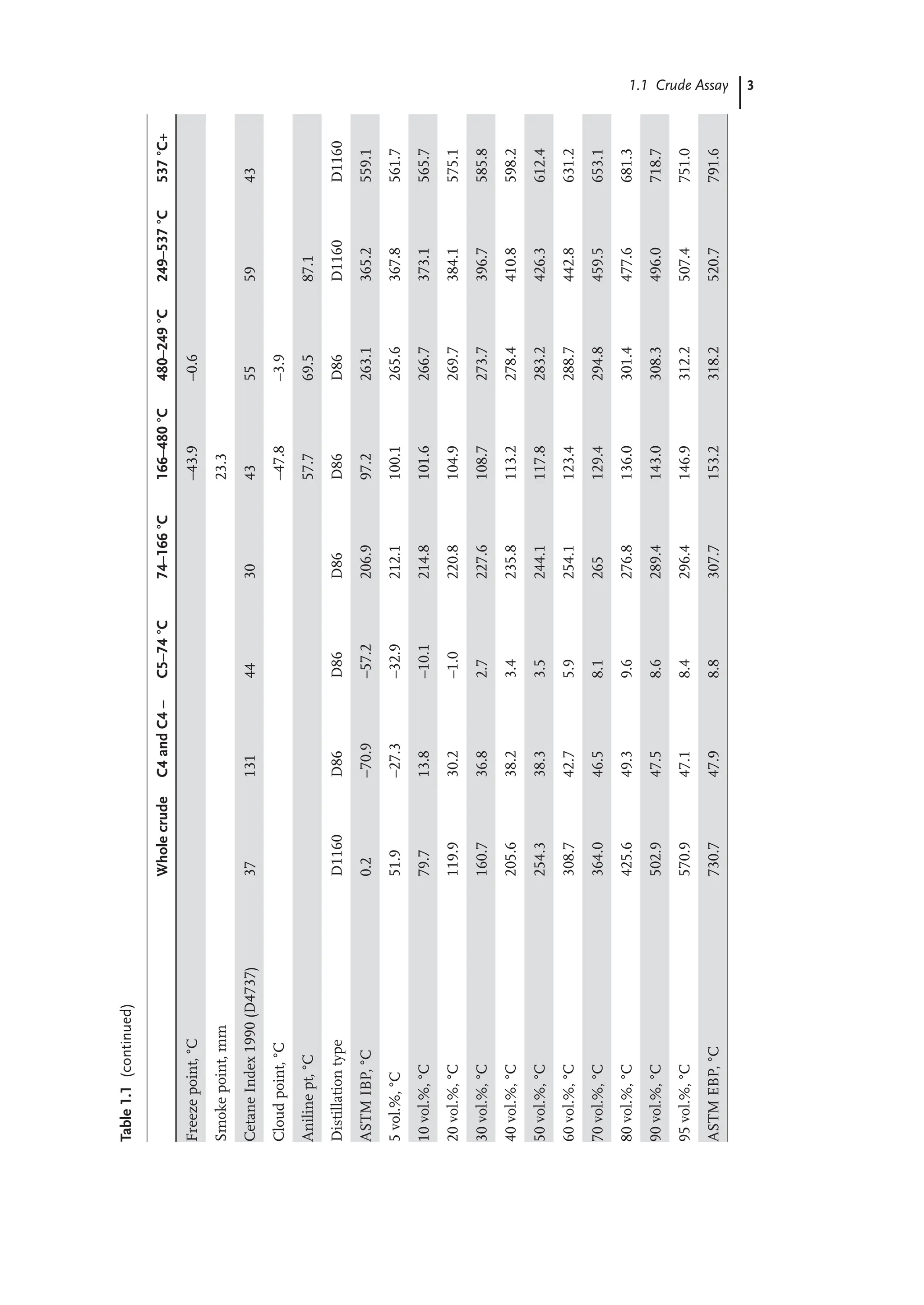
![4 1 Characterization, Physical and Thermodynamic Properties of Oil Fractions
A typical crude assay includes two types of information for an oil sample:
(1) bulk properties; and (2) fractional properties. Table 1.1 gives examples of both
properties of a crude assay. For design and modeling purposes, it is always the
best practice to have process data obtained in the same period as assay data, since
the properties and composition of crude change over time as it is produced from
a given well. Kaes [1] suggests that assay data should not be two years older than
the process data used to build process simulation. We explain both bulk and
fractional properties in the following subsections.
1.1.1
Bulk Properties
Bulk properties include specific gravity, sulfur content, nitrogen content, metal
(Ni, V, Fe etc.) content, asphaltene content, C/H ratio, pour point, flash point,
freeze point, smoke point, aniline point, cloud point,viscosity, carbon residue,
light hydrocarbon yields (C1–C4), acid number, refractive index and boiling point
curve. We generally use the API (American Petroleum Institute) gravity to specify
the specific gravity (SG) of the crude oil as API = (141.5/SG) – 131.5. SG is the
specific gravity defined as the ratio of the density of the crude oil to the density
of water both at 15.6 °C (60 °F). The API gravity varies from less than 10 for very
heavy crudes, to between 10 and 30 for heavy crudes, to between 30 and 40 for
medium crudes, and to above 40 for light crudes.
The sulfur content is expressed as a percentage of sulfur by weight, and varies
from less than 0.1% to greater than 5%. Crude oils with less than 1 wt.% sulfur
are called low-sulfur or sweet crude, and those with more than 1 wt.% sulfur are
called high-sulfur or sour crude. Sulfur-containing constituents of the crude oil
include simple mercaptans (also known as thiols), sulfides, and polycyclic sulfides.
Mercaptan sulfur is simply an alkyl chain (R–) with –SH group attached to it at the
end. The simplest form of R–SH is methyl mercaptan, CH3SH.
The pour point is a measure of how easy or difficult to pump the crude oil,
especially in cold weather. Specifically, the pour point is the lowest temperature
at which a crude oil will flow or pour when it is chilled without disturbance at a
controlled rate. The pour point of the whole crude or oil fractions boiling above
232 °C (450 °F) is determined by the standard test ASTM D97.
The flash point of a liquid hydrocarbon or an oil fraction indicates its fire and
explosion potential, and it is the lowest temperature at which sufficient vapor is
produced above the liquid to form a mixture with air that a spontaneous ignition
can occur if a spark is present. One of the standard ASTM test methods for the
flash point is D3278.
The freeze point is the temperature at which the hydrocarbon liquid solidifies
at atmospheric pressure. It’s an important property for kerosene and jet fuels,
because of the very low temperatures encountered at high altitudes in jet planes.
One of the standard test methods for the freeze point is ASTM D4790.
The smoke point refers to the height of a smokeless flame of fuel in milli-
meters beyond which smoking takes places. It reflects the burning quality of](https://image.slidesharecdn.com/2028732-250525235121-79b0e70b/75/Refinery-Engineering-Integrated-Process-Modeling-And-Optimization-Aifu-Chang-30-2048.jpg)
![5
1.1 Crude Assay
kerosene and jet fuels, and is determined by the standard testing method ASTM
D1322.
The aniline point represents the minimum temperature for complete miscibility
of equal volumes of aniline and petroleum oil. It’s an important property of diesel
fuels, and is measured by ASTM D611.
The cloud point refers to the temperature at which solidifiable components
(waxes) present in the oil sample begin to crystallize or separate from solution
under a method of prescribed chilling. It’s an important specification of middle
distillate fuels, as determined by ASTM D2500.
The Conradson carbon residue (CCR) results from ASTM test D189. It measures
the coke-forming tendencies of oil. It is determined by destructive distillation of
a sample to elemental carbon (coke residue), in the absence of air, expressed as
the weight percentage of the original sample. A related measure of the carbon
residue is called Ramsbottom carbon residue. A crude oil with a high CCR has a
low value as a refinery feedstock.
The acid number results from ASTM test method D3339-11 that determines the
organic acidity of a refinery stream.
The refractive index represents the ratio of the velocity of light in a vacuum to
that in the oil. It is determined by ASTM D1218.
The gross heat of combustion or high heating value (HHV) is the amount of heat
produced by the complete combustion of a unit quantity of fuel. We obtain the
gross heat of combustion by cooling down all products of the combustion to the
temperature before the combustion, and by condensing all the water vapor formed
during combustion.
The net heat of combustion or lower heating value (LHV) is obtained by subtract-
ing the latent heat of vaporization of the water vapor formed by the combustion
from the gross heat of combustion or higher heating value.
The true boiling point (TBP) distillation [1] of a crude oil or petroleum fractions
results from using the U. S. Bureau of Mines Hempel method and the ASTM
D-285 test procedure. Neither of these methods specifies the number of theoretical
stages or the molar reflux ratio used in the distillation. Consequently, there is a
trend toward applying a 15:5 distillation according to ASTM D2892, instead of the
TBP. The 15:5 distillation uses 15 theoretical stages and a molar reflux ratio of 5.
A key result from a distillation test is the boiling point curve, that is, the boiling
point of the oil fraction versus the fraction of oil vaporized. The initial boiling
point (IBP) is defined as the temperature at which the first drop of liquid leaves
the condenser tube of the distillation apparatus. The final boiling point or the end
point (EP) is the highest temperature recorded in the test.
Additionally, oil fractions tend to decompose or crack at a temperature of
approximately 650 °F (344 °C) at one atmosphere. Thus, the pressure of TBP
distillation is gradually reduced to as low as 40 mmHg, as this temperature is
approached to avoid cracking the sample and distorting measurements of true
components in the oil.
The TBP distillation typically takes much time and labor. In practice, we carry
out the distillation test of oil fractions using other less costly ASTM methods and](https://image.slidesharecdn.com/2028732-250525235121-79b0e70b/75/Refinery-Engineering-Integrated-Process-Modeling-And-Optimization-Aifu-Chang-31-2048.jpg)
![6 1 Characterization, Physical and Thermodynamic Properties of Oil Fractions
convert the resulting boiling point curve to TBP curve using correlations, as given
in the API Technical Data Book-Petroleum Refining [2]. We have implemented
these correlations in an Excel spreadsheet of the Interconversion of boiling
point curves from typical ASTM distillation methods in a hands-on workshop
in Section 1.3.
The ASTM D86 distillation of an oil fraction takes place at laboratory room
temperature and pressure. Note that the D86 distillation will end below an
approximate temperature of 650 °F (344 °C), at which petroleum oils begin to
crack at one atmospheric pressure.
The ASTM D1160 distillation of an oil fraction is applicable to high-boiling oil
samples (e.g. heavy heating oil, cracker gas oil feed, residual oil, etc.) for which
there is significant cracking at atmospheric pressures. The sample is distilled at a
reduced pressure, typically at 10 mmHg, to inhibit cracking. In fact, at 10 mmHg,
we can distill an oil fraction up to temperatures of 950 to 1000 °F (510 to 538 °C),
as reported on a 760-mmHg basis. The reduced pressure used for D1160 distil-
lation produces a separation of components that is more ideal than that for D86
distillation.
The ASTM D2887 distillation of an oil fraction is a popular chromatographic
procedure to “simulate” or predict the boiling point curve of an oil fraction. We
determine the boiling point distribution by injecting the oil sample into a gas
chromatograph that separates the hydrocarbons in a boiling-point order. We then
relate the retention time inside the chromatograph to the boiling point through
a calibration curve.
1.1.2
Fractional Properties
Bulk properties provide a quick understanding of the type of the oil sample such as
sweet and sour, light and heavy, etc. However, refineries require fractional properties
of the oil sample that reflects the property and composition for specific boiling-
point range to properly refine it into different end products such as gasoline, diesel
and raw materials for chemical process. Fractional properties usually contains
paraffins, naphthenes and aromatics (PNA) contents, sulfur content, nitrogen
content for each boiling-point range, octane number for gasoline, freezing point,
cetane index and smoke point for kerosene and diesel fuels.
The octane number is a measure of the knocking characteristics of a fuel in a
laboratory gasoline engine according to ASTM D2700 [1]. We determine the octane
number of a fuel by measuring its knocking value compared to the knocking
of a mixture of n-heptane and isooctane or 2-2-4-trimethylpentane (224TMP).
By definition, we assign an octane number of 0 to pure heptane and of 100 to
224TMP. Therefore, a mixture of 30% heptanes and 70% isooctane has an octane
number of 70.
There are two specific octane numbers in use. The motor octane number (MON)
reflects the engine performance at highway conditions with high speeds (900 rpm),
while the research octane number (RON) corresponds to the low-speed city driving](https://image.slidesharecdn.com/2028732-250525235121-79b0e70b/75/Refinery-Engineering-Integrated-Process-Modeling-And-Optimization-Aifu-Chang-32-2048.jpg)
![7
1.1 Crude Assay
(600 rpm). RON is typically higher than MON because of engine test efficiencies.
The posted octane number is an average of MON and RON.
The cetane number measures the ease for self-ignition of a diesel fuel sample
and is essentially an opposite of the octane number. It represents the percentage
of pure cetane (n-hexadecane) in a blend of cetane and alpha methyl-naphthalene
that matches the ignition quality of a diesel fuel sample. This quality is important
for middle distillate fuels.
The cetane index is a number calculated from the average boiling point and
gravity of a petroleum fraction in the diesel fuel boiling range, which estimates
the cetane number of the fraction according to ASTM D976 (see, for example,
http://www.epa.gov/nvfel/testproc/121.pdf).
1.1.3
Interconversion of Distillation Curves
While building a refining process simulation, distillation curve of the oil sample
is the most confusing information among assay data since there are different
methods used to obtain volatility characteristics of an oil sample. The most
widely used tests of distillation curve are ASTM D86, ASTM D1160 (atmospheric
distillation), ASTM D1160 (vaccum distillation), ASTM D2887 (chromatographic
simulation) and true boiling point (TBP). API Technical Databook [35] presents
the characteristics of each test and gives the correlations to perform interconver-
Figure 1.1 Conversion spreadsheet for distillation curves.](https://image.slidesharecdn.com/2028732-250525235121-79b0e70b/75/Refinery-Engineering-Integrated-Process-Modeling-And-Optimization-Aifu-Chang-33-2048.jpg)
![8 1 Characterization, Physical and Thermodynamic Properties of Oil Fractions
sion among these ASTM distillation types. Most commercial process simulators
include the capability to convert one type of distillation curve to the other. We
develop a MS Excel spreadsheet which automates the API conversion between
any two of the ASTM distillation types (see Figure 1.1). Section 1.3 presents a
hands-on workshop for this interconversion of distillation-curve data.
1.2
Pseudocomponent Generation Based on Boiling-Point Ranges
To simulate refining processes, the first task is to construct a pseudocomponent
scheme to characterize the feedstock. Data requirement and definition of the
pseudocomponents depend on the type of the refining process to be modeled.
There are different concerns to be addressed when building pseudocomponents
for fractionation and reaction units. The pseudocomponents for fractionation units
have to accurately characterize volatilities of the hydrocarbons in the feedstock
in order to calculate vapor-liquid-equilibrium in distillation columns. Therefore,
refiners use pseudocomponents based on boiling-point ranges to represent the
feedstock and model fractionation units. For modeling of reaction units, refiners
partition the hydrocarbons into multiple lumps (or model compounds) based on
molecular structure or/and boiling-point ranges, and assume the hydrocarbons of
each lump to have an identical reactivity in order to develop the reaction kinetics
for reaction units. This section deals with pseudocomponent generation based
on boiling-point ranges for fractionation units. Chapters 4 to 6 will present the
pseudocomponent schemes for the three major reaction units in modern refinery
– fluid catalytic cracking (FCC), catalytic reformer and catalytic hydrocracker.
Most commercial process simulators include the capability to generate
pseudocomponents based on boiling-point ranges representing the oil fractions.
Workshop 1.4 will demonstrate how to use Aspen HYSYS to generate pseudo-
components based on boiling-point ranges for a given oil fraction with required
analysis data. Conventionally, there are four steps to develop pseudocomponents
based on boiling-point ranges to represent petroleum fraction:
1. Convert ASTM D86/ASTM D1160/ASTMD2887 into TBP curve if TBP curve
is not available:
– We develop a spreadsheet which allows interconversion between different
ASTM distillation types based on the correlations from [2] (see Figure 1.1);
2. Cut the entire boiling range into a number of cut-point ranges which are used
to define pseudocomponents (see Figure 1.2):
– The determination of number of cuts is arbitrary. Table 1.2 lists the typical
boiling-point ranges for pseudocomponents in commercial simulators.
3. Estimate the density distribution of pseudocomponents if only the bulk density
is available:](https://image.slidesharecdn.com/2028732-250525235121-79b0e70b/75/Refinery-Engineering-Integrated-Process-Modeling-And-Optimization-Aifu-Chang-34-2048.jpg)
![9
1.2 Pseudocomponent Generation Based on Boiling-Point Ranges
– Assume the UOP or Watson-Murphy “characterization factor” or K factor to
be constant throughout the entire boiling range and calculate mean-average
boiling point (MeABP). Dissimiliar to weight-average boiling point (WABP),
MeABP is defined as the average of molal-average boiling point (MABP) and
cubic-average boiling point (CABP). The following equations define these
four boiling-point indicators:
Figure 1.2 Relationship between pseudocomponent properties and the TBP curve
(redraw from [1]).
Table 1.2 Typical boiling-point ranges for pseudocomponents in commercial process simulators.
Boiling-point Range Suggested Number of Pseudocomponents
IBP to 800 °F (425 °C) 30
800 °F to 1200 °F (650 °C) 10
1200 °F to 1650 °F (900 °C) 8](https://image.slidesharecdn.com/2028732-250525235121-79b0e70b/75/Refinery-Engineering-Integrated-Process-Modeling-And-Optimization-Aifu-Chang-35-2048.jpg)
![10 1 Characterization, Physical and Thermodynamic Properties of Oil Fractions
i bi
WABP
n
i
x T
1
(1.1)
i bi
MABP
n
i
x T
1
(1.2)
/
i bi
CABP
n
i
x T
3
1 3
1
(1.3)
MABP CABP
MeABP
2
(1.4)
where Tbi indicates boiling point of component i and xi in Equation (1.1)
to (1.3) indicate weight fraction, molar fraction and volume fraction of
component i, respectively. Here, we create a spreadsheet tool (see Figure 1.3)
to perform the iteration of estimating MeABP based on the methods
presented by Bollas et al. [3]
.
avg avg
MeABP SG
K
0 333
(1.5)
where Kavg is Watson K factor and SGavg is the bulk specific gravity
60 °F/60 °F
– Calculate the density distribution of the entire boiling range:
.
i i,b avg
SG T K
0 333
(1.6)
where SGi is the specific gravity 60 °F/60 °F of pseudocomponent i and Ti,b
is the normal boiling point of pseudocomponent i.
4. Estimate the molecular weight distribution of the entire boiling range if not
available and required properties for modeling purpose (see Section 1.3 for
details).
Lacking the analysis data of high boiling-point range (> 570 °C) is a common
problem while building pseudocomponents based on boiling-point ranges.
Therefore, we need to extrapolate the incomplete distillation curve in order to
cover the entire boiling-point range. Least-squares and probability-distribution
functions are most widely used to perform the extrapolation of distillation curve
in most commercial process simulators. Sanchez et al. [5] present a comprehen-
sive review of using probability-distribution functions to fit distillation curves
of petroleum fractions. They conclude that the cumulative beta function (with
four parameters) can represent a wide range of petroleum products. The beta
cumulative density function is defined as:
, , , ,
x B
A
x A B x
f x A B
B A B A B A
1 1
1 Γ
Γ Γ
(1.7)](https://image.slidesharecdn.com/2028732-250525235121-79b0e70b/75/Refinery-Engineering-Integrated-Process-Modeling-And-Optimization-Aifu-Chang-36-2048.jpg)
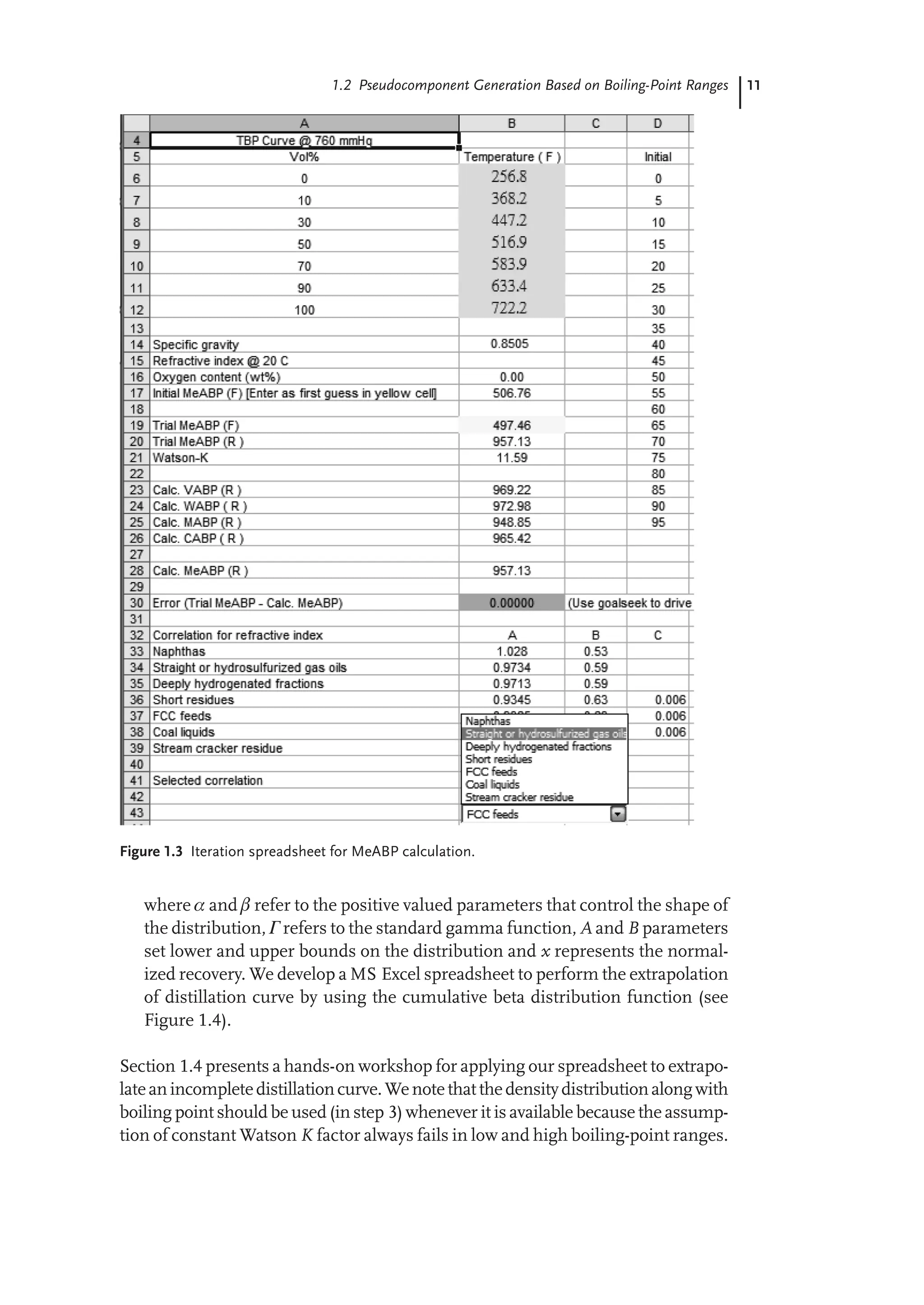
![12 1 Characterization, Physical and Thermodynamic Properties of Oil Fractions
Figure 1.5 compares the pseudocomponents generated from constant Watson
K factor and from density distribution. The pseudocomponents generated from
constant Watson K factor shows significant deviations from assay data on esti-
mating the densities of pseudocomponents, particularly in both light and heavy
ends of the distillation curve. On the other hand, using density distribution is able
to provide a good estimation of the densities of pseudocomponents. Estimating
the densities of pseudocomponents is the most important part when developing
pseudocomponents because density is required for most of the physical property
estimations.
Figure 1.5 Comparison of the pseudocomponents generated from constant Watson K factor
and density distribution (data obtained from [1]).
Figure 1.4 Spreadsheet for extrapolating distillation curve.](https://image.slidesharecdn.com/2028732-250525235121-79b0e70b/75/Refinery-Engineering-Integrated-Process-Modeling-And-Optimization-Aifu-Chang-38-2048.jpg)