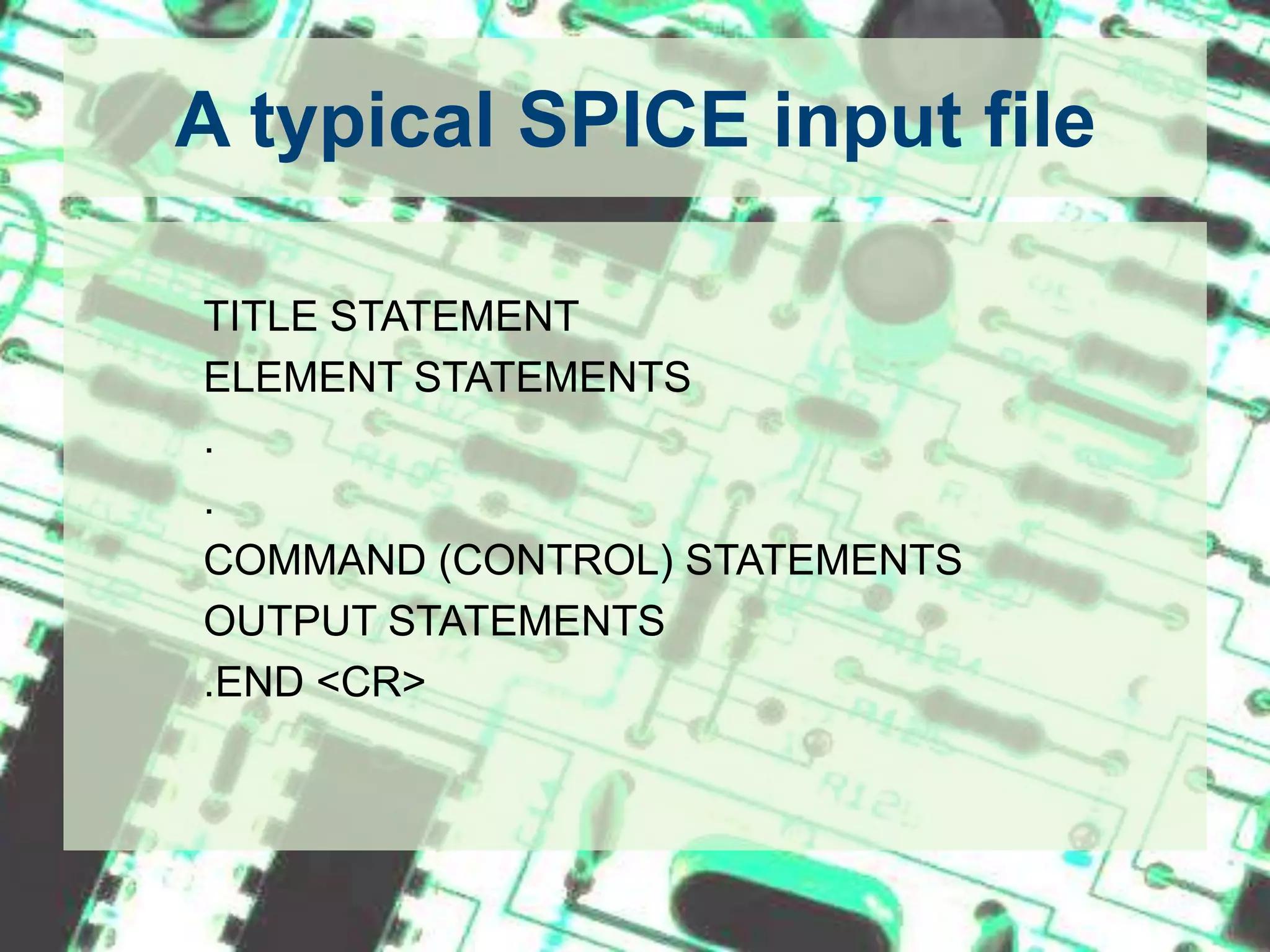
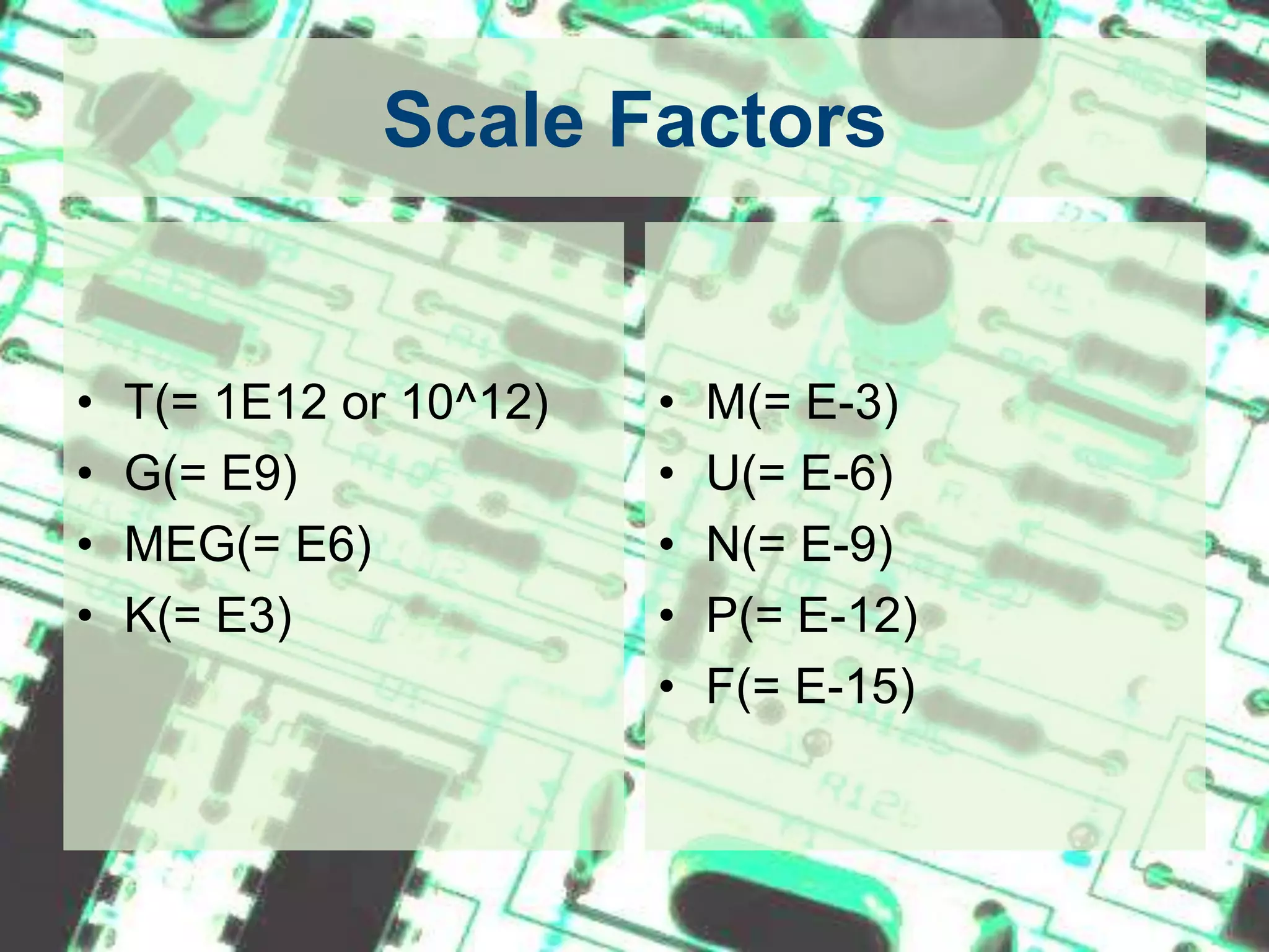
PSPICE TutorialAnkit G DoshiThe University of Texas at ArlingtonJuly 22nd 2010
IntroductionSPICE - Simulation Program with Integrated Circuits EmphasisDeveloped by the University of California, Berkeley in 1960sStill widely used simulator for analog circuit simulations in industry and R&D centers.Types of input fileNetlist - Type in the circuit using simple text.  (*.cir)Schematics - Draw circuit using drag and drop parts. (*.sch)
Where to get the softwarehttp://www.cadence.com/products/orcad/pages/downloads.aspx
How to type in the given circuitAny SPICE input file is made up of 3 sections1. Data statements - description of the components and the interconnections.2. Control Statements - tells SPICE what type of analysis to perform on the circuit.3. Output Statements - specifies what outputs are to be printed or plotted.Although these statements may appear in any order, it is recommended that they be given in the above sequence.
How to type in the given circuitTwo other statements are required: the title statement and the end statement. The title statement is the first line and can contain any informationThe end statement is always .END. This statement must be a line be itself, followed by a carriage return!In addition, you can insert comment statements, which must begin with an asterisk (*) and are ignored by SPICE. If one wants to continue a statement to the next line, one uses a "+" sign (continuation sign) at the beginning of the next line.Numbers can be integers, or floating points.SPICE is not case sensitive. (i.e. Vbus, VBUS, vbus all are same).
A typical SPICE input file		TITLE STATEMENT		ELEMENT STATEMENTS		.		.		COMMAND (CONTROL) STATEMENTS		OUTPUT STATEMENTS		.END <CR>
Scale FactorsT(= 1E12 or 10^12)G(= E9)MEG(= E6)K(= E3)M(= E-3)U(= E-6)N(= E-9)P(= E-12)F(= E-15)
1. Data StatementsTo Specify the Circuit Components and Topology
Independent DC SourcesVoltage source: Vname N1 N2 Type Value Current source: Iname   N1 N2 Type Value N1 is the positive terminal nodeN2 is the negative terminal nodeType can be DC, AC or TRAN, depending on the type of analysisValue gives the value of the sourceThe name of a voltage and current source must start with V and I, respectively.Examples:Vin 2 0 DC 10Is 3 4 DC 1.5
Dependent SourcesVoltage controlled voltage source: Ename N1 N2 NC1 NC2 ValueVoltage controlled current source: Gname N1 N2 NC1 NC2 ValueCurrent controlled voltage source: Hname N1 N2 Vcontrol ValueCurrent controlled current source: Fname N1 N2 Vcontrol ValueN1 and N2 are the positive and negative terminals of the dependent source, respectively.NC1 and NC2 are the positive and negative terminals of the controlling voltage source, respectively.Vcontrol is the zero value voltage source used to measure the controlling current (the positive current flows into the positive terminal of the controlling voltage source!).Example:Ebar    17   8   42   18    24.0		(VCVS)Glab    23  17    8     3    2.5		(VCIS)Hvx     20  12  Vhx       50.0		(CCVS)Vhx     80  76  DC        0V ; controls HvxFtrn     81   19   Vctl         50.0		(CCCS)Vclt     23   12   DC           0V ; controls Ftrn
Resistors, Capacitors and InductorsResistor: RnameN1 N2 ValueCapacitor: Cname N1 N2 Value <IC>Inductor:   Lname N1 N2 Value <IC>N1 is the positive node.N2 is the negative node.IC is the initial condition (DC voltage or current).The symbol < > means that the field is optional. If not specified, it is assumed to be zero. In case of an inductor, the current flows from N1 to N2.Example:Rin 3 4 100kCc  7 8  20f 5L3  2 0  6.25m 1m
Sinusoidal SourcesSinusoidal Voltage Source:Vname N1 N2 SIN(VO VA FREQ TD THETA PHASE) Vname = VO + VA exp[-THETA.(t - TD)] sin[2pi.f (t - TD) + (Phase/360)]VO - offset voltage in volt.VA - amplitude in volt.f = FREQ - the frequency in herz.TD - delay in secondsTHETA - damping factor per secondPhase - phase in degrees If TD, THETA and PHASE are not specified, it is assumed to be zero.    Example:VG   1 2  SIN(5 10 50 0.2 0.1)VG2 3 4  SIN(0 10 50)To generate a cosine function, you can make use of the phase relationship between the sinusoid and cosine. Here is an example of an undelayed cosine with an amplitude of 5V and frequency of 50 Hz. Vcos 1 2 SIN(0 5 50 0 0 90)
Piecewise Linear Sources (PWL)Vname N1 N2 PWL(T1 V1 T2 V2 T3 V3 ...)in which (Ti Vi) specifies the value Vi of the source at time Ti Example:Vgpwl 1 2 PWL(0 0 10U 5 100U 5 110U 0)
TransformersSPICE has no model for an ideal transformer. An ideal transformer is simulated using two inductors mutual inducting on each other such that the transformer ratio N1/N2 = sqrt(L1/L2). Make the coupling factor K close to one (ex. K=0.99999). The secondary circuit needs a DC connection to ground. This can be accomplished by adding a large resistor to ground or giving the primary and secondary circuits a common node.
Transformers (Cont.)	Example transformer	VIN 2 0 SIN(0 170 60 0 0)	* This defines a sinusoid of 170 *amplitude and 60 Hz. 	RS 2 1 10	L1 1 0 2000	L2 3 0 20	K L1 L2 0.99999	.TRAN 0.2M 25M	.PLOT TRAN V(2)	.PLOT TRAN V(3)	.END
SubcircuitsA subcircuit allows you to define a collection of elements as a subcircuit (e.g. an operational amplifier) and to insert this description into the overall circuit (as you would do for any other element).It is a kind of function or subroutine in C.Defining a subcircuit A subcircuit is defined by a .SUBCKT control statement, followed by the circuit description as follows: 	   	.SUBCKT SUBNAME N1 N2 N3 ...		Element statements		Element statements		Element statements		ENDS SUBNAMEin which SUBNAME is the subcircuit name and N1, N2, N3 are the external nodes of the subcircuit. The external nodes cannot be 0. The node numbers used inside the subcircuit are strictly local, except for node 0 which is always global.
Subcircuits (Cont.)	.SUBCKT OpAmpp_inn_in com out	Ex   int   com   p_inn_in   1e5Rip_inn_in  500k	Ro   int   out   50.0	.ENDS
Subcircuits (Cont.)Using a subcircuit The element statement for a subcircuit is similar to any other element. The format is as follows:Xname N1 N2 N3 ... SUBNAMEWhere Xname refers to the element (subcircuit) being usedN1, N2, N3 are the nodes to which the external nodes of the subcircuit are being connectedSUBNAME is the name of the subcircuit being used. 
Subcircuits (Cont.)Subcircuit Example - Inverting OpAmp	.SUBCKT OpAmpp_inn_in com out	Ex   int   com   p_inn_in   1e5Rip_inn_in  500k	Ro   int   out   50.0	.ENDS	Vg   1     0     DC      50mVRg   1     2     5kRf   2     3     50k	RL   3     0     20k	X1   0     2     0      3    OpAmp	.END
Semiconductor DevicesMost of the elements that have been described above require only a few parameters to specify its electrical characteristics. However, the models for semiconductor devices require many parameter values. A set of device model parameters is defined in a separate .MODEL statement and assigned a unique name. Thus a semiconductor device is specified by two command lines: an element and model statement.Element Line:		ElementName N+ N- MODNameModel Statement:   	.MODEL MODName Type (parameter values)MODName is the name of the model for the device. Type refers to the type of device and can be any of the following: D: DiodeNPN: npn bipolar transistorPNP: pnp bipolar transistorNMOS: nmos transistorPMOS: pmos transistorNJF: N-channel JFET modelPJF: P-channel JFET model
Semiconductor Devices (Cont.)DiodeElement line: Dname N+ N- MODNameModel Statement: .MODEL MODName D (IS= N= Rs= CJO= Tt= BV= IBV=)Example:D1		5    3 D1N4148.model D1N4148 D (IS=0.1PA, RS=16 CJO=2PF TT=12N BV=100 IBV=0.1PA)
Semiconductor Devices (Cont.)BJTElement Line:       Qname C B E BJT_modelNameModel statement: .MODEL BJT_modName NPN (BF=val IS=val VAF=val)Example:Q3    4   2   0   Q2N2222A.model Q2N2222A NPN (IS=14.34F XTI=3 EG=1.11 VAF= 74.03 BF=255.9             + NE=1.307 ISE=14.34F IKF=.2847 XTB=1.5 BR=6.092 NC=2 ISC=0 IKR=0       + RC=1 CJC=7.306P MJC=.3416 VJC=.75 FC=.5 CJE=22.01P MJE=.377          + VJE=.75 TR=46.91N TF=411.1P ITF=.6 VTF=1.7 XTF=3 RB=10)
Semiconductor Devices (Cont.)MOSFETElement Line: 	Mname ND NG NS <NB> ModName L= W= Model statement:	.MODEL ModName NMOS (KP= VT0= lambda= gamma=)Example:M5    4   2   0	CMOSN.model CMOSN NMOS (LEVEL=3 PHI=0.600000 TOX=2.1200E-08 XJ=0.200000U   +TPG=1 VTO=0.7860 DELTA=6.9670E-01 LD=1.6470E-07 KP=9.6379E-05+UO=591.7 THETA=8.1220E-02 RSH=8.5450E+01 GAMMA=0.5863+NSUB=2.7470E+16 NFS=1.98E+12 VMAX=1.7330E+05 ETA=4.3680E-02+KAPPA=1.3960E-01 CGDO=4.0241E-10 CGSO=4.0241E-10+CGBO=3.6144E-10 CJ=3.8541E-04 MJ=1.1854 CJSW=1.3940E-10+MJSW=0.125195 PB=0.800000)
2. Control StatementsTells SPICE what type of analysis to perform on the circuit.
.OP StatementThis statement instructs Spice to compute the DC operating points:  voltage at the nodescurrent in each voltage sourceoperating point for each element
.DC StatementThis statement allows you to increment (sweep) an independent source over a certain range with a specified step. The format is as follows: .DC SRCname START STOP STEPin which SRC name is the name of the source you want to vary;START and STOP are the starting and ending value, respectively; and STEP is the size of the increment. Example: .DC V1 0 20 2
.AC StatementThis statement is used to specify the frequency (AC) analysis. The format is as follows: 	.AC LIN NP FSTART FSTOP	.AC DEC ND FSTART FSTOP	.AC OCT NO FSTART FSTOPIn which LIN stands for a linear frequency variation, DEC and OCT for a decade and octave variation respectively. NP stands for the number of points and ND and NO for the number of frequency points per decade and octave. FSTART and FSTOP are the start and stopping frequencies in Hertz Example: .AC DEC 10 1000 1E6.TRAN StatementThis statement specifies the time interval over which the transient analysis takes place, and the time increments. The format is as follows: .TRAN TSTEP TSTOP <TSTART <TMAX>> <UIC> TSTEP is the printing increment.TSTOP is the final timeTSTART is the starting time (if omitted, TSTART is assumed to be zero)TMAX is the maximum step size.UIC stands for Use Initial Condition and instructs PSpice not to do the quiescent operating point before beginning the transient analysis. If UIC is specified, PSpice will use the initial conditions specified in the element statements.
Other Control Statements.NOISE	- For NOISE Analysis.DISTO	- For DISTORTION Analysis.FOUR	- For FOURIER Analysis		etc.
3. Output StatementsThese statements will instruct PSpice what output to generate.If you do not specify an output statement, PSpice will always calculate the DC operating points.
.PRINT StatementIt generates is a table of data points.Format: .PRINT TYPE OV1 OV2 OV3 ...in which TYPE specifies the type of analysis to be printed or plotted and can be: DC, TRAN, ACExample: .PRINT TRAN V(3,1) I(Vmeas)
.PROBE StatementIt generates is a plot.Format: .PROBEWhen using .PROBE statement as output, after successfully simulating the netlist a blank graph is generated. User has to manually insert traces of interest to see the graph.
Example 1
Example 1 (Cont.)EXAMPLE Pspice		TITLE LineVIN 1 0 DC 10				F1 0 3 VMEAS 0.5		   	   |VMEAS 4 0 DC 0		   	   |	R1 1 2 1K		   	  	   |R2 2 3 10K		   	   	   |DATAR3 1 3 15K		   	   	   |R4 2 4 40K		   	   	   |R5 3 0 50K				.OP					.TF V(3,0) VIN			   	   |CONTROL.DC VIN 0 20 2				.PRINT DC V(1,2) V(2,4) I(VMEAS)	 OUTPUT.PROBE				  	 OUTPUT.END					 END Statement
Example 2
Example 2 (Cont.)		Full wave rectifier power supply		Vin       5  0	SIN(0 170 60)		* Transformer		L1        6   0     330		L2        1   0     3		K L1 L2 0.99999		RS       5   6     0.1		*Bridge		D1	2	1	diode		D2	2	0	diode		D3	1	3	diode			D4	0	3	diode		R	3	4	98		C	3	2	425u		RL	4	2	450		D	2	4	mod1		.model diode D (IS=0.1PA, RS=16 CJO=2PF TT=12N BV=100 IBV=0.1PA)		.model mod1 D (IS=0.1PA, RS=16 CJO=2PF TT=12N BV=10 IBV=0.1PA)		.TRAN 0.2m 10		.PROBE		.END
ReferencesSPICE – Brief Tutorial, By Jan Van derSpigel from University of PennsylvaniaSPICE, A Guide to Circuit Simulation and Analysis Using PSpice, 3rd Ed. By P. Tuinenga, Prentice Hall, Upper Saddle River, NJ, 1995PSPICE Tutorial, By Dr. Dillon from The University of Texas at Arlington (http://www.uta.edu/ee/hw/pspice/)
Questions
THANK YOU
PSpice Tutorial

PSpice Tutorial

  • 1.
    PSPICE TutorialAnkit GDoshiThe University of Texas at ArlingtonJuly 22nd 2010
  • 2.
    IntroductionSPICE - SimulationProgram with Integrated Circuits EmphasisDeveloped by the University of California, Berkeley in 1960sStill widely used simulator for analog circuit simulations in industry and R&D centers.Types of input fileNetlist - Type in the circuit using simple text. (*.cir)Schematics - Draw circuit using drag and drop parts. (*.sch)
  • 3.
    Where to getthe softwarehttp://www.cadence.com/products/orcad/pages/downloads.aspx
  • 4.
    How to typein the given circuitAny SPICE input file is made up of 3 sections1. Data statements - description of the components and the interconnections.2. Control Statements - tells SPICE what type of analysis to perform on the circuit.3. Output Statements - specifies what outputs are to be printed or plotted.Although these statements may appear in any order, it is recommended that they be given in the above sequence.
  • 5.
    How to typein the given circuitTwo other statements are required: the title statement and the end statement. The title statement is the first line and can contain any informationThe end statement is always .END. This statement must be a line be itself, followed by a carriage return!In addition, you can insert comment statements, which must begin with an asterisk (*) and are ignored by SPICE. If one wants to continue a statement to the next line, one uses a "+" sign (continuation sign) at the beginning of the next line.Numbers can be integers, or floating points.SPICE is not case sensitive. (i.e. Vbus, VBUS, vbus all are same).
  • 6.
    A typical SPICEinput file TITLE STATEMENT ELEMENT STATEMENTS . . COMMAND (CONTROL) STATEMENTS OUTPUT STATEMENTS .END <CR>
  • 7.
    Scale FactorsT(= 1E12or 10^12)G(= E9)MEG(= E6)K(= E3)M(= E-3)U(= E-6)N(= E-9)P(= E-12)F(= E-15)
  • 8.
    1. Data StatementsToSpecify the Circuit Components and Topology
  • 9.
    Independent DC SourcesVoltagesource: Vname N1 N2 Type Value Current source: Iname N1 N2 Type Value N1 is the positive terminal nodeN2 is the negative terminal nodeType can be DC, AC or TRAN, depending on the type of analysisValue gives the value of the sourceThe name of a voltage and current source must start with V and I, respectively.Examples:Vin 2 0 DC 10Is 3 4 DC 1.5
  • 10.
    Dependent SourcesVoltage controlledvoltage source: Ename N1 N2 NC1 NC2 ValueVoltage controlled current source: Gname N1 N2 NC1 NC2 ValueCurrent controlled voltage source: Hname N1 N2 Vcontrol ValueCurrent controlled current source: Fname N1 N2 Vcontrol ValueN1 and N2 are the positive and negative terminals of the dependent source, respectively.NC1 and NC2 are the positive and negative terminals of the controlling voltage source, respectively.Vcontrol is the zero value voltage source used to measure the controlling current (the positive current flows into the positive terminal of the controlling voltage source!).Example:Ebar 17 8 42 18 24.0 (VCVS)Glab  23  17    8     3    2.5 (VCIS)Hvx  20  12  Vhx       50.0 (CCVS)Vhx  80  76  DC        0V ; controls HvxFtrn   81   19   Vctl         50.0 (CCCS)Vclt   23   12   DC           0V ; controls Ftrn
  • 11.
    Resistors, Capacitors andInductorsResistor: RnameN1 N2 ValueCapacitor: Cname N1 N2 Value <IC>Inductor: Lname N1 N2 Value <IC>N1 is the positive node.N2 is the negative node.IC is the initial condition (DC voltage or current).The symbol < > means that the field is optional. If not specified, it is assumed to be zero. In case of an inductor, the current flows from N1 to N2.Example:Rin 3 4 100kCc 7 8 20f 5L3 2 0 6.25m 1m
  • 12.
    Sinusoidal SourcesSinusoidal VoltageSource:Vname N1 N2 SIN(VO VA FREQ TD THETA PHASE) Vname = VO + VA exp[-THETA.(t - TD)] sin[2pi.f (t - TD) + (Phase/360)]VO - offset voltage in volt.VA - amplitude in volt.f = FREQ - the frequency in herz.TD - delay in secondsTHETA - damping factor per secondPhase - phase in degrees If TD, THETA and PHASE are not specified, it is assumed to be zero.    Example:VG 1 2 SIN(5 10 50 0.2 0.1)VG2 3 4 SIN(0 10 50)To generate a cosine function, you can make use of the phase relationship between the sinusoid and cosine. Here is an example of an undelayed cosine with an amplitude of 5V and frequency of 50 Hz. Vcos 1 2 SIN(0 5 50 0 0 90)
  • 13.
    Piecewise Linear Sources(PWL)Vname N1 N2 PWL(T1 V1 T2 V2 T3 V3 ...)in which (Ti Vi) specifies the value Vi of the source at time Ti Example:Vgpwl 1 2 PWL(0 0 10U 5 100U 5 110U 0)
  • 14.
    TransformersSPICE has nomodel for an ideal transformer. An ideal transformer is simulated using two inductors mutual inducting on each other such that the transformer ratio N1/N2 = sqrt(L1/L2). Make the coupling factor K close to one (ex. K=0.99999). The secondary circuit needs a DC connection to ground. This can be accomplished by adding a large resistor to ground or giving the primary and secondary circuits a common node.
  • 15.
    Transformers (Cont.) Example transformer VIN2 0 SIN(0 170 60 0 0) * This defines a sinusoid of 170 *amplitude and 60 Hz. RS 2 1 10 L1 1 0 2000 L2 3 0 20 K L1 L2 0.99999 .TRAN 0.2M 25M .PLOT TRAN V(2) .PLOT TRAN V(3) .END
  • 16.
    SubcircuitsA subcircuit allowsyou to define a collection of elements as a subcircuit (e.g. an operational amplifier) and to insert this description into the overall circuit (as you would do for any other element).It is a kind of function or subroutine in C.Defining a subcircuit A subcircuit is defined by a .SUBCKT control statement, followed by the circuit description as follows:      .SUBCKT SUBNAME N1 N2 N3 ... Element statements Element statements Element statements ENDS SUBNAMEin which SUBNAME is the subcircuit name and N1, N2, N3 are the external nodes of the subcircuit. The external nodes cannot be 0. The node numbers used inside the subcircuit are strictly local, except for node 0 which is always global.
  • 17.
    Subcircuits (Cont.) .SUBCKT OpAmpp_inn_incom out Ex int com p_inn_in 1e5Rip_inn_in 500k Ro int out 50.0 .ENDS
  • 18.
    Subcircuits (Cont.)Using asubcircuit The element statement for a subcircuit is similar to any other element. The format is as follows:Xname N1 N2 N3 ... SUBNAMEWhere Xname refers to the element (subcircuit) being usedN1, N2, N3 are the nodes to which the external nodes of the subcircuit are being connectedSUBNAME is the name of the subcircuit being used. 
  • 19.
    Subcircuits (Cont.)Subcircuit Example- Inverting OpAmp .SUBCKT OpAmpp_inn_in com out Ex int com p_inn_in 1e5Rip_inn_in 500k Ro int out 50.0 .ENDS Vg 1 0 DC 50mVRg 1 2 5kRf 2 3 50k RL 3 0 20k X1 0 2 0 3 OpAmp .END
  • 20.
    Semiconductor DevicesMost ofthe elements that have been described above require only a few parameters to specify its electrical characteristics. However, the models for semiconductor devices require many parameter values. A set of device model parameters is defined in a separate .MODEL statement and assigned a unique name. Thus a semiconductor device is specified by two command lines: an element and model statement.Element Line: ElementName N+ N- MODNameModel Statement: .MODEL MODName Type (parameter values)MODName is the name of the model for the device. Type refers to the type of device and can be any of the following: D: DiodeNPN: npn bipolar transistorPNP: pnp bipolar transistorNMOS: nmos transistorPMOS: pmos transistorNJF: N-channel JFET modelPJF: P-channel JFET model
  • 21.
    Semiconductor Devices (Cont.)DiodeElementline: Dname N+ N- MODNameModel Statement: .MODEL MODName D (IS= N= Rs= CJO= Tt= BV= IBV=)Example:D1 5 3 D1N4148.model D1N4148 D (IS=0.1PA, RS=16 CJO=2PF TT=12N BV=100 IBV=0.1PA)
  • 22.
    Semiconductor Devices (Cont.)BJTElementLine: Qname C B E BJT_modelNameModel statement: .MODEL BJT_modName NPN (BF=val IS=val VAF=val)Example:Q3 4 2 0 Q2N2222A.model Q2N2222A NPN (IS=14.34F XTI=3 EG=1.11 VAF= 74.03 BF=255.9 + NE=1.307 ISE=14.34F IKF=.2847 XTB=1.5 BR=6.092 NC=2 ISC=0 IKR=0 + RC=1 CJC=7.306P MJC=.3416 VJC=.75 FC=.5 CJE=22.01P MJE=.377 + VJE=.75 TR=46.91N TF=411.1P ITF=.6 VTF=1.7 XTF=3 RB=10)
  • 23.
    Semiconductor Devices (Cont.)MOSFETElementLine: Mname ND NG NS <NB> ModName L= W= Model statement: .MODEL ModName NMOS (KP= VT0= lambda= gamma=)Example:M5 4 2 0 CMOSN.model CMOSN NMOS (LEVEL=3 PHI=0.600000 TOX=2.1200E-08 XJ=0.200000U +TPG=1 VTO=0.7860 DELTA=6.9670E-01 LD=1.6470E-07 KP=9.6379E-05+UO=591.7 THETA=8.1220E-02 RSH=8.5450E+01 GAMMA=0.5863+NSUB=2.7470E+16 NFS=1.98E+12 VMAX=1.7330E+05 ETA=4.3680E-02+KAPPA=1.3960E-01 CGDO=4.0241E-10 CGSO=4.0241E-10+CGBO=3.6144E-10 CJ=3.8541E-04 MJ=1.1854 CJSW=1.3940E-10+MJSW=0.125195 PB=0.800000)
  • 24.
    2. Control StatementsTellsSPICE what type of analysis to perform on the circuit.
  • 25.
    .OP StatementThis statementinstructs Spice to compute the DC operating points: voltage at the nodescurrent in each voltage sourceoperating point for each element
  • 26.
    .DC StatementThis statementallows you to increment (sweep) an independent source over a certain range with a specified step. The format is as follows: .DC SRCname START STOP STEPin which SRC name is the name of the source you want to vary;START and STOP are the starting and ending value, respectively; and STEP is the size of the increment. Example: .DC V1 0 20 2
  • 27.
    .AC StatementThis statementis used to specify the frequency (AC) analysis. The format is as follows: .AC LIN NP FSTART FSTOP .AC DEC ND FSTART FSTOP .AC OCT NO FSTART FSTOPIn which LIN stands for a linear frequency variation, DEC and OCT for a decade and octave variation respectively. NP stands for the number of points and ND and NO for the number of frequency points per decade and octave. FSTART and FSTOP are the start and stopping frequencies in Hertz Example: .AC DEC 10 1000 1E6.TRAN StatementThis statement specifies the time interval over which the transient analysis takes place, and the time increments. The format is as follows: .TRAN TSTEP TSTOP <TSTART <TMAX>> <UIC> TSTEP is the printing increment.TSTOP is the final timeTSTART is the starting time (if omitted, TSTART is assumed to be zero)TMAX is the maximum step size.UIC stands for Use Initial Condition and instructs PSpice not to do the quiescent operating point before beginning the transient analysis. If UIC is specified, PSpice will use the initial conditions specified in the element statements.
  • 28.
    Other Control Statements.NOISE -For NOISE Analysis.DISTO - For DISTORTION Analysis.FOUR - For FOURIER Analysis etc.
  • 29.
    3. Output StatementsThesestatements will instruct PSpice what output to generate.If you do not specify an output statement, PSpice will always calculate the DC operating points.
  • 30.
    .PRINT StatementIt generatesis a table of data points.Format: .PRINT TYPE OV1 OV2 OV3 ...in which TYPE specifies the type of analysis to be printed or plotted and can be: DC, TRAN, ACExample: .PRINT TRAN V(3,1) I(Vmeas)
  • 31.
    .PROBE StatementIt generatesis a plot.Format: .PROBEWhen using .PROBE statement as output, after successfully simulating the netlist a blank graph is generated. User has to manually insert traces of interest to see the graph.
  • 32.
  • 33.
    Example 1 (Cont.)EXAMPLEPspice TITLE LineVIN 1 0 DC 10 F1 0 3 VMEAS 0.5 |VMEAS 4 0 DC 0 | R1 1 2 1K |R2 2 3 10K |DATAR3 1 3 15K |R4 2 4 40K |R5 3 0 50K .OP .TF V(3,0) VIN |CONTROL.DC VIN 0 20 2 .PRINT DC V(1,2) V(2,4) I(VMEAS)  OUTPUT.PROBE  OUTPUT.END  END Statement
  • 34.
  • 35.
    Example 2 (Cont.) Fullwave rectifier power supply Vin 5 0 SIN(0 170 60) * Transformer L1 6 0 330 L2 1 0 3 K L1 L2 0.99999 RS 5 6 0.1 *Bridge D1 2 1 diode D2 2 0 diode D3 1 3 diode D4 0 3 diode R 3 4 98 C 3 2 425u RL 4 2 450 D 2 4 mod1 .model diode D (IS=0.1PA, RS=16 CJO=2PF TT=12N BV=100 IBV=0.1PA) .model mod1 D (IS=0.1PA, RS=16 CJO=2PF TT=12N BV=10 IBV=0.1PA) .TRAN 0.2m 10 .PROBE .END
  • 36.
    ReferencesSPICE – BriefTutorial, By Jan Van derSpigel from University of PennsylvaniaSPICE, A Guide to Circuit Simulation and Analysis Using PSpice, 3rd Ed. By P. Tuinenga, Prentice Hall, Upper Saddle River, NJ, 1995PSPICE Tutorial, By Dr. Dillon from The University of Texas at Arlington (http://www.uta.edu/ee/hw/pspice/)
  • 37.
  • 38.