Downloaded 3,676 times
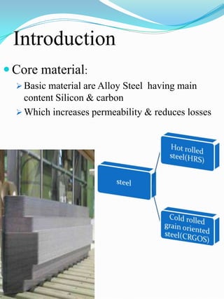
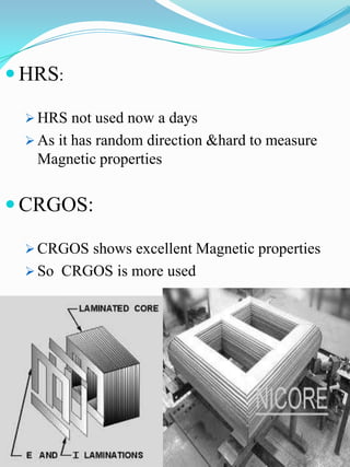
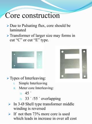
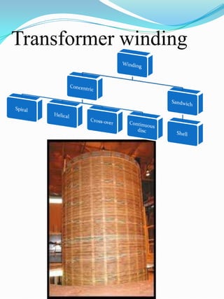
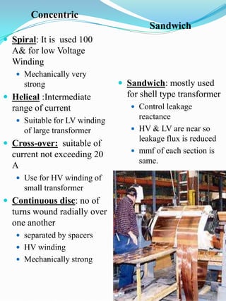
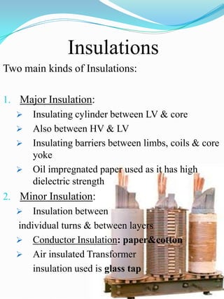
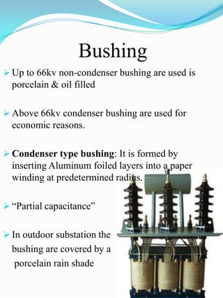
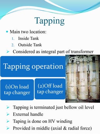
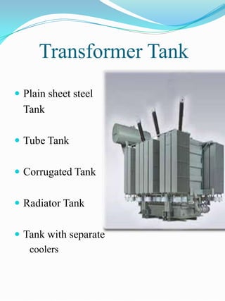
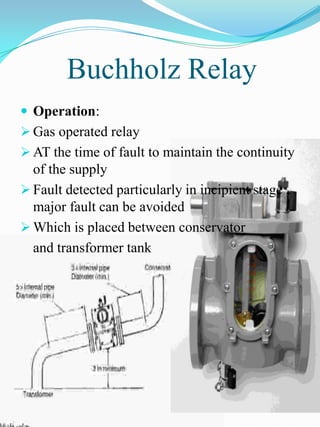
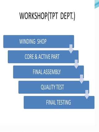
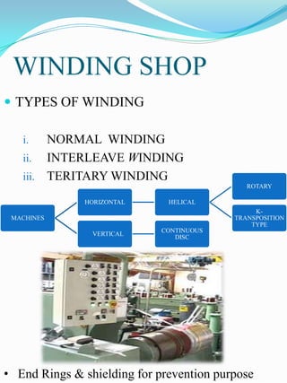
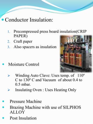
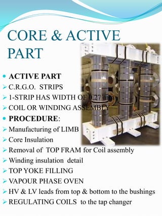
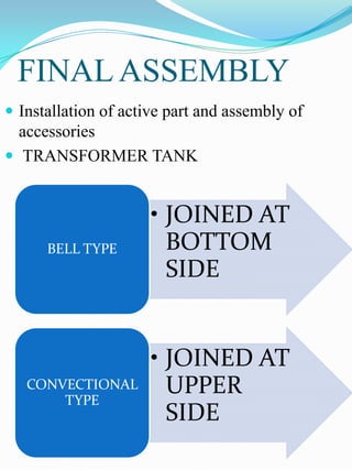

The document outlines the construction and design considerations for transformers, focusing on core materials like crgo, winding types, insulation methods, and cooling systems. It details components such as bushings, conservators, and relays that ensure operational efficiency and safety of transformers. Additionally, it discusses the manufacturing processes and testing protocols essential for transformer quality assurance.

![Transformer Repair Workshop Report [EEE]](https://cdn.slidesharecdn.com/ss_thumbnails/transformerrepairworkshopeee-140621072318-phpapp01-thumbnail.jpg?width=640&height=640&fit=bounds)


