Download to read offline


![proper anchorage for all bars. The main tensile bars of area 𝐴 𝑠 must develop their full yield
strength directly under the load 𝑉𝑢, and for this reason are usually anchored by welding to the
bearing plate or angle. Present ACI Code provisions for the design of brackets and corbels have
been developed, mainly based on tests. They apply to brackets and corbels with a shear span
ratio a/d of 1.0 or less. The distance d is measured at the column face, and the depth at the
outside edge of the bearing area must not be less than 0.5d. The usual design basis is
employed, that is, 𝑀 𝑢 ≤ ∅𝑀 𝑛 and 𝑉𝑢 ≤ ∅𝑉𝑛, and for brackets and corbels (for which shear
dominates the design) ∅ is to be taken equal to 0.85 for all strength calculations.
The section at the face of the support must resist simultaneously the shear 𝑉𝑢, the moment
𝑀 𝑢 = [𝑉𝑢 𝑎 + 𝑁𝑢𝑐(ℎ − 𝑑)], and the horizontal tension𝑁𝑢𝑐. Design for shear is based on the
shear friction method and the total shear reinforcement 𝐴 𝑣𝑓 is found by Eq. (12.4).
𝐴 𝑣𝑓 =
𝑉𝑢
∅𝜇𝑓𝑦
(12.4). The usual limitations that 𝑉𝑛 must not exceed the smaller of 0.2𝑓′ 𝑐 𝐴 𝑐 or
800𝐴 𝑐 apply to the critical section at the support face. (For brackets, 𝐴 𝑐 is to be taken equal to
the area bd according to the ACI Code). Special ACI Code provisions introduce modifications for
lightweight concrete. An amount of steel 𝐴𝑓 to resist the moment 𝑀 𝑢 can be found by the usual
methods for flexural design. Thus: 𝐴 𝑓 =
𝑀 𝑢
𝜑𝑓 𝑦(𝑑−
𝑎
2
)
(12.6)
Where a = 𝐴𝑓 𝑓𝑦/0.85𝑓′ 𝑐 𝑏. An additional area of steel 𝐴 𝑛 must be provided to resist the tensile
component of force. 𝐴 𝑛 =
𝑁 𝑢𝑐
∅𝑓𝑦
(12.7)
Thus, the total area required at the top of the bracket is: 𝐴 𝑠 = 𝐴𝑓 + 𝐴 𝑛 (12.8)
In addition, according to the ACI Code, the area 𝐴 𝑠 must not be less than:
𝐴3 =
2
3
𝐴 𝑣𝑓 + 𝐴 𝑛 (12.9)
An additional restriction, that 𝐴 𝑠 must not be less than 0.04(𝑓′ 𝑐/𝑓𝑦)𝑏𝑑, is intended to avoid the
possibility of sudden failure upon formation of a flexural tensile crack at the top of the bracket.
Closed-hoop stirrups having area 𝐴ℎ not less than 0.5(𝐴 𝑠 − 𝐴 𝑛) n=must be provided, uniformly
distributed within two-thirds of the effective depth adjacent to and parallel to 𝐴 𝑠.
LIFT SLAB CONSTRUCTION
A form of on-site precast construction that has been widely exploited employs what is known as
the lift-slab technique. A casting bed, often doubling as the ground floor slab, is poured,
columns are erected and braced, and at ground level successive slabs, which will later become
upper floors, are cast. A membrane or sprayed parting agent is laid down between successive
pours so that each slab can be lifted in its turn. Jacks placed atop the columns are connecting,
in turn, to lifting collars embedded in the slabs.
Columns may be steel or concrete. Often tubular steel sections are used. When a slab is in its
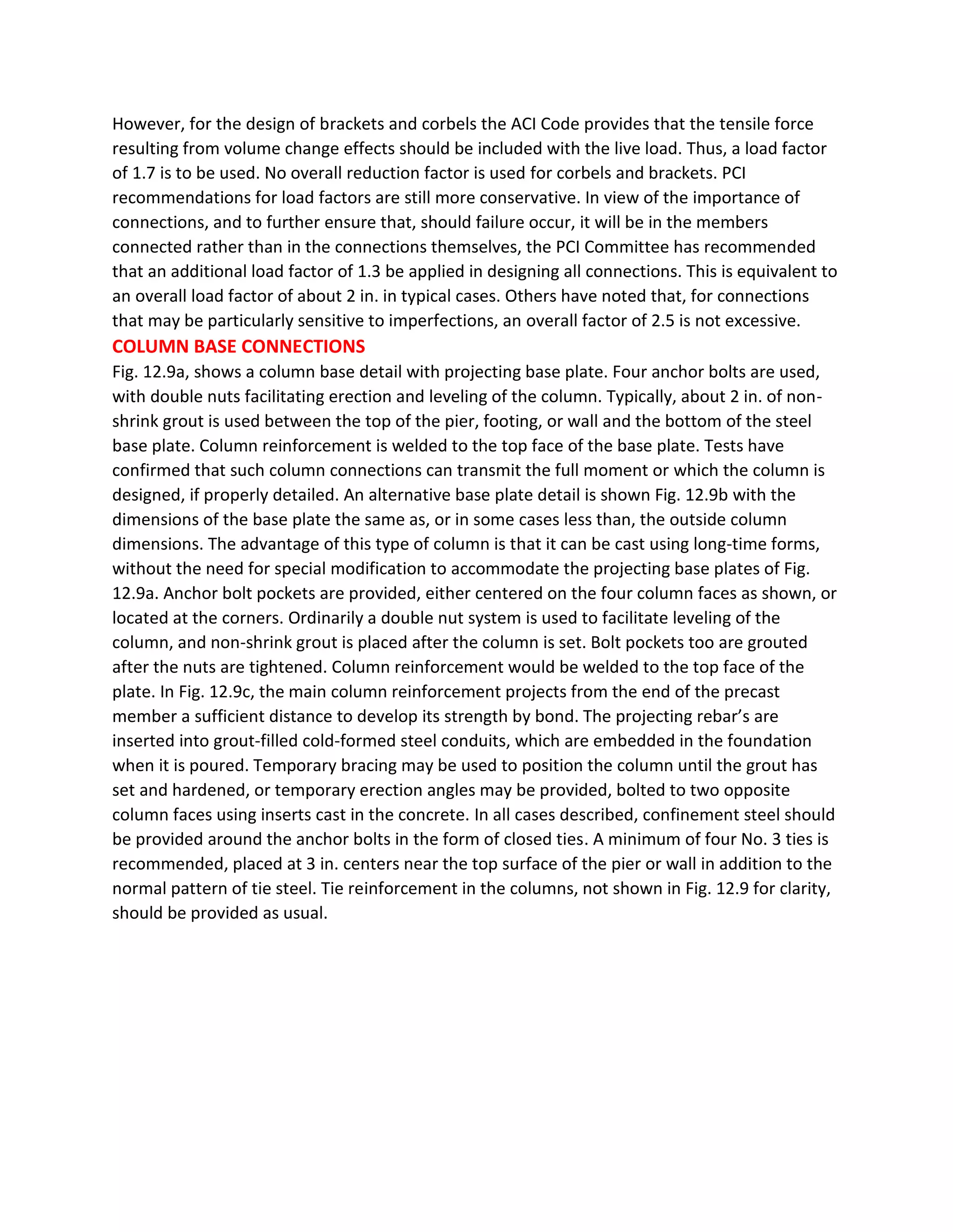
final position, shear keys are welded to the column to transfer vertical reactions from the slab.
Lift-slab construction almost invariably implies flat plate construction with no beams, dropped
panels, or column capitals, for obvious reasons. The slabs are normally post-tensioned using
unbonded strand encased in plastic tubing.](https://image.slidesharecdn.com/pre-stressedpre-castconcretetechnology-ce462-201009030011/75/Pre-stressed-amp-pre-cast-concrete-technology-ce462-80-2048.jpg)


1) Precast concrete consists of concrete elements that are cast and cured off-site and then transported for assembly. Prestressed concrete uses high-strength steel strands or bars that are tensioned to put the concrete in compression and improve its strength. 2) Common precasting techniques include pre-tensioning, where steel is tensioned before the concrete is poured, and post-tensioning, where steel is tensioned after the concrete cures. 3) Advantages of prestressed concrete include reduced cracking, lighter weight, and improved durability; disadvantages include higher material costs and need for specialized equipment.


![Vibe Coding vs. Spec-Driven Development [Free Meetup]](https://cdn.slidesharecdn.com/ss_thumbnails/vibecodingvsspecdrivendevelopment-251209105622-43f455e7-thumbnail.jpg?width=640&height=640&fit=bounds)


