Downloaded 29 times

![Power Converters
Note:
All simulation results are taken by using mosfet at frequency of
Buck BOOST CONVERTER
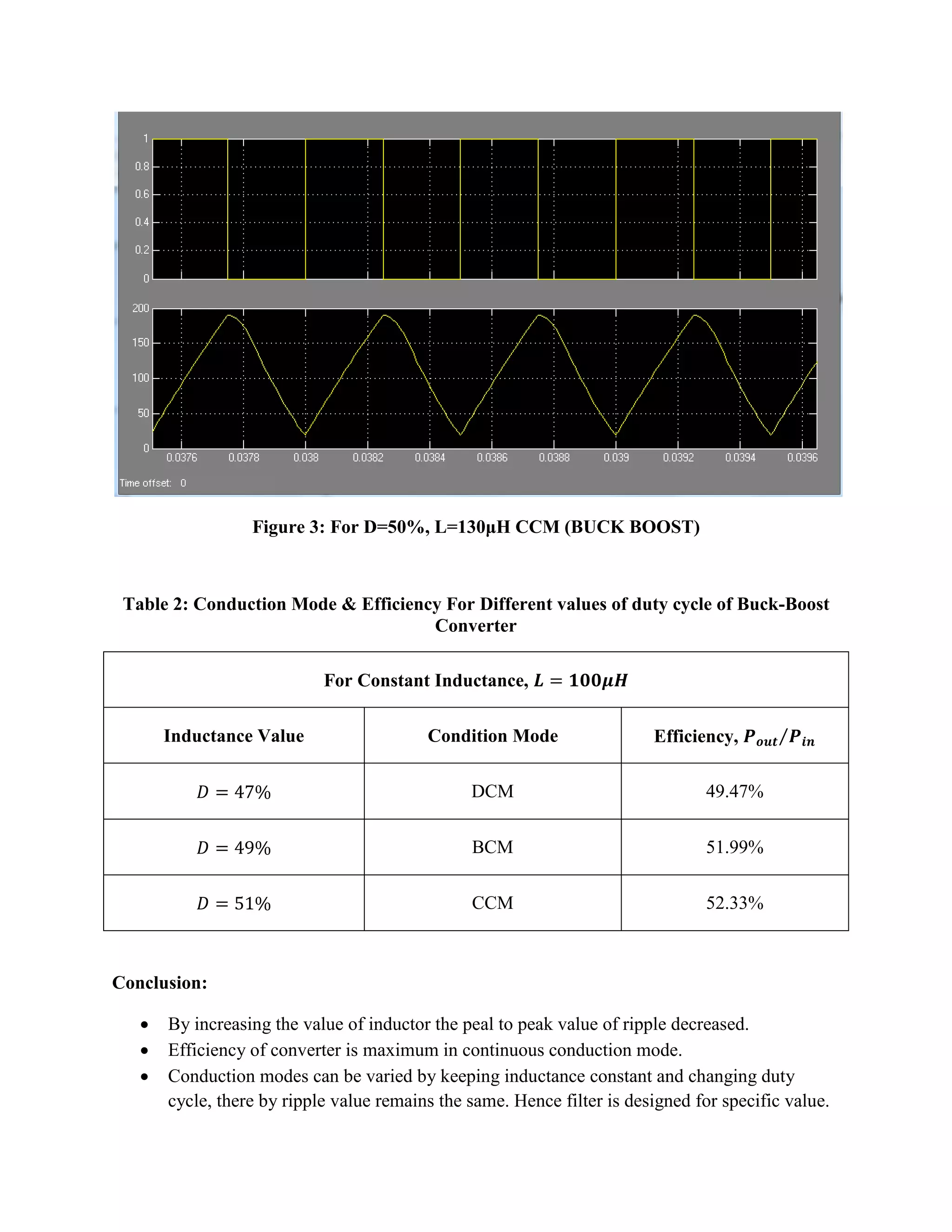
Table 1: Conduction Mode & Efficiency For Different values of duty cycle of Buck-Boost Converter
For Constant Duty Cycle,
Inductance Value
Condition Mode
Efficiency,
DCM
50.71%
BCM
57.02%
CCM
57.53%
Continuouspowergui v+ - V2v+ - V1Scope2Scope1R1PulseGenerator1gmDSMosfetInMeanMean Value3L1i+ - IL2i+ - IL1i+ - IL[H] Goto[H] FromDisplay1Diode1DC Voltage Source1C1](https://image.slidesharecdn.com/powerconverterreporttt-141103072535-conversion-gate02/75/Power-converter-report-2-2048.jpg)

![Buck CONVERTER
Table 3: Conduction Mode & Efficiency For Different values of Inductance of Buck Converter
For Constant Duty Cycle,
Inductance Value
Condition Mode
Efficiency,
DCM
62.27%
BCM
64.78%
CCM
66.56%
Continuouspowerguiv+ - VScope3RPulseGeneratorgmDSMosfet1InMeanMean Value3InMeanMean Value2InMeanMean Value1Li+ - I_L2i+ - I_L1i+ - I_L[E] Goto1Divide2Divide1Divide0.6656DisplayDiodeDC Voltage Source10ConstantC](https://image.slidesharecdn.com/powerconverterreporttt-141103072535-conversion-gate02/75/Power-converter-report-5-2048.jpg)


![Boost CONVERTER
Table 5: Conduction Mode & Efficiency For Different values of Inductance of Boost Converter
For Constant Duty Cycle,
Inductance Value
Condition Mode
Efficiency,
DCM
74.91%
BCM
76.47%
CCM
79.28%
Continuouspowerguiv+ - V2Scope1R2PulseGenerator2InMeanMean Value3InMeanMean Value2InMeanMean Value1L2 gm12 Ideal Switch2i+ - I_L1[A] Goto2Divide2Divide1Divide0.5182DisplayDiode2DC Voltage Source2i+ - Current Measurement10ConstantC2](https://image.slidesharecdn.com/powerconverterreporttt-141103072535-conversion-gate02/75/Power-converter-report-8-2048.jpg)
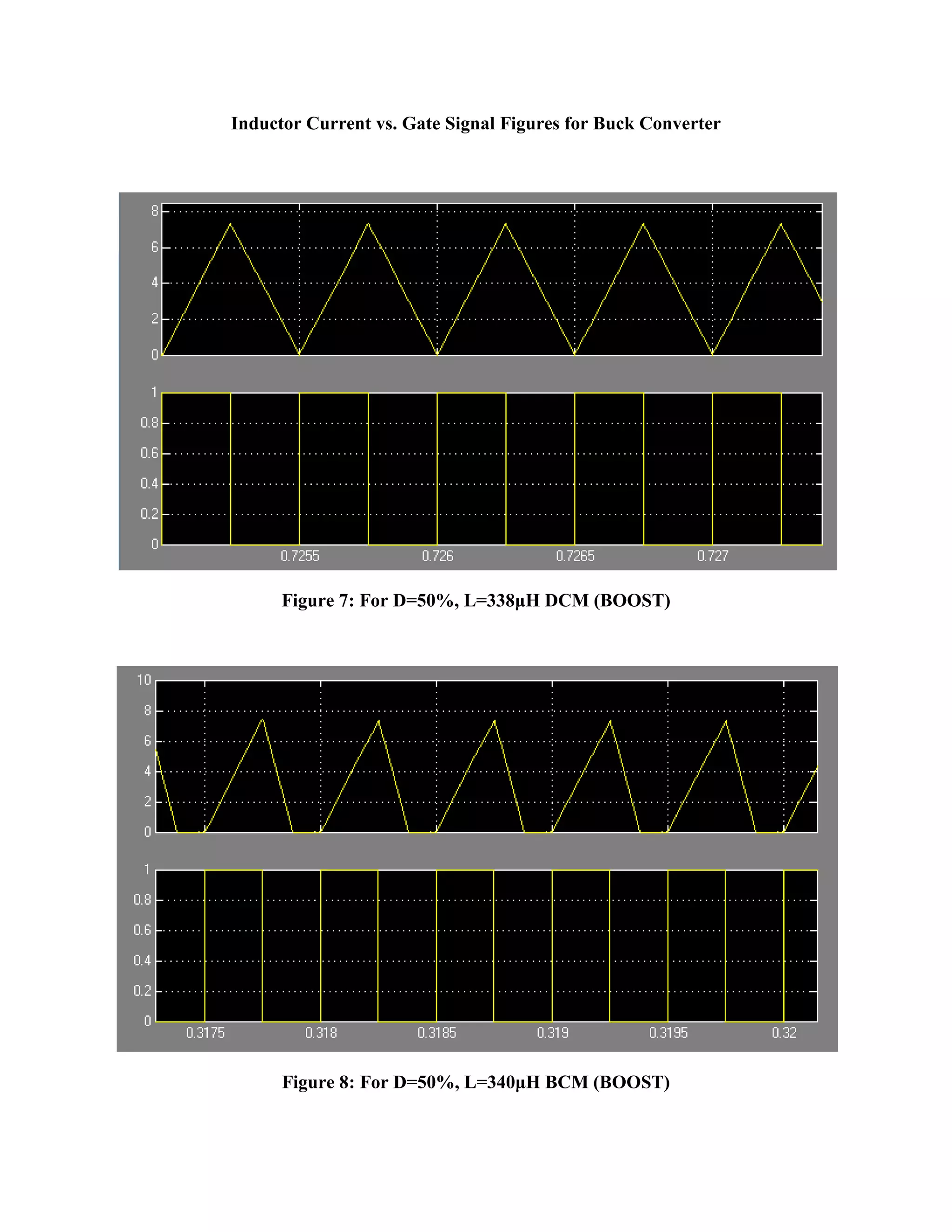


The document analyzes the conduction modes and efficiency of buck-boost, buck, and boost power converters. Simulation results show that continuous conduction mode (CCM) has the highest efficiency for all three converters. For a given duty cycle, increasing the inductor value decreases the peak-to-peak ripple. The conduction mode can also be varied by keeping the inductance constant and changing the duty cycle, which keeps the ripple value the same. Therefore, the filter is designed for a specific inductance value. Tables of results are presented comparing efficiency for different conduction modes under varying duty cycles and inductance values.


