This paper investigates the nonlinear behavior of a current mode controlled buck-boost converter and explores methods to control chaos through the weak periodic perturbation (WPP) technique. The study shows how variations in inductor current can lead to chaotic behavior, and how WPP can stabilize the system to achieve periodic operation. Simulations using MATLAB/Simulink validate that WPP effectively transforms chaotic behavior into stable periodic states.
![International Journal of Power Electronics and Drive System (IJPEDS)
Vol. 8, No. 4, December 2017, pp. 1467~1480
ISSN: 2088-8694, DOI: 10.11591/ijpeds.v8i4.pp1467-1480 1467
Journal homepage: http://iaesjournal.com/online/index.php/IJPEDS
Control of Chaos in a Current Mode Controlled Buck Boost
Converter Using Weak Periodic Perturbation Method
P. Sriramalakshmi1
, A. Kavitha2
, P. Sanjeevikumar3
, Tole Sutikno4
, Pandav Kiran Maroti5
,
Vigna K. Ramachandaramurthy6
1
School of Electrical Engineering, VIT University, Chennai, India
2
Department of Electrical and Electronics Engineering, Anna University, Chennai, India
3,5
Department of Electrical and Electronics Engineering, University of Johannesburg, Auckland Park, South Africa
4
Department of Electrical Engineering, Universitas Ahmad Dahlan (UAD), Yogyakarta, Indonesia
6
Department of Electrical Power Engineering, Universiti Tenaga Nasional, 43000, Kajang, Selangor, Malaysia
Article Info ABSTRACT
Article history:
Received Aug 20, 2017
Revised Sep 3, 2017
Accepted Sep 29, 2017
This paper analyses the nonlinear phenomena in current mode controlled
buck-boost converter. The system undergoes various operating regions
whenever there is a change in non linear elements presented in the system as
well as in the loads. In this work, inductor current is considered as the
reference for analysis.The results show that the converter enters into
period-1, periodic doubling and chaotic regions as per the parameter (IL)
variations. The proposed control strategy, weak periodic perturbation (WPP)
method tries to stabilize the system from the chaotic behavior.The buck boost
converter along with the control system is simulated using
MATLAB/SIMULINK software tool and the results are presented.The
hardware implementation of the system is done and the results are verified
with the simulation results. It shows that the WPP can transform the system
behaviour from the chaotic region to the periodic one.
Keyword:
Bifurcation
Buck-Boost-converter
chaos
Current mode control
Weak Periodic Perturbation
Copyright © 2017 Institute of Advanced Engineering and Science.
All rights reserved.
Corresponding Author:
P. Sanjeevikumar,
Department of Electrical Engineering Science,
University of Johannesburg,
B2 Lab 111, Kingway Campus, PO Box 524 Auckland Park, Johanneburg 2006, South Africa.
Email: sanjeevi_12@yahoo.co.in
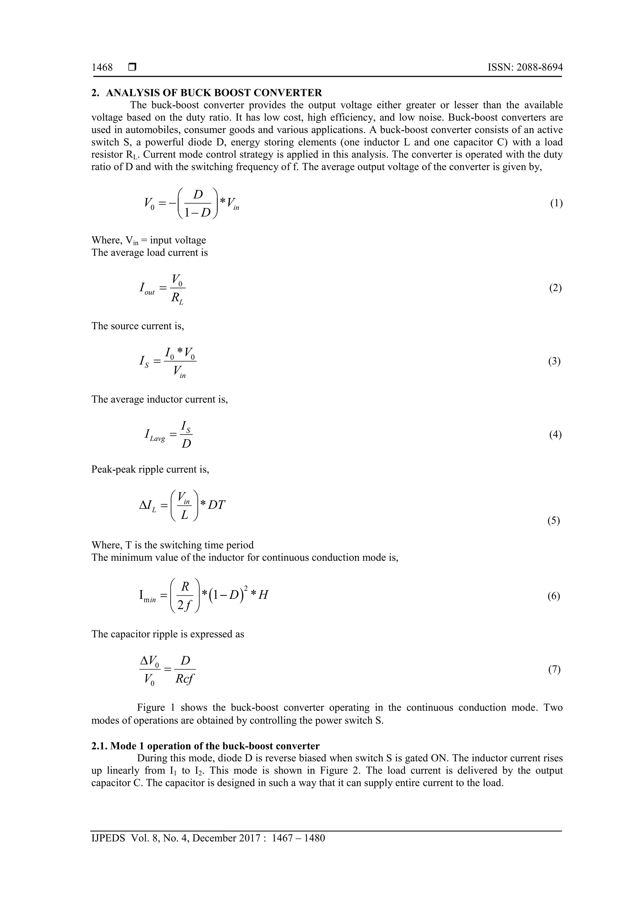
1. INTRODUCTION
The power electronic dc-dc converters are the most non-linear and time varying systems. Since
these topologies have active switches, passive elements and power diodes with nonlinear voltage, current
characteristics, they are dynamic in nature [1]. The operating modes of switching converters are turning into
chaotic very easily [2-4]. A dc-dc buck-boost converter with current mode controlled in continuous
conduction mode gives rise to a great variety of behaviour depending on the parameters of the circuits. The
behaviour of the buck boost converter is analysed with inductor current as the bifurcation parameter [5].
The converter enters into period-1 to the chaotic regime as the inductor current varies. So it is very essential
to implement a control strategy to avoid chaos. There are many control strategies are available in the
literature. There are two different categories, namely feedback and non feedback control methods. Ott-
Grebogi-Yorke (OGY) and Time-delayed frequency control, etc are few of the control methods falling under
feedback control strategies [6-7]. In feedback methods, anyone of the system variable is taken and the control
law is implemented to attain the objective. In non feedback method, system variables need not to be
measured. Any one of the periodic orbit need to be identified as the control target. This paper investigates
current mode controlled buck boost converter with weak periodic perturbation method [8]. Simply, by adding
a weak sinusoidal external force to the original system, narrow and high sub harmonic steps are stabilized.](https://image.slidesharecdn.com/29227-12769-1-pb-210609014908/75/Control-of-Chaos-in-a-Current-Mode-Controlled-Buck-Boost-Converter-Using-Weak-Periodic-Perturbation-Method-1-2048.jpg)
![IJPEDS ISSN: 2088-8694
Control of Chaos in a Current Mode Controlled Buck Boost Converter .... (P. Sriramalakshmi)
1469
2.2. Mode 2 operation of the buck-boost converter
During this mode the switch is OFF at t=tn.The inductor current decreases linearly from I2 to I1.
Figure 3 shows the mode 2 operation of the converter. It is not possible to have a sudden change in inductor
current.So the voltage polarity in the inductor gets reversed to maintain the current constant.The inductor
current decreases till the switch S is gated again. The energy stored in the inductor is delivered to the output
capacitor C. This stored energy in the capacitor is drained out through the load when the switch is ON.
Figure 1. Circuit diagram of buck-boost converter Figure 2. Equivalent circuit for the buck-boost
converter during turn ON
Figure 3. Equivalent circuit of the buck-boost converter during turn OFF.
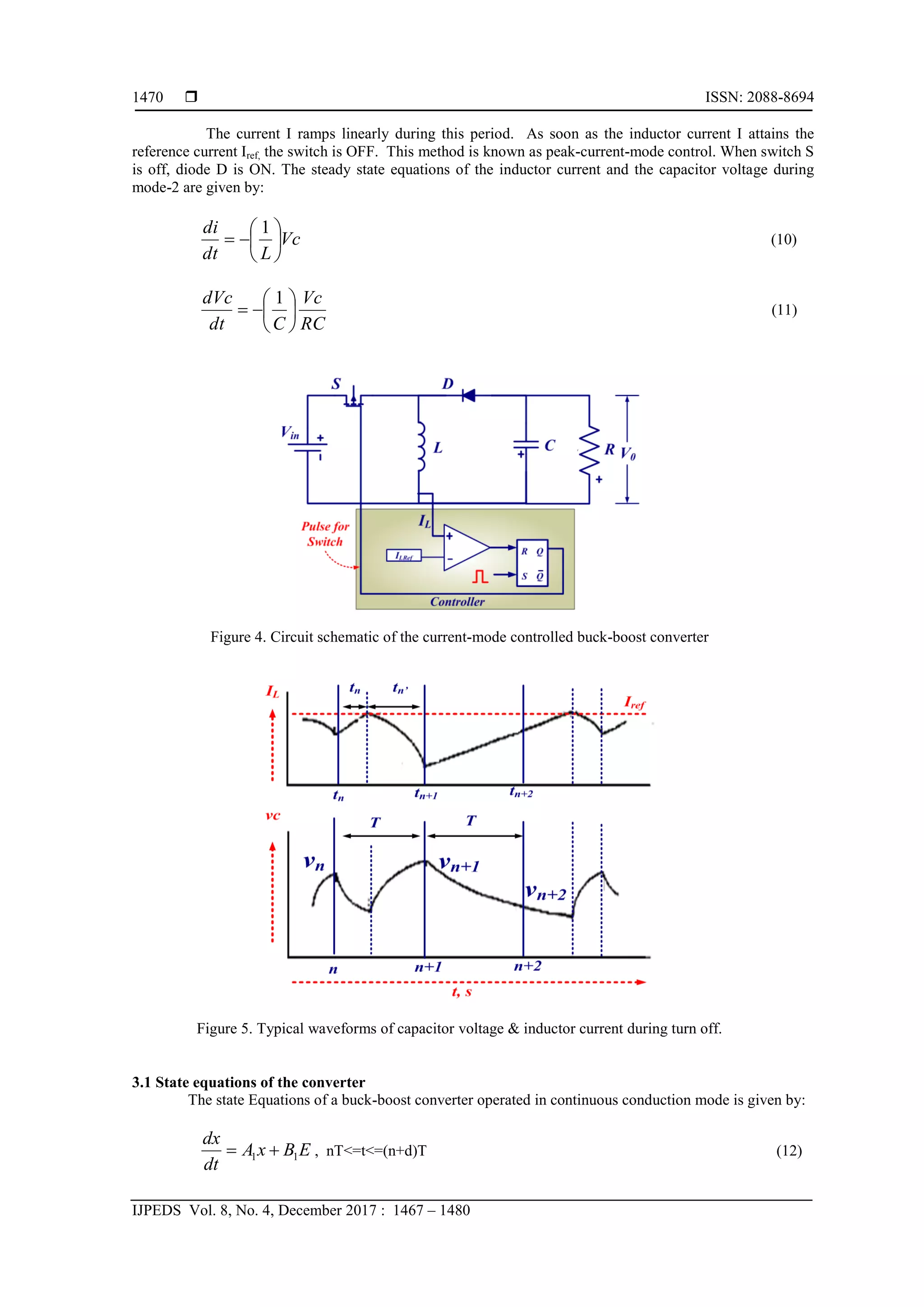
3. OPERATION OF CURRENT PROGRAMMED BUCK-BOOST CONVERTER
The inner loop current controls are usually used for the buck-boost converters since the voltage-
mode control will lead to instability. Also the converter experience right hand side zeroes in voltage mode
control method [5]. The switch S is controlled by a feedback path that consists of a flip-flop and a
comparator. The comparator compares the inductor current IL and a reference current Iref. The power switch
is gated ON when the clock pulse is received and is triggered to OFF when the inductor current reaches Iref.
Figure 4 shows the current-mode controlled buck-boost converter.The inductance value and switching period
T are chosen to operate the converter in continuous conduction mode.The switch S is closed at t=nt. The
inductor current ramps linearly till I= Iref. When I= Iref, the comparator is triggered (Q=0). Then it resets the
clock pulse and triggers S to close again. The inductor current and capacitor voltage are shown in
Figure 5. When switch S is closed, diode D is reversed biased. The steady state equations of the inductor
current and the capacitor voltage during mode-1 are given by:
L
E
dt
di
(8)
Vc
RC
dt
dVc
1 (9)](https://image.slidesharecdn.com/29227-12769-1-pb-210609014908/75/Control-of-Chaos-in-a-Current-Mode-Controlled-Buck-Boost-Converter-Using-Weak-Periodic-Perturbation-Method-3-2048.jpg)
![IJPEDS ISSN: 2088-8694
Control of Chaos in a Current Mode Controlled Buck Boost Converter .... (P. Sriramalakshmi)
1471
2 2
dx
A x B E
dt
, (n+d)T<=t<=(n+1)T (13)
Where, n=integer, T=Period, D=duty cycle, x= [Vc, i]T , i=inductor current.
When switch S is on, A and B is given by,
1 1
1
2
1
1
0
0
C R
A
R
L
, 1
1
0
1
B
L
When switch S is OFF,
1 1 1
2
2
1 1
1 1
1
C R C
A
R
L L
, 1
0
0
B
4. ROUTE TO CHAOS BY VARINGREF
The current programmed buck-boost converter is analysed under various operating regions.The
reference current of the control method is increased for large values of Iref and the system behaviour is
analysed by simulation. The buck-boost converter model is simulated with the following design
specifications articulated in Table 1. The system behaviour from period-1 to chaotic stage is analysed by
varying the reference current in the range of 2.65A to 3A. The system is periodic in nature till the reference
current reaches 2.65A. When the reference current is greater than 2.65A, the system will become more
chaotic.
Tabel 1. Specification Parameter
Sr. No. Parameter Value
1 Input voltage 12V
2 Output voltage 18V
3 Inductor 1mH
4 Capacitor 4 uF
5 Load resistance 20 Ω
6 Frequency (f) 20 kHz
7 Duty cycle (D) 0.6
4.1. Period 1 Operation
It is desirable to operate the system in a fundamental regime which is the stable region of the
system. By keeping the reference current Iref at 2.65A, the period-1 operation is obtained. Figure 6 Shows
the inductor current and output voltage waveform of the period-1 operation which is free from sub
harmonics . The phase portrait of period-1 regime is shown in Figure 7.
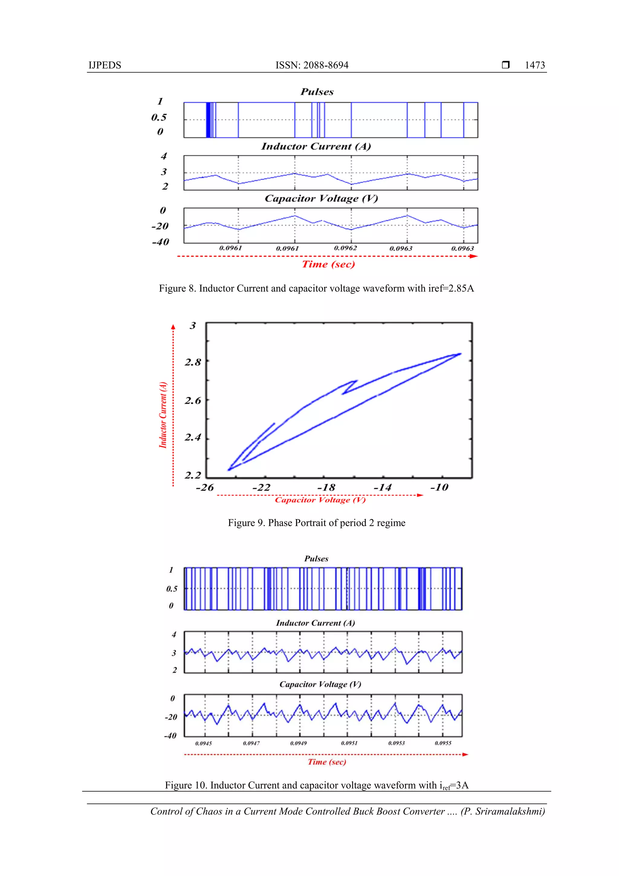
4.2. Period 1 Operation
When the bifurcation parameter Iref is further increased to 2.85A, the period doubling stage is
reached. This stage of operation is mostly avoided by design engineers. The inductor current and load
voltage waveforms for the period-2 regime is shown in the Figure 10 and the corresponding phase portrait is
shown in Figure 9.](https://image.slidesharecdn.com/29227-12769-1-pb-210609014908/75/Control-of-Chaos-in-a-Current-Mode-Controlled-Buck-Boost-Converter-Using-Weak-Periodic-Perturbation-Method-5-2048.jpg)
![ ISSN: 2088-8694
IJPEDS Vol. 8, No. 4, December 2017 : 1467 – 1480
1472
Figure 6. Waveforms of inductor current and capacitor voltage with iref = 2.65A
Figure 7. Phase portrait of period -1 regime
4.3. Chaotic Operation
The chaotic regime is obtained when the value of reference current Iref is increased to 3A. The
simulated waveforms of inductor current and output voltage during chaotic operation are shown in the
Figure 10 and the corresponding phase portrait is shown in Figure 11.
4.4. Bifurcation diagram
Bifurcation diagram can be obtained varying any one of the system parameters, keeping all other
parameters fixed [9]. The bifurcating parameters can be sourced voltage, capacitor voltage, inductor
current, load resistance, inductance, and capacitance or clock frequency. The bifurcating diagram shown in
Figure 12. is obtained by varying the inductor current.If the system is periodic all the points will lie on the
same position.During the chaotic regime, all the points will be scattered and none of the dots will fall on
the same position. Bifurcation diagram is drawn between capacitor voltage and reference current. From the
Figure 9 it is understood that when the reference current is 2.85A, it bifurcates and when the reference
current is 3A it enters into chaotic region.](https://image.slidesharecdn.com/29227-12769-1-pb-210609014908/75/Control-of-Chaos-in-a-Current-Mode-Controlled-Buck-Boost-Converter-Using-Weak-Periodic-Perturbation-Method-6-2048.jpg)
![ ISSN: 2088-8694
IJPEDS Vol. 8, No. 4, December 2017 : 1467 – 1480
1474
5. WEAK PERIODIC PERTURBATION METHOD OF CHAOS CONTROL[10-12]
To operate the system in the desired periodic regime, a small perturbation can be applied. By
applying a small perturbation to a chaotic system, unstable periodic orbits will become stable [13-20]. This
method of control is non-feedback control method. Figure 13. shows the Buck boost converter with weak
periodic perturbation method of control. Any one of system parameter can be considered as control variable
for controlling periodic perturbation, with the following form
x= (1-) x+ (1+sin (2Πft)) (14)
where, x represents the control variable
is the strength of controlling perturbation .
sin (2ft) is the periodic perturbation signal
‗f‘ is the frequency of the perturbation signal.
Without the weak periodic signal the converter experiences the non-periodic oscillations and also it leads to
chaotic operation. When the weak periodic signal acts on the non-periodic signals and chaotic regimes, non
periodic oscillations are broken. The chaotic control of current mode controlled buck boost converter using
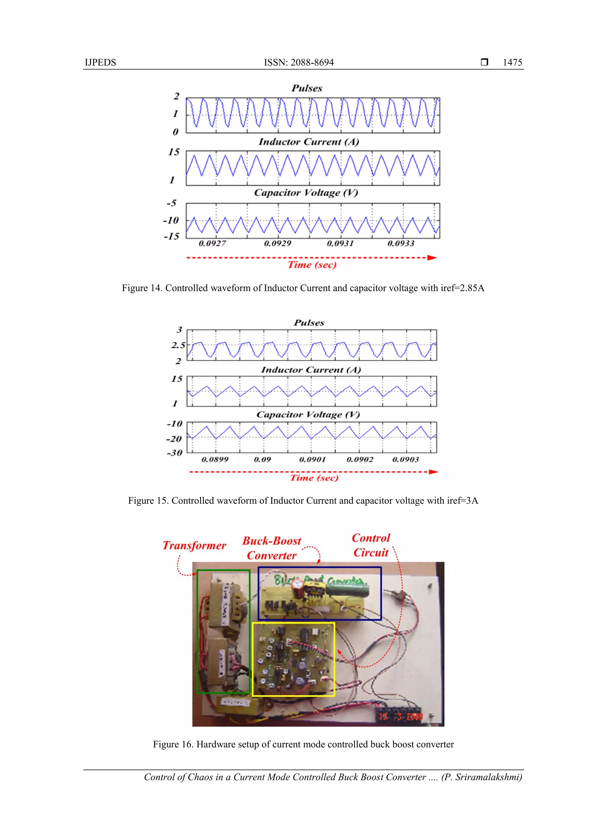
weak periodic perturbation control is simulated using the MATLAB/SIMULINK software [13-31]. The input
voltage is kept fixed at 12V. Without any control, the converter operates in period-2 regime with Iref=2.85A
and in chaotic regime with Iref=3A. With the same Iref, converter operates in period -1 regime when WPP is
applied. It is shown in Figure 14 and Figure 13 [13-20].
Figure 13. Buck-Boost Converter with weak periodic perturbation method of control
Figure 11. Phase Portait of chaotic regime Figure 12. Bifurgation diagram between Iref and Vc](https://image.slidesharecdn.com/29227-12769-1-pb-210609014908/75/Control-of-Chaos-in-a-Current-Mode-Controlled-Buck-Boost-Converter-Using-Weak-Periodic-Perturbation-Method-8-2048.jpg)
![ ISSN: 2088-8694
IJPEDS Vol. 8, No. 4, December 2017 : 1467 – 1480
1476
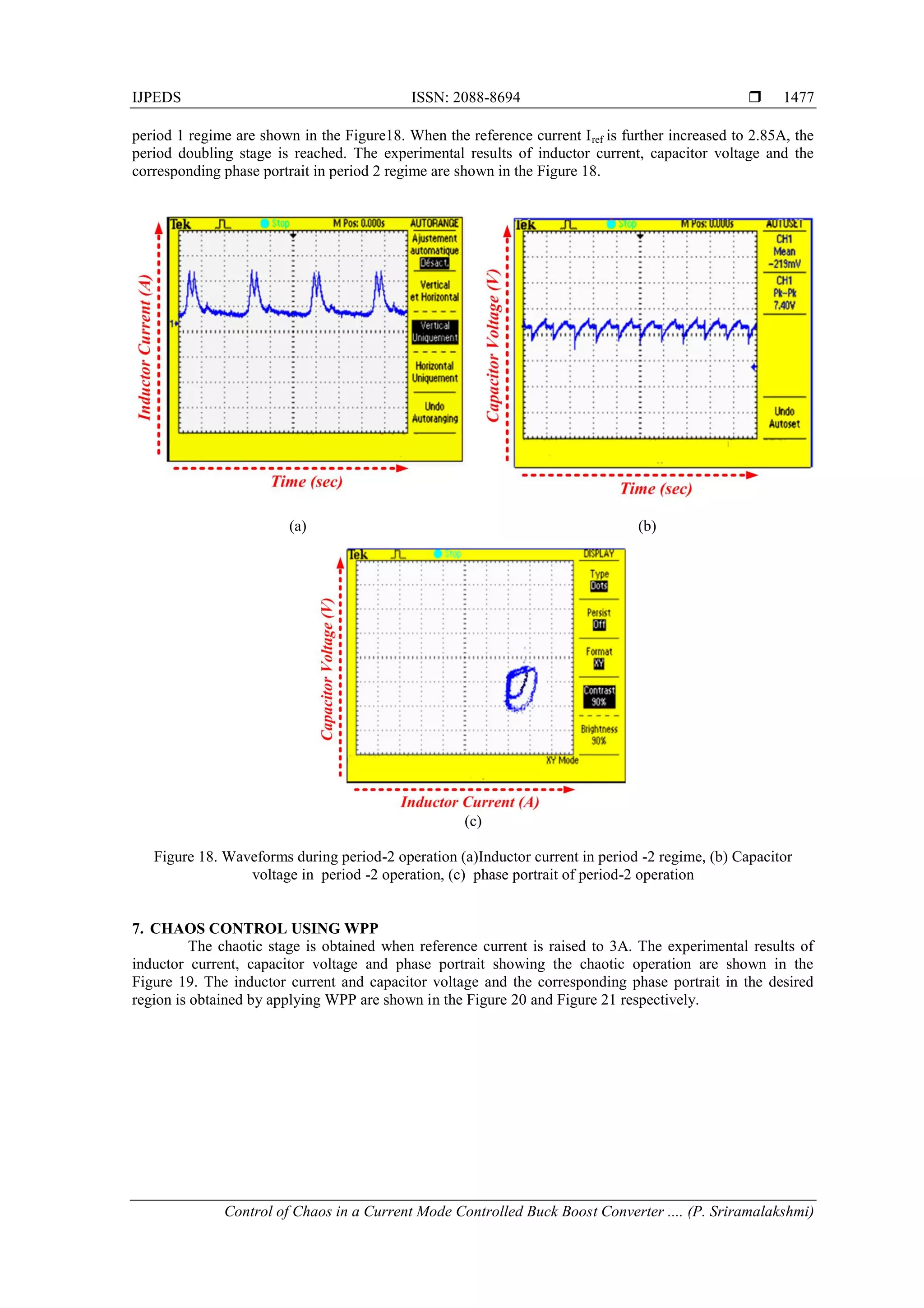
(a) (b)
(c)
Figure 17. Waveforms during period-1 operation (a) Inductor current waveform of period -1 operation, (b)
Capacitor voltage waveform of period -1 operation, (c) phase portrait of period-1 operation
6. HARDWARE IMPLEMENTATION OF CURRENT MODE CONTROLLED BUCK BOOST
CONVERTER
The hardware implementation of buck-boost converter ,including WPP method is shown in
Figure 16. The supply voltage of 230V, 50Hz has been stepped down to 12V with the help of a step down
transformer. A bridge rectifier rectifies ac voltage. After filtering through the capacitors, the required
voltage of +5V for the control circuit was obtained using the regulator chip. The current mode controlled
buck boost converter circuit is shown in the Figure 13.The converter is assumed to be operated in the
continuous conduction mode [21-31].
The control circuit consists of comparator, flip-flop, buffer and a square wave generator, which are
realized by analog and digital devices. The inductor current IL is chosen as the programming variable which
generates the on-off driving signal from the switch S after comparing it with the perturbed reference current
Iref. At the beginning of each cycle, the flip flop is ‗set‘ by the timer, i.e., its output signal is high and the
MOSFET IRF540 is ON. The output signal is low and the MOSFET is OFF when the flip flop is ‗reset‘ by
the output of the comparator. The resistor R is connected in series with the inductor, is used to compare the
inductor current with the reference current Iref.
Therefore the output of the comparator is high when the inductor current reaches the value of Iref,
whereas it is low when the inductor current is less than Iref..The oscillator NE555 has been used for the
generation of clock pulse for the flip flop HCF4013BE. Along with the proper resistor and capacitors, NE555
is used to produce the square wave pulse with the amplitude of 5V, a frequency of 20 KHz and duty cycle of
0.6. The IC LM8038 is used to generate the sine wave signal for the WPP control circuit and MCT2E is the
opto coupler used to couple the control circuit with the driver circuit. The output from the flip flop turns the
the MOSFET through the driver. The buck-boost converter dynamics are studied by varying the reference
current [13-31].
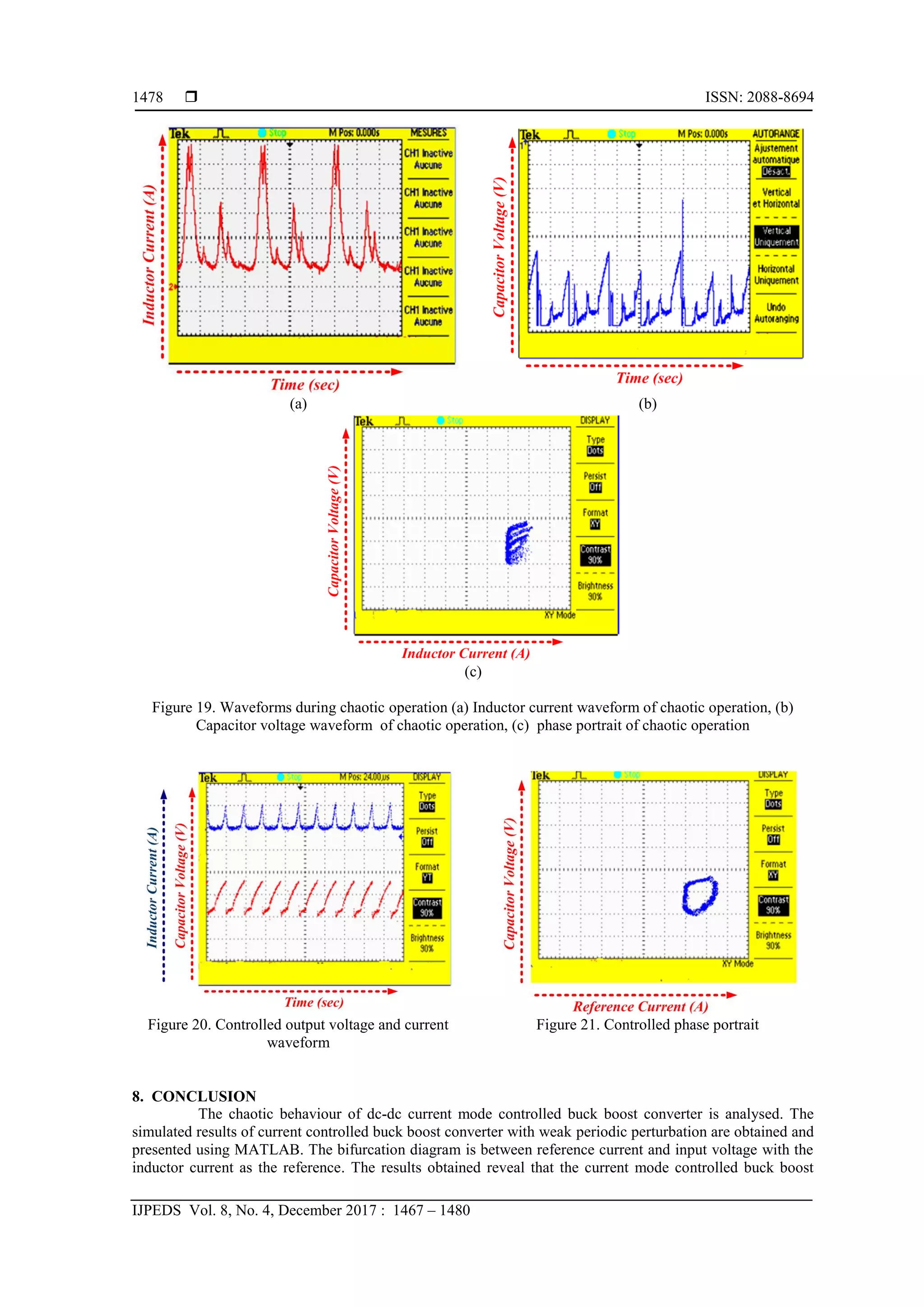
The experimental results of inductor current, capacitor voltage and corresponding phase portrait of](https://image.slidesharecdn.com/29227-12769-1-pb-210609014908/75/Control-of-Chaos-in-a-Current-Mode-Controlled-Buck-Boost-Converter-Using-Weak-Periodic-Perturbation-Method-10-2048.jpg)
![IJPEDS ISSN: 2088-8694
Control of Chaos in a Current Mode Controlled Buck Boost Converter .... (P. Sriramalakshmi)
1479
converter shifts from periodic regime to chaotic regime when the reference current varied from 2.65A to 3A.
The chaotic behaviour is controlled using weak periodic perturbation. It is also realized in hardware and the
results are verified with the simulation results.
REFERENCES
[1] P.Balamurugan, A. Kavitha, P. Sanjeevikumar, J.L. Febin Daya, Tole Sutikno, ―Periodic Perturbation Method for
Controlling Chaos for a Positive Output DC-DC Luo Converter‖, Intl. Journal of Power Electronics and Drive
Systems (IJPEDS), Institute of Advanced Engineering and Science (IAES) Publication, Indonesia, vol. 8, no. 2, pp.
775-784, Jun. 2017.
[2] C.K.Tse and Mario di Bernardo, ―Complex behavior in switching power converters‖, IEEE proceedings, Vol.90,
No.5 May 2002, 768-771.
[3] Ned Mohan and M.Undeland, ―Power Electronics Converters, Application and Design‖, John Wiley and Sons, 1995.
[4] Ilse Cevantes, IEEE member and Jose Alvarez-Ramirez ―A Simple Chaos Control Strategy for DC-DC Power
Converters‖ The 30th Annual Conference of the IEEE Industrial Electronics Society, November 2 - 6,2004, Busan,
Korea
[5] G. Poddar, K. Chakrabarty, and S. Banerjee ―Control of Chaos in DC–DC Converters‖ ‖ IEEE transactions on
circuits and systems-I: Fundamental theory and applications, Vol.45, NO 6, and June 1998.
[6] Ka Wai Eric Cheng, Mingjian Liu, and Yiu Lun Ho ―Experimental Confirmation of Frequency Correlation for
Bifurcation in Current-Mode Controlled Buck-Boost Converters‖ IEEE power electronics letters, Vol 1, NO. 4,
December 2003
[7] Experimental study bifurcation and chaos in Buck-Boost converter, K.W.E. Cheng, M. Liu and J. Wu .* /E€ Pro.-
EIeirce: Powr Appt.. Vol 10, IW,. 1. Jmun. XU3
[8] A.Gupta, S.Banerjee and D.Kastha ―Experimental Study of Bifurcations in the Current Controlled dc-dc Buck-Boost
Converter‖ National Conference on Nonlinear Systems & Dynamics, NCNSD-2003.
[9] Rue-Ron Hsu, Han-Tzong Su, Jyh-Long Chern, and Chia-Chu Chen ―Conditions to Control Chaotic Dynamics by
Weak Periodic Perturbation‖, Vol 78, Number 15,Physical Review Letters.
[10] M.di.Bernardo, L.Glielko, F.Vasca, Feb.1998, ―Switching, bifurcations and chaos in dc-dc converter,‖ IEEE Trans.
Circuits Syst.-Part I, Vol.45, pp.133-141.
[11] Z. Abbadi "Taming chaotic dynamics with weak periodic perturbations: an elucidation and critique". National
Institute of Standards and Technology. Vol. 13, No. 2, 153-156, April 2002.
[12] Wuyin Jin, Jianxue Xu, Ying Wu, Zhiyuan Rui. "Controlling neuronal spike by ion channels with weak periodic
perturbation", Fifth World Congress on Intelligent Control and Automation (IEEE Cat.No.04EX788), 2004
[13] M.S.Bhaskar, P.Sanjeevikumar, Frede Blaabjerg, ―Multistage DC-DC Step-Up Self Balanced and Magnetic
Component Free Converter for Photovoltaic Applications – Hardware Implementation‖, Energies Journal, MDPI
AG Publications, Switzerland, vol. 10, no. 5, Issue 719, pp. 1–28, 18 May 2017.
[14] C.Bharatiraja, S.Raghu, J.L Munda, P.Sanjeevikumar, ―Analysis, Design and Investigation on a New Single-Phase
Switched Quasi Z-Source Inverter for Photovoltaic Application‖, Intl. Journal of Power Electronics and Drive
Systems (IJPEDS), Institute of Advanced Engineering and Science (IAES) Publication, Indonesia, vol. 8, no. 2, pp.
853-860, Jun. 2017.
[15] P.Sanjeevikumar, G.Grandi, Frede Blaabjerg, Patrick Wheeler, Pierluigi Siano, Manel Hammami, ―A
Comprehensive Analysis and Hardware Implementation of Control Strategies for High Output Voltage DC-DC
Boost Power Converter‖, International Journal of Computational Intelligence System (IJCIS), Atlantis Press and
Taylor and Francis publications, vol. 10, no. 1, pp. 140–152, 2017.
[16] P.Sanjeevikumar, Frede Blaabjerg, Patrick Wheeler, Joseph Olorunfemi Ojo, Ahmet H.Ertas, ―High-Voltage DC-
DC Converter Topology for PV Energy Utilization —Investigation and Implementation‖, Journal of Electric Power
Components and Systems, Taylor and Francis publications, pp. 1–12, Dec. 2016.
[17] P.Sanjeevikumar, Ersan Kabalci, Atif Iqbal, Haitham Abu-Rub, Olorunfemi Ojo, ―Control Strategy and Hardware
Implementation for DC-DC Boost Power Conversion Based on Proportional-Integral Compensator for High Voltage
Application‖, Engineering Science and Technology: An International Journal (JESTECH). Elsevier Journal
Publications, vol. 18, no. 2, pp.163–170, Jun. 2015.
[18] P.Sanjeevikumar, K.Rajambal, G.Balaji, ―Investigation of DC-DC converter topologies for future microprocessor‖,
Asian Power Electronics Journal (APEJ) of Research, Power Electronic Research Centre,The Hong kong
Polytechnic University, Hung Hom, Hong Kong, vol. 2, no. 2, pp. 89–95, Oct. 2008. Digital ref: AI70301193.
ISSN: 1995-1051.
[19] P.Sanjeevikumar, K.Rajambal, ―Extra high voltage DC-DC boost converters with simplified control strategy‖,
International Journal of Modeling and Simulation, Hindawi Publishing Corporation, US, vol. 2008, Article ID
593042, 8 pages, Jan. 2008. ISSN: 1697-5591, EISSN: 1687-5605.
[20] M.S.Bhaskar, P.Sanjeevikumar, Viliam Fedák, Frede Blaabjerg, Patrick Wheeler, ―L-L Multilevel Boost Converter
Topology For Renewable Energy Applications: A New Series Voltage Multiplier L-L Converter of XY Family‖,
The 19th IEEE Intl. Conf. on Electrical Drives and Power Electronics, IEEE-EDPE‘17, 4-6 Oct. 2017, Dubrovnik,
Croatia (Europe). (Accepted for Publication).
[21] M.S.Bhaskar, P.Sanjeevikumar, Pandav Kiran Maroti, Viliam Fedák, Frede Blaabjerg, Aishwarya Taur, ―New 2LC-
Y DC-DC Converter Topologies for High-Voltage/Low- Current Renewable Applications: New Members of X-Y](https://image.slidesharecdn.com/29227-12769-1-pb-210609014908/75/Control-of-Chaos-in-a-Current-Mode-Controlled-Buck-Boost-Converter-Using-Weak-Periodic-Perturbation-Method-13-2048.jpg)
![ ISSN: 2088-8694
IJPEDS Vol. 8, No. 4, December 2017 : 1467 – 1480
1480
Converter Family‖, The 19th IEEE Intl. Conf. on Electrical Drives and Power Electronics, IEEE-EDPE‘17, 4-6 Oct.
2017, Dubrovnik, Croatia (Europe). (Accepted for Publication).
[22] T.Anuradha, P.Deiva Sundari, P.Sanjeevikumar, Pierluigi Siano, Zbigniew Leonowicz, ―Comparative Analysis of
Common MPPT Techniques for Solar PV System with Soft Switched, Interleaved Isolated Converter‖, IEEE 1st
Industrial and Commercial Power System Europe, 17th International Conf. on Environment and Electrical Engg.,
IEEE-I&CPS/IEEE-EEEIC'17, Jun. 6-9, 2017, Milan (Italy).
[23] M.S.Bhaskar, P.Sanjeevikumar, Frede Blaabjerg, Lars E.Norum, Ahmet H.Ertas, ―4Nx Non-Isolated and Non-
Inverting Hybrid Interleaved Boost Converter Based On VLSI Cell and Cockroft Walton Voltage Multiplier for
Renewable Energy Applications‖, Proc. of Intl. Conf. on Power Electron., Drives and Energy Systems, IEEE-
PEDES‘16, Kerala (India), 14-17 Dec. 2016.
[24] M.S.Bhaskar, P.Sanjeevikumar, Frede Blaabjerg, Rishi Kulkarni, Sridhar Seshagiri, Amin Hajizadeh, ―Novel LY
DC-DC Converter of XY Family with Minimal Internal Resistance Effect on Output Gain Ratio‖, 4th IET Intl.
Conf. on Clean Energy and Technology, IET-CEAT'16, Kuala Lumpur (Malaysia), 14-15 Nov. 2016.
[25] M.S.Bhaskar, P.Sanjeevikumar, Frede Blaabjerg, Olorunfemi Ojo, Sridhar Seshagiri, Rishi Kulkarni, ―Inverting Nx
and 2Nx Non-Isolated Multilevel Boost Converter For Renewable Energy Application‖, 4th IET Intl. Conf. on
Clean Energy and Technology, IET-CEAT'16, Kuala Lumpur (Malaysia), 14-15 Nov. 2016.
[26] 43. M.S.Bhaskar, P.Sanjeevikumar, Olorunfemi Ojo, Marco Rivera, R.Kulkarani, ―Non-Isolated and Inverting Nx
Multilevel Boost Converter For Photovoltaic DC Link Applications‖, Proc. of IEEE Intl. Conf. on Automatica, XXII
Congress of the Chilean Association of Automatic Control, IEEE-ICA/ACCA‘16, University of Talca, Talca
(Chile), 19-21 Oct. 2016.
[27] M.S. Bhaskar, P. Sanjeevikumar, Pat Wheeler, Frede Blaabjerg, Marco Rivera, Ahmet H.Ertas, R. Kulkarni, ―X-Y
Converter Family: A New Breed of Buck Boost Converter for High Step-up Renewable Energy Applications‖, Proc.
of IEEE Intl. Conf. on Automatica, XXII Congress of the Chilean Association of Automatic Control, IEEE-
ICA/ACCA‘16, University of Talca, Talca (Chile), 19-21 Oct. 2016.
[28] M.S.Bhaskar, P.Sanjeevikumar, Frede Blaaberg, Viliam Fedák, Mihai Cernat, R.Kulkarani, ―Non Isolated and Non-
Inverting Cockcroft Walton Multiplier Based Hybrid 2Nx Interleaved Boost Converter For Renewable Energy
Applications‖, Conf. Prof of The 17th IEEE Power Electronics and Motion Control, IEEE-PEMC‘16, Varna
(Bulgaria), 25-30 Sept. 2016.
[29] P.Sanjeevikumar, Frede Blaabjerg, Pierluigi Siano, Luigi Martirano, Zbigniew Leonowicz, Kiran M. Pandav, ―PI
and Fuzzy Control Strategies for High Voltage Output DC-DC Boost Power Converter – Hardware Implementation
And Analysis‖, Conf. Proc. of 16 IEEE Intl. Conf. on Environment and Electrical Engg., Florence (Italy), 7-10 Jun.
2016.
[30] P. Sanjeevikumar, G.Grandi, Patrick Wheeler, Frede Blaabjerg, J.Loncarski, ―A Simple MPPT Algorithm for Novel
PV Power Generation system by High Output Voltage DC-DC Boost Converter‖, Conf. Proc., 24th IEEE
International Symposium on Industrial Electronics, IEEE-ISIE‘15, Rio de Janeiro (Brazil), pp. 214–220, 3–5 Jun.
2015.
[31] P.Sanjeevikumar, A.Iqbal, Haitham Abu-Rub, ―Implementation and control of extra high voltage dc-dc boost
converter‖, The 7th IET International Conference on Sustainable Energy and Intelligent System, IET-SEISCON‘13,
Chennai (India), pp. 182–188, 12–14 Dec. 2013.](https://image.slidesharecdn.com/29227-12769-1-pb-210609014908/75/Control-of-Chaos-in-a-Current-Mode-Controlled-Buck-Boost-Converter-Using-Weak-Periodic-Perturbation-Method-14-2048.jpg)


![[IJET V2I5P12] Authors: Mr. Harikrishnan U, Dr. Bos Mathew Jos, Mr.Thomas P R...](https://cdn.slidesharecdn.com/ss_thumbnails/ijet-v2i5p12-161107141950-thumbnail.jpg?width=640&height=640&fit=bounds)


