Downloaded 1,213 times


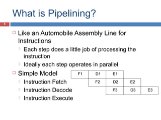
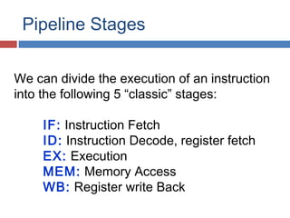
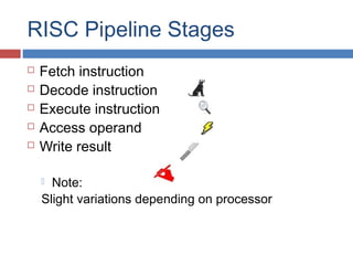
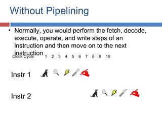
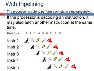
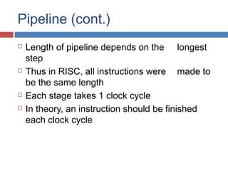
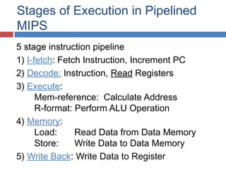
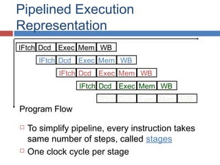
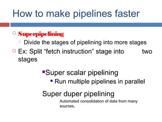
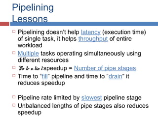
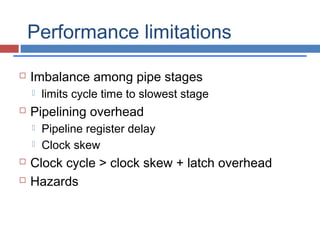

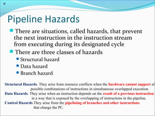
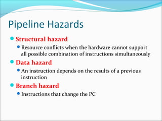
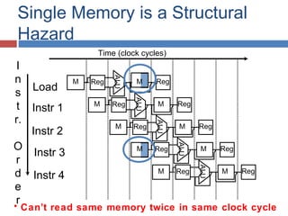
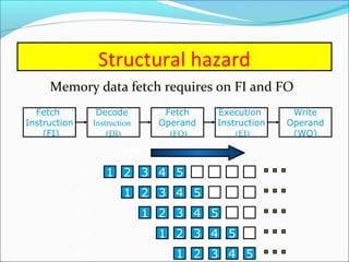
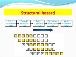
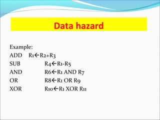
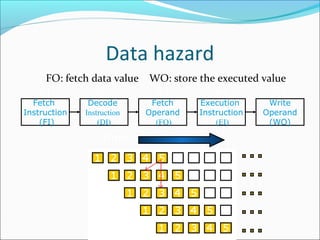
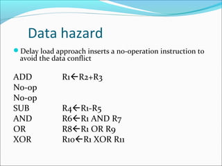
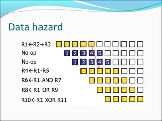
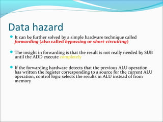
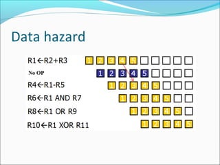
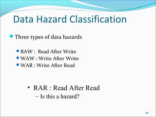
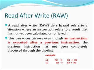
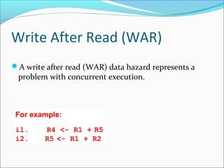
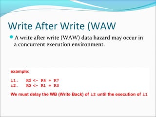
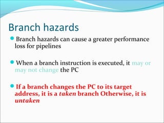
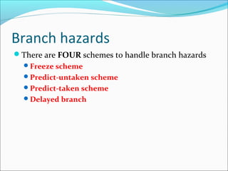
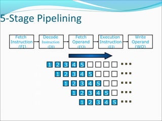
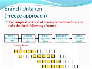
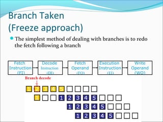
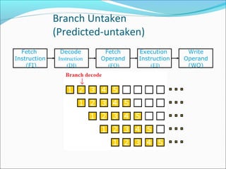
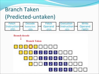
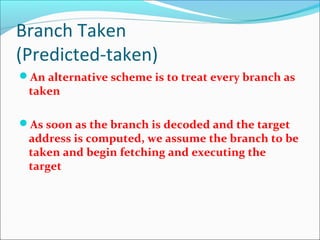
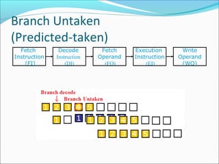
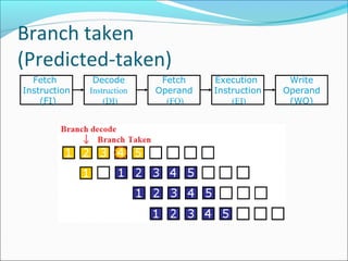
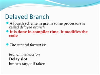
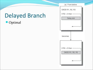
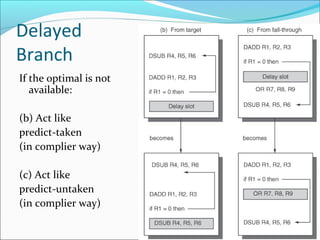
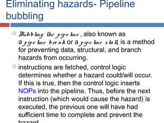

Pipelining is a technique used in processors to divide instruction processing into segments, allowing multiple instructions to be executed concurrently akin to an assembly line. The execution is segmented into stages such as fetch, decode, execute, memory access, and write back, improving overall throughput but introducing potential hazards like structural and data hazards. Solutions to these hazards include reordering instructions, using hardware techniques like forwarding, and implementing branch prediction strategies to maintain efficiency.