Downloaded 626 times
![List of Figures
1.1 Number of survivors and casualties in the Kobe earthquake in 1995. Image
from [267]. . . . . . . . . . . . . . . . . . . . . . . . . . . . . . . . . . . . 3
1.2 Percentage of survival chances in accordance to when victim is located. Based
on [69]. . . . . . . . . . . . . . . . . . . . . . . . . . . . . . . . . . . . . . 3
1.3 70 years for autonomous control levels. Edited from [44]. . . . . . . . . . . . 6
1.4 Mobile robot control scheme. Image from [255]. . . . . . . . . . . . . . . . 9
1.5 Minsky’s interpretation of behaviors. Image from [188]. . . . . . . . . . . . 18
1.6 Classic and new artificial intelligence approaches. Edited from [255]. . . . . 18
1.7 Behavior in robotics control. Image from [138]. . . . . . . . . . . . . . . . . 19
1.8 Coordination methods for behavior-based control. Edited from [11]. . . . . . 19
1.9 Group architecture overview. . . . . . . . . . . . . . . . . . . . . . . . . . . 23
1.10 Service-oriented group architecture. . . . . . . . . . . . . . . . . . . . . . . 25
2.1 Major challenges for networked robots. Image from [150]. . . . . . . . . . . 30
2.2 Typical USAR Scenario. Image from [267]. . . . . . . . . . . . . . . . . . . 30
2.3 Real pictures from the WTC Tower 2. a) shows a rescue robot within the white
box navigating in the rubble; b) robots-eye view with three sets of victim
remains. Image edited from [194] and [193]. . . . . . . . . . . . . . . . . . 31
2.4 Typical problems with rescue robots. Image from [268]. . . . . . . . . . . . . 35
2.5 Template-based information system for disaster response. Image based on [156,
56]. . . . . . . . . . . . . . . . . . . . . . . . . . . . . . . . . . . . . . . . 41
2.6 Examples of templates for disaster response. Image based on [156, 56]. . . . 42
2.7 Task force in rescue infrastructure. Image from [14]. . . . . . . . . . . . . . 43
2.8 Rescue Communicator, R-Comm: a) Long version, b) Short version. Image
from [14]. . . . . . . . . . . . . . . . . . . . . . . . . . . . . . . . . . . . . 43
2.9 Handy terminal and RFID tag. Image from [14]. . . . . . . . . . . . . . . . . 44
2.10 Database for Rescue Management System, DaRuMa. Edited from [210]. . . . 44
2.11 RoboCup Rescue Concept. Image from [270]. . . . . . . . . . . . . . . . . . 46
2.12 USARSim Robot Models. Edited from [284, 67]. . . . . . . . . . . . . . . . 47
2.13 USARSim Disaster Snapshot. Edited from [18, 17]. . . . . . . . . . . . . . . 47
2.14 Sensor Readings Comparison. Top: Simulation, Bottom: Reality. Image
from [67]. . . . . . . . . . . . . . . . . . . . . . . . . . . . . . . . . . . . . 48
2.15 Control Architecture for Rescue Robot Systems. Image from [3]. . . . . . . . 50
2.16 Coordinated exploration using costs and utilities. Frontier assignment consid-
ering a) only costs; b) costs and utilities; c) three robots paths results. Edited
from [58]. . . . . . . . . . . . . . . . . . . . . . . . . . . . . . . . . . . . . 52
vi](https://image.slidesharecdn.com/dtc-phd-thesis-finalversion-121215102213-phpapp01/75/PhD-Thesis-Coordination-of-Multiple-Robotic-Agents-for-Disaster-and-Emergency-Response-8-2048.jpg)
![2.17 Supervisor sketch for MRS patrolling. Image from [168]. . . . . . . . . . . . 53
2.18 Algorithm for determining occupancy grids. Image from [33]. . . . . . . . . 54
2.19 Multi-Robot generated maps in RoboCup Rescue 2007. Image from [225]. . . 55
2.20 Behavioral mapping idea. Image from [164]. . . . . . . . . . . . . . . . . . . 55
2.21 3D mapping using USARSim. Left) Kurt3D and its simulated counterpart.
Right) 3D color-coded map. Edited from [20]. . . . . . . . . . . . . . . . . . 56
2.22 Face recognition in USARSim. Left) Successful recognition. Right) False
positive. Image from [20]. . . . . . . . . . . . . . . . . . . . . . . . . . . . 57
2.23 Human pedestrian vision-based detection procedure. Image from [90]. . . . . 57
2.24 Human pedestrian vision-based detection procedure. Image from hal.inria.fr/inria-
00496980/en/. . . . . . . . . . . . . . . . . . . . . . . . . . . . . . . . . . . 58
2.25 Human behavior vision-based recognition. Edited from [207]. . . . . . . . . 58
2.26 Visual path following procedure. Edited from [103]. . . . . . . . . . . . . . . 59
2.27 Visual path following tests in 3D terrain. Edited from [103]. . . . . . . . . . 59
2.28 START Algorithm. Victims are sorted in: Minor, Delayed, Immediate and
Expectant; based on the assessment of: Mobility, Respiration, Perfusion and
Mental Status. Image from [80]. . . . . . . . . . . . . . . . . . . . . . . . . 61
2.29 Safety, security and rescue robotics teleoperation stages. Image from [36]. . . 61
2.30 Interface for multi-robot rescue systems. Image from [209]. . . . . . . . . . . 62
2.31 Desired information for rescue robot interfaces: a)multiple image displays, b)
multiple map displays. Edited from [292]. . . . . . . . . . . . . . . . . . . . 63
2.32 Touch-screen technologies for rescue robotics. Edited from [185]. . . . . . . 64
2.33 MRS for autonomous exploration, mapping and deployment. a) the complete
heterogeneous team; b) sub-team with mapping capabilities. Image from [130]. 65
2.34 MRS result for autonomous exploration, mapping and deployment. a) origi-
nal floor map; b) robots collected map; c) autonomous planned deployment.
Edited from [130]. . . . . . . . . . . . . . . . . . . . . . . . . . . . . . . . 65
2.35 MRS for search and monitoring: a) Piper J3 UAVs; b) heterogeneous UGVs.
Edited from [131]. . . . . . . . . . . . . . . . . . . . . . . . . . . . . . . . 66
2.36 Demonstration of integrated search operations: a) robots at initial positions, b)
robots searching for human target, c) alert of target found, d) display nearest
UGV view of the target. Edited from [131]. . . . . . . . . . . . . . . . . . . 67
2.37 CRASAR MicroVGTV and Inuktun [91, 194, 158, 201]. . . . . . . . . . . . 70
2.38 TerminatorBot [282, 281, 204]. . . . . . . . . . . . . . . . . . . . . . . . . . 70
2.39 Leg-in-Rotor Jumping Inspector [204, 267]. . . . . . . . . . . . . . . . . . . 71
2.40 Cubic/Planar Transformational Robot [266]. . . . . . . . . . . . . . . . . . . 71
2.41 iRobot ATRV - FONTANA [199, 91, 158]. . . . . . . . . . . . . . . . . . . . 71
2.42 FUMA [181, 245]. . . . . . . . . . . . . . . . . . . . . . . . . . . . . . . . 72
2.43 Darmstadt University - Monstertruck [8]. . . . . . . . . . . . . . . . . . . . 72
2.44 Resko at UniKoblenz - Robbie [151]. . . . . . . . . . . . . . . . . . . . . . 72
2.45 Independent [84]. . . . . . . . . . . . . . . . . . . . . . . . . . . . . . . . . 73
2.46 Uppsala University Sweden - Surt [211]. . . . . . . . . . . . . . . . . . . . . 73
2.47 Taylor [199]. . . . . . . . . . . . . . . . . . . . . . . . . . . . . . . . . . . 73
2.48 iRobot Packbot [91, 158]. . . . . . . . . . . . . . . . . . . . . . . . . . . . . 74
2.49 SPAWAR Urbot [91, 158]. . . . . . . . . . . . . . . . . . . . . . . . . . . . 74
vii](https://image.slidesharecdn.com/dtc-phd-thesis-finalversion-121215102213-phpapp01/75/PhD-Thesis-Coordination-of-Multiple-Robotic-Agents-for-Disaster-and-Emergency-Response-9-2048.jpg)
![2.50 Foster-Miller Solem [91, 194, 158]. . . . . . . . . . . . . . . . . . . . . . . 74
2.51 Shinobi - Kamui [189]. . . . . . . . . . . . . . . . . . . . . . . . . . . . . . 75
2.52 CEO Mission II [277]. . . . . . . . . . . . . . . . . . . . . . . . . . . . . . 75
2.53 Aladdin [215, 61]. . . . . . . . . . . . . . . . . . . . . . . . . . . . . . . . . 75
2.54 Pelican United - Kenaf [204, 216]. . . . . . . . . . . . . . . . . . . . . . . . 76
2.55 Tehzeeb [265]. . . . . . . . . . . . . . . . . . . . . . . . . . . . . . . . . . 76
2.56 ResQuake Silver2009 [190, 187]. . . . . . . . . . . . . . . . . . . . . . . . 76
2.57 Jacobs Rugbot [224, 85, 249]. . . . . . . . . . . . . . . . . . . . . . . . . . 77
2.58 PLASMA-Rx [87]. . . . . . . . . . . . . . . . . . . . . . . . . . . . . . . . 77
2.59 MRL rescue robots NAJI VI and NAJI VII [252]. . . . . . . . . . . . . . . . 77
2.60 Helios IX and Carrier Parent and Child [121, 180, 267]. . . . . . . . . . . . . 78
2.61 KOHGA : Kinesthetic Observation-Help-Guidance Agent [142, 181, 189, 276]. 78
2.62 OmniTread OT-4 [40]. . . . . . . . . . . . . . . . . . . . . . . . . . . . . . 78
2.63 Hyper Souryu IV [204, 276]. . . . . . . . . . . . . . . . . . . . . . . . . . . 79
2.64 Rescue robots: a) Talon, b) Wolverine V-2, c) RHex, d) iSENSYS IP3, e)
Intelligent Aerobot, f) muFly microcopter, g) Chinese firefighting robot, h)
Teleoperated extinguisher, i) Unmanned surface vehicle, j) Predator, k) T-
HAWK, l) Bluefin HAUV. Images from [181, 158, 204, 267, 287]. . . . . . . 80
2.65 Jacobs University rescue arenas. Image from [249]. . . . . . . . . . . . . . . 81
2.66 Arena in which multiple Kenafs were tested. Image from [205]. . . . . . . . 82
2.67 Exploration strategy and centralized, global 3D map: a) frontiers in current
global map, b) allocation and path planning towards the best frontier, c) a
final 3D global map. Image from [205]. . . . . . . . . . . . . . . . . . . . . 82
2.68 Mapping data: a) raw from individual robots, b) fused and corrected in a new
global map. Image from [205]. . . . . . . . . . . . . . . . . . . . . . . . . . 83
2.69 Building exploration and temperature gradient mapping: a) robots as mobile
sensors navigating and deploying static sensors, b) temperature map. Image
from [144]. . . . . . . . . . . . . . . . . . . . . . . . . . . . . . . . . . . . 84
2.70 Building structure exploration and temperature mapping using static sensors,
human mobile sensor, and UAV mobile sensor. Image from [98]. . . . . . . . 84
2.71 Helios IX in a door-opening procedure. Image from [121]. . . . . . . . . . . 85
2.72 Real model and generated maps of the 60 m. hall: a) real 3D model, b)
generated 3D map with snapshots, c) 2D map with CPS, d) 2D map with dead
reckoning. Image from [121]. . . . . . . . . . . . . . . . . . . . . . . . . . . 86
2.73 IRS-U and K-CFD real tests with rescue robots: a) deployment of Kohga
and Souryu robots, b) Kohga finding a victim, c) operator being notified of
victim found, d) Kohga waiting until human rescuer assists the victim, e)
Souryu finding a victim, f) Kohga and Souryu awaiting for assistance, g) hu-
man rescuers aiding the victim, and h) both robots continue exploring. Images
from [276]. . . . . . . . . . . . . . . . . . . . . . . . . . . . . . . . . . . . 87
2.74 Types of entries in mine rescue operations: a) Surface Entry (SE), b) Borehole
Entry (BE), c) Void Entry (VE), d) Inuktun being deployed in a BE [201]. . . 89
2.75 Standardized test arenas for rescue robotics: a) Red Arena, b) Orange Arena,
c) Yellow Arena. Image from [67]. . . . . . . . . . . . . . . . . . . . . . . . 91
viii](https://image.slidesharecdn.com/dtc-phd-thesis-finalversion-121215102213-phpapp01/75/PhD-Thesis-Coordination-of-Multiple-Robotic-Agents-for-Disaster-and-Emergency-Response-10-2048.jpg)
![3.1 MaSE Methodology. Image from [289]. . . . . . . . . . . . . . . . . . . . . 94
3.2 USAR Requirements (most relevant references to build this diagram include:
[261, 19, 80, 87, 254, 269, 204, 267, 268]). . . . . . . . . . . . . . . . . . . 96
3.3 Sequence Diagram I: Exploration and Mapping (most relevant references to
build this diagram include: [173, 174, 175, 176, 21, 221, 86, 232, 10, 58, 271,
101, 33, 240, 92, 126, 194, 204]). . . . . . . . . . . . . . . . . . . . . . . . . 99
3.4 Sequence Diagram IIa: Recognize and Identify - Local (most relevant refer-
ences to build this diagram include: [170, 175, 221, 23, 242, 163, 90, 207, 89,
226]). . . . . . . . . . . . . . . . . . . . . . . . . . . . . . . . . . . . . . . 100
3.5 Sequence Diagram IIb: Recognize and Identify - Remote (most relevant ref-
erences to build this diagram include: [170, 175, 221, 23, 242, 163, 90, 207,
89, 226]). . . . . . . . . . . . . . . . . . . . . . . . . . . . . . . . . . . . . 101
3.6 Sequence Diagram III: Support and Relief (most relevant references to build
this diagram include: [58, 33, 80, 19, 226, 150, 267, 204, 87, 254]). . . . . . . 102
3.7 Robots used in this dissertation: to the left a simulated version of an Adept
Pioneer 3DX, in the middle the real version of an Adept Pioneer 3AT, and to
the right a Dr. Robot Jaguar V2. . . . . . . . . . . . . . . . . . . . . . . . . 103
3.8 Roles, behaviors and actions mappings. . . . . . . . . . . . . . . . . . . . . 106
3.9 Roles, behaviors and actions mappings. . . . . . . . . . . . . . . . . . . . . 107
3.10 Behavior-based control architecture for individual robots. Edited image from [178].108
3.11 The Hybrid Paradigm. Image from [192]. . . . . . . . . . . . . . . . . . . . 109
3.12 Group architecture. . . . . . . . . . . . . . . . . . . . . . . . . . . . . . . . 110
3.13 Architecture topology: at the top the system element communicating wireless
with the subsystems. Subsystems include their nodes, which can be differ-
ent types of computers. Finally, components represent the running software
services depending on the existing hardware and node’s capabilities. . . . . . 112
3.14 Microsoft Robotics Developer Studio principal components. . . . . . . . . . 114
3.15 CCR Architecture: when a message is posted into a given Port or PortSet,
triggered Receivers call for Arbiters subscribed to the messaged port in order
for a task to be queued and dispatched to the threading pool. Ports defined as
persistent are concurrently being listened, while non-persistent are one-time
listened. Image from [137]. . . . . . . . . . . . . . . . . . . . . . . . . . . . 116
3.16 DSS Architecture. The DSS is responsible for loading services and manag-
ing the communications between applications through the Service Forwarder.
Services could be distributed in a same host and/or through the network. Im-
age from [137]. . . . . . . . . . . . . . . . . . . . . . . . . . . . . . . . . . 117
3.17 MSRDS Operational Schema. Even though DSS is on top of CCR, many
services access CCR directly, which at the same time is working on low level
as the mechanism for orchestration to happen, so it is placed sidewards to the
DSS. Image from [137]. . . . . . . . . . . . . . . . . . . . . . . . . . . . . . 118
ix](https://image.slidesharecdn.com/dtc-phd-thesis-finalversion-121215102213-phpapp01/75/PhD-Thesis-Coordination-of-Multiple-Robotic-Agents-for-Disaster-and-Emergency-Response-11-2048.jpg)
![3.18 Behavior examples designed as services. Top represents the handle collision
behavior, which according to a goal/current heading and the laser scanner sen-
sor, it evaluates the possible collisions and outputs the corresponding steering
and driving velocities. Middle represents the detection (victim/threat) behav-
ior, which according to the attributes to recognize and the camera sensor, it
implements the SURF algorithm and outputs a flag indicating if the object
has been found and the attributes that correspond. Bottom represents the seek
behavior, which according to a goal position, its current position and the laser
scanner sensor, it evaluates the best heading using the VFH algorithm and
then outputs the corresponding steering and driving velocities. . . . . . . . . 119
4.1 Process to Quick Simulation. Starting from a simple script in SPL we can
decide which is more useful for our robotic control needs and programming
skills, either going through C# or VPL. . . . . . . . . . . . . . . . . . . . . . 122
4.2 Created service for fast simulations with maze-like scenarios. Available at
http://erobots.codeplex.com/. . . . . . . . . . . . . . . . . . . . . . . . . . . 123
4.3 Fast simulation to real implementation process. It can be seen that going from
a simulated C# service to real hardware implementations is a matter of chang-
ing a line of code: the service reference. Concerning VPL, simulated and real
services are clearly identified providing easy interchange for the desired test. . 124
4.4 Local and remote approaches used for the experiments. . . . . . . . . . . . . 124
4.5 Speech recognition service experiment for voice-commanded robot naviga-
tion. Available at http://erobots.codeplex.com/. . . . . . . . . . . . . . . . . 125
4.6 Vision-based recognition service experiment for visual-joystick robot naviga-
tion. Available at http://erobots.codeplex.com/. . . . . . . . . . . . . . . . . 126
4.7 Wall-follow behavior service. View is from top, the red path is made of a robot
following the left (white) wall in the maze, while the blue one corresponds to
another robot following the right wall. . . . . . . . . . . . . . . . . . . . . . 127
4.8 Seek behavior service. Three robots in a maze viewed from the top, one static
and the other two going to specified goal positions. The red and blue paths
are generated by each one of the navigating robots. To the left of the picture a
simple console for appreciating the VFH [41] algorithm operations. . . . . . 127
4.9 Flocking behavior service. Three formations (left to right): line, column and
wedge/diamond. In the specific case of 3 robots a wedge looks just like a
diamond. Red, green and blue represent the traversed paths of the robots. . . 128
4.10 Field-cover behavior service. At the top, two different global emergent behav-
iors for a same algorithm and same environment, both showing appropriate
field-coverage or exploration. At the bottom, in two different environments,
just one robot doing the same field-cover behavior showing its traversed path
in red. Appendix D contains complete detail on this behavior. . . . . . . . . . 128
4.11 Victim and Threat behavior services. Being limited to vision-based detection,
different figures were used to simulate threats and victims according to recent
literature [116, 20, 275, 207]. To recognize them, already coded algorithms
were implemented including SURF [26], HoG [90] and face-detection [279]
from the popular OpenCV [45] and EmguCV [96] libraries. . . . . . . . . . . 129
x](https://image.slidesharecdn.com/dtc-phd-thesis-finalversion-121215102213-phpapp01/75/PhD-Thesis-Coordination-of-Multiple-Robotic-Agents-for-Disaster-and-Emergency-Response-12-2048.jpg)
![4.12 Simultaneous localization and mapping features for the MSRDS VSE. Robot
1 is the red path, robot 3 the green and robot 3 the blue. They are not only
mapping the environment by themselves, but also contributing towards a team
map. Nevertheless localization is a simulation cheat and laser scanners have
no uncertainty as they will have in real hardware. . . . . . . . . . . . . . . . 130
4.13 Subscription Process: MSRDS partnership is achieved in two steps: running
the subsystems and then running the high-level controller asking for subscrip-
tions. . . . . . . . . . . . . . . . . . . . . . . . . . . . . . . . . . . . . . . . 132
4.14 Single robot exploration simulation results: a) 15% wandering rate and flat
zones indicating high redundancy; b) Better average results with less redun-
dancy using 10% wandering rate; c) 5% wandering rate shows little improve-
ments and higher redundancy; d) Avoiding the past with 10% wandering rate,
resulting in over 96% completion of a 200 sq. m area exploration for every
run using one robot. . . . . . . . . . . . . . . . . . . . . . . . . . . . . . . . 135
4.15 Typical navigation for qualitative appreciation: a) The environment based
upon Burgard’s work in [58]; b) A second more cluttered environment. Snap-
shots are taken from the top view and the traversed paths are drawn in red.
For both scenarios the robot efficiently traverses the complete area using the
same algorithm. Black circle with D indicates deployment point. . . . . . . . 136
4.16 Autonomous exploration showing representative results in a single run for 3
robots avoiding their own past. Full exploration is completed at almost 3 times
faster than using a single robot, and the exploration quality shows a balanced
result meaning an efficient resources (robots) management. . . . . . . . . . . 137
4.17 Autonomous exploration showing representative results in a single run for 3
robots avoiding their own and teammates’ past. Results show more interfer-
ence and imbalance at exploration quality when compared to avoiding their
own past only. . . . . . . . . . . . . . . . . . . . . . . . . . . . . . . . . . . 138
4.18 Qualitative appreciation: a) Navigation results from Burgard’s work [58]; b)
Our gathered results. Path is drawn in red, green and blue for each robot.
High similarity with a much simpler algorithm can be appreciated. Black
circle with D indicates deployment point. . . . . . . . . . . . . . . . . . . . 138
4.19 The emergent in-zone coverage behavior for long time running the exploration
algorithm. Each color (red, green and blue) shows an area explored by a
different robot. Black circle with D indicates deployment point. . . . . . . . 139
4.20 Multi-robot exploration simulation results, appropriate autonomous explo-
ration within different environments including: a) Open Areas; b) Cluttered
Environments; c) Dead-end Corridors; d) Minimum Exits. Black circle with
D indicates deployment point. . . . . . . . . . . . . . . . . . . . . . . . . . 140
4.21 Jaguar V2 operator control unit. This is the interface for the application where
autonomous operations occur including local perceptions and behaviors coor-
dination. Thus, it is the reactive part of our proposed solution. . . . . . . . . 142
4.22 System operator control unit. This is the interface for the application where
manual operations occur including state change and human supervision. Thus,
it is the deliberative part of our proposed solution. . . . . . . . . . . . . . . . 142
4.23 Template structure for creating and managing reports. Based on [156, 56]. . . 143
xi](https://image.slidesharecdn.com/dtc-phd-thesis-finalversion-121215102213-phpapp01/75/PhD-Thesis-Coordination-of-Multiple-Robotic-Agents-for-Disaster-and-Emergency-Response-13-2048.jpg)
![4.24 Deployment of a Jaguar V2 for single robot autonomous exploration experi-
ments. . . . . . . . . . . . . . . . . . . . . . . . . . . . . . . . . . . . . . . 144
4.25 Autonomous exploration showing representative results implementing the ex-
ploration algorithm in one Jaguar V2. An average of 36 seconds for full ex-
ploration demonstrates coherent operations considering simulation results. . . 145
4.26 Deployment of two Jaguar V2 robots for multi-robot autonomous exploration
experiments. . . . . . . . . . . . . . . . . . . . . . . . . . . . . . . . . . . . 145
4.27 Autonomous exploration showing representative results for a single run using
2 robots avoiding their own past. An almost half of the time for full explo-
ration when compared to single robot runs demonstrates efficient resource
management. The resultant exploration quality shows the trend towards per-
fect balancing between the two robots. . . . . . . . . . . . . . . . . . . . . . 146
4.28 Comparison between: a) typical literature exploration process and b) our pro-
posed exploration. Clear steps and complexity reduction can be appreciated
between sensing and acting. . . . . . . . . . . . . . . . . . . . . . . . . . . 147
A.1 Generic single robot architecture. Image from [2]. . . . . . . . . . . . . . . . 154
A.2 Autonomous Robot Architecture - AuRa. Image from [12]. . . . . . . . . . . 155
D.1 8 possible 45◦ heading cases with 3 neighbor waypoints to evaluate so as to
define a CCW, CW or ZERO angular acceleration command. For example,
if heading in the -45◦ case, the neighbors to evaluate are B, C and D, as left,
center and right, respectively. . . . . . . . . . . . . . . . . . . . . . . . . . . 181
D.2 Implemented 2-state Finite State Automata for autonomous exploration. . . . 184
xii](https://image.slidesharecdn.com/dtc-phd-thesis-finalversion-121215102213-phpapp01/75/PhD-Thesis-Coordination-of-Multiple-Robotic-Agents-for-Disaster-and-Emergency-Response-14-2048.jpg)
![List of Tables
1.1 Comparison of event magnitude. Edited from [182]. . . . . . . . . . . . . . . 7
1.2 Important concepts and characteristics on the control of multi-robot systems.
Based on [53, 11, 2, 24]. . . . . . . . . . . . . . . . . . . . . . . . . . . . . 13
1.3 FSA, FSM and BBC relationships. Edited from [192]. . . . . . . . . . . . . . 20
1.4 Components of a hybrid-intelligence architecture. Based on [192]. . . . . . . 21
1.5 Nomenclature. . . . . . . . . . . . . . . . . . . . . . . . . . . . . . . . . . . 22
1.6 Relevant metrics in multi-robot systems . . . . . . . . . . . . . . . . . . . . 23
2.1 Factors influencing the scope of the disaster relief effort from [83]. . . . . . . 40
2.2 A classification of robotic behaviors. Based on [178, 223]. . . . . . . . . . . 51
2.3 Recommendations for designing a rescue robot [37, 184, 194, 33, 158, 201, 267]. 69
3.1 Main advantages and disadvantages for using wheeled and tracked robots [255,
192]. . . . . . . . . . . . . . . . . . . . . . . . . . . . . . . . . . . . . . . . 103
4.1 Experiments’ results: average delays . . . . . . . . . . . . . . . . . . . . . . 133
4.2 Metrics used in the experiments. . . . . . . . . . . . . . . . . . . . . . . . . 134
4.3 Average and Standard Deviation for full exploration time in 10 runs using
Avoid Past + 10% wandering rate with 1 robot. . . . . . . . . . . . . . . . . 136
4.4 Average and Standard Deviation for full exploration time in 10 runs using
Avoid Past + 10% wandering rate with 3 robots. . . . . . . . . . . . . . . . . 137
4.5 Average and Standard Deviation for full exploration time in 10 runs using
Avoid Kins Past + 10% wandering rate with 3 robots. . . . . . . . . . . . . . 138
B.1 Comparison among different software systems engineering techniques [219,
46, 82, 293, 4]. . . . . . . . . . . . . . . . . . . . . . . . . . . . . . . . . . 161
C.1 Wake up behavior. . . . . . . . . . . . . . . . . . . . . . . . . . . . . . . . . 162
C.2 Resume behavior. . . . . . . . . . . . . . . . . . . . . . . . . . . . . . . . . 163
C.3 Wait behavior. . . . . . . . . . . . . . . . . . . . . . . . . . . . . . . . . . . 163
C.4 Handle Collision behavior. . . . . . . . . . . . . . . . . . . . . . . . . . . . 164
C.5 Avoid Past behavior. . . . . . . . . . . . . . . . . . . . . . . . . . . . . . . 164
C.6 Locate behavior. . . . . . . . . . . . . . . . . . . . . . . . . . . . . . . . . . 165
C.7 Drive Towards behavior. . . . . . . . . . . . . . . . . . . . . . . . . . . . . 165
C.8 Safe Wander behavior. . . . . . . . . . . . . . . . . . . . . . . . . . . . . . 166
C.9 Seek behavior. . . . . . . . . . . . . . . . . . . . . . . . . . . . . . . . . . . 166
C.10 Path Planning behavior. . . . . . . . . . . . . . . . . . . . . . . . . . . . . . 167
xiii](https://image.slidesharecdn.com/dtc-phd-thesis-finalversion-121215102213-phpapp01/75/PhD-Thesis-Coordination-of-Multiple-Robotic-Agents-for-Disaster-and-Emergency-Response-15-2048.jpg)
![Chapter 1
Introduction
“One can expect the human race to continue attempting systems just within or
just beyond our reach; and software systems are perhaps the most intricate
and complex of man’s handiworks. The management of this complex craft
will demand our best use of new languages and systems, our best adaptation
of proven engineering management methods, liberal doses of common sense,
and a God-given humility to recognize our fallibility and limitations.”
– Frederick P. Brooks, Jr. (Computer Scientist)
C HAPTER O BJECTIVES
— Why this dissertation.
— What we are dealing with.
— What we are solving.
— How we are solving it.
— Where we are contributing.
— How the document is organized.
In recent years, the use of Multi-Robot Systems (MRS) has become popular for several
application domains such as military, exploration, surveillance, search and rescue, and even
home and industry automation. The main reason for using these MRS is that they are a
convenient solution in terms of costs, performance, efficiency, reliability, and reduced human
exposure to harmful environments. In that way, existing robots and implementation domains
are of increasing number and complexity, turning coordination and cooperation fundamental
features among robotics research [99].
Accordingly, developing a team of cooperative autonomous mobile robots with efficient
performance has been one of the most challenging goals in artificial intelligence. The co-
ordination and cooperation of MRS has involved state of the art problems such as efficient
navigation, multi-robot path planning, exploration, traffic control, localization and mapping,
formation and docking control, coverage and flocking algorithms, target tracking, individual
and team cognition, tasks’ analysis, efficient resource management, suitable communications,
among others. As a result, research has witnessed a large body of significant advances in
the control of single mobile robots, dramatically improving the feasibility and suitability of
cooperative robotics. These vast scientific contributions created the need for coupling these
1](https://image.slidesharecdn.com/dtc-phd-thesis-finalversion-121215102213-phpapp01/75/PhD-Thesis-Coordination-of-Multiple-Robotic-Agents-for-Disaster-and-Emergency-Response-19-2048.jpg)
![CHAPTER 1. INTRODUCTION 2
advances, leading researchers to develop inter-robot communication frameworks. Finding a
framework for cooperative coordination of multiple mobile robots that ensures the autonomy
and the individual requirements of the involved robots has always been a challenge too.
Moreover, considering all possible environments where robots interact, disaster scenar-
ios come to be among the most challenging ones. These scenarios, either man-made or natu-
ral, have no specific structure and are highly dynamic, uncertain and inherently hostile. These
disastrous events like: earthquakes, floods, fires, terrorist attacks, hurricanes, trapped popu-
lations, or even chemical, biological, radiological or nuclear explosions(CBRN or CBRNE);
involve devastating effects on wildlife, biodiversity, agriculture, urban areas, human health,
and also economy. So, the rapidly acting to save lives, avoid further environmental damage
and restore basic infrastructure has been among the most serious social issues for the intellec-
tual community.
For that reason, technology-based solutions for disaster and emergency situations are
main topics for relevant international associations, which had created specific divisions for
research on this area such as IEEE Safety, Security and Rescue Robotics (IEEE SSRR)
and the RoboCup Rescue, both active since 2002. Therefore, this dissertation focuses on
an improvement for disaster response and recovery, encouraging the relationship between
multiple robots as an important tool for mitigating disasters by cooperation, coordination and
communication among them and human operators.
1.1 Motivation
Historically, rescue robotics began in 1995 with one of the most devastating urban disasters
in the 20th century: the Hanshin-Awajii earthquake in January 17th in Kobe, Japan. Accord-
ing to [267], this disaster claimed more than 6,000 human lives, affected more than 2 million
people, damaged more than 785,000 houses, direct damage costs were estimated above 100
billion USD, and death rates reached 12.5% in some regions. The same year robotics re-
searchers in the US pushed the idea of the new research field while serving as rescue workers
at the bombing of the Murrah federal building in Oklahoma City [91]. Then, the 9/11 events
consolidated the area by being the first known place in the world to have real implementations
of rescue robots searching for victims and paths through the rubble, inspecting structures, and
looking for hazardous materials [194]. Additionally, the 2005 World Disasters report [283]
indicates that between 1995 and 2004 more than 900,000 human lives were lost and direct
damage costs surpassed the 738 billion USD, just in urban disasters. Merely indicating that
something needs and can be done.
Furthermore, these incidents as well as other mentioned disasters can also put the res-
cuers at risk of injury or death. In Mexico City the 1985 earthquake killed 135 rescuers during
disaster response operations [69]. In the World Trade Center in 2001, 402 rescuers lost their
lives [184]. More recently in March 2011, in the nuclear disaster in Fukushima, Japan [227]
rescuers were not even allowed to enter the ravaged area because it implied critical radiation
exposure. So, the rescue task is dangerous and time consuming, with the risk of further prob-
lems arising on the site [37]. To reduce these additional risks to the rescuers and victims,
the search is carried out slowly and delicately provoking a direct impact on the time to locate](https://image.slidesharecdn.com/dtc-phd-thesis-finalversion-121215102213-phpapp01/75/PhD-Thesis-Coordination-of-Multiple-Robotic-Agents-for-Disaster-and-Emergency-Response-20-2048.jpg)
![CHAPTER 1. INTRODUCTION 3
survivors. Typically, the mortality rate increases and peaks the second day, meaning that sur-
vivors who are not located in the first 48 hours after the event are unlikely to survive beyond
a few weeks in the hospital [204]. Figure 1.1 shows the survivors rescued in the Kobe earth-
quake. As can be seen, beyond the third day there are almost no more victims rescued. Then,
Figure 1.2 shows the average survival chances in a urban disaster according to the days after
the incident. It can be appreciated that after the first day the chances of surviving are dramati-
cally decreased by more than 40%, and also after the third day another critical decrease shows
no more than 30% chances of surviving. So, there is a clear urgency for rescuers in the first
3 days where chances are good for raising survival rate, thus giving definition to the popular
term among rescue teams of “72 golden hours”.
Figure 1.1: Number of survivors and casualties in the Kobe earthquake in 1995. Image
from [267].
Figure 1.2: Percentage of survival chances in accordance to when victim is located. Based
on [69].
Consequently, real catastrophes and international contributions within the IEEE SSRR
and the RoboCup Rescue lead researchers to define the main usage of robotics in the so called](https://image.slidesharecdn.com/dtc-phd-thesis-finalversion-121215102213-phpapp01/75/PhD-Thesis-Coordination-of-Multiple-Robotic-Agents-for-Disaster-and-Emergency-Response-21-2048.jpg)
![CHAPTER 1. INTRODUCTION 4
Urban Search and Rescue (USAR) missions. The essence of USAR is to save lives but,
Robin Murphy and Satoshi Tadokoro, two of the major contributors in the area, refer the
following possibilities for robots operating in urban disasters [204, 267]:
Search. Aimed to gather information on the disaster, locate victims, dangerous ma-
terials or any potential hazards in a faster way without increasing risks for secondary
damages.
Reconnaissance and mapping. For providing situational awareness. It is broader than
search in the way that it creates a reference of the ravaged zone in order to aid in the
coordination of the rescue effort, thus increasing the speed of the search, decreasing the
risk to rescue workers, and providing a quantitative investigation of damage at hand.
Rubble removal. Using robotics can be faster than manually and with a smaller foot-
print (e.g., exoskeletons) than traditional construction cranes.
Structural inspection. Providing better viewing angles at closer distances without ex-
posing the rescuers nor the survivors.
In-situ medical assessment and intervention. Since medical doctors may not be per-
mitted inside the critical ravaged area, called hot zone, robotic medical aid ranges from
verbal interactions, visual inspections and transporting medications; to complete sur-
vivors’ diagnosis and telemedicine. This is perhaps the most challenging task for robots.
Acting as a mobile beacon or repeater. Serve as landmark for localization and ren-
dezvous purposes or simply extending the wireless communication ranges.
Serving as a surrogate. Decreasing the risk to the rescue workers, robots may be used
as sensor extensions for enhancing rescuers’ perceptions enabling them to remotely
gather information of the zone and monitor other rescuers progress and needs.
Adaptively shoring unstable rubble. In order to prevent secondary collapse and avoid-
ing higher risks for rescuers and survivors.
Providing logistics support. Provide recovery actions and assistance by autonomously
transporting equipment, supplies and goods from storage areas to distribution points and
evacuation and assistance centres.
Instant deployment. Avoiding the initial overall evaluations for letting human rescuers
to go on site, robots can go instantly, thus improving speed of operations in order to raise
survival rate.
Other. General uses may suggest robots doing particular operations that are impossible
or difficult to perform by humans, as they can enter smaller areas and operate without
breaks. Also, robots can operate for long periods in harsher conditions in a more ef-
ficient way than humans do (e.g., they don’t need water or food, no need to rest, no
distractions, and the only fatigue is power running low).](https://image.slidesharecdn.com/dtc-phd-thesis-finalversion-121215102213-phpapp01/75/PhD-Thesis-Coordination-of-Multiple-Robotic-Agents-for-Disaster-and-Emergency-Response-22-2048.jpg)
![CHAPTER 1. INTRODUCTION 5
In the same line, multi-agent robotic systems (MARS, or simply MRS) have inherent
characteristics that come to be of huge benefit for USAR implementations. According to [159]
some remarkable properties of these systems are:
Diversity. They apply to a large range of tasks and domains. Thus, they are a versatile
tool for disaster and emergency support where tasks are plenty.
Greater efficiency. In general, MRS exchanging information and cooperating tend to
be more efficient than a single robot.
Improved system performance. It has been demonstrated that multiple robots finish
tasks faster and more accurately than a single robot.
Fault tolerance. Using redundant units makes a system more tolerable to failures by
enabling possible replacements.
Robustness. By introducing redundancy and fault tolerance, a task is lesser compro-
mised and thus the system is more robust.
Lower economic cost. Multiple simpler robots are usually a better and more affordable
option than one powerful and expensive robot, essentially for research projects.
Ease of development. Having multiple agents allow developers to focus more pre-
cisely than when trying to have one almighty agent. This is helpful when the task is
as complex as disaster response.
Distributed sensing and action. This feature allows for better and faster reconnais-
sance while being more flexible and adaptable to the current situation.
Inherent parallelism. The use of multiple robots at the same time will inherently search
and cover faster than a single unit.
So, the essential motivation for developing this dissertation resides in the possibilities
and capabilities that a MRS can have for disaster response and recovery. As referred, there are
plenty of applications for rescue robotics and the complexity of USAR demands for multiple
robots. This multiplicity promises an improved performance in sensing and action that are
crucial in a disaster race against time. Also, it provides a way for speeding up operations
by addressing diverse tasks at the same time. Finally, it represents an opportunity for instant
deployment and for increasing the number of first responders in the critical 72 golden hours,
which are essential for increasing the survival rate and for preventing a larger damage.
Additionally, before getting into the specific problem statement, it is worth to refer that
choosing the option for multiple robots keeps developments herein aligned with international
state of the art trends as shown in Figure 1.3. Finally, this topic provides us with an insight
into social, life and cognitive sciences, which, in the end, are all about us.](https://image.slidesharecdn.com/dtc-phd-thesis-finalversion-121215102213-phpapp01/75/PhD-Thesis-Coordination-of-Multiple-Robotic-Agents-for-Disaster-and-Emergency-Response-23-2048.jpg)
![CHAPTER 1. INTRODUCTION 6
Figure 1.3: 70 years for autonomous control levels. Edited from [44].
1.2 Problem Statement and Context
The purpose of this section is to narrow the research field into the specific problematic we
are dealing with. In order to do that, it is important to give a precise context on disasters and
hazards and about mobile robotics. Then we will be able to present an overview of search and
rescue robotics (SAR or simply rescue robotics) for finally stating the problem we address
herein.
1.2.1 Disaster Response
Everyday people around the world confront experiences that cause death, injuries, destroy per-
sonal belongings and interrupt daily activities. These incidents are known as accidents, crises,
emergencies, disasters, or catastrophes. Particularly, disasters are defined as deadly, destruc-
tive, and disruptive events that occur when hazards interact with human vulnerability [182].
The hazard comes to be the threat such as an earthquake, CBRNE, terrorist attack, among
others previously referred (a complete list of hazards is presented in [182]). This dissertation
focuses on aiding in emergencies and disasters such as Table 1.1 classifies.
Once a disaster has occurred, it changes with time through 4 phases that characterize the
emergency management according to [182, 267] and [204]. In spite of the description pre-
sented below, it is worth to refer that Mitigation and Preparedness are pre-incident activities,
whereas Response and Recover are post-incident. Particularly, disaster and emergency re-
sponse requires the capabilities of being as fast as possible for rescuing survivors and avoiding
any further damage, while being cautious and delicate enough to prevent any additional risk.
This dissertation is settled precisely in this phase, where the first responders’ post-incident
actions reside. The description of the 4 phases is now presented.
Ph. 1: Mitigation. Refers to disaster prevention and loss reduction.](https://image.slidesharecdn.com/dtc-phd-thesis-finalversion-121215102213-phpapp01/75/PhD-Thesis-Coordination-of-Multiple-Robotic-Agents-for-Disaster-and-Emergency-Response-24-2048.jpg)
![CHAPTER 1. INTRODUCTION 7
Ph. 2: Preparedness. Efforts to increase readiness for a disaster.
Ph. 3: Response (Rescue). Actions immediately after the disaster for protecting lives and
property.
Ph. 4: Recovery. Actions to restore the basic infrastructure of the community or, preferably,
improved communities.
Table 1.1: Comparison of event magnitude. Edited from [182].
Accidents Crises Emergencies/ Calamities/ Catas-
Disasters trophes
Injuries few many scores hundreds/thousands
Deaths few many scores hundreds/thousands
Damage minor moderate major severe
Disruption minor moderate major severe
Geographic localized disperse disperse/diffuse disperse/diffuse
Impact
Availability abundant sufficient limited scarce
of Resources
Number of few many hundreds hundreds/thousands
Responders
Recovery minutes/ days/weeks months/years years/decades
Time hours/days
During the response phase search and rescue operations take place. In general, these
operations consist on activities such as looking for lost individuals, locating and diagnosing
victims, freeing extricated persons, providing first aids and basic medical care, and transport-
ing the victims away from the dangers. The human operational procedure that persists among
different disasters is described by D. McEntire in [182] as the following steps:
1) Gather the facts. Noticing just what happened, the estimated number of victims and
rescuers, type and age of constructions, potential environmental influence, presence of
other hazards or any detail for improving situational awareness.
2) Asses damage. Determine the structural damage in order to define the best actions basi-
cally including: entering with medical operation teams, evacuating and freeing victims,
or securing the perimeter.
3) Identify and acquire resources. Includes the need for goods, personnel, tools, equip-
ment and technology.
4) Establish rescue priorities. Determining the urgency of the situations for defining which
rescues must be done before others.
5) Develop a rescue plan. Who will enter the zone, how they will enter, which tools are
going to be needed, how they will leave, how to ensure safety for rescuers and victims;
all the necessary for following an strategy.](https://image.slidesharecdn.com/dtc-phd-thesis-finalversion-121215102213-phpapp01/75/PhD-Thesis-Coordination-of-Multiple-Robotic-Agents-for-Disaster-and-Emergency-Response-25-2048.jpg)
![CHAPTER 1. INTRODUCTION 8
6) Conduct disaster and emergency response operations. Search and rescue, cover, fol-
low walls, analyse debris, listen for noises indicating survivors, develop everything that
is considered as useful for saving lives. According to [267], this step is the one that
takes the longest time.
7) Evaluate progress. Prevention of further damage demands for continuously monitor-
ing the situation including to see if the plan is working or there must be a better strategy.
In the described procedure, research has witnessed characteristic human behavior [182].
For example, typically the first volunteers to engage are untrained people. This provokes a
lack of skills that shows people willing to help but unable to handle equipments, coordinate
efforts, or develop any data entry or efficient resources administration and/or distribution. An-
other example is that there are emergent and spontaneous rescuers so that the number can be
overwhelming to manage, therefore causing division of labor and encountered priorities so
that some of them are willing to save relatives, friends and neighbors, without noticing other
possible survivors. Additionally, professional rescuers are not always willing to use volun-
teers in their own operations, thus from time to time, there are huge crowds with just a few
working hands. This situation leads into frustrations that compromise safeness of volunteers,
professional rescue teams, and victims, thus decreasing survival rates while increasing possi-
bilities for larger damages. The only good behavior that persists is that victims do cooperate
with each other and with rescuers during the search and rescue.
Consequently, we can think of volunteering rescue robotic teams for conducting the
search and rescue operations at step 6, which constitutes the most time-consuming disaster
response activities. Robots do not feel emotions such as preferences for relatives, they are
typically built for an specific task, and they will surely not become frustrated. Moreover,
robots have demonstrated to be highly capable for search and coverage, wall following, and
sensing under harsh environments. So, as R. Murphy et al. referred in [204]: there is a
particular need to start using robots in tactical search and rescue, which covers how the field
teams actually find, support, and extract survivors.
1.2.2 Mobile Robotics
Given the very broad definition of robot, it is important to state that we refer to the machine
that has sensors, a processing ability for emulating cognition and interpreting sensors’ signals
(perceive), and actuators in order to enable it to exert forces upon the environment to reach
some kind of locomotion, thus referring a mobile robot. When considering one single mobile
robot, designers must take into account at least an architecture upon which the robotic re-
sources are settled in order to interact with the real world. Then robotic control takes place as
a natural coupling of the hardware and software resources conforming the robotic system that
must develop an specified task. This robotic control has received huge amounts of contribu-
tions from the robotics community most them focusing in at least one of the topics presented
in Figure 1.4: perception and robot sensing (interpretation of the environment), localization
and mapping (representation of the environment), intelligence and planning, and mobility
control.
Furthermore, a good coupling of the blocks in Figure 1.4 shall result in mobile robots ca-
pable to develop tasks with certain autonomy. Bekey defines autonomy in [29] as: a systems’](https://image.slidesharecdn.com/dtc-phd-thesis-finalversion-121215102213-phpapp01/75/PhD-Thesis-Coordination-of-Multiple-Robotic-Agents-for-Disaster-and-Emergency-Response-26-2048.jpg)
![CHAPTER 1. INTRODUCTION 9
Figure 1.4: Mobile robot control scheme. Image from [255].
capability of operating in the real-world environment without any form of external control
for extended periods of time; they must be able to survive dynamic environments, maintain
their internal structures and processes, use the environment to locate and obtain materials for
sustenance, and exhibit a variety of behaviors. This means that autonomous systems must
perform some task while, within limits, being able to adapt to environment’s dynamics. In
this dissertation special efforts towards autonomy including every block represented in Figure
1.4 are required.
Moreover, when considering multiple mobile robots there are additional factors that in-
tervene for having a successful autonomous system. First of all, the main intention of using
multiple entities is to have some kind of cooperation, thus it is important to define cooperative
behavior. Cao et al. in [63] refer that: “given some task specified by a designer a multiple-
robot system displays cooperative behavior if due to some underlying mechanism, there is an
increase in the total utility of the system”. So, pursuing this increase in utility (better perfor-
mance) cooperative robotics addresses major research axes [63] and coordination aspects [99]
presented below.
Group Architecture. This is the basic element of a multi-robot system, it is the persis-
tent structure allowing for variations at team composition such as the number of robots,
the level of autonomy, the levels of heterogeneity and homogeneity between them, and
the physical constraints. Similar to individual robot architectures, it refers to the set
of principles organizing the control system (collective behaviors) and determining its
capabilities, limitations and interactions (sensing, reasoning, communication and act-
ing constraints). Key features of a group architecture for mobile robots are: multi-level
control, centralization / decentralization, entities differentiation, communications, and
the ability to model other agents.](https://image.slidesharecdn.com/dtc-phd-thesis-finalversion-121215102213-phpapp01/75/PhD-Thesis-Coordination-of-Multiple-Robotic-Agents-for-Disaster-and-Emergency-Response-27-2048.jpg)
![CHAPTER 1. INTRODUCTION 11
• Simple debugging and prototyping.
• Support for parallelism.
• Support for modularity.
• Use of standardized tools.
These characteristics are fully considered in the implementations concerning this dis-
sertation and are detailed further in this document. What is more, the architectural design
involves the need for a coordination and cooperation mechanism for confronting the disaster
response requirements. This implies not only solving individual robot control problems but
also the resource conflicts and navigational problems that arise. For this means information
on robotic control is included.
Mobile Robots Control and Autonomy
A typical issue when defining robotic control is to find where it fits among robotic software.
According to [29] there are two basic perspectives: 1) Some designers refer exclusively to
robot motion control including maintaining velocities and accelerations at a given set point,
and orientation according to certain path. Also, they consider a “low-level” control for which
the key is to ensure steady-states, quick response time and other control theory aspects. 2) On
the other hand, other designers consider robotic control to the ability of the robot to follow
directions towards a goal. This means that planning a path to follow resides in a way of “high-
level” control that constantly sends the commands or directions to the robot control in order
to reach a defined goal. So, it turns difficult to find a clear division between each perspective.
Fortunately, a general definition for robotic control states that: “it is the process of
taking information about the environment, through the robot’s sensors, processing it as nec-
essary in order to make decisions about how to act, and then executing those actions in the
environment”– Matari´ [177]. Thus, robotic control typically requires the integration of mul-
c
tiple disciplines such as biology, control theory, kinematics, dynamics, computer engineering,
and even psychology, organization theory and economics. So, this integration implies the
need for multiple levels of control supporting the idea of the necessity for the individual and
group architectures.
Accordingly, from the two perspectives and the definition, we can refer that robotic
control happens essentially at two major levels for which we can embrace the concepts of
platform control and activity control provided by R. Murphy in [204]. The first one is the one
that moves the robot fluidly and efficiently through any given environment by changing (and
maintaining) kinematic variables such as velocity and acceleration. This control is usually
achieved with classic control theory such as PID controllers and thus can be classified as a
low-level control. The next level refers to the navigational control, which main concern is to
keep the robot operational in terms of avoiding collisions and dangerous situations, and to be
able to take the robot from one location to another. This control typically includes additional
problems such as localization and environment representation (mapping). So, generally it
needs to use other control strategies lying under artificial intelligence such as behavior-based
control and probabilistic methods, and thus being classified as a high-level control.](https://image.slidesharecdn.com/dtc-phd-thesis-finalversion-121215102213-phpapp01/75/PhD-Thesis-Coordination-of-Multiple-Robotic-Agents-for-Disaster-and-Emergency-Response-29-2048.jpg)
![CHAPTER 1. INTRODUCTION 12
Consequently, we must clarify that this dissertation supposes that there is already a
robust, working low-level platform control for every robot. So, there is the need for developing
the high-level activity control for each unit and the whole MRS to operate in search and
rescue missions. In that way, this need for the activity control leads us to three major design
issues [159]:
1. It is not clear how a robot control system should be decomposed; meaning particular
problems at intra-robot control (individuals) that differ from inter-robot control (group).
2. The interactions between separate subsystems are not limited to directly visible connect-
ing links; interactions are also mediated via the environment so that emergent behavior
is a possibility.
3. As system complexity grows, the number of potential interactions between the compo-
nents of the system also grows.
Moreover, the control system must address and demonstrate characteristics presented in
Table 1.2. What is important to notice is that coordination of multi-robot teams in dynamic
environments is a very challenging task. Fundamentally, for having a successfully controlled
robotic team, every action performed by each robot during the cooperative operations must
take into account not only the robot’s perceptions but also its properties, the task requirements,
information flow, teammates’ status, and the global and local characteristics of the environ-
ment. Additionally, there must exist a coordination mechanism for synchronizing the actions
of the multiple robots. This mechanism should help in the exchange of necessary informa-
tion for mission accomplishment and task execution, as well as provide the flexibility and
reliability for efficient and robust interoperability.
Furthermore, for fulfilling controller needs, robotics community has been highly con-
cerned in creating standardized frameworks for developing robotic software. Since they are
significant for this dissertation, information on them is included in Appendix B, particularly
focusing in Service-Oriented Robotics (SOR). Robotic control as well as individuals and
group architectures must consider the service-oriented approach as a way of promoting its
importance and reusability capabilities. In this way, software development concerning this
dissertation turns to be capable of being implemented among different resources and circum-
stances and thus becoming a more interesting, relevant and portable solution with a better
impact.
1.2.3 Search and Rescue Robotics
Having explained briefs on disasters and mobile robots, it is appropriate to merge both re-
search fields and refer about robotics intended for disaster response. In spite of all the pre-
viously referred possibilities for robotics in search and rescue operations, this technology is
new and its acceptance as well as its hardware and software completeness will take time. Ac-
cording to [204], as of 2006, rescue robotics took place only in four major disasters: World
Trade Center, and hurricanes Katrina, Rita and Wilma. Also, in 2011, in the nuclear disaster
at Fukushima, Japan, robots were barely used because of problems such as mobility in harsh
environments where debris is scattered all over with tangled steel beams and collapsed struc-
tures, difficulties in communication because of thick concrete walls and lots of metal, and](https://image.slidesharecdn.com/dtc-phd-thesis-finalversion-121215102213-phpapp01/75/PhD-Thesis-Coordination-of-Multiple-Robotic-Agents-for-Disaster-and-Emergency-Response-30-2048.jpg)
![CHAPTER 1. INTRODUCTION 13
Table 1.2: Important concepts and characteristics on the control of multi-robot systems. Based
on [53, 11, 2, 24].
Situatedness The robots are entities situated and surrounded by the real world. They
do not operate upon abstract representations.
Embodiment Each robot has a physical presence (a body). This has consequences in
its dynamic interactions with the world.
Reactivity The robots must take into account events with time bounds compatible
with the correct and efficient achievement of their goals.
Coherence Referring that robots should appear to an observer to have coherence of
actions towards goals.
Relevance / The active behavior should be relevant to the local situation residing on
Locality the robot’s sensors.
Adequacy / The behavior selection mechanism must go towards the mission accom-
Consistency plishment guided by their tasks’ objectives.
Representation The world aspect should be shared between behaviors and also trigger
for new behaviors.
Emergence Given a group of behaviors there is an inherent global behavior with
group and individual’s implications.
Synthesis To automatically derive a program for mission accomplishing.
Communication Increase performance by explicit information sharing.
Cooperation Proposing that robots should achieve more by operating together.
Interference Creation of protocols for avoiding unnecessary redundancies.
Density N number of robots should be able to do in 1 unit of time, what 1 robot
should in N units of time.
Individuality Interchangeability results in robustness because of repeatability or un-
necessary robots operating.
Learning / Automate the acquisition of new behaviors and the tuning and modifi-
Adaptability cation of existing ones according to the current situation.
Robustness The control should be able to exploit the redundancy of the processing
functions. This implies to be decentralized to some extent.
Programmability A useful robotic system should be able to achieve multiple tasks de-
scribed at an abstract level. Its functions should be easily combined
according to the task to be executed.
Extendibility Integration of new functions and definition of new tasks should be easy.
Scalability The approach should easily scale to any number of robots.
Flexibility The behaviors should be flexible to support many social patterns.
Reliability The robot can act correctly in any given situation over time.](https://image.slidesharecdn.com/dtc-phd-thesis-finalversion-121215102213-phpapp01/75/PhD-Thesis-Coordination-of-Multiple-Robotic-Agents-for-Disaster-and-Emergency-Response-31-2048.jpg)
![CHAPTER 1. INTRODUCTION 14
physical presence within adverse environments because radiation affects electronics [227].
In short, the typical difficulty of sending robots inside major disasters is the need for a big
and slow robot that can overcome the referred challenges [217]. Not to mention the need
for robots capable of performing specific complex tasks like opening and closing doors and
valves, manipulating fire fighting hoses, or even carefully handling rubble to find survivors.
It is worth to mention that there are many types of robots proposed for search and rescue,
including robots that can withstand radiation and fire-fighter robots that shoot water to build-
ings, but the thing is that there is still not one all-mighty unit. For that reason, most typical
rescue robotics implementations in the United States and Japan reside in local incidents such
as urban fires, and search with unmanned vehicles (UxVs). In fact, most of the real implemen-
tations used robotics only as the eyes of the rescue teams in order to gather more information
from the environment as well as to monitor its conditions in order for better decision making.
And even that way, all the real operations allowed only for teleoperated robots and no auton-
omy at all [204]. Nevertheless, these real implementations are the ones responsible of having
a better understanding of the sensing and acting requirements as well as listing the possible
applications for robots in a search and rescue operation.
On the other hand, making use of the typical USAR scenarios where rescue robotics
research is implemented there are the contributions within the IEEE SSRR society and the
RoboCup Rescue. Main tasks include mobility and autonomy (act), search for victims and
hazards (sense), and simultaneous localization and mapping (SLAM) (reason). Also, human-
robot interactions have been deeply explored. The simulated software version of the RoboCup
Rescue has shown interesting contributions in exploration, mapping and victim detection al-
gorithms. Good sources describing some of these contributions can be found at [20, 19]. The
real testbed version has not only validated functionality of previously simulated contributions,
but also pushed the design of unmanned ground vehicles (UGVs) that show complex abilities
for mobility and autonomy. Also, it has leveraged the better usage of proprioceptive instru-
mentation for localization as well as exteroceptive instrumentation for mapping and victims
and hazards detection. Good examples of these contributions can be found at [224, 261].
So, even though the referred RoboCup contributions are simulated solutions far from
reaching a real disaster response operation, they are pushing the idea of having UGVs that can
enable rescuers to find victims faster as well as identifying possibilities for secondary damage.
Also, they are leveraging the possibility for other unmanned vehicles such as larger UGVs
that can be able to remove rubble faster than humans do, unmanned aerial vehicles (UAVs)
to extend the senses of the responders by providing a birds eye view of the situation, and
unmanned underwater vehicles (UUVs) and unmanned surface vehicles (USVs) for similarly
extending and enhancing the rescuers’ senses [204].
In summary, some researchers are encouraging the development of practical technolo-
gies such as design of rescue robots, intelligent sensors, information equipment, and human
interfaces for assisting in urban search and rescue missions, particularly victim search, infor-
mation gathering, and communications [267]. Some other researchers are leveraging devel-
opments such as processing systems for monitoring and teleoperating multiple robots [108],
and creating expert systems on simple triage and rapid medical treatment of victims [80].
And there are few others intending the analysis and design of real USAR robot teams for
the RoboCup [261, 8], fire-fighting [206, 98], damaged building inspection [141], mine res-
cue [201], underwater exploration robots [203], and unmanned aerial systems for after-collapse](https://image.slidesharecdn.com/dtc-phd-thesis-finalversion-121215102213-phpapp01/75/PhD-Thesis-Coordination-of-Multiple-Robotic-Agents-for-Disaster-and-Emergency-Response-32-2048.jpg)
![CHAPTER 1. INTRODUCTION 15
inspection [228]; but they are still in a premature phase not fully implemented and with no
autonomy at all. So, we can synthesize that researchers are addressing rescue robotics chal-
lenges in the following order of priority: mobility, teleoperation and wireless communica-
tions, human-robot interaction, and robotic cooperation [268]; and we can also refer that the
fundamental work is being leaded mainly by Robin Murphy, Satoshi Tadokoro, Andreas Birk,
among others (refer Chapter 2 for full details).
The truth is that there are a lot of open issues and fundamental problems in this barely
explored and challenging research field of rescue robotics. There is an explicit need for robots
helping to quickly locate, assess and even extricate victims who cannot be reached; and there
is an urgency for extending the rescuers’ ability to see and act in order to improve disaster
response operations, reduce risks of secondary damage, and even raise survival rates. Also,
there is an important number of robotics researchers around the globe focusing on particular
problems in the area, but there seems to be no direct (maybe less) effort towards generating
a collaborative rescue multi-robot system, which appears to be further in the future. In fact,
the RoboCup Rescue estimates a fully autonomous collaborative rescue robotic team by 2050,
which sounds pretty much as a reasonable timeline.
1.2.4 Problem Description
At this point we have presented several possibilities and problems that involve robotics for
disaster and emergency response. We have mentioned that robots come to fit well as rescuer
units for conducting search and rescue operations but several needs must be met. First we
defined the need for crafting an appropriate architecture for the individual robots as well as
for the complete multi-robot team. Next we added the necessity for appropriate robotic control
and the efficient coordination of units in order to take advantage of the inherent characteristics
of a MRS and be able to provide efficient and robust interoperability in dynamic environments.
Then we included the requirement for software design under the service-oriented paradigm.
Finally, we expressed that there is indeed a good number of relevant contributions using single
robots for search and rescue but that is not the case when using multiple robots. Thus, in
general the central problem this dissertation addresses is the following:
H OW DO WE COORDINATE AND CONTROL MULTIPLE ROBOTS SO AS TO ACHIEVE
COOPERATIVE BEHAVIOR FOR ASSISTING IN DISASTER AND EMERGENCY RE -
SPONSE , SPECIFICALLY, IN URBAN SEARCH AND RESCUE OPERATIONS ?
It has to be clear that this problem implies the use of multiple robotic agents working
together in a highly uncertain and dynamic environment where there are the special needs for
quick convergence, robustness, intelligence and efficiency. Also, even though the essential
purpose is to address navigational issues, other factors include: time, physical environmen-
tal conditions, communications management, security management, resources management,
logistics management, information management, strategy, and adaptivity [83]. So, we can
generalize by mentioning that the rescue robotic team must be prepared for navigating in
hostile dynamic environment where the time is critical, the sensitivity and multi-agent coop-
eration are crucial, and finally, strategy is vital to scope the efforts towards supporting human
rescuers to achieve faster and more secure USAR operations.](https://image.slidesharecdn.com/dtc-phd-thesis-finalversion-121215102213-phpapp01/75/PhD-Thesis-Coordination-of-Multiple-Robotic-Agents-for-Disaster-and-Emergency-Response-33-2048.jpg)
![CHAPTER 1. INTRODUCTION 16
1.3 Research Questions and Objectives
Having stated problem, the general idea of having a MRS for efficiently assisting human first
responders in a disaster scenario includes several objectives to complete. In Robin Murphy’s
words the most pressing challenges for rescue robotics reside in:
“How to reduce mission times ? How to localize, map, and integrate data from the
robots into the larger geographic information systems used by strategic decision
makers? How to make rescue robot operations more efficient in order to find more
survivors or provide more timely information to responders? How to improve the
overall reliability of rescue robots?”
– Robin. R. Murphy [204]
Consequently, we can state the following research questions addressed herein:
1. H OW TO FORMULATE , DESCRIBE , DECOMPOSE AND ALLOCATE USAR MISSIONS
AMONG A MRS SO AS TO ACHIEVE FASTER COMPLETION ?
2. H OW TO PROVIDE APPROPRIATE COMMUNICATION , INTERACTION , AND CONFLICT
RECOGNITION AND RECONCILIATION BETWEEN THE MRS SO AS TO ACHIEVE EF -
FICIENT INTEROPERABILITY IN USAR?
3. H OW TO ENSURE ROBUSTNESS FOR USAR MISSION ACCOMPLISHMENT WITH CUR -
RENT TECHNOLOGY WHICH IS BETTER FOR SIMPLE BUT FAST CONTROL ?
4. H OW TO MEASURE PERFORMANCE IN USAR SO AS TO LEARN AND ADAPT ROBOTIC
BEHAVIORS ?
5. H OW TO MAKE THE WHOLE SYSTEM EXTENDIBLE , SCALABLE , ROBUST AND RELI -
ABLE ?
In such way, we can define the following objectives in order to develop an answer to the
stated questions:
1. Modularize search and rescue missions.
(a) Identify main USAR requirements.
(b) Decompose USAR operations in fundamental tasks or subjects so as to allocate
them among robots.
(c) Define robotic basic requirements for USAR.
2. Determine the basic structure for the multi-agent robotic system.
(a) Control architecture for the autonomous mobile robots.
(b) Control architecture for the rescue team.
3. Create a distributed system structure for coordination and control of a MRS for USAR.](https://image.slidesharecdn.com/dtc-phd-thesis-finalversion-121215102213-phpapp01/75/PhD-Thesis-Coordination-of-Multiple-Robotic-Agents-for-Disaster-and-Emergency-Response-34-2048.jpg)
![CHAPTER 1. INTRODUCTION 17
(a) Identify possibilities for defining roles in accordance to fundamental tasks in USAR.
(b) Define appropriate robotic behaviors needed for the tasks and matching the defined
roles.
(c) Decompose behaviors into observable disjoint actions.
4. Develop innovative algorithms and computational models for mobile robots coordina-
tion and cooperation towards USAR operations.
(a) Create the mechanism for synchronization of the MRS actions in order to go co-
herently and efficiently towards mission accomplishment.
(b) Create the robotic behaviors for USAR.
(c) Create the mechanism for coordinating behavioral outputs in individual robots
(connect the actions).
(d) Identify the possibilities for an adaptivity feature so as to learn additional behav-
iors and increase performance.
5. Demonstrate results.
(a) Make use of standardized tools for developing the robotic software for both simu-
lation and real implementations.
(b) Implement experiments with real robots and testbed scenarios.
So, next section provides an overview about how we fulfill such objectives so as to push
forward rescue robotics state of the art.
1.4 Solution Overview
Perhaps the most important thing when working towards a long term goal is to provide solu-
tions with certain capabilities for continuity in order to achieve increasing development and
suitability for future technologies. In this way, solutions provided herein intend to promote a
modular development in order for fully integrating and adding new control elements as well as
new software and hardware resources so as to permit upgrades. The main purpose is to have
a solution that can be constantly improved according to the current rescue robotics advances
so that performance and efficiency can be increased. So, in this section, general information
characterizing our solution approach is presented. First is described the behavioral and coor-
dination strategies, then the architectural and service-oriented design, and finally briefs on the
typical testbeds for research experiments.
1.4.1 Dynamic Roles + Behavior-based Robotics
When considering human cognition M. Minsky states in The Emotion Machine [188] that the
human mind has many different ways of thinking that are used according to different circum-
stances. He considers emotions, intuitions and feelings as these different ways of thinking,
which he calls selectors. In Figure 1.5 is exposed how given a set of resources it depends on](https://image.slidesharecdn.com/dtc-phd-thesis-finalversion-121215102213-phpapp01/75/PhD-Thesis-Coordination-of-Multiple-Robotic-Agents-for-Disaster-and-Emergency-Response-35-2048.jpg)
![CHAPTER 1. INTRODUCTION 18
the active selectors which resources are used. It can be appreciated that some resources can
be shared among multiple selectors.
Figure 1.5: Minsky’s interpretation of behaviors. Image from [188].
In robotics, these selectors come to be the frontiers for sets of actions that activate robotic
resources according to different circumstances (perceptions). This approach was introduced
by R. Brooks in a now-classic paper that suggests a control composition in terms of robotic
behaviors [49]. This control strategy revolutionized the area of artificial intelligence by essen-
tially characterizing a close coupling between perception and action, without an intermediate
cognitive layer. Thus, a classification aroused of what is now known as classic and new arti-
ficial intelligence, refer to Figure 1.6. The major motivation for using this new AI resides in
that there is no need for accurate knowledge of the robot’s dynamics and kinematics, neither
for carefully constructed maps of the environment the way classic AI and traditional methods
do. So, it is a well suited strategy for addressing time-varying, unpredictable and unstructured
situations [29].
Figure 1.6: Classic and new artificial intelligence approaches. Edited from [255].
Accordingly, in new AI, as stated by M. Matari´ in [175] behavior-based control comes
c
as an extension of any reactive architecture, making a compromise between a purely reactive](https://image.slidesharecdn.com/dtc-phd-thesis-finalversion-121215102213-phpapp01/75/PhD-Thesis-Coordination-of-Multiple-Robotic-Agents-for-Disaster-and-Emergency-Response-36-2048.jpg)
![CHAPTER 1. INTRODUCTION 19
system and a highly deliberative system; it employs various forms of interpretation and rep-
resentations for a given state enabling for relevance and locality. She refers that this strategy
enables for implementing a basic unit of abstraction and control, which limits for doing an spe-
cific mapping between a perception and a given response, while permitting the add-up of more
behaviors or control units. So, behaviors work as the building blocks for robotic actions [11].
Thus, the inherent modularity is highly desirable for constructing increasingly more complex
systems, and also for creating a distributed control that facilitates scalability, extendibility, ro-
bustness, feasibility and organization to design complex systems, flexibility and setup speed.
Also, according to [52], using behavior-based control implies a direct impact on situatedness,
embodiment, reactivity, cooperation, learning and emergence (refer Table 1.2). Finally, for
the ease of understanding these building blocks, Figure 1.7 represents the basic code structure
of a given behavior.
Figure 1.7: Behavior in robotics control. Image from [138].
So, the proposed solution herein considers the qualitative definition of robotic behaviors
needed for USAR operations, and the decomposition of them into robotic actions concerning
multiple unmanned ground vehicles. In such way, it can be referred that individual robot ar-
chitectures reside in a behavior-based “horizontal” structure that is intended to be coordinated
for showing coherent performance towards mission accomplishment. Coordination is mainly
addressed in the four approaches shown in Figure 1.8, their usage is described in Chapter 3.
Figure 1.8: Coordination methods for behavior-based control. Edited from [11].
What is more, for reducing the number of triggered behaviors in a given circumstance
and thus simplifying single robot action coordination a dynamic role assignment is proposed.](https://image.slidesharecdn.com/dtc-phd-thesis-finalversion-121215102213-phpapp01/75/PhD-Thesis-Coordination-of-Multiple-Robotic-Agents-for-Disaster-and-Emergency-Response-37-2048.jpg)
![CHAPTER 1. INTRODUCTION 20
As defined in [75] a role is a function that one or more robots perform during the execution of
a cooperative task while certain internal and external conditions are satisfied. So, which role
to perform depends on the robot’s internal state, and other external states such as other robots,
environment and mission status. This role will define which controllers (behaviors) will be
controlling the robot in that moment. So, the role-assignment mechanism allows the robots
to assume and exchange roles during cooperation and thus changing their active behaviors
dynamically during the task execution.
Additionally, for ensuring the correct procedure towards mission accomplishment, a
mechanism for specifying what robots should be doing at a given time or circumstance is
proposed. This mechanism is the so called finite state automata (FSA) [192]. For its de-
velopment it is required to define a finite number of discrete states K, the stimulus Σ for
demanding a state change, the transition function δ for selecting the appropriate state accord-
ing to the given stimulus, and a pre-defined pair of states: initial s and final F. All these results
in the finite state machine (FSM) used to remind what is needed for constructing a FSA. It is
commonly known as M for machine and it is defined as in Equation 1.1. Table 1.3 refers the
relationship of using a FSM and FSA within the context of behavior-based control (BBC).
M = {K, Σ, δ, s, F } (1.1)
Table 1.3: FSA, FSM and BBC relationships. Edited from [192].
FSM FSA Behavioral Analog
K set of states set of behaviors
Σ state stimulus behavior releaser/trigger
δ function that computes new state function that computes new behavior
s initial state initial behavior
F termination state termination behavior
So, using these strategies with a precise match with USAR robotic requirements lead
us into the goal diagram and sequence diagrams that enabled us for completely defining and
decomposing roles, behaviors and actions. Full detail on this is presented in Chapter 3.
1.4.2 Architecture + Service-Oriented Design
As referred in the previous section, the idea for the individual robots architecture comes to fit
well with the “horizontal” structure provided by the new AI and behavior-based robotics. This
is mainly due to the advantages in focusing and fully attending the local perceptions and quick
responding to the current circumstances. Nevertheless, there must exist something that en-
sures reliable control and robust mission completion at the multi-robot level. For these means,
we propose a classic AI mechanism providing plans and higher level decision/supervision in
the traditional “vertical” approach of sense-think-act. Thus, the group architecture proposed
herein resides in the classification of hybrid architecture, which is primarily characterized
for providing the structure for merging deliberation and reaction [192].
Generally describing, the proposed hybrid architecture concerns the elements present
in AuRA and Alami et al.’s work (refer to Appendix A) but at two levels: single-robot and](https://image.slidesharecdn.com/dtc-phd-thesis-finalversion-121215102213-phpapp01/75/PhD-Thesis-Coordination-of-Multiple-Robotic-Agents-for-Disaster-and-Emergency-Response-38-2048.jpg)
![CHAPTER 1. INTRODUCTION 21
multi-robot. These elements are properly defined by R. Murphy in [192] and are presented
in Table 1.4 with their specific component at each level. It is worth to mention that these
components interact essentially at the Decisional, Executional, and Functional levels.
Table 1.4: Components of a hybrid-intelligence architecture. Based on [192].
Single-Robot Multi-Robot
Sequencer FSM Task and Mission Su-
pervisor
Resource Manager Behavioral Manage- Reports Database
ment
Cartographer Robot State Robots States Fusion
Planner Behaviors Releasers Mission Planner
Evaluator Low-level Metrics High-level Metrics
Emergence Learning Behaviors Learning New Behav-
Weights iors
Accordingly, a nomenclature based in [11] is shown in Table 1.5. In general terms, the
idea is that having a determined pool of robots we can form a rescue robotic team defined as X,
where every element in the vector represents a physical robotic unit. Once we have the robots,
a set of roles Hx can be defined for each xi robot, containing a subset of robotic behaviors
Bxh , which basically refer to the mapping between the perceptions Sx and the responses or
actions Rx (Bxh : Sx → Rx ; so called β-mapping), both of which are linked to the physical
robot capabilities. It is worth to clarify that these roles and behaviors are considered to be the
abstraction units for facilitating the control and coordination of the robotic team, including
aspects such as scalability and redundancies. Also, these roles and behaviors represent the
capabilities of each robot and the whole team for solving different tasks and thus resulting in
a measure for task and mission coverage.
The nomenclature representations are used in Figure 1.9 for graphically showing an
overview of the group architecture proposed herein. As can be seen, the architecture is di-
vided into the 5 principal divisions, allowing this research work for focusing in the Decision,
Execution and Functional control levels. The Decisional Level is where the mission status,
supervision reports and team behavior take place. In this level is where the mission is parti-
tioned in tasks. Then the call for roles, behavior activation and individual behavior reports
take place in the Execution Level. It is at this level of control where the task allocation and the
coordination of robot roles (H) occur. Finally, a coordinated output from the active robotic
behaviors (Bxh ) is expected to come in the form of ρ∗ for each robotic unit at the Functional
Level, including also the correspondent action reports. Below these levels are the wiring and
hardware specifications, which are not main research topics for this dissertation work.
Furthermore, as mentioned in the evaluator component in Table 1.4 and as shown in
Figure 1.9 we are considering some low-level and high-level metrics. These metrics are de-
scribed in Table 1.6 and their principal purpose is to provide a way for evaluating single
robots actions and team performance in order to provide a way of learning. The intention
is to automatically obtain better behavior parameters (GB ) according to operability as well
as to generate new emerging behaviors (β-mappings) for gaining efficiency. Other particular
metrics are described in Chapter 4.](https://image.slidesharecdn.com/dtc-phd-thesis-finalversion-121215102213-phpapp01/75/PhD-Thesis-Coordination-of-Multiple-Robotic-Agents-for-Disaster-and-Emergency-Response-39-2048.jpg)
![CHAPTER 1. INTRODUCTION 22
Table 1.5: Nomenclature.
Description (Type) Representation
Set of Robots (INT) X = [x1 , x2 , x3 , · · · , xN ] for N robots.
Set of Robot Roles (INT) Hx = [h1 , h2 , h3 , · · · , hn ] n roles for each x robot.
Set of Robot Behaviors (INT) Bxh = [β1 , β2 , β3 , · · · , βM ] M behaviors for h roles
for x robots.
Set of Behavior Gains (FLOAT) GB = [g1 |β1 , g2 |β2 , g3 |β3 , · · · , gM |βM ] for M behav-
iors as their control parameters.
Set of Robot Perceptions (FLOAT) Sx = [(P1 , λ1 )x , (P2 , λ2 )x , (P3 , λ3 )x , · · · , (Pp , λp )x ]
p perceptions for x robots.
Set of Robot Responses (FLOAT) Rx = [r1 , r2 , r3 , · · · , rm ] m responses for x robots.
Set of Possible Outputs (FLOAT) ρx = [g1 r1 , g2 r2 , g3 r3 , · · · , gM rM ] M outputs
with as special scaling operator for x robots.
Specific Output (FLOAT) ρ∗ for x robots from the arbitration of ρx .
x
Set of Tasks (INT) T = [t1 , t2 , t3 , · · · , tk ] for k tasks.
Set of Capabilities (BOOL) Ck = [(B1 , H1 )k , (B2 , H2 )k , (B3 , H3 )k , · · · , (BN , HN )k ]
for k tasks for N robots.
Set of Neighbors (INT) Nx = [n1 , n2 , n3 , · · · , nq ] q neighbors for x robots.
|C |
Task Coverage (FLOAT) T Ci = √i for i task and N robots.
N
k
Mission Coverage (FLOAT) MC = √1 · |Ci | for k tasks and N robots.
N ∗k i=1
So, the last thing to refer is that every behavior is coded under the service-oriented
paradigm. In this way, every single piece of code is highly reusable. Also, the architecture and
communications are settled upon this SOR approach. Even though we mentioned ROS and
MSRDS as robotic frameworks promoting SOR design, we decided to go with MSRDS be-
cause of its two main additional features: the Concurrency and Coordination Runtime (CCR)
and the Distributed Software Services (DSS).
Essentially, the CCR is a programming model for automatic multi-threading and inter-
task synchronization that helps to prevent typical deadlocks while dealing with suitable com-
munications methods and robotics requirements such as asynchrony, concurrency, coordina-
tion and failure handling. The DSS is the one that provides the flexibility of distribution
and loosely coupling of services including the tools to deploy lightweight controllers and
web-based interfaces in non hi-spec computers such as commercial handhelds. Both features](https://image.slidesharecdn.com/dtc-phd-thesis-finalversion-121215102213-phpapp01/75/PhD-Thesis-Coordination-of-Multiple-Robotic-Agents-for-Disaster-and-Emergency-Response-40-2048.jpg)
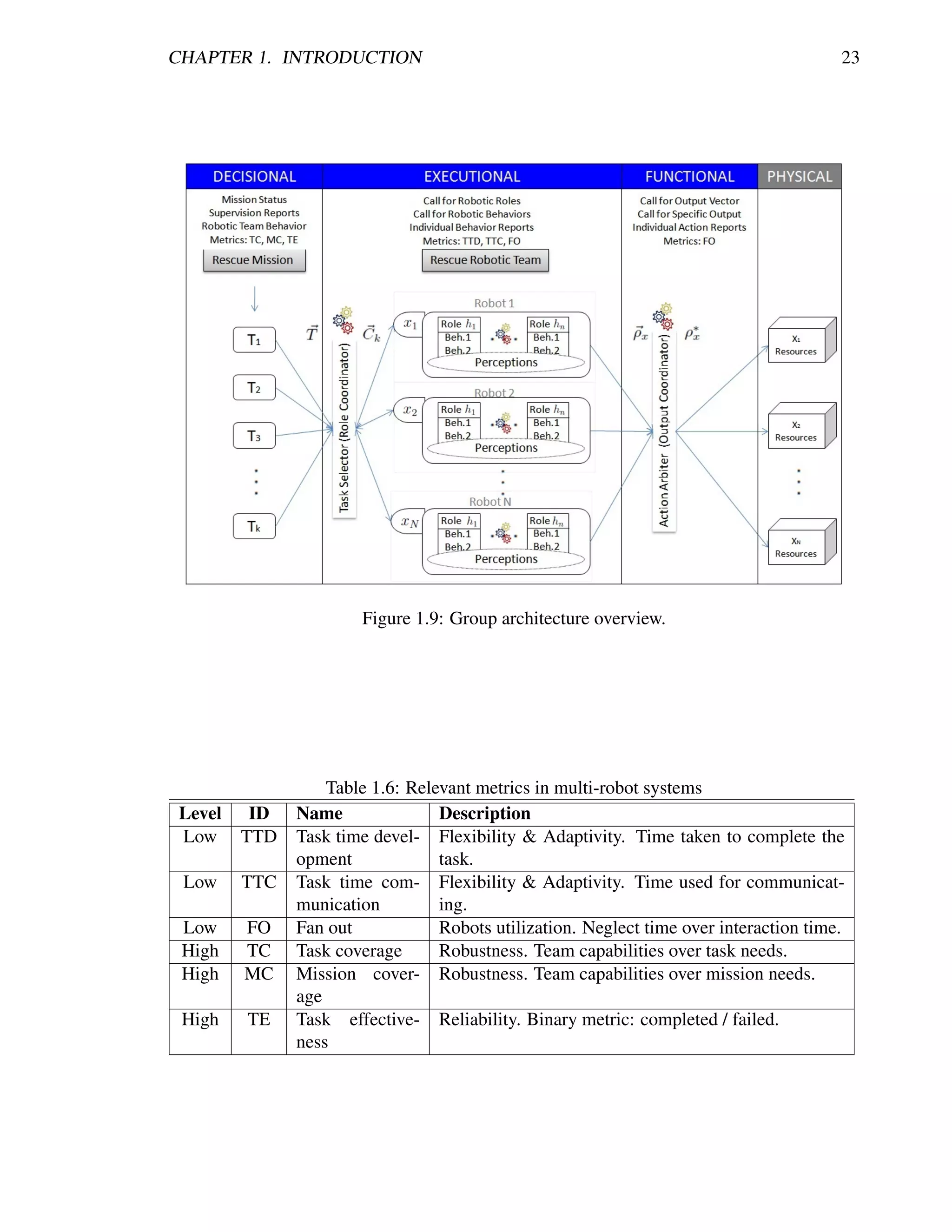
![CHAPTER 1. INTRODUCTION 24
enable us to code more efficiently in a well structured fashion. For a complete description on
how they work and MSRDS functionality refer to [70].
In that way, Figure 1.10 shows the basic unit of representation of the infrastructure for
organizing the MRS in the service-oriented approach. Every element there such as system,
subsystem and components; are intended to work as a service or group of services (applica-
tion). The complete description on its features and elements is presented in Chapter 3. For
now it is worth to mention that important aspects on the proposed architecture include:
• JAUS-compliant topology leveraging a clear distinction between levels of competence
(individual robot (subsystem) and robotic team (system) intelligence) and the simple
integration of new components and devices [106].
• Easy to upgrade, share, reuse, integrate, and to continue developing.
• Robotic platform independent, mission/domain independent, operator use independent
(autonomous and semi-autonomous), computer resource independent, and global state
independent (decentralized).
• Time-suitable communications with one-to-many control capabilities.
• Manageability of code heterogeneity by standardizing a service structure.
• Ease of integrating new robots to the network by self-identifying without reprogram-
ming or reconfiguring (self-discoverable capabilities)
• Inherent negotiation structure where every robot can offer its services for interaction
and ask for other robots’ running services.
• Fully meshed data interchange for robots in the network
• Capability to handle communication disruption where a disconnected out-of-communication-
range robot can resynchronize and continue communications when connection is recov-
ered (association/dissociation).
• Easily extended in accordance to mission requirements and available software and hard-
ware resources by instantiating the current elements.
• Capability to have more interconnected system elements each with different level of
functionality leveraging distribution, modularity, extendibility and scalability features.
1.4.3 Testbeds Overview
For demonstrating the feasibility of the solution proposed herein simulations in MSRDS and
real implementations results using research academical robotic platforms are included. Even
though Chapter 4 refers the complete detail on every test, here it is worth to mention the
general experimentation idea. This idea concerns multiple unmanned ground vehicles nav-
igating in maze-like arenas representing disasters aftermath scenarios. Their main purpose
is to gather information from the environment and map it to a central station. Thus testing](https://image.slidesharecdn.com/dtc-phd-thesis-finalversion-121215102213-phpapp01/75/PhD-Thesis-Coordination-of-Multiple-Robotic-Agents-for-Disaster-and-Emergency-Response-42-2048.jpg)
![CHAPTER 1. INTRODUCTION 25
Figure 1.10: Service-oriented group architecture.
the architecture for coupling the MRS, validating behaviors and coordinating simultaneous
triggered actions are our main tests. General assessment and deliberation on the type of aid to
give to an entity (victim, hazard or endangered kin) as well as complete rounds of coordinated
search and rescue operations are out of the scope of this work.
1.5 Main Contributions
According to [182], tools and equipment are a key aspect for successful search and rescue
operations, but they are usually disaster-specific needs. So, it is outside our scope to gen-
erate such an specific robotic team, instead we focus in a broader approach of coordinated
navigation, assuming we will be capable of implementing the same strategy regardless of the
robotics resources, which are very particular to each specific disaster. It is important to re-
member that the attractiveness of robots for disasters resides from their potential to extend the
senses of the responders into the interior of the rubble or through hazardous materials [204],
thus implying the need for navigating.
So the principal benefit of the project resides in the expectations of robotics applied in
disastrous events and the study of behavior emergence in rescue robotic teams. More specifi-
cally, the focus is to find and test the appropriate behaviors for multi-robot systems addressing
a disaster scenario, in order to develop an strategy for choosing the best combination of roles,
behaviors and actions (RBA) for mission accomplishing. So, we can refer the main contribu-
tions in the following list:
• USAR modularization leveraging local perceptions and mission decomposition into
subtasks concerning specific role, behaviors and actions.
• Primitive and composite service-oriented behaviors fully described, decomposed into
robotic actions, and organized by roles for addressing USAR operations.](https://image.slidesharecdn.com/dtc-phd-thesis-finalversion-121215102213-phpapp01/75/PhD-Thesis-Coordination-of-Multiple-Robotic-Agents-for-Disaster-and-Emergency-Response-43-2048.jpg)
![Chapter 2
Literature Review – State of the Art
“So even if we do find a complete set of basic laws, there will still be in the years
ahead the intellectually challenging task of developing better approximation
methods, so that we can make useful predictions of the probable outcomes in
complicated and realistic situations.”
– Stephen Hawking. (Theoretical Physicist)
C HAPTER O BJECTIVES
— What robots do in rescue missions.
— Which are the major software contributions.
— Which are the major hardware contributions.
— Which are the major MRS contributions.
— How contributions are being evaluated.
A good start point when looking for a solution is to identify what has been done, the
state of the art and the worldwide trends around the problem of interest. In such way, cur-
rent technological innovations are important tools that can be used to improve disaster and
emergency response and recovery. So, knowing what technology is available is crucial when
trying to enhance emergency management. The typical technology that is implemented for
these situations includes [182, 267]:
• Radar devices such as Doppler radar for severe weather forecasting and microwaves for
detecting respiration under debris.
• Traffic signal preemption devices for allowing responders to arrive without unnecessary
delay.
• Detection equipment for determining present mass destruction weapons.
• Listening devices and extraction equipment for locating and removing victims under
the debris including acoustic probes for listening to sound from victims.
• Communication devices such as amateur (ham) radios for sharing information when
other communication systems fail. Also, equipment as the ACU-1000 for linking in
a single real-time communication system all the present mobile radios, cell phones,
satellite technology and regular phones.
28](https://image.slidesharecdn.com/dtc-phd-thesis-finalversion-121215102213-phpapp01/75/PhD-Thesis-Coordination-of-Multiple-Robotic-Agents-for-Disaster-and-Emergency-Response-46-2048.jpg)
![CHAPTER 2. LITERATURE REVIEW – STATE OF THE ART 29
• Global positioning systems (GPS) for plotting damage and critical assets.
• Video cameras and remote sensing devices such as bending cameras head and light
with telescopic stick or cable for search under rubble, and infrared cameras for human
detection by means of thermal imaging; for providing information about the damages.
• Personal digital assistants (PDAs) and smartphones for communicating via phone, e-
mail or messaging in order to contact resources and schedule activities.
• Geographic information systems (GIS) for organizing and accessing spatial informa-
tion such as physical damage, economic loss, social impacts, location of resources and
assets. Also, equipment as the HAZUS for analysing scientific and engineering infor-
mation with GIS in order to estimate the hazard-related damage including shelter and
medical needs.
• Variety of tools such as pneumatic jacks for lifting structures, spreader hydraulic tools
for opening narrow gaps, air/engine tools for cutting structures, jack hammers for drilling
holes in concrete structures.
• Teleoperated robots such as submarine vehicles for underwater search, ground vehicles
to capture victims, ground vehicles for searching fire, ground vehicles for remote fire
extinguishing, and air vehicles for video streaming.
Therefore, we can refer that different sensing and communication devices are being im-
plemented by human rescuers and mobile technology in order to reduce the impact of disas-
trous events. Also, rescue teams are capable of using more technological tools than before be-
cause of lower costs of computers, software, and other equipment. Thus, this chapter presents
information on the incorporation of robotic technology for disaster response including: major
addressed problems for mobile robots in disasters, main rescue robotic software and hardware
contributions, most relevant teams of rescue robots, important tests and real implementations,
and the international standards achieved until today.
2.1 Fundamental Problems and Open Issues
Intending to implement mobile robots in disaster scenarios imply a variety of challenges that
must be addressed not only from a robotics perspective but also from some other disciplines
such as artificial intelligence and sensor networking. At hand, having a MRS for collabora-
tively assisting a rescue mission implies several challenges that are consistent among different
application domains for which a generic diagram is presented in Figure 2.1. As can be seen,
the main problems that arise reside at the intersection of control, perception and communica-
tion, which are responsible for attaining the adaptivity, networking and decision making that
will provide the capabilities for efficient operations [150].
Being more precise, concerning this work’s particular implementation domain it is worth
to describe the structure of a typical USAR scenario in order to better understand the situa-
tion. An illustration of a USAR scenario is presented in Figure 2.2. It can be appreciated that
through time solution is being addressed in three main approaches: robots and systems, simu-
lation and human responders. Each of them represent a tool for gathering more data from the](https://image.slidesharecdn.com/dtc-phd-thesis-finalversion-121215102213-phpapp01/75/PhD-Thesis-Coordination-of-Multiple-Robotic-Agents-for-Disaster-and-Emergency-Response-47-2048.jpg)
![CHAPTER 2. LITERATURE REVIEW – STATE OF THE ART 30
Figure 2.1: Major challenges for networked robots. Image from [150].
incident in order to record and map it on to a central station (usually a GIS) for better decision
making and more efficient search and rescue operations. Also, each of them intends to provide
parallel actions that can reduce operations time, reduce risks of humans, prevent secondary
damage, and raise the survival rate. Particularly, robots and systems are expected to improve
the capability of advanced equipment and the method of USAR essentially by complement-
ing human abilities and supporting difficult human tasks with the mere intention to empower
responders’ ability and efficiency [267, 268]. According to [204], these expectations imply
previously described robotic applications such as search, reconnaissance and mapping, rubble
removal, structural inspection, in-situ medical assessment and intervention, sensitive extrica-
tion and evacuation of victims, mobile repeaters, humans’ surrogates, adaptively shoring, and
logistics support. For complete details refer to [268].
Figure 2.2: Typical USAR Scenario. Image from [267].
Moreover, inside the USAR scenario robots are intended to operate at the hot zone of the
disaster. Typically in the US, the hot zone is the rescue site in which movement is restricted](https://image.slidesharecdn.com/dtc-phd-thesis-finalversion-121215102213-phpapp01/75/PhD-Thesis-Coordination-of-Multiple-Robotic-Agents-for-Disaster-and-Emergency-Response-48-2048.jpg)
![CHAPTER 2. LITERATURE REVIEW – STATE OF THE ART 31
(confined spaces), there is poor ventilation, is noisy and wet, and it is exposed to environmen-
tal conditions such as rain, snow, CBRNE materials, and natural lightning conditions [196].
Figure 2.3 shows an image taken from the WTC Tower 2 with a robot in it for demonstrating
the challenges imposed by the rubble and the difficulties for victim recognition.
Figure 2.3: Real pictures from the WTC Tower 2. a) shows a rescue robot within the white
box navigating in the rubble; b) robots-eye view with three sets of victim remains. Image
edited from [194] and [193].
So, based on the general challenge of developing an efficient MRS for disaster response
operations and on the particularities concerning networked robots and the typical USAR sce-
nario we are able to state the major addressed issues for robotic search and rescue. Each
challenge is described below.
Control. As previously referred, the platform control and activity control are a chal-
lenging task because of the mechanical complexities of the different UxVs and the
characteristics of the environments [204]. This challenging task such as motion con-
trol have been being developed for the purpose of improving communications [132],
localization [119, 144, 286], information integration [165], deployment [76, 144], cov-
erage/tracking [140, 129, 160, 149, 39, 89, 226, 7, 248], cooperative reconnaissance
[285, 58, 130, 101, 131, 290, 205, 100, 164], cooperative manipulation [262], and coor-
dination of groups of unmanned vehicles [199, 112, 202, 119, 120, 271, 93, 167], among
other tasks. An overview of all the issues to control a MRS can be found at [130].
Communications. In order to enhance rescuers sensing capabilities and to record gath-
ered information on the environment robots rely on real-time communications either
through tether or wireless radio links [204]. At a lower level, communications enable for
state feedback of the MRS, which exchanges information for robot feedforward control;
at a higher level, robots share information for planning and for coordination/cooperation
control [150]. The challenge resides in that large quantities of data such as image and
range finder are necessary for enough situation awareness and efficient task execution,
but there is typically a destroyed communication infrastructure and ad hoc networks and
satellite phones are likely to become saturated [204, 268]. Also, implementing lossy
compression reduces bandwidth, but the cost is losing information critical to computer
vision enhancements and artificial intelligence augmentation. Moreover, using wireless
communications demands for encrypted video so as to not be intercepted by a news
agency, violating a survivors privacy [194]. Examples of successful communication](https://image.slidesharecdn.com/dtc-phd-thesis-finalversion-121215102213-phpapp01/75/PhD-Thesis-Coordination-of-Multiple-Robotic-Agents-for-Disaster-and-Emergency-Response-49-2048.jpg)
![CHAPTER 2. LITERATURE REVIEW – STATE OF THE ART 32
networks among multiple robots can be found in [119, 76, 130, 131]. However, im-
plementations in disaster scenarios haven’t demonstrated solid contributions but rather
point to promising directions for future work in hybrid tether-wireless communication
approaches allowing for reducing computational costs, enough bandwidth, latency and
stability. It is worth to mention that in the WTC disaster just one robot was intended to
be wireless and it was lost and never recovered [194].
Sensors and perceptions. According to [196] sensors for rescue robots fall into two
main categories: control of the robot and victim/hazards identification. For the first
category, sensors must permit control of the robot through confined, cluttered spaces;
perhaps localization and pose estimation sensors are the greatest challenge. Thus, small-
sized range finders are needed in order to attain good localization and mapping results,
and to aid odometry and GPSs sensors, which are not always available or sufficient.
Relevant works in this category can be found in [130, 33]. On the other hand, victim
and hazards detection and identification requires specific sensing devices and algorithms
for which research development is being carried out. Essentially, there is the need for
a sensor that can perceive victims obscured by rubble and another to refer the victim’s
status. For this, smaller and better sensors are not sufficient but improvements in sens-
ing algorithms are also needed [204]. At this time, autonomous detection is considered
well beyond the capabilities of computer vision so humans are expected to interpret
all sensing data in real-time and it is still difficult (refer to Figure 2.3). Nevertheless,
it has been demonstrated that video cameras are essential not only for detection pur-
poses but for navigational issues and teleoperation means [196]. Color cameras have
been successfully used in aiding to find victims [194] and black and white cameras for
structural inspection [203]. Also, lightning for the cameras and special purpose video
devices such omni-cams or fish-eye cameras, 3D range cameras and forward looking in-
frared (FLIR) miniature cameras for thermal imaging are of significant importance but
may not be always useful and typically they are large and noisy (at WTC disaster col-
lapsed structures where too hot that FLIR readings were irrelevant [194]). Moreover,
other personal protection sensors are being implemented such as small-size sensors
for CBRNE materials, oxygen, hydrogen sulfide, methane, and carbon dioxide sensors,
which can be beneficial in preventing rescue workers from also becoming victims [196].
Additionally, rapid sampling, distributed sensing and data fusing are important prob-
lems to be solved [268]. Relevant works towards USAR detection tasks can be found
in [163, 90, 246, 130, 116, 161], among others. In short, new developments for smaller
and robust sensing devices is a must. Also, interchangeable sensors between robotic
platforms are desired and thus standards and cost-reduction are needed. Here comes the
possibility for implementing artificial intelligence so as to take advantage from inex-
pensive sensors in order to improve problems such as the lack of depth perception, hard
to interpret data, lack of peripheral vision or feedback, payload support, unclear planar
laser readings, among others.
Mobility. According to [204] the problem of mobility remains a major issue for all
modalities of rescue robots (aerial, ground, underground, surface and underwater) but
specially for ground robots. It states that the essential challenge resides in the com-
plexity of the environment, which is currently lacking of a useful characterization of](https://image.slidesharecdn.com/dtc-phd-thesis-finalversion-121215102213-phpapp01/75/PhD-Thesis-Coordination-of-Multiple-Robotic-Agents-for-Disaster-and-Emergency-Response-50-2048.jpg)
![CHAPTER 2. LITERATURE REVIEW – STATE OF THE ART 33
rubble to facilitate actuation and mechanical design. In general, robotic platforms need
to be small to fit through voids but at the same time highly mobile, flexible, stable and
self-righting (or better highly symmetrical with no side up). Also, real implementations
have shown the need for not losing traction, tolerating moderated vertical drops, and
sealed enclosures for dealing with harsh conditions [196, 194]. With these character-
istics in mind, robots are expected to exhibit efficiency in their mechanisms, control,
and sensing; so as to improve navigational performance such as speed and power econ-
omy [268]. Most relevant robotic designs and mobility features for search and rescue
are detailed in Section 2.3.
Power. Since implementation domain implies inherent risks, flammable solutions such
as combustion are left apart and electrical battery power is preferred. According to [204],
the most important aspects concerning the power source are: robot payload capabilities
and location providing good vehicle stability and ease of replacing without special tools.
Many batteries exist that can be used and the appropriate one must be particular of the
robotic resources. So, choosing the right one and knowing the batteries state of the art
is the main challenge.
Human-robot interaction. Rescue robots interact with human rescuers and with hu-
man victims, they are part of a human-centric system. According to [68, 204], this
produces four basic problems: 1)human-to-robot ratio for safe and reliable operations,
where nowadays a single robot requires multiple human operators; 2)humans teleop-
erating robots must be highly prepared and trained, this is a scarce resource in a re-
sponse team; 3)user interfaces are insufficient, non friendly and difficult to interpret;
and 4)there is the need for controlling the robots in order to approach humans in an
’affective robotics’ approach so as to seem helpful. These four problems determine if a
robot can be used in a disaster scenario such as the case of a robot at the WTC that was
rejected because of the complexity of its interface [194]. Perhaps these implications and
the desired semi-autonomy to augment human rescuers abilities motivated the RoboCup
Rescue to suggest the needed information for a user interface: a) the robot’s perspec-
tive plus perceptions that enhance the impression of telepresence; b) robot’s status and
critical sensor information; and c) a map providing the bird-eye view of the locality.
Moreover, relevant guidelines have been proposed such as in [292]. The thing is that
the human-robot interaction must provide a way of cooperation with an interface that
reduces fatigue and confusion in order to achieve a more intelligent robot team [196].
What is more, acceptance of rescue robots within existing social structure must be en-
couraged [193].
Localization and data integration. As previously referred a robot must localize itself
in order to operate efficiently and this is a challenging task in USAR missions. In ad-
dition to the instrumentation problems, computation and robustness in the presence of
noise and affected sensor models are basic for practical localization and data integration.
As we had stated in USAR GIS mapping is necessary to use information gathered by
multiple robots and systems and come up with a strategy and decision making process,
so it is of crucial importance to have an adequate distributed localization mechanism](https://image.slidesharecdn.com/dtc-phd-thesis-finalversion-121215102213-phpapp01/75/PhD-Thesis-Coordination-of-Multiple-Robotic-Agents-for-Disaster-and-Emergency-Response-51-2048.jpg)
![CHAPTER 2. LITERATURE REVIEW – STATE OF THE ART 34
and to deal with particular problems that arise when robot networks are used for identi-
fying, localizing, and then tracking targets in a dynamic setting [150]. Field experience
is needed for determining when to consider sensor readings as reliable or it is better
to discard data or use a fusing technique (typically Kalman filtering [288]). Relevant
developments can be found in [130, 33].
Autonomy. This problem is perhaps the ‘Holy Grail’ for robotics and artificial intelli-
gence as stated by Birk and Carpin in [33]. It is in the middle between the ideal au-
tonomous robot rescue team that would traverse a USAR scenario, locate victims, and
communicate with the home base [196]; and the unrealistic and undesirable solution
system for disaster response [194]. In a broad manner it is accepted that a greater de-
gree of autonomy with improved sensors and operator training will greatly enhance the
use of robots at USAR operations, but an issue of trust from the human rescuers must be
solved first with further successful deployments and awareness of robotic tools to assist
the rescue effort [37, 194, 33]. That is the main reason why all robots in the first real
implementation at WTC were teleoperated as well as those in the latest nuclear disas-
ter in Fukushima. In fact, in [194] were demonstrated some forms of semiautonomous
control for USA, but they were not allowed to use it, however they stated that it was
more likely to achieve autonomous navigation with miniaturized range sensors than au-
tonomous detection of victims, which represents very challenging issues for computer
vision under unstructured lightning conditions. So, for autonomous navigation typical
path planning algorithms, path following and more methodical algorithms might not
be as helpful because of the diversity of the voids. Therefore, from a practical soft-
ware perspective, autonomy must be adjustable (i.e., the degree of human interaction
varies) so that rescuers can know what is going on a take appropriate override com-
mands, while robots serve as tools enhancing rescue teams capabilities [196]. What is
more, research groups are working towards the system intelligence that can be fitted in
on-board processing units since communications may be intermittent or restricted.
Cooperation. As the mission is challenging enough, an heterogeneous solution to cover
disaster areas comes to be an invaluable tool. Robots, humans and other technological
systems must be used in a cooperative and collaborative manner so as to achieve ef-
ficient operations. Main developments concerning cooperation can be found in [199,
112, 202, 119, 120, 271, 93, 167, 58, 33, 130, 101, 131, 290, 222, 205, 100, 164].
Performance metrics. Until today there are no standardized metrics because evalua-
tion of rescue robots is complex. On one hand, disaster situations are different case
by case and this represents no simple characterization among them leaving no room
for performance comparison [268]. On the other hand, robots and their missions are
also different and are highly dependant on human operators. So, for now it has been
proposed to evaluate post-mission results such as video analysis for missed victims and
avoidable collisions [194], and disaster ad hoc qualitative metrics [204]. It is worth to
refer that RoboCup Rescue evaluates quantitative metrics such as number of victims
found [19], traversing time [295] and map correctness [155, 6], but these metrics do not
capture the value of a robot in establishing that there are no survivors or dangers in a
particular area. Thus, metrics for measuring performance remain undefined.](https://image.slidesharecdn.com/dtc-phd-thesis-finalversion-121215102213-phpapp01/75/PhD-Thesis-Coordination-of-Multiple-Robotic-Agents-for-Disaster-and-Emergency-Response-52-2048.jpg)
![CHAPTER 2. LITERATURE REVIEW – STATE OF THE ART 35
Components performances. According to [268], research must be done in high-power
actuators, stiff mechanisms, sensor miniaturization, light weight, battery performance,
low energy consumption, and higher sensing ability (reliable data). These important
component technologies are the essential features that provide reliability, environment
resistance, durability, water-proof, heat-proof, dust-proof, and anti-explosion; all of
which are crucial for in-disaster operations.
So, we can conclude at this point that the research field of rescue robotics is large,
with many different research areas open for investigation. Also, it can be deducted from
the majority of the work in this area that mobile robots are an essential tool within USAR
and their utilisation will increase in the future [37, 194, 33, 204, 268]. For now they have
several problems to be solved and are not ready because of size needs, insufficient mobility,
situation awareness, wireless communications and sensing capabilities. For example UAVs
have been successfully deployed for gathering overview information of disaster but they lack
of important aspects such as the robustness against bad weather, obstacles such as birds and
electric power lines, wireless communication, limitation of payload and aviation regulation.
On the other hand, UGVs successfully deployed for finding victims need the human operator
to help for deciding if a victim is detected and even though they are teleoperated, they still
lack of good mobility and actuation. Problems are about the same among different modalities
of robots and Figure 2.4 depicts the most important ones. The important thing is that there
is a clearly open path towards researching and pushing forward worldwide trends such as
ubiquitous systems to have information on security sensors, fire detectors, among others; and
miniaturization of devices in order to reduce the robotic platforms physical, computational,
power, and communication constraints so as to facilitate autonomy.
Figure 2.4: Typical problems with rescue robots. Image from [268].
Last but not least, it is worth to take a look at the following list concerning the most
relevant research contributions in rescue robotics. They are listed according to the leader
researcher including the developments done since 2000 until today. After the list, Section 2.2
presents the description of the most relevant software contributions.](https://image.slidesharecdn.com/dtc-phd-thesis-finalversion-121215102213-phpapp01/75/PhD-Thesis-Coordination-of-Multiple-Robotic-Agents-for-Disaster-and-Emergency-Response-53-2048.jpg)
![CHAPTER 2. LITERATURE REVIEW – STATE OF THE ART 36
• Robin Murphy, Texas A&M, Center for Robot Assisted Search And Rescue (CRASAR).
– understandings of in-field USAR [69];
– mobile robots opportunities and sensing and mobility requirements in USAR [196];
– team of teleoperated heterogeneous robots for a mixed human-robot initiative for
coordinated victim localization [199];
– recommendations and experiences towards the RoboCup Rescue and standardiza-
tion of robots potential tasks in USAR [198, 197];
– experiences in mobility, communications and sensing at the WTC implementa-
tions [194];
– recommendations and synopsis of HRI based on the findings, from the post-hoc
analysis of 8 years of implementations, that impact the robotics, computer science,
engineering, psychology, affective and rescue robotic fields [68, 193, 32];
– novel taxonomy on UGV failures according to WTC implementations and other 9
relevant USAR studies [65];
– multi-touch techniques and devices validation tests for HRI and teleoperation of
robots in USAR [186, 185];
– survey on rescue robotics including robot design, concepts, methods of evaluation,
fundamental problems and open issues [204];
– survey and experiences of rescue robots for mine rescue [200, 201];
– robots that diagnose and help victims with simple triage and rapid treatment (start)
methods concerning mobility, respiration, blood pressure and mental state [80];
– underwater and aerial after collapse structural inspections including damage foot-
print and mapping of the debris [228, 203];
– study of the domain theory and robotics applicability and requirements for wild-
land firefighting [195];
– deployment of different robots for aiding in the Fukushima nuclear disaster [237].
• Satoshi Tadokoro, Tohoku University, Tadokoro. Laboratory.
– understandings of the rescue process after the Kobe earthquake, explaining the
opportunities for robots [269]
– understandings of the simulation, robotic, and infrastructure projects of the RoboCup
Rescue [270];
– design of special video devices for USAR [123] and implementation in the Fukushima
nuclear disaster [237];
– robot hardware and control software design for USAR [215, 61];
– in-field demonstration experiments with robots training along with human first
responders [276];
– guidelines for human interfaces for using rescue robots in different modalities [292];](https://image.slidesharecdn.com/dtc-phd-thesis-finalversion-121215102213-phpapp01/75/PhD-Thesis-Coordination-of-Multiple-Robotic-Agents-for-Disaster-and-Emergency-Response-54-2048.jpg)
![CHAPTER 2. LITERATURE REVIEW – STATE OF THE ART 37
– exploration and map building reports from RoboCup Rescue implementations [205];
– complete book on rescue robots, robotic teams for USAR, demonstrations and real
implementations, and the unsolved problems and future roadmap [267];
– survey on the advances and contributions for USAR methods and rescue robot
designs including evaluation metrics and standardizations, and the open issues
and challenges [268].
• Fumitoshi Matsuno, Kyoto University, Matsuno Laboratory.
– development of snake-like rescue robot platform [142];
– RoboCup Rescue experiences and recommendations on the effective multiple robot
cooperative activities for USAR [246];
– robotic rescue platforms for USAR operations [245, 181];
– development of groups of rescue robot development platforms for building inspec-
tion [141];
– development of on-rubble rescue teams using tracked robots [180, 189];
– implementation of rescue robots in the Fukushima nuclear disaster [237];
– information infrastructures and ubiquitous sensing and information collection for
rescue systems [14];
– generation of topological behavioral trace maps using multiple rescue robots [164];
– the HELIOS system for specialized USAR robotic operations [121].
• Andreas Birk, Jacobs University (International University Bremen), Robotics Group.
– individual rescue robot control architecture for ensuring semi-autonomous opera-
tions [34];
– understandings of software component reuse and its potential for rescue robots [145];
– merging technique for multiple noisy maps provided by multiple rescue robots [66];
– USARSim, a high fidelity robot simulation tool based on a commercial game en-
gine, and intended to be the bridge between the RoboCup Rescue Simulation and
Real Robot Leagues [67, 18, 17, 20];
– multiple rescue robots exploration while ensuring to keep every unit inside com-
munications range [239];
– cooperative and decentralized mapping in the RoboCup Rescue Real Robot League
and in USARSim implementations [33, 225];
– human-machine interface (HMI) for adjustable autonomy in rescue robots [35];
– mechatronic component design for adjusting the footprint of a rescue robot so as
to maximize navigational performance [85];
– complete hardware and software framework for fully autonomous operations of a
rescue robot implemented in RoboCup Rescue Real Robot League [224];](https://image.slidesharecdn.com/dtc-phd-thesis-finalversion-121215102213-phpapp01/75/PhD-Thesis-Coordination-of-Multiple-Robotic-Agents-for-Disaster-and-Emergency-Response-55-2048.jpg)
![CHAPTER 2. LITERATURE REVIEW – STATE OF THE ART 38
– efficient semi-autonomous human-robot cooperative exploration [209]
– teleoperation and networking multi-leveled framework for the heterogeneous wire-
less traffic for USAR [36].
• Other relevant researchers, several institutions, several laboratories.
– an overview of rescue robotics field [91];
– survey on rescue robots, deployment scenarios and autonomous rescue swarms
including an analysis of the gap between RoboCup Rescue and the real world [261,
212];
– metrics and evaluation methods for the RoboCup Rescue and general multi-robot
teams [254, 143];
– rescue robot designs [282, 40, 158, 265, 8, 266, 84, 277, 187, 211, 216, 249, 87,
151, 252];
– system for continuous navigation of rescue teams [9];
– a multi-platform on-board system for teleoperating different modalities of un-
manned vehicles [108];
– multi-robot systems for exploration and rescue including fire-fighting, temperature
collection, reconnaissance and surveillance, target tracking and situational aware-
ness [242, 140, 129, 76, 119, 149, 58, 120, 132, 144, 130, 101, 229, 131, 39, 290,
206, 98, 7, 226, 248, 126, 168, 100, 13, 57, 256, 232, 10, 43, 112, 295, 253, 60,
240, 114, 259, 280, 92, 169, 294, 25];
– useful coordination and swarm intelligence algorithms [241, 75, 74, 78, 112, 78,
79, 271, 93, 89, 166, 167, 161, 162, 208, 118, 5].
2.2 Rescue Robotics Relevant Software Contributions
This section is intended to provide information on some of the most relevant software de-
velopments that have contributed towards the use of robotic technology for urban search and
rescue. It is important to clarify that there have been plenty of successful algorithms for
working with multiple robots in several application domains that could be useful for rescue
implementations. Nevertheless, in spite of these indirect contributions, information herein
resides essentially in solutions intended directly for the rescue domain and related tasks.
2.2.1 Disaster Engineering and Information Systems
Perhaps the most basic contributions towards using robotics to mitigate disasters reside in the
identification of the factors that are involved in a rescue scenario. This provides a way to
understand what we are dealing with and what must be taken into consideration for proposing
solutions. Also, this disaster analysis creates a path for developing more precise tools such
as experts systems and template-based methodologies for information management and task
force definition.](https://image.slidesharecdn.com/dtc-phd-thesis-finalversion-121215102213-phpapp01/75/PhD-Thesis-Coordination-of-Multiple-Robotic-Agents-for-Disaster-and-Emergency-Response-56-2048.jpg)
![CHAPTER 2. LITERATURE REVIEW – STATE OF THE ART 39
In [83] an appropriate disaster engineering can be found based on the 2004 Asian
Tsunami. This particular disaster presented the opportunity to develop a profound analysis
not only because of its large damage but also because at the beginning of the disaster response
operations everything was carried out with an important lack of organization. Every country
tried to help in their own way resulting in a sudden congregation of large amounts of resources
that caused delays, provisions piling up, and aid not reaching victims. The present lack of co-
ordination among the various parties also provoked tensions between the in-site rescue teams,
which were different at elemental human levels such as cultural, racial, religious, political and
other sensitivities important when conducting a team effort. Fortunately, the ability to adapt
and improvise plans on the fly permitted the isolated countries to get connected in a network
of networks with assigned leaders coordinating the efforts. This turned operations more struc-
tured and aid could reach the victims more quickly. So, a lesson was learned showing up that
even with limited resources a useful contribution can be made if the needs are well-identified
and the rescue efforts are properly coordinated. This resulted in a so called Large Scale Sys-
tems Engineering framework concerning the conceptualization and planning of how a disaster
relief could be carried out. The most important is the definition of the most critical constraints
affecting a disaster response shown in Table 2.1.
Accordingly, in order to address constraints such as time, environmental, information,
and even people, different damage assessment systems have been created. The importance
of determining the extent of damage to life, property, the environment, resides in the priori-
tization of relief efforts in order to define a strategy that can match our intentions for raising
survival rate and reducing further damage. In [81], an expert system to assess the damage for
planning purposes is presented. This software helps to prepare initial damage maps by fusing
data from Satellite Remote Sensing (SRS) and Geographic Information Systems. A typical
technique consist in visual change algorithms that compare (subtraction, ratio, correlativity,
comparability. . . ) pre-disaster and post-disaster satellite images, but authors created an expert
system consisting in an human expert, a knowledge base, an inference engine based on deci-
sion trees, and a user interface. In that way, using a dataset for experimentation the system
was fed with a set of rules such as “IF (IMAGE CHANGE=HIGH) AND (BUILDING DEN-
SITY=HIGH) THEN (PIXEL=SEVERELY DAMAGED AREA” and obtained over 60% of
accuracy for determining the real damage extent in all cases. The most important of this kind
of developments is the additional information that could be used for planning and structuring
information.
In addition, relevant information structures have been defined in order to organize data
for developing more efficient disaster response operations. These structures are in fact a
template-based information system, which is expected to facilitate preparedness and impro-
visation by first gathering information from the ravaged zone, and subsequently provide a
protocol for coordinating rescue teams without compromising their autonomy and creativity.
A template that is consistent among different literature is shown in Figure 2.5 [156, 56]. It
matches different characteristics of the typical short-lasting (ephemeral) teams that emerge in
a disaster scenario with communication needs that must be met in order for efficient opera-
tions. Concerning the boundaries and membership characteristics, which refer to members
entering and exiting different rescue groups, information is needed on what they should com-
municate among the groups, where they are, why and when they leave a group, and who to
communicate to. In the case of leadership, several leaders may help for coordination among](https://image.slidesharecdn.com/dtc-phd-thesis-finalversion-121215102213-phpapp01/75/PhD-Thesis-Coordination-of-Multiple-Robotic-Agents-for-Disaster-and-Emergency-Response-57-2048.jpg)
![CHAPTER 2. LITERATURE REVIEW – STATE OF THE ART 40
Table 2.1: Factors influencing the scope of the disaster relief effort from [83].
Limiting Factors Important questions to consider
Primary Boundaries
How much time do we have to scope the efforts?
Time What must be done to minimize the time needed to
aid the survivors?
What is the current political relationship between the
affected nation and the aiding organizations?
Political What is the current internal political state (potential
civil/social unrest) of the affected country?
How much assistance is the affected government will-
ing to accept?
External Limitations
What are the causes of the disaster?
What is the extent of the damage due to the disaster?
Environmental What are the environment conditions that would limit
the relief efforts (e.g. proximity to helping country,
accessibility to victims)?
Information How much information on the disaster do we have?
How accurate is the information provided to us?
Internal Limitations
How can technology enhance relief efforts?
What extent and depth of training does the response
team have?
Capability How far can this training be converted to relevant skill
sets to carry out the rescue efforts?
What is the extent of the coordination effort required?
What is the range and extent of the critical resources
present allocated to the response team?
How are the resources contributing to the overall re-
lief effectiveness in terms of reliability, maintainabil-
ity, supportability, dependability and capability?
People What is the state of the victims?
Resources What are the perceptions of the public of the affected
country and aiding countries and organizations with
regards to the disaster?
How are recent world developments (e.g. frequencies
of events, economy climate, social relationships with
the victims) shaping the willingness of people to as-
sist in the relief efforts?](https://image.slidesharecdn.com/dtc-phd-thesis-finalversion-121215102213-phpapp01/75/PhD-Thesis-Coordination-of-Multiple-Robotic-Agents-for-Disaster-and-Emergency-Response-58-2048.jpg)
![CHAPTER 2. LITERATURE REVIEW – STATE OF THE ART 41
different groups so they need to inform who to communicate to and what they are doing.
Then, the networking characteristic or organizational morphology must adapt to the changing
operations requirements so they must deal with what to report just before changing in order
not to lose focus and strategy. Work, tasks and roles primarily concern where they should
be done and why. Then, activities serve as organizational form and behavior triggered by
rules of procedures and thus dealing with the what to do and who to report factors. Next, the
ephemeral is concerned in completing the task, rather than adopting the best approach or even
a better method, so, the only way to quickly convert decision into action is to act on an ad
hoc basis considering who to communicate to, how to develop actions and how to decompose
activities. As for memory, it is practically impossible for rescue groups to replicate or base
current operations on previous experiences, but there is an opportunity for using knowledge
for future reference in order to develop best practices on how to act and activities decomposi-
tion. The final characteristic is intelligence, which is very restricted for rescue teams because
they intervene and act on the ground with only partial information or local intelligence crucial
for defining what to do an when to do it. So, this mapping produces the template that has been
used in major disaster such as the WTC. Examples are shown in Figure 2.6.
Figure 2.5: Template-based information system for disaster response. Image based on [156,
56].
With this information in mind, other important contributions consider the definition of
information flow and management so as to achieve a productive disaster relief strategy. We
have stated the importance of quickly collecting global information on the disaster area and
victims buried in the debris awaiting rescue. In [14] they provide their view for ideal in-
formation collection and sharing in disasters. It is based upon an ubiquitous device called
Rescue-Communicator (R-Comm) and RFID technologies working along with mobile robots](https://image.slidesharecdn.com/dtc-phd-thesis-finalversion-121215102213-phpapp01/75/PhD-Thesis-Coordination-of-Multiple-Robotic-Agents-for-Disaster-and-Emergency-Response-59-2048.jpg)
![CHAPTER 2. LITERATURE REVIEW – STATE OF THE ART 42
Figure 2.6: Examples of templates for disaster response. Image based on [156, 56].
and information systems. The R-Comm comprises a microprocessor, a memory, three com-
pact flash slots, a voice playback module including a speaker, a voice recording module in-
cluding a microphone, a battery including a power control module, and two serial interfaces.
One of the compact flash slots is equipped with wireless/wired communication. The system
can operate for 72 h, which is the critical time for humans to survive. It is supposed to be
triggered by emergency situations (senses vibrations or voltage drop) and play recorded mes-
sages in order to seek for a human response at the microphones and send information to local
or ad hoc R-Comm networks. Then, RFID technologies are used for marking the environment
in order for the ease of mapping and recognizing which zones have been already covered and
even for denoting if they are safe or dangerous. Finally, additional information is collected
with the deployment of mobile devices such as humans with PDAs and unmanned vehicles as
rescue robots. Figure 2.7 shows a graphic representation of what is intended for information
collection using technology. Then, Figure 2.8 shows a picture of an R-Comm and Figure 2.9
shows a picture of example RFID devices used in rescue robotics experimentation. In the
end, R-Comm, RFID and mobile devices information is sent through a network into an infor-
mation system known as Database for Rescue Management (DaRuMa) in order to integrate
information and provide better situational awareness with an integrated map with different
recognition marks.
According to [210], the DaRuMa consists in a reference system that utilizes a proto-
col for rescue information sharing called Mitigation Information Sharing Protocol (MISP),
which provides functions to access and to maintain geographical information databases over
networks. Through a middleware it translates MISP to SQL in order to get SQL tables from
XML structures in a MySQL server database. The main advantage is that it is highly portable
to several OS and hardware and it is able to support multiple connections at the same time en-
abling for integrating information from multiple devices in a parallel way. Additionally, there
is a developed tool for linking the created database with the Google Earth, a popular GIS.
Figure 2.10 shows a diagram for representing how the DaRuMa system collects information
from different devices and interacts with them for communication and sharing purposes.](https://image.slidesharecdn.com/dtc-phd-thesis-finalversion-121215102213-phpapp01/75/PhD-Thesis-Coordination-of-Multiple-Robotic-Agents-for-Disaster-and-Emergency-Response-60-2048.jpg)
![CHAPTER 2. LITERATURE REVIEW – STATE OF THE ART 43
Figure 2.7: Task force in rescue infrastructure. Image from [14].
Figure 2.8: Rescue Communicator, R-Comm: a) Long version, b) Short version. Image
from [14].](https://image.slidesharecdn.com/dtc-phd-thesis-finalversion-121215102213-phpapp01/75/PhD-Thesis-Coordination-of-Multiple-Robotic-Agents-for-Disaster-and-Emergency-Response-61-2048.jpg)
![CHAPTER 2. LITERATURE REVIEW – STATE OF THE ART 44
Figure 2.9: Handy terminal and RFID tag. Image from [14].
Figure 2.10: Database for Rescue Management System, DaRuMa. Edited from [210].](https://image.slidesharecdn.com/dtc-phd-thesis-finalversion-121215102213-phpapp01/75/PhD-Thesis-Coordination-of-Multiple-Robotic-Agents-for-Disaster-and-Emergency-Response-62-2048.jpg)
![CHAPTER 2. LITERATURE REVIEW – STATE OF THE ART 45
2.2.2 Environments for Software Research and Development
We have previously mentioned the existence of the RoboCup Rescue, which stands for Sim-
ulated and Real Robot leagues. This competition has served importantly as a test bed for
artificial intelligence and intelligent robotics research. As stated in [270] it is an initiative that
intends to provide emergency decision and action support through the integration of disaster
information, prediction, planning, and human interface in the virtual disaster world where
various kinds of disasters are simulated. The Simulation League consists of a software world
of simulated disasters in which different agents interact as victims and rescuers in order for
testing diverse algorithms so as to maximize virtual disaster experience in order to use it for
the human world and perhaps reaching transparent implementations towards real disasters
mitigation. The overall concept of the RoboCup Rescue remains persistent as it is in Fig-
ure 2.11. Nevertheless the simulator has evolved into the most recent implementations using
the so called USARSim.
The USARSim is a software that has been internationally validated for robotics and
automation research. It is a high fidelity robot simulation tool based on a commercial game
engine which can be used as a bridging tool between the RoboCup Rescue Real Robot League
and the RoboCup Rescue Simulation League [67]. The main purpose is to provide an envi-
ronment for the study of HRI, multi-robot coordination, true 3D mapping and exploration of
environments by multi-robot teams, development of novel mobility modes for obstacle traver-
sal, and practice and development for real robots that will compete in the physical league.
Among the most relevant advantages are the capabilities for rendering video, representing
robot automation and behavior, and accurately representing the remote environment that links
the operator’s awareness with the robot’s behaviors. Today, the USARSim consists of sev-
eral robot and sensor models (Figure 2.12) including the possibility for designing your own
devices, and also environmental models representing different disasters (Figure 2.13) and in-
ternational standard arenas for research comparison and competition (refer section sec:stds).
Robots in the simulator are used to develop typical rescue activities such as autonomously ne-
gotiating compromised and collapsed structures, finding victims and ascertaining their condi-
tion, producing practical maps of victim locations, delivering sustenance and communications
to victims, identifying hazards, and providing structural shoring [18].
Furthermore, the USARSim is providing the infrastructure for comparing different de-
velopments in terms of score vectors [254]. The most important aspect about these vectors
is that they are based upon the high fidelity framework so that the difference between multi-
ple implementations in simulation and real robots remains minimal. As can be seen in Fig-
ure 2.14, the data collected from the sensor reading in the simulator (top) are very similar to
the ones collected from the real version (bottom). This allows researchers to be able to com-
pare almost essentially the algorithms and intelligence behind their systems trying to reach
standardized missions in which they must find victims and extinguish fires while using com-
munications and navigating efficiently.
On the other hand, according to [17] the main drawbacks reside in the ability to cre-
ate, import and export textured models with arbitrarily complicated geometry in a variety of
formats is of paramount importance, also the ideal next generation simulation engine shall
allow the simulation of tracked vehicles and sophisticated friction modelling. What is more,](https://image.slidesharecdn.com/dtc-phd-thesis-finalversion-121215102213-phpapp01/75/PhD-Thesis-Coordination-of-Multiple-Robotic-Agents-for-Disaster-and-Emergency-Response-63-2048.jpg)
![CHAPTER 2. LITERATURE REVIEW – STATE OF THE ART 46
Figure 2.11: RoboCup Rescue Concept. Image from [270].](https://image.slidesharecdn.com/dtc-phd-thesis-finalversion-121215102213-phpapp01/75/PhD-Thesis-Coordination-of-Multiple-Robotic-Agents-for-Disaster-and-Emergency-Response-64-2048.jpg)
![CHAPTER 2. LITERATURE REVIEW – STATE OF THE ART 47
Figure 2.12: USARSim Robot Models. Edited from [284, 67].
Figure 2.13: USARSim Disaster Snapshot. Edited from [18, 17].](https://image.slidesharecdn.com/dtc-phd-thesis-finalversion-121215102213-phpapp01/75/PhD-Thesis-Coordination-of-Multiple-Robotic-Agents-for-Disaster-and-Emergency-Response-65-2048.jpg)
![CHAPTER 2. LITERATURE REVIEW – STATE OF THE ART 48
Figure 2.14: Sensor Readings Comparison. Top: Simulation, Bottom: Reality. Image
from [67].](https://image.slidesharecdn.com/dtc-phd-thesis-finalversion-121215102213-phpapp01/75/PhD-Thesis-Coordination-of-Multiple-Robotic-Agents-for-Disaster-and-Emergency-Response-66-2048.jpg)
![CHAPTER 2. LITERATURE REVIEW – STATE OF THE ART 49
it should should be easy to add a new robot and to code novel components based on the avail-
able primitives and backward compatibility with the standard USARSim interface should be
assured. For the complete details on this system refer to [284].
2.2.3 Frameworks, Algorithms and Interfaces
As a barely explored research field, just a few direct contributions have been made directly to
rescue robotics but several other applications that serve for search and rescue as well as other
disaster response operations are being used in the field.
Control Architectures for Rescue Robots and Systems
Perhaps a good start point is to reference that until now there is no known single robot or
multi-robot architecture that serves as the default infrastructure for working with robot in dis-
asters. In [3], authors propose a generic architecture for rescue missions in which they divide
the control blocks according to the level of intelligence or computational requirements. At
the lowest level reside the sensors and actuators interfacing. Then, a reactive level is included
concerning basic robot behaviors for exploration and self-preservation, and essential sensing
for self-localization. Next, an advanced reactive layer is included concerning simultaneous lo-
calization and mapping (SLAM) and goal-driven navigation behaviors as well as identification
modules for target finding and feature classification. Then, at the highest level are included
the learning capabilities and the coordination of the lower levels. Each level is linked via user
interface and a communication handler. Figure 2.15 shows a representation of the architec-
ture. The relevance of this infrastructure is that it considers all the needs for a rescue scenario
with an approach independent from robotic hardware and in a well-fashioned level distribu-
tion enabling researchers to focus in particular blocks while constructing the more complex
system.
Navigation and Mapping
Concerning the navigation of mobile robots a huge amount of algorithms can be found in
literature for a wide variety of locomotion mechanisms including different mobile modali-
ties. Among the modern classic approaches there are the behavior-based works inspired by
R. Brooks research [49, 50, 51, 54, 52, 53] which lead to representative contributions that can
be summarized in Table 2.2.
Moreover, more recent research developments include works such as automated explo-
ration and mapping. The main goal in robotic exploration is to minimize the overall time
for covering an unknown environment. It has been widely accepted that the key for efficient
exploration is to carefully assign robots to sequential targets until the environment is covered,
the so-called next-best-view (NBV) problem [115]. Typically, those targets are called fron-
tiers, which are boundaries between open and unknown space that are gathered from range
sensors and sophisticated mapping techniques [291, 127]. In [57, 58] is presented an strategy
that became relevant because it was one of the first developments not to use landmarks and
sonars (as in [241]) but relying on the information from a laser scanner sensor. Their idea is
to pick up the sensor readings, determine the frontiers and select the best so as to navigate](https://image.slidesharecdn.com/dtc-phd-thesis-finalversion-121215102213-phpapp01/75/PhD-Thesis-Coordination-of-Multiple-Robotic-Agents-for-Disaster-and-Emergency-Response-67-2048.jpg)
![CHAPTER 2. LITERATURE REVIEW – STATE OF THE ART 50
Figure 2.15: Control Architecture for Rescue Robot Systems. Image from [3].](https://image.slidesharecdn.com/dtc-phd-thesis-finalversion-121215102213-phpapp01/75/PhD-Thesis-Coordination-of-Multiple-Robotic-Agents-for-Disaster-and-Emergency-Response-68-2048.jpg)
![CHAPTER 2. LITERATURE REVIEW – STATE OF THE ART 51
Table 2.2: A classification of robotic behaviors. Based on [178, 223].
Relative motion require- Multi-robot behaviors
ments
Relative to other robots Formations [220, 263, 264, 23, 24], flocking [170,
172], natural herding, schooling, sorting, clump-
ing [28, 172], condensation, aggregation [109, 172],
dispersion [183, 172].
Relative to the environment Search [104, 105, 172], foraging [22, 172], grazing,
harvesting, deployment [128], coverage [59, 39, 89,
226, 104], localization [191], mapping [117], explo-
ration [31, 172], avoiding the past [21].
Relative to external agents Pursuit [146], predator-prey [64], target tracking [27].
Relative to other robots and Containment, orbiting, surrounding, perimeter
the environment search [88, 168].
Relative to other robots, ex- Evasion, tactical overwatch, soccer [260].
ternal agents, and the envi-
ronment
to. For doing this, authors use the readings that indicate the maximum laser range and then
allocate their indexes in a vector. Once they have finished determining the frontiers they cal-
culate costs and utilities according to equations 2.1 and 2.2. It is supposed that for every
robot i and set of frontiers t there must exist a utility Ut and a cost Vti . The utility is calculated
according to a probability P , which is subtracted from the initial utility value according to
the neighboring frontiers in a distance d minor than a user-defined max. range that had been
previously assigned to other robots. The cost is the calculated distance from the robot’s posi-
tion to the frontier cell taking into consideration possible obstacles and a user-defined scaling
factor β. So, maximizing the utility minus the cost is an strategy with complexity O(i2 t) that
leads to successful results as shown in Figure 2.16. This approach has been demonstrated in
simulation, with real robots and with interesting variations in the formulations of costs and
utilities such as including targets that less impact robots’ localization, less compromise com-
munications, and even the ones that fulfill multiple criteria according to the current situation
or local perceptions [256, 232, 10, 112, 295, 43, 101, 253, 240, 60, 280, 169, 25]. What is
more, it has been extended to strategies segmenting the environment by matching frontiers to
segments leading to O(n3 ) complexity, where n is the biggest number between the number of
robots and segments [290]; and even to strategies that learn from the structural composition
of the environment for example to choose between rooms and corridors [259].
(i, t) = argmax(i ,t ) (Ut − β· Vti ) (2.1)
n−1
U (tn | t1 , . . . , tn−1 ) = Utn − P ( tn − ti ) (2.2)
i=1
Another strategy for multi-robot exploration has resided in the implementation of cover-
age algorithms [86]. These algorithms usually assign target positions to the robots according](https://image.slidesharecdn.com/dtc-phd-thesis-finalversion-121215102213-phpapp01/75/PhD-Thesis-Coordination-of-Multiple-Robotic-Agents-for-Disaster-and-Emergency-Response-69-2048.jpg)
![CHAPTER 2. LITERATURE REVIEW – STATE OF THE ART 52
Figure 2.16: Coordinated exploration using costs and utilities. Frontier assignment consider-
ing a) only costs; b) costs and utilities; c) three robots paths results. Edited from [58].
to their locality and use different motion control strategies to reach, and sometimes remain
in, the assigned position. Also, when the knowledge of the environment is enough to have
an a-priori map, the implementation of Voronoi Tesellations [15] is very typical. Relevant
literature on these can be found in [89, 7, 226].
The previous examples of multi-robot exploration reside in an important drawback: ei-
ther they need an a-priori map or their results are highly compromised in dynamic environ-
ments. So, another attractive example for multi-robot exploration that does not quite rely
on a fixed environment is the one presented in [168]. In their work, authors make use of
simple behaviors such as reach. f rontier, avoid. teammate, keep. going, stay. on. f rontier,
patrol. clockwise and patrol. counterclockwise. With the coordination among those behav-
iors using a finite state automata, they are able to conceive a fully decentralized algorithm
for multi-robot border patrolling which provided satisfactory results in extensive simulation
tests and through real robots experiments. As can be appreciated in Figure 2.17 the states
and triggering actions reside in a very simplistic approach that results in efficient multi-robot
operations.
Summarizing autonomous exploration contributions, it can be stated that more sophis-
ticated works try to coordinate robots such that they do not tend to move toward the same
unknown area while having a balanced target location assignment with less interferences be-
tween robots. Furthermore, recent works tend to include communications as well as other
behavioral strategies for better MRS functionality into the target allocation process. Never-
theless, the reality is that most of these NBV-based approaches still fall short of presenting
a MRS that is reliable and efficient in exploring highly uncertain and unstructured environ-
ments, robust to robot failures and sensor uncertainty, and effective in exploiting the benefits
of using a multi-robot platform.
Concerning map generation, it is acknowledged that mapping unstructured and dynamic
environments is an open and challenging problem [33]. Several approaches exist among which
reside the generation of abstract, topological maps, whereas others tend to produce more](https://image.slidesharecdn.com/dtc-phd-thesis-finalversion-121215102213-phpapp01/75/PhD-Thesis-Coordination-of-Multiple-Robotic-Agents-for-Disaster-and-Emergency-Response-70-2048.jpg)
![CHAPTER 2. LITERATURE REVIEW – STATE OF THE ART 53
Figure 2.17: Supervisor sketch for MRS patrolling. Image from [168].](https://image.slidesharecdn.com/dtc-phd-thesis-finalversion-121215102213-phpapp01/75/PhD-Thesis-Coordination-of-Multiple-Robotic-Agents-for-Disaster-and-Emergency-Response-71-2048.jpg)
![CHAPTER 2. LITERATURE REVIEW – STATE OF THE ART 54
detailed, metric maps. In this mapping problem, robot localization appears to be among the
most challenging issues even when there have been impressive contributions to solve it [274,
94]. Additionally, when the mapping entities are multiple robots, there are other important
challenges such as the map-merging issue and multi-robot global localization. Recent research
works as in [66, 33, 225] use different stochastic strategies for developing appropriate map
merging from the readings of laser scanner sensors and odometry so as to produce a detailed,
metric map based upon occupancy grids. These grids are a numerical value assigned to a
current 2D (x, y, θ) position in respect to what has been perceived by the sensors. These
numerical values typically indicate with certain probability the existence of: an obstacle, an
open space, or an unknown area. Figure 2.18 shows the algorithm for defining the occupancy
grid that authors use as the mapping procedure in [33]. Next, in Figure 2.19 is shown the
graphical equivalent of the occupancy grid in a grayscale formatting for which white is an
open space, black is an obstacle, and the gray shaded are unknown areas [225]. In general,
for addressing exploration and metric mapping a very complete source can be found in [273].
Figure 2.18: Algorithm for determining occupancy grids. Image from [33].
On the other hand, other researchers work in the generation of different strategical maps
that can fit better the necessities and the constraints of a rescue mission. In [164], researchers
show their development towards the generation of behavioral trace maps (BTM), which they
argue are representations of map information which are richer in content compared to tradi-
tional topological maps but less memory and computation intensive compared to SLAM or
metric mapping. As shown in Figure 2.20 the maps represent a topological linkage of used
behaviors for which a human operator can interpret what the robot has confronted in each
situation, better detailing the environment without the need of precise numerical values.
Finally, as the sensors’ costs are being reduced and the possibility of collecting more
precise 3D information from an environment, researches have been able to produce more in-
teresting 3D mapping solutions. In [20] this kind of mapping has been demonstrated using the](https://image.slidesharecdn.com/dtc-phd-thesis-finalversion-121215102213-phpapp01/75/PhD-Thesis-Coordination-of-Multiple-Robotic-Agents-for-Disaster-and-Emergency-Response-72-2048.jpg)
![CHAPTER 2. LITERATURE REVIEW – STATE OF THE ART 55
Figure 2.19: Multi-Robot generated maps in RoboCup Rescue 2007. Image from [225].
Figure 2.20: Behavioral mapping idea. Image from [164].](https://image.slidesharecdn.com/dtc-phd-thesis-finalversion-121215102213-phpapp01/75/PhD-Thesis-Coordination-of-Multiple-Robotic-Agents-for-Disaster-and-Emergency-Response-73-2048.jpg)
![CHAPTER 2. LITERATURE REVIEW – STATE OF THE ART 56
USARSim environment and a mobile robot with a laser scanner mounted over a tilt device,
which enables for the three-dimensional readings. This work is interesting because authors’
main intention is to provide an already working framework for 3D mapping algorithmic tests
and the study of its possibilities. Also, as shown in Figure 2.21 the simulated robot is highly
similar to its real counterpart thus providing the opportunity for transparency and easy migra-
tion of code from simulated environments to the real world. In the same figure, in the right
side there is a map resulting from the sensor readings in which the color codes are as follows:
black, obstacles in the map generated with the 2D data; white, free areas in the map generated
with the 2D data; blue, unexplored areas in the map generated with the 2D data; gray, obsta-
cles detected by the 3D laser; green, solid ground free of holes and 3D obstacles (traversable
areas).
Figure 2.21: 3D mapping using USARSim. Left) Kurt3D and its simulated counterpart.
Right) 3D color-coded map. Edited from [20].
Another example of 3D mapping using laser scanners is the work in [205] in which re-
searchers report their obtained results from the map building in RoboCup Rescue Real Robot
League 2009. Nevertheless, most recent approaches are following the trend of implement-
ing the Microsoft Kinect [233], which is a sensing device that interprets 3D scene information
from a continuously-projected infrared structured light and an RGB camera with a multi-array
microphone so as to provide full-body 3D motion capture, facial recognition and voice recog-
nition capabilities. Also, for developers there is a software development kit (SDK) [233],
which has been released as open source for accessing all the device capabilities. Until now
there are only a few formal literature reports on the use of Kinect since it is very recent, but
taking a look at popular internet search engines is a good idea for knowing where is the state
of the art on its robotics usage (tip: try searching for “kinect robot mapping”).
Recognition and Identification
Examples on detection and recognition contributions vary from object detection to more com-
plex situational recognitions. As for object detection, in [116] researchers make use of scale-
invariant feature transform (SIFT) detectors [163] in the so called speeded up robust features](https://image.slidesharecdn.com/dtc-phd-thesis-finalversion-121215102213-phpapp01/75/PhD-Thesis-Coordination-of-Multiple-Robotic-Agents-for-Disaster-and-Emergency-Response-74-2048.jpg)
![CHAPTER 2. LITERATURE REVIEW – STATE OF THE ART 57
(SURF) algorithm for recognizing danger signs. Even though their approach is a very simple
usage of already developed algorithms, the implementations showed an appropriate applica-
tion for efficient recognition in rescue missions. In addition, other researchers have developed
precise facial recognition implementations in the USARSim environment [20] by using the
famous work for robust real-time facial recognition in [279]. This simulated faces recogni-
tion has a little drawbacks with false positives as can be appreciated from Figure 2.22. The
important point is that either for danger signs or for human facial recognition both have been
successfully implemented and thus seem to be useful for USAR operations.
Figure 2.22: Face recognition in USARSim. Left) Successful recognition. Right) False posi-
tive. Image from [20].
Furthermore, in the process of identifying human victims and differentiating them among
human rescue teams, other researchers have made important contributions. In [90], researchers
show a successful algorithm for identifying human bodies by doing as they call a robust
“pedestrian detection”. Using a strategy called histograms of oriented gradients (HoG) and a
SVM classifier system in a process depicted in Figure 2.23, they are able to identify humans
with impressive results. Figure 2.24 shows the pedestrian detection that can be done with the
algorithm. What is more, this algorithm has been extended and tested for recognizing other
objects such as cars, buses, motorcycles, bicycles, cows, sheep, horses, cats and dogs. So, the
challenge reside in that in rescue situations there are unstructured images in which recogni-
tion must be done. Also, in the case of humans, there are many of them around that are not
precisely victims or desired targets for detection. So, an algorithm like this must be aided in
some way to identify victims from non-victims.
Figure 2.23: Human pedestrian vision-based detection procedure. Image from [90].
Towards finding a solution for recognizing human victims from non-victims, in [207] an
interesting posture recognition and classification is proposed. This algorithm helps to detect
if the human body is in a normal action such as walking, standing or sitting; or in an abnormal
event such as lying down or falling. They used a dataset of videos and images for teaching](https://image.slidesharecdn.com/dtc-phd-thesis-finalversion-121215102213-phpapp01/75/PhD-Thesis-Coordination-of-Multiple-Robotic-Agents-for-Disaster-and-Emergency-Response-75-2048.jpg)
![CHAPTER 2. LITERATURE REVIEW – STATE OF THE ART 58
Figure 2.24: Human pedestrian vision-based detection procedure. Image from
hal.inria.fr/inria-00496980/en/.
their algorithm the actions or postures that represent a normal action. Then, every recognized
posture that is outside from the learned set is considered as an abnormal event. Also, an
stochastic method is used as an adaptivity feature for determining which is the most likely
posture to be happening and then classify it. Figure 2.25 shows the real-time results of a
set of snapshots from a video signal. As can be seen, recognition ranges from green normal
actions and yellow not-quite normal, to orange possibly-abnormal and red abnormal actions;
the black bar in the normal actions refer the probability of matching learned postures, so when
it is null it must have recognized an abnormal yellow, orange or red action.
Figure 2.25: Human behavior vision-based recognition. Edited from [207].
In this way, the previously described use of SIFT and SURF for object detection, the hu-
man face and body recognition algorithms, and this last strategy for detecting human behavior,
all can be of important aid for the visual recognition of particular targets in a rescue mission](https://image.slidesharecdn.com/dtc-phd-thesis-finalversion-121215102213-phpapp01/75/PhD-Thesis-Coordination-of-Multiple-Robotic-Agents-for-Disaster-and-Emergency-Response-76-2048.jpg)
![CHAPTER 2. LITERATURE REVIEW – STATE OF THE ART 59
such as victims, rescuers, and hazards. But, additionally, there are also other researchers fo-
cusing in the use of vision-based recognition and detection for navigational purposes. An
impressive and recent work presented in [103] demonstrates how using stereo-vision with
positioning sensors such as GPS, a robot can be able to learn and repeat paths. Figure 2.26
shows the implemented procedure in which they basically start with a teach pass for the robot
to record the stereo images and extract their main features using the SURF algorithm so as to
achieve the stereo image coordinates, a 64-dimensional image descriptor, and the 3D position
of the features, in order to input those values to a localization system and create a traversing
map. Once they have a map built, then they run the repeat pass in which the mobile robot
develops the same mapped path by controlling its movements in accordance to the captured
visual scenes and the localization provided by the visual odometry and positioning sensors.
In Figure 2.27 are presented the results of one teach pass and seven repeat passes made while
building the route. All repeat passes were completed fully autonomously despite significant
non-planar camera motion and the blue non-GPS localization sections. So, even when full
autonomy is not quite the short-term goal, this type of contributions allow human operators to
be confident on the robot capabilities and thus can focus in more important activities because
of the augmented autonomy.
Figure 2.26: Visual path following procedure. Edited from [103].
Figure 2.27: Visual path following tests in 3D terrain. Edited from [103].](https://image.slidesharecdn.com/dtc-phd-thesis-finalversion-121215102213-phpapp01/75/PhD-Thesis-Coordination-of-Multiple-Robotic-Agents-for-Disaster-and-Emergency-Response-77-2048.jpg)
![CHAPTER 2. LITERATURE REVIEW – STATE OF THE ART 60
Last but not least for recognition and identification, there is a more directed rescue ap-
plication presented in [80] in which researchers propose a robot-assisted mass-casualty triage
or urgency prioritization by means of recognizing the victims’ health status. They argue the
implementation of a widely accepted triage system called Simple Triage and Rapid Treat-
ment (START), which provides a simple algorithm for sorting victims on the basis of signs:
mobility, respiratory frequency, blood perfusion, and mental state. For mobility, moving com-
mands are produced to see if the victim is able to follow them in which case will indicate
that victims are physically stable and mental aware. For respiration frequency, if a victim is
not breathing it is a sign of death, if it is breathing more than 30 breaths per second then it is
probably in shock, otherwise it is considered stable. For blood perfusion, it requires to check
victim’s radial pulse for determining if blood irrigation is normal or if has been affected. For
mental state, commands are produced to see if the victim can follow or there is a possible
brain injury. So, according to the results of the assessment victims can be classified into four
categories: minor (green) indicating the victim can wait to receive treatment and even help
other victims, delayed (yellow) indicating the victim is not able to move but it is stable and
can also wait for treatment, immediate (red) indicating the victim can be saved only if it is
rapidly transported to medical care facilities, and expectant (black) in which victims have low
chances to survive or are death; refer to Figure 2.28. Researchers’ idea proposes to develop
robots that can be able to assist in rescue missions by developing the START method so as
to help rescuers to reach inaccessible victims and recognize their urgency, but this work is
still under development. The main challenges reside in the robot capabilities to interact with
humans (physically and socially), robot range of action and fine control of movements, sensor
placement and design, compliant manipulators, and the human acceptance of a robotic unit
intending to help.
Teleoperation and Human-Robot Interfaces
As for teleoperation, several works have considered the simple approach of joystick com-
mands to motor activations. Nevertheless, in [36] authors provide a complete framework for
teleoperating robots for safety, security and rescue, considering important aspects such as be-
havior and mission levels where a single operator triggers short-time, autonomous behaviors,
respectively, and supervises a whole team of autonomously operating robots. This means that
they consider significant amounts of heterogeneous data to be transmitted between the robots
and the adaptable operator control unit (OCU) such as video, maps, goal points, victim data,
hazards data, among others. With this information authors provide not only low-level motion
teleoperation but also higher behavioral and goal-driven teleoperation commands, refer to Fig-
ure 2.29. This provides an environment for better robot autonomy and less user dependence
thus allowing operators to control several units with relative ease.
Moreover, authors in [209, 36] not only enhance operations by improving teleopera-
tion but by providing an augmented autonomy with a very complete, adaptable user interface
(UI) such as the presented in Figure 2.30. Their design follows general guidelines from the
literature, based on intensive surveys of existing similar systems as well as evaluations of
approaches in the particular domain of rescue robots. As can be seen, it provides the sensor
readings (orientation, video, battery, position and speed) for the selected robot in the list of
active robots, as well as the override commanding area for manual triggering of behaviors](https://image.slidesharecdn.com/dtc-phd-thesis-finalversion-121215102213-phpapp01/75/PhD-Thesis-Coordination-of-Multiple-Robotic-Agents-for-Disaster-and-Emergency-Response-78-2048.jpg)
![CHAPTER 2. LITERATURE REVIEW – STATE OF THE ART 61
Figure 2.28: START Algorithm. Victims are sorted in: Minor, Delayed, Immediate and Ex-
pectant; based on the assessment of: Mobility, Respiration, Perfusion and Mental Status.
Image from [80].
Figure 2.29: Safety, security and rescue robotics teleoperation stages. Image from [36].](https://image.slidesharecdn.com/dtc-phd-thesis-finalversion-121215102213-phpapp01/75/PhD-Thesis-Coordination-of-Multiple-Robotic-Agents-for-Disaster-and-Emergency-Response-79-2048.jpg)
![CHAPTER 2. LITERATURE REVIEW – STATE OF THE ART 62
or mission changes. In the center it includes the global representation of the information
collected by the robots. And it also includes a list of victims that have been found along
the mission development. In general, this UI allow operators to access at any time to local
perceptions of every robot as well as to have a global mapping of the gathered information,
thus having better situational awareness and more tools for better decision making. What is
more, the interface can be tuned with parameter and rules for automatically changing its dis-
play and control functions based on relevance measures, the current robot locality, and user
preferences [35] (i.e., the non-selected robot has found a victim so the display changes au-
tomatically to that robot). Their framework has proved its usefulness in different field tests
including USARSim and real robot operations, demonstrating that it is indeed beneficial to
use a multi-robot network that is supervised by a single operator; this interface has led the
Jacobs University to the best results in RoboCup Rescue in the latest years. Other similar in-
terfaces have also demonstrated successful large multi-robot teams (24 robots) teleoperation
in USARSim [20].
Figure 2.30: Interface for multi-robot rescue systems. Image from [209].
Besides the presented characteristics, researchers in [292] recommend the following
aspects as guidelines for designing UI (or OCU) for rescue robotics looking towards stan-
dardization:
• Multiple image display: it is important not only to include the robot’s eye view but also
an image that shows the robot itself and/or its surroundings for the ease of understanding
where is the robot. Refer to Figure 2.31 a).
• Multiple environmental maps: if the environmental map is available in advance it is
crucial to use it even though it may have changed due to the disaster. If it is not available,](https://image.slidesharecdn.com/dtc-phd-thesis-finalversion-121215102213-phpapp01/75/PhD-Thesis-Coordination-of-Multiple-Robotic-Agents-for-Disaster-and-Emergency-Response-80-2048.jpg)
![CHAPTER 2. LITERATURE REVIEW – STATE OF THE ART 63
a map must be drawn in parallel to the search display. Also, not only is important to
have a global map but a local map for each robot. The orientation of the map must be
selected such that the operator’s burden of mental rotation is minimized. So, the global
map should be north-up in most cases and the local map should be consistent with the
camera view. Refer to Figure 2.31 b).
• Windows arrangement: the time to interpret information is crucial so it is a need to
show every image at the same moment. Rearranging windows and overlapping of them
are key aspects to avoid.
• Visibility of display devices: it is important to consider that the main interest of rescue
robotics is to implement robots in the 72-golden hours, this implies daylight changing
conditions that must be considered when choosing the display devices for having good
quality of visualization at any time of the day.
• Pointing devices: the ideal pointing device for working with the control units is a touch
screen.
• Resistance of devices: as the intention is to use devices outdoors, the best is for them to
be water and dust proof.
Figure 2.31: Desired information for rescue robot interfaces: a)multiple image displays, b)
multiple map displays. Edited from [292].
Finally, another important work to mention on teleoperation and user interfaces is the
one presented in [186, 185]. In these works researchers make use of novel touch-screen
devices for monitoring and controlling teams of robots for rescue applications. They have
created a dynamically resizing, ergonomic, and multi-touch controller called the DREAM
controller. With this controller the human operator can control the camera mounted on a
mobile robot and the driving of the robot. It has particular features such as control for the
pan-tilt unit (PTU) and the automatic direction reversal (ADR), which toggles for controlling
the robot driving forwards or backwards. What is more, in the same touch-screen the imaging
from the robot camera views and the generated map are displayed. Also, the operator can
interact with this information by zooming, servoing, among other functions. Figure 2.32
shows the DREAM controller detailed in the left and the complete interface touch-screen
device in the right. The main drawback of this interface is that the visibility is not optimal at
outdoors.](https://image.slidesharecdn.com/dtc-phd-thesis-finalversion-121215102213-phpapp01/75/PhD-Thesis-Coordination-of-Multiple-Robotic-Agents-for-Disaster-and-Emergency-Response-81-2048.jpg)
![CHAPTER 2. LITERATURE REVIEW – STATE OF THE ART 64
Figure 2.32: Touch-screen technologies for rescue robotics. Edited from [185].
Full Autonomy
In the end, it is important to remember that the main goal of rescue robotics software is to
provide an integrated solution with full autonomous, intelligent capabilities. Among the main
contributions there is the work in [130] in which researchers present different experiments
with teams of mobile robots for autonomous exploration, mapping, deployment and detec-
tion. Even though the environment is not as adverse as a rescue scenario, the experiments
concerned integral operations with multiple heterogeneous robots (Figure 2.33) that explore a
complete building, map the environment and deploy a sensor network covering as much open
space as possible. As for exploration they implement a frontier-based algorithm similar to
the previously described from [58]. For mapping, each robot uses a SLAM to maintain an
independent local pose estimate, which is sent to the remote operator so as to be processed
through a second SLAM algorithm to generate consistent global pose estimates for all robots.
In-between the process an occupancy grip map, combining data from all robots is gener-
ated and further used for deployment operations. This deployment comes from a generated
planned sensor deployment positions to meet several criteria, including minimizing pathway
obstruction, achieving a minimum distance between sensor robots, and maximizing visibility
coverage. Researchers demonstrated successful operations with complete exploration, map-
ping and deployment as shown in Figure 2.34.
Another example exhibiting full autonomy but in a more complex scenario is the work
presented in [131]. In their work, researchers integrated various challenges from several com-
ponent technologies developed towards the establishment of a framework for deploying an
adaptive system of heterogeneous robots for urban surveillance. With major contributions in](https://image.slidesharecdn.com/dtc-phd-thesis-finalversion-121215102213-phpapp01/75/PhD-Thesis-Coordination-of-Multiple-Robotic-Agents-for-Disaster-and-Emergency-Response-82-2048.jpg)
![CHAPTER 2. LITERATURE REVIEW – STATE OF THE ART 65
Figure 2.33: MRS for autonomous exploration, mapping and deployment. a) the complete
heterogeneous team; b) sub-team with mapping capabilities. Image from [130].
Figure 2.34: MRS result for autonomous exploration, mapping and deployment. a) original
floor map; b) robots collected map; c) autonomous planned deployment. Edited from [130].](https://image.slidesharecdn.com/dtc-phd-thesis-finalversion-121215102213-phpapp01/75/PhD-Thesis-Coordination-of-Multiple-Robotic-Agents-for-Disaster-and-Emergency-Response-83-2048.jpg)
![CHAPTER 2. LITERATURE REVIEW – STATE OF THE ART 66
cooperative control strategies for search, identification and localization of targets, the team of
robots presented in Figure 2.35 is able to monitor a small village, and search for and localize
human targets, while ensuring that the information from the team is available to a remotely
located control unit. As an integral demonstration, researchers developed a task with mini-
mal human intervention in which all the robots start from a given position and begin to look
for a human with an specified color uniform. If the human has been found, an alert is sent
to the main operator control unit and images containing the human target are displayed. In-
between the process of visual recognition and exploration of the environment a 3D mapping
is being carried out. A graphical representation of this demonstration and its results is shown
in Figure 2.36. The most interesting about this development is that robots had different char-
acteristics in software and hardware, and human developers were from different universities
thus implying the use of different control strategies. Nevertheless, they successfully demon-
strated that diverse robots and robot control architectures could be reliably aggregated into a
team with a single, uniform operator control station, being able to perform tightly coordinated
tasks such as distributed surveillance and coordinated movements in a real-world scenario.
Figure 2.35: MRS for search and monitoring: a) Piper J3 UAVs; b) heterogeneous UGVs.
Edited from [131].](https://image.slidesharecdn.com/dtc-phd-thesis-finalversion-121215102213-phpapp01/75/PhD-Thesis-Coordination-of-Multiple-Robotic-Agents-for-Disaster-and-Emergency-Response-84-2048.jpg)
![CHAPTER 2. LITERATURE REVIEW – STATE OF THE ART 67
Figure 2.36: Demonstration of integrated search operations: a) robots at initial positions, b)
robots searching for human target, c) alert of target found, d) display nearest UGV view of
the target. Edited from [131].
A final software contribution to mention resides in the works from the Jacobs University
(former IUB) in the RoboCup Rescue Real Robot League in which researchers demonstrate
one of the most relevant teams over the latest RoboCup years [19]. In [224], researchers
present a version of an integrated hardware and software framework for autonomous opera-
tions of an individual rescue robot. As for the software, it basically consists in two modules: a
server program running at the robot, and a control unit running at the operator station. At the
server program several threads are occurring among which the sensor thread is responsible for
managing information from the sensors, the mapping thread develops an occupancy grid map-
ping (2D and 3D) and an SLAM algorithm, and the autonomy thread analyses sensor data and
generates the appropriate moving commands. This last autonomy thread is based upon robotic
behaviors that are triggered according to robot’s perception and current, detected, pre-defined
situation (obstacle, dangerous pitch/roll, stuck, victim found,etc.). Each of these situations
has its own level of importance and flags for triggering behaviors. At the same time, each
behavior has its own priority. Thus, the most suitable actions are selected according to a given
local perception for which the most relevant detected situation will trigger a set of behaviors
that will be coordinated according to their priorities. Among the possible actions reside: avoid
an obstacle, rotate towards largest opening, back off, stop and wait for confirmation when vic-
tim has been detected, and motion plan towards unexplored areas according to the generated
occupancy grid. With this simple behavioral strategy, researchers are able to deal with dif-
ferent problems that arise at the test arenas and perform efficiently for locating victims and
generating maps of the environment.](https://image.slidesharecdn.com/dtc-phd-thesis-finalversion-121215102213-phpapp01/75/PhD-Thesis-Coordination-of-Multiple-Robotic-Agents-for-Disaster-and-Emergency-Response-85-2048.jpg)
![CHAPTER 2. LITERATURE REVIEW – STATE OF THE ART 69
Table 2.3: Recommendations for designing a rescue robot [37, 184, 194, 33, 158, 201, 267].
Characteristic Description
Even though design size depends highly on the robot
modality (air,water,ground. . . ), in general the robot
should be small in dimension and mass so as to be able
Small to enter areas of a search environment which will be typ-
ically inaccessible for humans. Also, it is useful for the
robot to be man-packable in order for easier deployment
and transportation.
An important point for using robots in disaster scenar-
ios is to avoid human exposure by sending robotic surro-
gates, which are exposed to various challenges that will
Expendable compromise their integrity. Hence, cheap expendable
robots are required in order for maintaining low replace-
ment costs and make it affordable.
This means that human-robot interfaces must be user-
friendly and that there is no high training required or
special equipment (such as power, communication links,
Usable among others) for operating the robots. Communications
are desired to be wireless and time-suitable for transmit-
ting real-time video and audio.
The rescue environment implies several hazards such
as water, dust, fire, mud, or other contamina-
tion/decontamination agents that could adversely affect
Hazards-protected the robots and control units. So, robotic equipment must
be protected in some way from these hazards. Also, the
use of safety ropes and communication tethers are appro-
priate in terms of robot protection.
Robots must have at least a color and FLIR or black and
white video cameras, two-way audio (to enable rescuers
to talk with a survivor), control units capable of handling
computer vision algorithms and perceptual cueing, and
the possibility of hazardous material, structural and vic-
Instrumentation
tim assessments. It is typical to have robots equipped
with laser scanners, stereo-cameras, 3D ranging devices,
CO2 sensors, contact sensors, force sensors, infrared
sensors, encoders, gyroscopes, accelerometers, magnetic
compasses, and other pose sensors.
Until now there is no known rubble terrain characteri-
zation that indicates the needs for clearances or specific
Mobility mobility features. Despite, any robot should take into
consideration the possibility to flip over so invertibility
(no side-up) or self-righting capabilities are desirable.](https://image.slidesharecdn.com/dtc-phd-thesis-finalversion-121215102213-phpapp01/75/PhD-Thesis-Coordination-of-Multiple-Robotic-Agents-for-Disaster-and-Emergency-Response-87-2048.jpg)
![CHAPTER 2. LITERATURE REVIEW – STATE OF THE ART 70
Some relevant ground robots that have either been implemented in real major disasters,
won in some category over the RoboCup Rescue years, or simply have been among the most
novel ideas for rescue robotic design are presented from Figure 2.37 to 2.63. Along with the
picture of each robot are presented the details concerning their design. It has to be clear that
characteristics of the robot and its capabilities are highly dependant on the application scenario
and thus there is no one all-mighty, best robot among all the presented herein [204, 201]. All of
them are developed with essential exploration (mobility) purposes in adverse terrains. Some
of them include mapping capabilities, victim recognition systems, and even manipulators and
camera masts. All of them use electrical power sources, and their weight and dimensions are
considered to be man-packable.
Miniature Robots
Figure 2.37: CRASAR MicroVGTV and Inuktun [91, 194, 158, 201].
Figure 2.38: TerminatorBot [282, 281, 204].](https://image.slidesharecdn.com/dtc-phd-thesis-finalversion-121215102213-phpapp01/75/PhD-Thesis-Coordination-of-Multiple-Robotic-Agents-for-Disaster-and-Emergency-Response-88-2048.jpg)
![CHAPTER 2. LITERATURE REVIEW – STATE OF THE ART 71
Figure 2.39: Leg-in-Rotor Jumping Inspector [204, 267].
Figure 2.40: Cubic/Planar Transformational Robot [266].
Wheeled Robots
Figure 2.41: iRobot ATRV - FONTANA [199, 91, 158].](https://image.slidesharecdn.com/dtc-phd-thesis-finalversion-121215102213-phpapp01/75/PhD-Thesis-Coordination-of-Multiple-Robotic-Agents-for-Disaster-and-Emergency-Response-89-2048.jpg)
![CHAPTER 2. LITERATURE REVIEW – STATE OF THE ART 72
Figure 2.42: FUMA [181, 245].
Figure 2.43: Darmstadt University - Monstertruck [8].
Figure 2.44: Resko at UniKoblenz - Robbie [151].](https://image.slidesharecdn.com/dtc-phd-thesis-finalversion-121215102213-phpapp01/75/PhD-Thesis-Coordination-of-Multiple-Robotic-Agents-for-Disaster-and-Emergency-Response-90-2048.jpg)
![CHAPTER 2. LITERATURE REVIEW – STATE OF THE ART 73
Figure 2.45: Independent [84].
Figure 2.46: Uppsala University Sweden - Surt [211].
Tracked Robots
Figure 2.47: Taylor [199].](https://image.slidesharecdn.com/dtc-phd-thesis-finalversion-121215102213-phpapp01/75/PhD-Thesis-Coordination-of-Multiple-Robotic-Agents-for-Disaster-and-Emergency-Response-91-2048.jpg)
![CHAPTER 2. LITERATURE REVIEW – STATE OF THE ART 74
Figure 2.48: iRobot Packbot [91, 158].
Figure 2.49: SPAWAR Urbot [91, 158].
Figure 2.50: Foster-Miller Solem [91, 194, 158].](https://image.slidesharecdn.com/dtc-phd-thesis-finalversion-121215102213-phpapp01/75/PhD-Thesis-Coordination-of-Multiple-Robotic-Agents-for-Disaster-and-Emergency-Response-92-2048.jpg)
![CHAPTER 2. LITERATURE REVIEW – STATE OF THE ART 75
Figure 2.51: Shinobi - Kamui [189].
Figure 2.52: CEO Mission II [277].
Figure 2.53: Aladdin [215, 61].](https://image.slidesharecdn.com/dtc-phd-thesis-finalversion-121215102213-phpapp01/75/PhD-Thesis-Coordination-of-Multiple-Robotic-Agents-for-Disaster-and-Emergency-Response-93-2048.jpg)
![CHAPTER 2. LITERATURE REVIEW – STATE OF THE ART 76
Figure 2.54: Pelican United - Kenaf [204, 216].
Figure 2.55: Tehzeeb [265].
Figure 2.56: ResQuake Silver2009 [190, 187].](https://image.slidesharecdn.com/dtc-phd-thesis-finalversion-121215102213-phpapp01/75/PhD-Thesis-Coordination-of-Multiple-Robotic-Agents-for-Disaster-and-Emergency-Response-94-2048.jpg)
![CHAPTER 2. LITERATURE REVIEW – STATE OF THE ART 77
Figure 2.57: Jacobs Rugbot [224, 85, 249].
Figure 2.58: PLASMA-Rx [87].
Figure 2.59: MRL rescue robots NAJI VI and NAJI VII [252].](https://image.slidesharecdn.com/dtc-phd-thesis-finalversion-121215102213-phpapp01/75/PhD-Thesis-Coordination-of-Multiple-Robotic-Agents-for-Disaster-and-Emergency-Response-95-2048.jpg)
![CHAPTER 2. LITERATURE REVIEW – STATE OF THE ART 78
Figure 2.60: Helios IX and Carrier Parent and Child [121, 180, 267].
Figure 2.61: KOHGA : Kinesthetic Observation-Help-Guidance Agent [142, 181, 189, 276].
Figure 2.62: OmniTread OT-4 [40].](https://image.slidesharecdn.com/dtc-phd-thesis-finalversion-121215102213-phpapp01/75/PhD-Thesis-Coordination-of-Multiple-Robotic-Agents-for-Disaster-and-Emergency-Response-96-2048.jpg)
![CHAPTER 2. LITERATURE REVIEW – STATE OF THE ART 79
Figure 2.63: Hyper Souryu IV [204, 276].
As can be appreciated, the vast majority are tracked robots. According to literature consensus
this is due to the high capabilities for confronting obstacles and because of larger payload
capacities. Nevertheless, the cost of these benefits reside in the energy consumption and in
the overall robot weight, both aspects for which a wheeled robot tends to be more efficient.
Also, complementary teams of robots and composite re-configurable serpentine systems are
among the most recent trends for rescue robots.
Finally, other robots worth to mention include the Foster-Miller Talon, which is a tracked
differential robot with flippers and arm similar to the Solem; the Remotec ANDROS Wolver-
ine V-2 tracked robot for bomb disposal, slow speed and heavy weight operations; the RHex
hexapod, which is very proficient in different terrains including waterproof and swimming ca-
pabilities [204]; iSENSYS IP3 and other medium-sized UAVs for surveillance and search [181,
204, 228]; muFly and µDrones as fully autonomous micro helicopters for search and moni-
toring purposes [247, 157]; among other several bigger and commercial robots designed for
fire-fighting, search and rescue [158, 204, 267, 201, 213]. Also, multimillionaire, novel de-
signs with military purposes are worth to mention such as the Predator UAV, T-HAWK UAV,
Bluefin HAUV UUV, among others [287]. Refer to Figure 2.64 for identifying some of the
mentioned.
Besides robot designs, humanoid modelled victims have been proposed for standard
testing purposes [267]. Also, there are trends being carried out towards the adaptation of the
environments through networked robots and devices [244, 14]. These trends intention is to
simplify information collection such as mapping, recognition and prioritization of exploration
sites by implementing ubiquitous devices (refer section 2.2.1) that interact with rescue robotic
systems when a disaster occurs.
2.4 Testbed and Real-World USAR Implementations
At this point robotic units and software contributions have been described. Now, this sec-
tion includes information on the use of rescue robots for developing disaster response opera-
tions. For the ease of understanding complexity described systems are classified in controlled
testbeds and real-world implementations. The former constitutes mainly RoboCup Rescue
Real Robot League equivalent developments, and the latter the most relevant uses of robots in
latest disastrous events.](https://image.slidesharecdn.com/dtc-phd-thesis-finalversion-121215102213-phpapp01/75/PhD-Thesis-Coordination-of-Multiple-Robotic-Agents-for-Disaster-and-Emergency-Response-97-2048.jpg)
![CHAPTER 2. LITERATURE REVIEW – STATE OF THE ART 80
Figure 2.64: Rescue robots: a) Talon, b) Wolverine V-2, c) RHex, d) iSENSYS IP3, e) In-
telligent Aerobot, f) muFly microcopter, g) Chinese firefighting robot, h) Teleoperated ex-
tinguisher, i) Unmanned surface vehicle, j) Predator, k) T-HAWK, l) Bluefin HAUV. Images
from [181, 158, 204, 267, 287].](https://image.slidesharecdn.com/dtc-phd-thesis-finalversion-121215102213-phpapp01/75/PhD-Thesis-Coordination-of-Multiple-Robotic-Agents-for-Disaster-and-Emergency-Response-98-2048.jpg)
![CHAPTER 2. LITERATURE REVIEW – STATE OF THE ART 81
2.4.1 Testbed Implementations
Developing controlled tests shows the possibilities to realize practically usable search and
rescue high-performance technology. It allows for operating devices and evaluate their per-
formance, while discovering their real utility and drawbacks. For this reason, researchers
at different laboratories build their own test arenas such as the presented in Figure 2.65.
These test scenarios provide the opportunity for several tests such as multiple robot recon-
naissance and surveillance [242, 144, 132, 98], navigation for exploration and mapping [117,
241, 239, 130, 148, 224, 225, 249, 205, 136, 103], among other international competition
activities [212, 261] (refer section 2.5).
Figure 2.65: Jacobs University rescue arenas. Image from [249].
In [205] researchers present one of the most recent and relevant developments that has
been validated within these simulated man-made scenarios. Using several homogeneous units
of Kenaf (refer Figure 2.54) robots their goal is to navigate autonomously in an stepped terrain
and gather enough information for creating a complete, full, integrated 3D map of the environ-
ment. Developers argue that if the rescue robots have the capability to search autonomously
in such an environment, the chances of rapid mapping in a large-scale disaster environment
are increased. The main challenges reside in the robots’ capabilities for collaboratively cov-
ering the environment autonomously and integrate their individual information into a unique
map. Also, since the terrain is uneven as Figure 2.66 shows, the necessity for stabilizing the
robot and its sensors for correct readings represents an important challenge too. So, using a
3D laser scanner they implemented a frontier-based coverage and exploration algorithm (refer
section 2.2.3) for creating a digitial elevation map (DEM). This exploration strategy is shown
in Figure 2.67 with the generated map of the complete environment at its right. It consisted
in a segmentation of the current global map and the allocation of the best frontier for each
robot according to their distance towards it, but no coordination among the robots has been
carried out so the situation of multiple robot exploring the same frontier was possible. Then,](https://image.slidesharecdn.com/dtc-phd-thesis-finalversion-121215102213-phpapp01/75/PhD-Thesis-Coordination-of-Multiple-Robotic-Agents-for-Disaster-and-Emergency-Response-99-2048.jpg)
![CHAPTER 2. LITERATURE REVIEW – STATE OF THE ART 82
the centralized map was created by fusing each robot’s gathered data in the DaRuMa (refer
section 2.2.1) for updating the map into a new current and corrected global map that must be
segmented again until no unvisited frontiers are found, refer to Figure 2.68. Consequently, re-
searchers had the opportunity to successfully validate their hardware capabilities and software
algorithms to fulfill their goals.
Figure 2.66: Arena in which multiple Kenafs were tested. Image from [205].
Figure 2.67: Exploration strategy and centralized, global 3D map: a) frontiers in current
global map, b) allocation and path planning towards the best frontier, c) a final 3D global
map. Image from [205].](https://image.slidesharecdn.com/dtc-phd-thesis-finalversion-121215102213-phpapp01/75/PhD-Thesis-Coordination-of-Multiple-Robotic-Agents-for-Disaster-and-Emergency-Response-100-2048.jpg)
![CHAPTER 2. LITERATURE REVIEW – STATE OF THE ART 83
Figure 2.68: Mapping data: a) raw from individual robots, b) fused and corrected in a new
global map. Image from [205].
On the other hand, more real implementations include building and real-world environ-
ments inspection for sensing and monitoring purposes. In [144] the deployment of ground
robots similar to Robbie (refer Figure 2.44) for temperature reading that is applied as a possi-
ble task for fire-fighting or toxic-environment missions. Their main idea it to deploy humans
and robots in unknown building and disperse while following gradients of temperature and
concentration of toxins, and looking for possible victims. Also, while moving forwards static
sensors must be deployed for maintaining information connectivity, visibility and always-in-
range communications. Figure 2.69 shows a snapshot of the deployed robots and the resulting
temperature map obtained from a burning building as an experimental exercise developed by
several US universities. The main challenges reside in networking, sensing and navigation
strategy generation and control including problems such as robot localization, information
flow, real-time maps updating, using the sensors data for updating the coverage strategy for
defining new target locations, and map integration. For localization and communications, re-
searchers automatically deployed along with the temperature sensors other RFID tags and at
hand, manually deployed repeaters. Consequently, the main benefits from this implementa-
tion are the validated algorithms for navigation strategy and control, reliable communications
in adverse scenarios, and the temperature map integration.](https://image.slidesharecdn.com/dtc-phd-thesis-finalversion-121215102213-phpapp01/75/PhD-Thesis-Coordination-of-Multiple-Robotic-Agents-for-Disaster-and-Emergency-Response-101-2048.jpg)
![CHAPTER 2. LITERATURE REVIEW – STATE OF THE ART 84
Figure 2.69: Building exploration and temperature gradient mapping: a) robots as mobile
sensors navigating and deploying static sensors, b) temperature map. Image from [144].
Additionally, in [98] a similar building exploration and temperature mapping is done
but through aerial vehicles working as mobile sensor nodes. As illustrated in Figure 2.70, a
three-floor building was simulated by means of the structure. Smoke and fire machines where
used to simulate the fires. Different sensing strategies were carried out in order to fulfill
their main goal, which consisted in evaluating the data readings from mobile and static sensor
nodes. Sensor 14 is a human firefighter walking around the structure, sensor 6 is represented
by a UAV, and the rest are static deployed sensors. Researchers argue that due to the open
space and the wind blowing only some static sensors near to fires were able to perceive the
temperature raises, but all sensing strategies worked well even though human was about 10
times slower in speed when compared to the UAV. The principal benefit of this implementation
is the confirmation of the feasibility and reliability of their routing protocol and the different
possibilities for appropriate sensing in firefighting missions pushing forwards towards their
ultimate goal, which is to use the advantages of mobility with low-cost embedded devices and
thus improve the response time in mission-critical situations.
Figure 2.70: Building structure exploration and temperature mapping using static sensors,
human mobile sensor, and UAV mobile sensor. Image from [98].](https://image.slidesharecdn.com/dtc-phd-thesis-finalversion-121215102213-phpapp01/75/PhD-Thesis-Coordination-of-Multiple-Robotic-Agents-for-Disaster-and-Emergency-Response-102-2048.jpg)
![CHAPTER 2. LITERATURE REVIEW – STATE OF THE ART 85
What is more, another building inspection testbed but with the objective of structural
assessment and mapping is presented in [121]. In their developments they use a set of multiple
Helios Carriers and Helios IX (refer Figure 2.60) for teleoperated exploration and 3D mapping
of a 60 meter hall and one of the Tokyo subways stations. They deploy multiple Helios
Carriers to analyse the environment and send 3D images of the scenario, which are used by
one Helios IX so as to open the closed doors (refer Figure 2.71) and remove obstacles up
to 8 kg. for the Carriers to be able to complete the exploration. Another Helios IX is used
for more specific search and rescue activities once the 3D map is generated by the Carriers.
For localization of the robots they use a technique they call collaborative positioning system
(CPS), which consists in sensors at each robot that are particularly used for recognition among
them so that they can help each other to estimate its current pose. The major benefits from
these controlled implementations are the knowledge of the time demands for creating large
3D maps, the need for accurate planning of the deployment of each robot so as to lessen the
exploration and map-generation time, the validation of the CPS as a better localization method
than typical dead reckoning (refer Figure 2.72), among other important confirmations of the
individual robot’s features. The main drawback is the lack of autonomy of the robots.
Figure 2.71: Helios IX in a door-opening procedure. Image from [121].
Final to describe herein, more directed and real USAR operations for acquiring ex-
perience in the rescue robotics research field are presented in [276]. In these controlled
experiments robots as the Kohga and Souryu (refer Figures 2.61 and 2.63) are used along
with Japanese rescue teams from the International Rescue System Institute (IRS-U) and the
Kawasaki City Fire Department (K-CFD). Their main goals reside in deploying the robots as
scouting devices to search for remaining victims and to investigate the inside situation of the
town after a supposed earthquake. Both teleoperated robots found several victims as shown
in Figure 2.73. Once a robot detected a victim it reported the situation to the rescue teams
and asks for a human rescuer to assist the victims and waited there activating the two-way
radio communications for voice-messaging between the victim with the human operators un-
til the human rescuer reached the location. Once the human arrived the robot continued its
operations transmitting constantly video and sensors data. These experiments provided the](https://image.slidesharecdn.com/dtc-phd-thesis-finalversion-121215102213-phpapp01/75/PhD-Thesis-Coordination-of-Multiple-Robotic-Agents-for-Disaster-and-Emergency-Response-103-2048.jpg)
![CHAPTER 2. LITERATURE REVIEW – STATE OF THE ART 86
Figure 2.72: Real model and generated maps of the 60 m. hall: a) real 3D model, b) gener-
ated 3D map with snapshots, c) 2D map with CPS, d) 2D map with dead reckoning. Image
from [121].
opportunity areas for improving robots such as the additional back-view camera that is now
in all Souryu robots. Also, it was useful for the validation of mobility, portability, and ease of
operation including basic advantages and disadvantages of using a tether (Souryu) or work-
ing wireless (Kohga). This communications feature determined that the tether is very much
useful because it offers bidirectional aural communication like the telephone, avoiding the
need to press the “press to talk” switch to talk with another team member, and thus avoiding
the problem of momentarily stop working while pressing the switch. It is argued that these
strategy enables easy and uninterrupted communication between a victim, a rescuer and other
rescuers on the ground. On the other hand, the Kohga was advantageous in terms for higher
mobility but there was a slight delay in receiving images from the camera because of the delay
in the wireless communication line. Moreover, it was determined as useful to have a zoom
capability in its video cameras for enhancing the capabilities of standing up in the flippers for
better sensor readings. In summary, this testbed provided several “first experiences” that led
to important knowledge in terms of robotic hardware and underground communications tech-
nology, which highlighted the need to maintain high quality, wide bandwidth, high reliability,
and no delay.](https://image.slidesharecdn.com/dtc-phd-thesis-finalversion-121215102213-phpapp01/75/PhD-Thesis-Coordination-of-Multiple-Robotic-Agents-for-Disaster-and-Emergency-Response-104-2048.jpg)
![CHAPTER 2. LITERATURE REVIEW – STATE OF THE ART 87
Figure 2.73: IRS-U and K-CFD real tests with rescue robots: a) deployment of Kohga and
Souryu robots, b) Kohga finding a victim, c) operator being notified of victim found, d) Ko-
hga waiting until human rescuer assists the victim, e) Souryu finding a victim, f) Kohga and
Souryu awaiting for assistance, g) human rescuers aiding the victim, and h) both robots con-
tinue exploring. Images from [276].
2.4.2 Real-World Implementations
Perhaps the first attempt of using rescue robots in real disasters is the specialized, teleoper-
ated vehicle for mapping, sampling and monitoring radiation levels in the surroundings of
Unit 4 in the Chernobyl nuclear plant [1]. Nevertheless, it was not until the WTC 9/11 disas-
ter that scientists reported the implementation of rescue robots. According to [194], Inuktun
and Solem robots (refer Figures 2.37 and 2.50) were implemented as teleoperated, tethered
tools for searching for victims and for paths through the rubble that would be quicker to ex-
cavate, structural inspection, and detection of hazardous materials. These robots are credited
for finding multiple sets of human remains, but technical search is measured by the number
of survivors found, so this statistic is meaningless within the rescue community. The primary
lessons learned concerned: 1) the need for the acceptance of robotic tools for USAR because
federal authorities restricted a lot the use of robots; 2) the need for a complete and user-
friendly human-robot interface because even when equipped with FLIR cameras the provided
imaging was not so representative and easy to understand thus demanding a lot of extra time;
and 3) other hardware implications such as specific mobility features for rolling over, self-
righting, and freeing from getting stuck. Also, reinforcing this hardware implications, several
years later the same research group intended to use the Inuktun in the 2005 La Conchita mud-
slide in the US, but it completely failed within 2 to 4 minutes because of poor mobility [204].
So, the major benefit from these implementations has been the roadmap towards defining the
needs and the opportunities for developing more effective rescue robots.
Another set of disasters that have served for rescue robotics research are hurricanes
Katrina, Rita and Wilma in the US [204]. This scenarios provided the knowledge that the
dimensions of the ravaged area influences directly to choose the type of robots that will serve
best. In these events, UAVs such as the iSENSYS IP3 (refer Figure 2.64 d)) were used because
of the ease of deployment and transportation, and because they fly below regulated airspace.](https://image.slidesharecdn.com/dtc-phd-thesis-finalversion-121215102213-phpapp01/75/PhD-Thesis-Coordination-of-Multiple-Robotic-Agents-for-Disaster-and-Emergency-Response-105-2048.jpg)
![CHAPTER 2. LITERATURE REVIEW – STATE OF THE ART 88
These robots were intended for surveying and sending information directly to responders so
as to reduce unnecessary delays. It is important to clarify that these UAVs where tether-less
and not compromised the mission as reported in [228]. Also, Inuktuns were successfully used
for searching indoor environments that were considered unsafe for human entry, and showed
that no one was trapped as believed. So, in contrast with the La Conchita mudslide, these
scenarios provided more favorable terrain for the robots to traverse.
Furthermore, rescue robots have been extensively used for mine rescue operations [201].
In 2006, in the Sago Mine disaster in West Virginia it was reported that for reaching the vic-
tims it was necessary to traverse environments saturated with carbon monoxide and methane
and heavy rubble [204]. So, the Wolverine (refer Figure 2.64 b)) was deployed relying on
the the advantage of being able to enter a mine faster than a person and also being less likely
to create an explosion. Unfortunately, it got stuck at 2.3 km before reaching the victims, but
it highlighted the need to maintain reliable wireless communications with more agile robots.
Despite, this Wolverine has demonstrated its abilities for surface entries (refer Figure 2.74) in
mine rescue as has been used widely. Nevertheless, some other scenarios have other charac-
teristics such as the 2007 collapse of the Crandall Canyon mine in Utah, which prohibited the
use of Wolverine [200]. This scenario required for a small-sized robot deployed through bore-
holes and void entries and descending more than 600 meters in order to begin to search (refer
Figure 2.74). The searching terrain demanded for the robot to be waterproof, to have good
traction in mud and rubble and to carry its own lightning system. An Inuktun-like robot was
used but it was concluded that the needed was a serpentine robot. So, mine rescue operations
have shown a clear classification of entry types each with their own characteristic physical
challenges [201], that influence which robot to choose.
These lack of significant results because of ground mobility problems is not quite the
case for underwater and aerial inspections. In [203], an underwater inspection mission af-
ter the hurricane Ike is reported. The mission consisted in determining scour and locating
debris without exposing human rescuers. So, an unmanned underwater vehicle (UUV) was
deployed. The robot autonomously navigated towards a bridge and when being near enough it
was teleoperated for the inspection routines. It successfully completed the mission objectives
and left important findings such as the importance of control of unmanned vehicles in swift
currents, the challenge of underwater localization and obstacle avoidance, the need for mul-
tiple camera views, the opportunity for collaborating between UUVs and unmanned surface
vehicles (USV), which must map the navigable zone for the UUV; and the important chal-
lenge interpreting underwater video signals. As for aerial inspections, the most recent event
in which UAVs successfully participated is the Fukushima nuclear disaster [227, 237]. This
disastrous event disabled the rescuers to implement any kind of ground robot because of the
mechanical difficulties that the rubble implied. So, the use of UAVs for teleoperated damage
assessment seemed to be the only opportunity for rescue robotics and several T-HAWK robots
(refer to Figure 2.64) were deployed [287].
In summary, real implementations have shown a lack of significant results to the rescue
community provoking the need for extending the testbed implementations in a more standard-
ized approach. Next section is intended to describe this intention.](https://image.slidesharecdn.com/dtc-phd-thesis-finalversion-121215102213-phpapp01/75/PhD-Thesis-Coordination-of-Multiple-Robotic-Agents-for-Disaster-and-Emergency-Response-106-2048.jpg)
![CHAPTER 2. LITERATURE REVIEW – STATE OF THE ART 89
Figure 2.74: Types of entries in mine rescue operations: a) Surface Entry (SE), b) Borehole
Entry (BE), c) Void Entry (VE), d) Inuktun being deployed in a BE [201].](https://image.slidesharecdn.com/dtc-phd-thesis-finalversion-121215102213-phpapp01/75/PhD-Thesis-Coordination-of-Multiple-Robotic-Agents-for-Disaster-and-Emergency-Response-107-2048.jpg)
![CHAPTER 2. LITERATURE REVIEW – STATE OF THE ART 90
2.5 International Standards
Perhaps the last important thing to include in this chapter is the description of the achieved
standards in order to have a reference for comparing different research contributions so as to
determine its relevance. According to [204], the E54.08 subcommittee on operational equip-
ment within the E54 Homeland Security application committee of ASTM International started
developing an urban search and rescue (USAR) robot performance standard with the National
Institute of Standards and Technology (NIST) as a US Department of Homeland Security
(DHS) program from 2005 to 2010. Thus, the National Institute of Standards and Technology
(NIST) created a test bed to aid research within robotic USAR planning to cover sensing,
mobility, navigation, planning, integration, and operator control under the extreme conditions
of rescue [198, 212, 204]. Basically, this test bed constitutes the RoboCup Rescue competi-
tions for the Simulation and Real Robot Leagues, offering zones to test mobile commercial
and experimental robots and sensors with varying degrees of difficulty. In Figure 2.75 the
main standard environmental models (arenas) of the NIST are presented in their simulated
(USARSim) and real versions. The arenas consist as described [214]:
Simulated Victims. Simulated victims with several signs of life such as form, motion,
head, sound and CO2 are distributed throughout the arenas requiring directional viewing
through access holes at different elevations.
Yellow Arena. For robots capable of fully autonomous navigation and victim identifi-
cation, this arena consists of random mazes of hallways and rooms with continuous 15◦
pitch and roll ramp flooring.
Orange Arena. For robots capable of autonomous or remote teleoperative navigation
and victim identification, this arena consists of moderate terrains with crossing 15◦ pitch
and roll ramps and structured obstacles such as stairs, inclined planes, and others.
Red Arena. For robots capable of autonomous or remote teleoperative navigation and
victim identification, this arena consists of complex step field terrains requiring ad-
vanced robot mobility.
Blue Arena. For robots capable of mobile manipulation on complex terrains to place
simple block or bottle payloads carried in from the start or picked up within the arenas.
Black/Yellow Arena (RADIO DROP-OUT ZONE). For robots capable of autonomous
navigation with reasonable mobility to operate on complex terrains.
Black Arena (Vehicle Collapse Scenario). For robots capable of searching a simu-
lated vehicle collapse scenario accessible on each side from the RED ARENA and the
ORANGE ARENA.
Aerial Arena. For small unmanned aerial systems under 2 kg with vertical take-off and
landing (VTOL) capabilities that can perform station-keeping, obstacle avoidance, and
line following tasks with varying degrees of autonomy.](https://image.slidesharecdn.com/dtc-phd-thesis-finalversion-121215102213-phpapp01/75/PhD-Thesis-Coordination-of-Multiple-Robotic-Agents-for-Disaster-and-Emergency-Response-108-2048.jpg)
![CHAPTER 2. LITERATURE REVIEW – STATE OF THE ART 91
Figure 2.75: Standardized test arenas for rescue robotics: a) Red Arena, b) Orange Arena, c)
Yellow Arena. Image from [67].
Furthermore, it is stated in [204] that there is the intention for the standards to consist
of performance measures that encompass basic functionality, adequacy and appropriateness
for the task, interoperability, efficiency, sustainability and robotic components. Among the
robotic components systems include platforms, sensors, operator interfaces, software, com-
putational models and analyses, communication, and information. Nevertheless, development
of requirements, guidelines, performance metrics, test methods, certification, reassessment,
and training procedures is still being planned. For now, the performance measuring standards
reside in the characteristics and challenges conforming the described RoboCup Rescue arenas
only for UGVs [268]. Further intention in standardizing interfaces and providing guidelines
for operator control units is also being carried out [292].
Despite the non-ready standardized performance measures, main quantitative metrics
being used at RoboCup Rescue are based on locating victims (RFID-based technologies are
used for simulating victims), providing information about the victims that had been located
(readable data from RFID tags at 2 m ranges and taking pictures from victims), and developing
a comprehensive map of the explored environment. A total score vector S is calculated as
shown in Equation 2.3 in accordance to [19]. The variables VID , VST , and VLO reward 10
points for each victim identified, victim’s status, and victim’s location reported, respectively.
Then t is a scaling factor from 0 to 1 for measuring the metric accuracy of the map M ,
which can represent up to 50 points according to reported scoring tags located, multi-robot
data fusion into a single map, attributes over the map, groupings (e.g., recognizing rooms),
accuracy, skeleton quality and utility. Next, up to 50 points can be awarded for the exploration
efforts E, which are measured according to the logged positions of the robots and the total
area of the environment in a range from 0 to 1. Finally, C stands for the number of collisions,
B for a maximum 20 points bonus for additional information produced, and N for the number
of human operators required, which typically is 1 thus implying a scaling factor of 4; fully](https://image.slidesharecdn.com/dtc-phd-thesis-finalversion-121215102213-phpapp01/75/PhD-Thesis-Coordination-of-Multiple-Robotic-Agents-for-Disaster-and-Emergency-Response-109-2048.jpg)
![CHAPTER 2. LITERATURE REVIEW – STATE OF THE ART 92
autonomous systems are not scaled. It is important to clarify that this evaluation scheme is for
the Real Robot League, for the simulation version the score vector can be found at [254].
VID · 10 + VST · 10 + VLO · 10 + t · M + E · 50 − C · 5 + B
S= (2.3)
(1 + N )2
In the end, for better knowing the current standards it is highly recommended to visit
the following websites:
NIST - I NTELLIGENT S YSTEMS D IVISION :
www.nist.gov/el/isd/
ROBOTICS P ROGRAMS /P ROJECTS IN I NTELLIGENT S YSTEMS D IVISION :
www.nist.gov/el/isd/robotics.cfm
H OMELAND S ECURITY P ROGRAMS /P ROJECTS IN I NTELLIGENT S YSTEMS D IVISION :
www.nist.gov/el/isd/hs.cfm
D EPARTMENT OF H OMELAND S ECURITY USAR ROBOT P ERFORMANCE S TANDARDS :
www.nist.gov/el/isd/ks/respons robot test methods.cfm
S TANDARD T EST M ETHODS F OR R ESPONSE ROBOTS :
www.nist.gov/el/isd/ks/upload/DHS NIST ASTM Robot Test Methods-2.pdf
Concluding this chapter, we have presented information on the worldwide developments
towards an autonomous MRS for rescue operations. So, according to the presented works and
more precisely to Tadokoro in [267] the roadmap for 2015 is as follows:
Information collection. Multiple UAVs and UGVs will collaboratively search and gat-
her information from disasters. This implies that sensing technology for characterizing
and recognizing disasters and victims from the sky should be established. Also, broad-
band mobile communications should be of high performance and stable during disasters
in such a way that information collection by teleoperated and autonomous robots, dis-
tributed sensors, home networks, and ad hoc networks should be possible.
Exploration in confined spaces. Mini-actuator robots should be able to enter the rub-
ble and navigate over and inside the debris. Also, miniaturized equipment such as
computers and sensors are required so as to achieve semi-autonomy and localization
with sufficient accuracy.
Victim triage and structural damage assessment. Robot emergency diagnosis of vic-
tims should be possible as well as 3D mapping in real time. This demands for an ad-
equate sensing for situational awareness among robots and human operators and inter-
faces that reduce strain on operators and augment autonomy and intelligence on robots.
Hazard-protection. Robotic equipment should be heat and water resistant.
The multiple use of UGVs for collaboratively search and gather information from disas-
ters is a primary goal on this dissertation. For now on, this document focuses on the descrip-
tion of the proposed solution and the developed tests concerning this dissertation. The next
chapter specifies the addressed solution.](https://image.slidesharecdn.com/dtc-phd-thesis-finalversion-121215102213-phpapp01/75/PhD-Thesis-Coordination-of-Multiple-Robotic-Agents-for-Disaster-and-Emergency-Response-110-2048.jpg)
![Chapter 3
Solution Detail
“I would rather discover a single fact, even a small one, than debate the great
issues at length without discovering anything at all.”
– Galileo Galilei. (Physicist, Mathematician, Astronomer and Philosopher)
“When we go to the field, it’s often like what we did at the La Conchita mud-
slide. . . It’s to take advantage of some of the down cycles that the rescuers
have.”
– Robin R. Murphy. (Robotics Scientist)
C HAPTER O BJECTIVES
— Which tasks, which mission.
— Why and how a MRS for rescue.
— How behavior-based MRS.
— How hybrid intelligence.
— How service-oriented.
Concerning the core of this dissertation work, this chapter contains the deepest of our
thoughts towards solving the problem: How do we coordinate and control multiple robots so
as to achieve cooperative behavior for assisting in urban search and rescue operations? Each
of the sections included is intended to give answer and fulfill each of the research questions
and objectives stated in section 1.3. First, information on the tasks and roles in a rescue mis-
sion is presented. Second, those tasks are matched to a team of multiple mobile robots. Third,
each robot is given with a set of generic capabilities so as to be able to address each described
task. Fourth, those robots are coupled in a multi-robot architecture for the ease of coordina-
tion, interaction and communication. And finally, a novel solution design is implemented so
as to permit the solution not to be fixed but rather flexible and scalable.
It is worth to mention that the solution procedure is based upon a popular analysis and
design methodology called Multi-agent Systems Engineering (MaSE) [289], which among
other reasons matched precisely our interests of coordinating local behaviors of individual
agents to provide an appropriate system-level behavior. A graphical representation of this
methodology is presented in Figure 3.1.
93](https://image.slidesharecdn.com/dtc-phd-thesis-finalversion-121215102213-phpapp01/75/PhD-Thesis-Coordination-of-Multiple-Robotic-Agents-for-Disaster-and-Emergency-Response-111-2048.jpg)
![CHAPTER 3. SOLUTION DETAIL 94
Figure 3.1: MaSE Methodology. Image from [289].](https://image.slidesharecdn.com/dtc-phd-thesis-finalversion-121215102213-phpapp01/75/PhD-Thesis-Coordination-of-Multiple-Robotic-Agents-for-Disaster-and-Emergency-Response-112-2048.jpg)
![CHAPTER 3. SOLUTION DETAIL 96
Figure 3.2: USAR Requirements (most relevant references to build this diagram include:
[261, 19, 80, 87, 254, 269, 204, 267, 268]).](https://image.slidesharecdn.com/dtc-phd-thesis-finalversion-121215102213-phpapp01/75/PhD-Thesis-Coordination-of-Multiple-Robotic-Agents-for-Disaster-and-Emergency-Response-114-2048.jpg)
![CHAPTER 3. SOLUTION DETAIL 97
environment in an structured way (flock) just before they disperse to cover the distant
points and meet again in a given point. This loop is considered important because of
the relevance it has over literature to aggregate the robots in a so-called rendezvous
point so as to reduce mapping errors and/or possible communication disruptions once
every unit has been dispersed towards covering the environment [232, 101, 240, 92]. It
is important to clarify that the coverage of distant points or the exploration strategies
may vary according to the amount of information that has been gathered. Also, at any
moment during the exploration loop, critical situations may be triggered, taking the
robot out of the loop and entering another set of operations. These critical situations
include: victim/threat/endangered-kin detected, control message asking for particular
task, or damaged/stuck/low-battery robot. For better understanding these sequential
operations, Figure 3.3 shows a graphical representation of this diagram. Details in
figure are described further in the document.
Sequence Diagram II: Recognize and Identify. This second diagram occurs when-
ever a critical situation has been triggered. In such way, it is composed of an initial
triggering stage, which can happen either local or remote. Local refers to the own
sensors of the robot detecting a victim or a threat for example. Remote means that
a message has been sent to the robot so for it to assist either with a threat, victim or
endangered-kin. This difference in triggering makes a difference also in the second step
of the diagram, the approaching or pursuing stage. In the case of the local triggering,
this stage consists in the robot tracking and approaching itself to the corresponding en-
tity; in the case of the remote triggering, it is assumed that the message contains the
pose of the entity so for the robot to seek for it. Once the entity has been reached there
comes an analysis and inspection stage for fulfilling the recognition goals of classifi-
cation and status so that the data can be reported to a main station and then deliberate
the appropriate actions to take. These actions will take the robot outside this diagram
either back to the exploration and mapping, or forwards to the support and relief. For
better understanding these sequential operations, Figures 3.4 and 3.5 show a graphical
representation of these diagrams, local and remote, respectively. Details in figures are
described further in the document.
Sequence Diagram III: Support and Relief. This is the final operations diagram, so
here is where the critical support and aiding actions occur. The first step is to deter-
mine if any kind of possible aid matches the current need of the entity, which can be
the threat, victim or kin. If no action is possible, then an aid failed report is generated
so that a main station can send another robot or human rescuer to give appropriate sup-
port. But in the case an action is possible, the robot must develop the corresponding
operations among which most relevant literature refers: rubble removal, in-situ medical
assessment, acting as mobile beacon or surrogate, adaptively shoring unstable rubble,
entity transportation, display information to victim, clear a blockade, extinguish a fire,
alert of risks, among others [204, 267]. Once developing the support and relief action,
it can still fail and generate an aid failed report, or succeed and generate an updated
success report, either way, after making the report the last operation is to go back to
the exploration and mapping stage. For better understanding these sequential opera-
tions, Figure 3.6 shows a graphical representation of this diagram. Details in figure are](https://image.slidesharecdn.com/dtc-phd-thesis-finalversion-121215102213-phpapp01/75/PhD-Thesis-Coordination-of-Multiple-Robotic-Agents-for-Disaster-and-Emergency-Response-115-2048.jpg)
![CHAPTER 3. SOLUTION DETAIL 99
Figure 3.3: Sequence Diagram I: Exploration and Mapping (most relevant references to build
this diagram include: [173, 174, 175, 176, 21, 221, 86, 232, 10, 58, 271, 101, 33, 240, 92, 126,
194, 204]).](https://image.slidesharecdn.com/dtc-phd-thesis-finalversion-121215102213-phpapp01/75/PhD-Thesis-Coordination-of-Multiple-Robotic-Agents-for-Disaster-and-Emergency-Response-117-2048.jpg)
![CHAPTER 3. SOLUTION DETAIL 100
Figure 3.4: Sequence Diagram IIa: Recognize and Identify - Local (most relevant references
to build this diagram include: [170, 175, 221, 23, 242, 163, 90, 207, 89, 226]).](https://image.slidesharecdn.com/dtc-phd-thesis-finalversion-121215102213-phpapp01/75/PhD-Thesis-Coordination-of-Multiple-Robotic-Agents-for-Disaster-and-Emergency-Response-118-2048.jpg)
![CHAPTER 3. SOLUTION DETAIL 101
Figure 3.5: Sequence Diagram IIb: Recognize and Identify - Remote (most relevant references
to build this diagram include: [170, 175, 221, 23, 242, 163, 90, 207, 89, 226]).](https://image.slidesharecdn.com/dtc-phd-thesis-finalversion-121215102213-phpapp01/75/PhD-Thesis-Coordination-of-Multiple-Robotic-Agents-for-Disaster-and-Emergency-Response-119-2048.jpg)
![CHAPTER 3. SOLUTION DETAIL 102
Figure 3.6: Sequence Diagram III: Support and Relief (most relevant references to build this
diagram include: [58, 33, 80, 19, 226, 150, 267, 204, 87, 254]).](https://image.slidesharecdn.com/dtc-phd-thesis-finalversion-121215102213-phpapp01/75/PhD-Thesis-Coordination-of-Multiple-Robotic-Agents-for-Disaster-and-Emergency-Response-120-2048.jpg)
![CHAPTER 3. SOLUTION DETAIL 103
Figure 3.7: Robots used in this dissertation: to the left a simulated version of an Adept Pioneer
3DX, in the middle the real version of an Adept Pioneer 3AT, and to the right a Dr. Robot
Jaguar V2.
Table 3.1: Main advantages and disadvantages for using wheeled and tracked robots [255,
192].
Mobile Mechanism Advantages Disadvantages
High mobility Low obstacle performance
Wheeled Energy efficient
High obstacle performance Heavy
Large Payload High energy consumption
Tracked
Cramped Construction
Perhaps the main issue once we have defined the pool of robots is the task allocation
problem or the coordination of the team towards solving multiple tasks in a given mission.
According to [29], an interesting task allocation problem arises in cases when a team of robots
is tasked with a global goal, but the robots have only local information and multiple capabil-
ities among which they must select the appropriate ones autonomously. This is precisely the
situation we are dealing with, but including the already mentioned three main global tasks.
These tasks as well as relevant literature on the experiences within disaster response and res-
cue robotics testbeds (essentially [182, 9, 254], lead us to come up with the definition of the
following roles:
Police Force (PF). This role is responsible for the tasks concerning the exploration and
mapping global task. It is the main role for gathering information from the environment.
Ambulance Team (AT). This role is responsible for the tasks concerning the victims
including the tracking, approaching, seeking, diagnosing and aiding.
Firefighter Brigade (FB). This role is responsible for the tasks concerning the threats
including the tracking, approaching, seeking, inspecting and aiding.
Team Rescuer (TR). This role is responsible for the tasks concerning the endangered
kins including the seeking and aiding.
Trapped (T). This role is defined for identifying a damaged robot.](https://image.slidesharecdn.com/dtc-phd-thesis-finalversion-121215102213-phpapp01/75/PhD-Thesis-Coordination-of-Multiple-Robotic-Agents-for-Disaster-and-Emergency-Response-121-2048.jpg)
![CHAPTER 3. SOLUTION DETAIL 104
These roles simplify the task allocation process because of delimiting the possible tasks
a robot can develop. They can be dynamically assigned following the strategy presented
in [75, 78]. This means that at any given moment a robot can change its role according to its
local perceptions, but also that if a robot has not finished doing some task it may stick to its
role until completing its duty. So, recalling Figures 3.3, 3.4, 3.5 and 3.6, it can be understood
that a robot in a PF role can change to any other role according to its perceptions, for example
it can change to AT if a victim has been detected by its sensors, or to TR if it has received an
endangered-kin alert message. In a similar way, if a robot is currently on a FB role and its
sensors identify a victim, it may send a message of victim found but will not change its role
to AT until finishing the tasks corresponding to its current role and if the reported victim has
not been attended yet.
So, even though the roles have simplified the problem, there are still multiple tasks
among each one of them. Thus, for each robot to know the current status of the mission
and therefore the most relevant operations so as to be coherent (refer to Table 1.2), a finite
state machine (FSM) is introduced (refer to Table 1.3 and Equation 1.1). Recalling again
Figures 3.3, 3.4, 3.5 and 3.6, the operations in white boxes represent the set of states K from
which a robot can move according to the black arrows, which represent the function δ that
computes the next state. It is worth to mention that states have at most two possibilities for the
following state, so δ has always one option according to an alternative flag, which if set then
the next state is represented by the rightmost arrow. The stimulus Σ for changing from state to
state is based upon the acquiescence and impatience concepts presented in [221]. We intend
to be flexible so as to trigger the stimulus autonomously according to the local perceptions,
enough gathered information, performance metrics or other learning approaches; or triggering
it manually by a human operator so as to end up with a semi-autonomous system, which is
more likely to match the state-of-the-art, where almost every real implementation has been
fully teleoperated. The last concepts in the FSM are the initial state s and the final state
F , both of which are clearly denoted in every sequence diagram as the top and the bottom,
respectively.
Furthermore, each of the states or operations in the sequence diagrams is finally de-
composed into primitive or composite actions, which ultimately activate the corresponding
robotic resources according to the different circumstances or robotic perceptions. These sets
of actions are fully described in the next section.
3.3 Roles, Behaviors and Actions: Organization, Autonomy
and Reliability
In section 1.4 an introduction to robotic behaviors was presented. It was stated that this control
strategy is well-suited for unknown and unstructured situations because of enhancing local-
ity. Behaviors were described as the abstraction units that serve as building blocks towards
complex systems, thus facilitating scalability and organization. Herein, behaviors are about
to conform the operations referred in the previous section but now in terms of robotic control.
This section is highly based upon the idea that it is not the belief which makes a better robot,
but its behavior, and this is how we intend to define the agent classes, according to the next
MaSE phase.](https://image.slidesharecdn.com/dtc-phd-thesis-finalversion-121215102213-phpapp01/75/PhD-Thesis-Coordination-of-Multiple-Robotic-Agents-for-Disaster-and-Emergency-Response-122-2048.jpg)
![CHAPTER 3. SOLUTION DETAIL 105
According to Maja Matri´ and Ronald Arkin [175, 11], the challenge when defining
c
a behavior-based system and that which determines its effectiveness is the design of each
behavior. Matari´ states that all the power, elegance and complexity of a behavior-based
c
system reside in the particular way in which behaviors are defined and applied. She refers that
the main issues reside in how to create them, which are the most adequate for a given situation,
and how they must be combined in order to be productive and cooperative. Reinforcing the
idea, Arkin refers that the main issue is to come up with the right behavioral building blocks,
clearly identifying the primitive ones, effectively coordinating them, and finally to ground
them to the robotic resources such as sensors and actuators. So, in this work we need a proper
definition of primitive behaviors including a clear control phase referring the actions to do, a
triggering or releasers phase, and the arbiters for coordinating simultaneous outputs. In the
case of composite behaviors, the difference is to define the primitive behaviors that conform
its control phase.
With these requirements and assuming that at the moment of deployment we are in an
almost no-knowledge system, we have pre-defined a set of behaviors presented in Tables C.1-
C.33 included in Appendix C. It is important to mention that the majority are based upon
useful and practical reported behaviors in literature. Also, even though it is not explicitly
referred in each of them, every behavior out of the initialization stage can be inhibited by
acquiescent and impatient behaviors according to a state transition in the FSM (black arrows
in sequence diagrams), or even by the escape behavior if the robot has a problem. What is
more, all behaviors consider 2D navigation and maps for the ease of developments and some
of them are based on popular algorithms such as the SURF [26] for visual recognition or the
VFH [41] for autonomous navigation with obstacle avoidance. This is done in order to take
advantage from the already existing software contributions, coding them in a state-of-the-
art fashion as will be described in section 3.5 while reducing the amount of work towards a
more integral solution concerning this dissertation. The central idea of all these behaviors is
that with no specific strategy or plan but with simple emergence of efficient local behaviors,
complex global strategy can be achieved [52].
Most of those behaviors happen without interfering with each other because of the roles
and finite state machine assembly. Thus, by controlling the triggering/releasing action of each
behavior, we dismiss the arbitration stage. Nevertheless, for the cases where multiple behav-
iors trigger simultaneously for example in the case of the safe wander or field cover operations,
where there are the avoid past plus avoid obstacles plus the locate open area behaviors occur-
ring, each behavior contributes with an amount of its output in the way of a weighted sum-
mation such as in [21] (refer to fusion in Figure 1.8). This fusion coordination as well as the
manual triggering of behaviors leave room for the possibility for better coordinating behaviors
or creating new emergent ones, according to the amount of gathered sensor data or measured
performance, but this will be out of the scope of this dissertation. We know that it will be
an ideal solution to have all behaviors transitioning and fusing autonomously while showing
efficient operations towards mission completion, but full autonomy for USAR missions is still
a long-term goal, so we must aim for operator use and semi-autonomous operations so as to
reduce coordination complexity and increase system’s reliability, also known as sliding auton-
omy [124, 251]. In Chapter 4 implementations of individual and coordinated/fused behaviors
will better explain what has been referred.
Summarizing this section, Figures 3.8 and 3.9 show a graphical representation of the](https://image.slidesharecdn.com/dtc-phd-thesis-finalversion-121215102213-phpapp01/75/PhD-Thesis-Coordination-of-Multiple-Robotic-Agents-for-Disaster-and-Emergency-Response-123-2048.jpg)
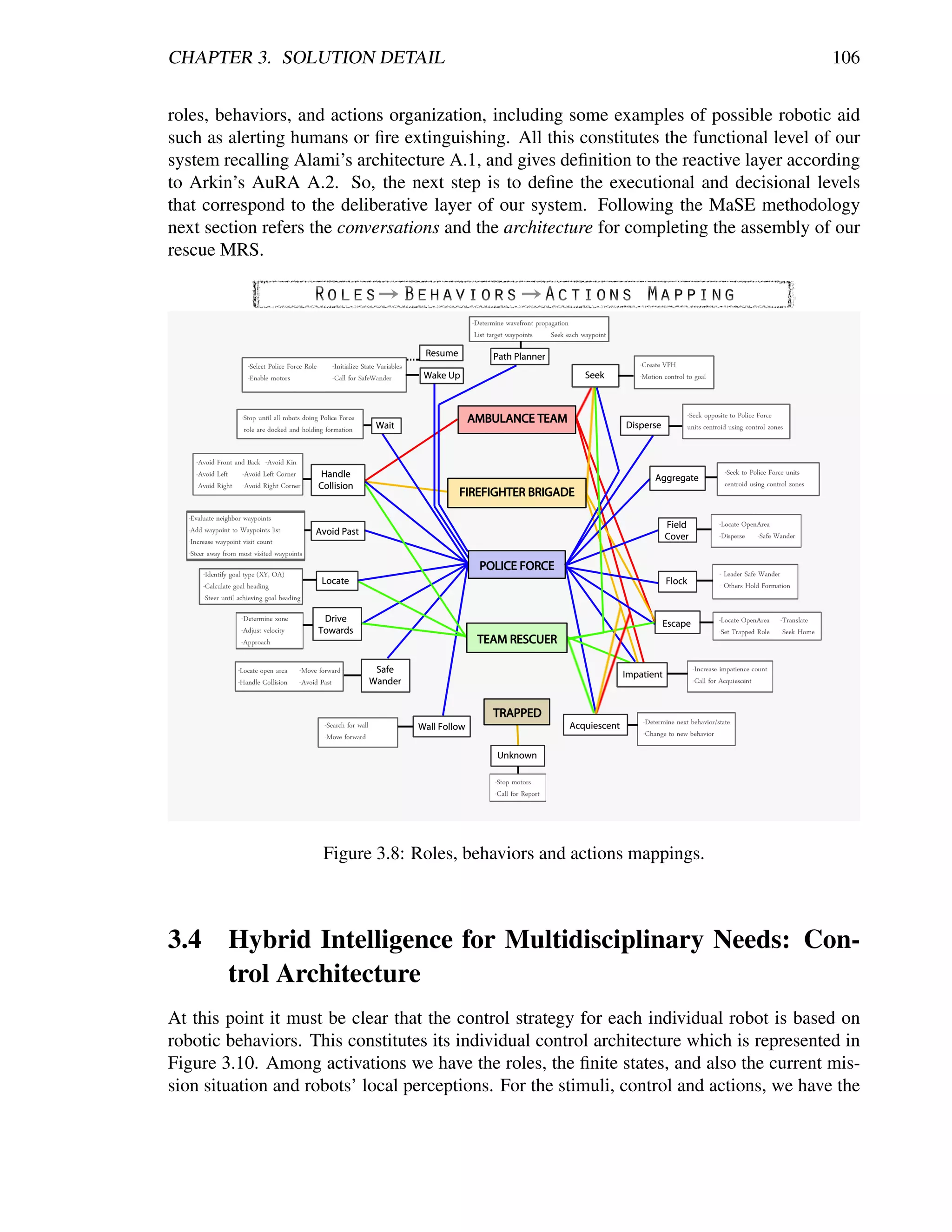

![CHAPTER 3. SOLUTION DETAIL 108
inputs, the ballistic or servo control, and the resultant operations/actions for which the behav-
ior was designed. Also, we have referred that for cases when multiple behaviors are giving a
desired action, a weighted summation is done so as to end up with a fused unique actuator re-
sponse. So, among other already mentioned benefits, this control strategy enable us for close
coupling perceptions and actions so that we can come up with adequate, autonomous and in-
time operations even when dealing with highly unpredictable and unstructured environments.
Nevertheless, there is still the need for a higher level control that ensures the appropriate cog-
nition/planning at the multi-robot level for mission accomplishment. For this reason, a higher
level architecture was created for coupling the rescue team and providing the deliberative and
supervision control layers.
Figure 3.10: Behavior-based control architecture for individual robots. Edited image
from [178].
Providing a deliberative layer to a behavior-based layer, which is nearly reactive, is to
create a hybrid architecture. According to [192], under this hybrid paradigm, the robot first
plans (deliberates) how to best decompose a task into subtasks and then what are the suitable
behaviors to accomplish each subtask. In this work, the robot can choose autonomously the
next best behavior according to its local perceptions, but also its performance can be enhanced
if some global knowledge is provided, meaning that each robot knows something outside of
itself so as to derive a better next best behavior. Using Figure 3.11 it is easier to understand
that a hybrid approach provides our system the possibility to close couple sensing and acting,
but also to enhance the internal operations by some sort of planning. Through this we combine
local control with higher-level control approaches to achieve both robustness and the ability to
influence the entire team’s actions through global goals, plans, or control, in order to end-up
with a much more reliable system [223].
Therefore, using information about the characteristics to make a relevant multi-robot
architecture [218], being inspired in the initiative towards standardization in unmanned sys-
tems composition and communications JAUS [106], and taking into account the most popular
concepts on group architectures [63], we have created a multi-robot architecture with the fol-
lowing design lineaments:
Robotic hardware independent. Leveraging heterogeneity and reusability, hardware
abstraction is essential so the architecture shall not limit to specific robots only.
Mission/domain independent. As a modular and portable architecture, the core should](https://image.slidesharecdn.com/dtc-phd-thesis-finalversion-121215102213-phpapp01/75/PhD-Thesis-Coordination-of-Multiple-Robotic-Agents-for-Disaster-and-Emergency-Response-126-2048.jpg)
![CHAPTER 3. SOLUTION DETAIL 109
Figure 3.11: The Hybrid Paradigm. Image from [192].
remain persistent, while team composition [99] and behavior vary according to different
tasks.
Sliding autonomy. The system can be autonomous or semi-autonomous, the human
operator can control and monitor the robots but is not required for full functionality.
Computer resource independent. Must provide flexibility in computer resources de-
mand, ranging from hi-spec computers to simple handhelds and microcontrollers.
Global centralized, local decentralized. The system can consider global team state
(centralized communication) for increasing performance but should not require it for
local decision-making, thus intelligence resides on robot, refer [153]. Multi-agent sys-
tems that are decentralized include advantages such as fault tolerance, natural exploita-
tion of parallelism, reliability, and scalability. However, achieving global coherency
in these systems can be difficult, thus requiring a central station that enhances global
coordination [223].
Distributed. As shown in [175] distribution fits better for behavior-based control, which
matches our long-term goal and the intended modularity. Also, team composition can be
enhanced distributing by hierarchies (sub-teams) or distributing by peer agents through
a network [63], according to the mission’s needs. With distributed-control it is assumed
that close coupling of perception with action among robots, each working on local goals,
can accomplish a global task.
Upgradeable. Leveraging extendibility and scalability, the architecture must provide
the ease of rapid technology insertion such as new hardware (e.g. sensors) and software
(e.g. behaviors) components. We want a system that has a good balance between gen-
eral enough for extendability, scalability and upgrades, while being specific enough for
concrete contributions.
Interoperability. Three levels of interoperability are desired: human-human, human-
robot and robot-robot.
Reliable communication. Time-suitable and robust communications are essential for
multi-robot coordination. Nevertheless, communications in hazardous environments
should not be essential for task completion, for robustness’ sake. This way the job](https://image.slidesharecdn.com/dtc-phd-thesis-finalversion-121215102213-phpapp01/75/PhD-Thesis-Coordination-of-Multiple-Robotic-Agents-for-Disaster-and-Emergency-Response-127-2048.jpg)
![CHAPTER 3. SOLUTION DETAIL 110
is guaranteed even in the event of a communications breakdown. In this way, our ar-
chitecture should not rely on robots communicating with each other through explicit
communication but rather through the environment and sensing.
One-to-many control. Human operators must be able to command and monitor multi-
ple robots at the same time.
The described architecture is represented in Figure 3.12 (for understanding nomencla-
ture refer to Tables 1.5 and 1.6). For the ease of representing it graphically we have distributed
the levels horizontally being the highest level to the left. At this level the mission is globally
decomposed such as we presented in section 3.1 so that according to a given task, the ex-
ecutional level can derive the most appropriate role and start developing the corresponding
behavioral sequence taking into account their activations including mainly the robot’s local
perceptions. When the corresponding behaviors have been triggered, simultaneous outputs
are fused to derive the optimal command that is sent to the robot actuators or physical re-
sources. This happens for every robot in the team. It is worth to mention that every robot
has a capabilities vector that is intended to match a given task, but since this work is limited
to homogeneous robots, we leave it expressed in the architecture but unused in tests. Finally,
everywhere in the architecture where there are a set of gears represent that a coordination is
being done, either inter-robot (roles and tasks) or intra-robot (behaviors and actions).
Figure 3.12: Group architecture.
Furthermore, for grounding the architecture to hardware resources we decided to use a
topology similar to JAUS [106] because of the clear distinction between levels of competence](https://image.slidesharecdn.com/dtc-phd-thesis-finalversion-121215102213-phpapp01/75/PhD-Thesis-Coordination-of-Multiple-Robotic-Agents-for-Disaster-and-Emergency-Response-128-2048.jpg)
![CHAPTER 3. SOLUTION DETAIL 111
and the simple integration of new components and devices [218]. This topology is shown in
Figure 3.13 and includes the following elements1 :
1. System. At the top, there is the element representing the logical grouping of multiple
robotic subsystems in order to gain some cooperative and cognitive benefits. So, here
is developed the planning, reasoning and decision-making for better team performance
in a given mission. Also, at this element resides the operator control unit OCU (or user
interface UI) that enables human operator to monitor and send higher-level commands
to multiple subsystems, matching our one-to-many control design goal. So, the whole
system can perform in a fully autonomous or semi-autonomous way being operator–
use independent. Finally, this element can also represent signal repeaters for longer
area networks, OCU’s for human-human interoperability, and local centralizations (sub-
teams coordinators) for larger systems.
2. Subsystems. Can be represented by independent entities such as robots and sensor
stations. In general, a subsystem is the entity that is composed of computer nodes and
software/hardware components that enable them to work.
3. Nodes. Contain the assets or components in order to provide a complete application
for ensuring appropriate entity behavior. They can be several types of interconnected
computers enabling for distribution and better team organization, increasing modularity
and simplifying the addition of reusable code as in [77].
4. Components. The place where the services operate. A service could be either hardware
controlling drivers or more sophisticated software algorithms (e.g. a robotic behavior),
and, since it is a class, it can be instantiated in a same node. So, by integrating different
components we give definition to the applications running at nodes. It is worth to say
that the number of components will be mainly limited by the node capabilities.
5. Wireless TCP/IP Communications. Communications between subsystems and the
system element is done through a common Wireless Area Network using the TCP/IP
transport protocol. The messaging between them corresponds to an echoed CCR port
being sent by the Service Forwarder. The Service Forwarder looks for the specified
transport (TCP/IP) and then goes through the network until reaching the subscriber.
This CCR port, is part of the Main Port of standardized services. The message sent
through this port corresponds to a user-defined State class containing the objects that
characterize the subsystem’s status. This class is also part of every service in MSRDS.
So, by implementing this communication structure we enable for an already settled
messaging protocol that can be easily user-modified to achieve specific robotic behavior
and tasks’ requirements within a robust communications network. For details on this
communication process refer to [70].
6. Serial Communications. Inside each subsystem a different communication protocol
can be used among the existing nodes. This communication can be achieved by serial
networks such as RS232 links, CAN buses, or even through Ethernet. It is important
1
Some of the concepts to understand the description of the elements competing service-oriented robotics and
MSRDS were presented in Appendix B and in section 1.4.2 and are detailed in next section.](https://image.slidesharecdn.com/dtc-phd-thesis-finalversion-121215102213-phpapp01/75/PhD-Thesis-Coordination-of-Multiple-Robotic-Agents-for-Disaster-and-Emergency-Response-129-2048.jpg)
![CHAPTER 3. SOLUTION DETAIL 112
to refer that nodes can be microcontrollers, handhelds, laptops, or even workstations;
where at least one of them must be running a windows-based environment for being
able to handle communications within the MSRDS.
Figure 3.13: Architecture topology: at the top the system element communicating wireless
with the subsystems. Subsystems include their nodes, which can be different types of com-
puters. Finally, components represent the running software services depending on the existing
hardware and node’s capabilities.
In Figure 3.13 we show an explicit 2-leveled approach allowing for the hybrid intel-
ligence purpose (or mixed-initiative as in [199]) with main focus in differentiating between
individual robot intelligence (autonomous perception-action) and robotic team intelligence
(human deliberation and planning), matching the decentralization and distribution lineaments.
Moreover, this architecture can be easily extended in accordance to mission requirements and
available software and hardware resources by instantiating the current elements fulfilling our
mission/domain independent and upgradeable design goals. Also, it has the ability to have
more interconnected system elements each with different level of functionality leveraging dis-
tribution, modularity, extendibility and scalability features. It is worth to reinforce that even
if it looks like there is a centralization by using a system element, this is done so as to op-
timize global parameters and to have a monitoring central station rather than for ensuring
functionality.
In summary, the architecture provides the infrastructure for re-coding only what hard-
ware we are going to use and how the mission is going to be solved (tasks). Thus, the system is
settled to couple the team composition, reasoning, decision-making, learning, and messaging
for mission solving [63, 99]. Additionally, in fulfilling such objectives, using the Microsoft
Robotics Developer Studio (MSRDS) robotic framework we match the following design goals
at hand: robot hardware abstraction and rapid technology insertion because of service-oriented
design, and distributed, computer resource independent, time-suitable communications and](https://image.slidesharecdn.com/dtc-phd-thesis-finalversion-121215102213-phpapp01/75/PhD-Thesis-Coordination-of-Multiple-Robotic-Agents-for-Disaster-and-Emergency-Response-130-2048.jpg)
![CHAPTER 3. SOLUTION DETAIL 113
concurrent robotic processing, because of the CCR and DSS characteristics. Also, it provides
us with the infrastructure for reusability within services standardization and an environment
for simple debugging and prototyping among other advantages described in [72]. Next section
provides deeper information on the advantages of developing service-oriented systems plus
the use of MSRDS.
3.5 Service-Oriented Design: Deployment, Extendibility and
Scalability
Concerning the last phase of the MaSE methodology, we finish the design stage with this
section. This constitutes how the MRS is going to be finally designed in order for successful
deployment. Following the state-of-the-art trends in the frameworks for robotic software we
choose to work under the service-oriented robotics (SOR) paradigm. It is important to recall
Appendix B to have a clear definition on services and understanding the relevance of develop-
ing service-oriented solutions over other programming approaches. Also, section 1.4.2 briefly
describes the MSRDS framework and its CCR and DSS components, which are key elements
in this section.
In general, we choose service-oriented because of its manageability of heterogeneity,
the self-discoverable internet capabilities, the information exchange structure, and its high
capabilities for reusability and modularity without depending on fixed platforms, devices,
protocols or technologies. All of these, among other characteristics are present in MSRDS
and ROS.
Nowadays is perhaps more convenient to develop using ROS and not MSRDS, essen-
tially because of the recent growth of service repositories [107]. But at the time most of the
algorithms concerning this dissertation were developed, MSRDS and ROS had a very similar
support among the robotics community. So, choosing among them was a matter of explor-
ing the systems and identifying the one with characteristics that simplified or enhanced our
intended implementations. In this way, the Visual Studio debugging environment, the Con-
currency and Coordination Runtime (CCR), the Decentralized Software Services (DSS), the
integrated simulation service, and the available tutorials at that time turned us towards using
MSRDS as reported in [70].
3.5.1 MSRDS Functionality
The MSRDS is a Windows-based system focused on facilitating the creation of robotics appli-
cations. It is built upon a lightweight service-oriented programming model that makes simple
the development of asynchronous, state-driven applications. Its environment enables users
for interacting and controlling robots with different programming languages. Moreover, its
platform provides a common programming framework that enables code and skills transfer
including the integration of external applications [135]. Its main components are depicted in
Figure 3.14 and described below.
CCR. This is a programming model for multi-threading and inter-task synchronization.
Differently from past programming models, enables the real-time robotics requirements](https://image.slidesharecdn.com/dtc-phd-thesis-finalversion-121215102213-phpapp01/75/PhD-Thesis-Coordination-of-Multiple-Robotic-Agents-for-Disaster-and-Emergency-Response-131-2048.jpg)
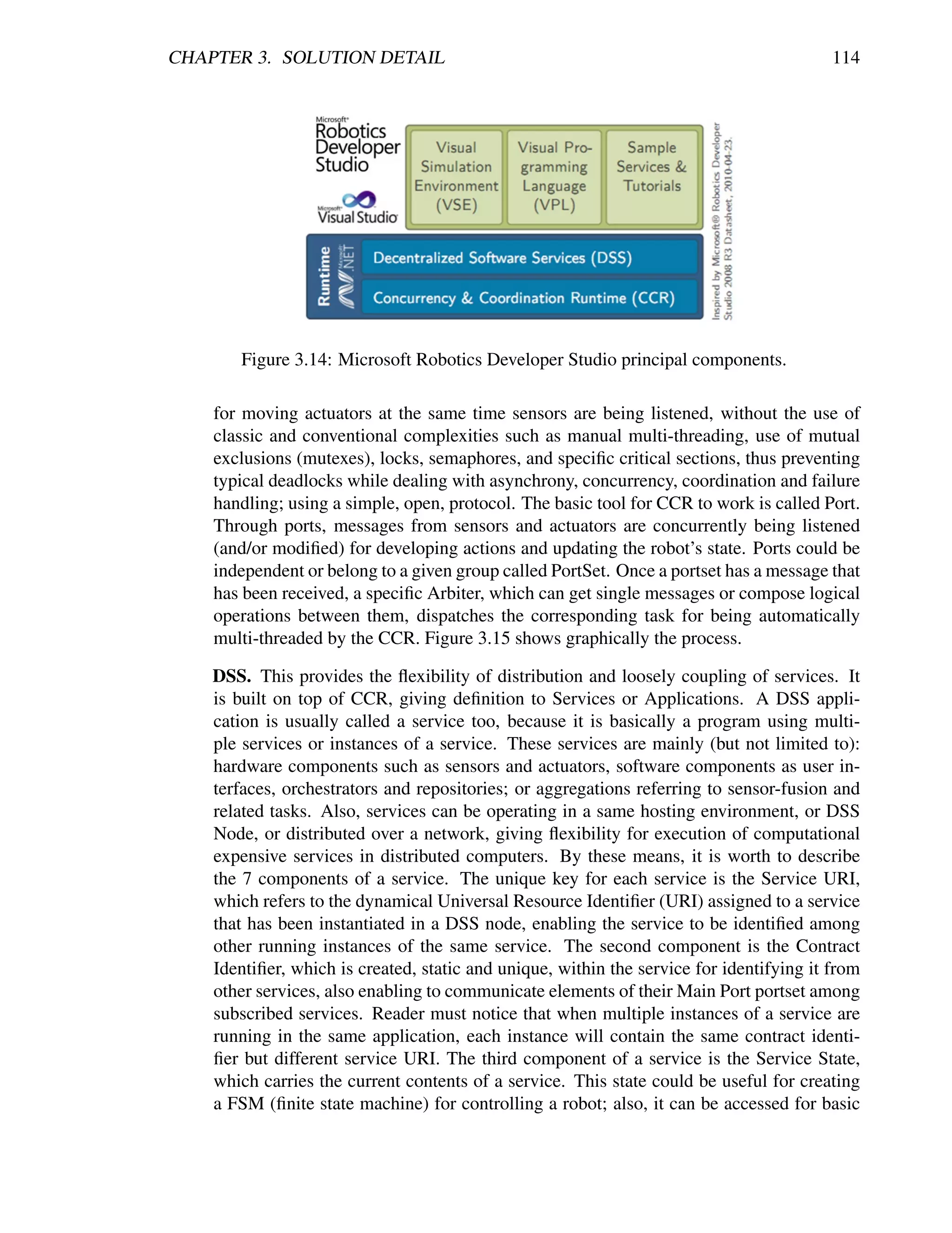
![CHAPTER 3. SOLUTION DETAIL 116
Figure 3.15: CCR Architecture: when a message is posted into a given Port or PortSet, trig-
gered Receivers call for Arbiters subscribed to the messaged port in order for a task to be
queued and dispatched to the threading pool. Ports defined as persistent are concurrently
being listened, while non-persistent are one-time listened. Image from [137].](https://image.slidesharecdn.com/dtc-phd-thesis-finalversion-121215102213-phpapp01/75/PhD-Thesis-Coordination-of-Multiple-Robotic-Agents-for-Disaster-and-Emergency-Response-134-2048.jpg)
![CHAPTER 3. SOLUTION DETAIL 117
Figure 3.16: DSS Architecture. The DSS is responsible for loading services and managing
the communications between applications through the Service Forwarder. Services could be
distributed in a same host and/or through the network. Image from [137].](https://image.slidesharecdn.com/dtc-phd-thesis-finalversion-121215102213-phpapp01/75/PhD-Thesis-Coordination-of-Multiple-Robotic-Agents-for-Disaster-and-Emergency-Response-135-2048.jpg)
![CHAPTER 3. SOLUTION DETAIL 118
Having explained the components, the typical schema for MSRDS to work is shown in
Figure 3.17. This design is used repeatedly in this dissertation. In this way we are flexible to
upgrading sensors or actuators while being able to maintain the core behavioral component (or
user interface) that orchestrates operations from perceptions to actions. At the same time we
are able to plug-in newly developed services or more sophisticated algorithms in repositories
such as in [243, 147, 133, 152, 275, 250, 73, 185], or even taking our encapsulated devel-
opments towards newly proposed architectures for search and rescue such as in [3]. Three
graphic examples of how behaviors are coded under this design paradigm are demonstrated
in Figure 3.18: at the top the handle collision behavior, at the middle the visual recognition
behavior, and at the bottom the seek behavior, all of them with their generic inputs and outputs.
Figure 3.17: MSRDS Operational Schema. Even though DSS is on top of CCR, many services
access CCR directly, which at the same time is working on low level as the mechanism for
orchestration to happen, so it is placed sidewards to the DSS. Image from [137].
Concluding this chapter, we have followed the Multi-agent Systems Engineering method-
ology so as to generate a MRS that is able to deal with urban search and rescue missions. This
included listing the essential requirements and making a hierarchical diagram of the most rel-
evant goals. Then, we decomposed the goals into global and local tasks according to a defined
team of robots. Additionally, we took those tasks into robotic operations and clearly orga-
nized it as roles, behaviors, and actions. Following, we developed an architecture in order to
couple those elements and provide robustness to our system by means of hybrid intelligence,
leaving the deliberative parts to human operators (open for possible future autonomy) and the
autonomous reactions to the robots. Finally, we have explained how everything herein was
coded so that it can be completely reused and upgraded according to state-of-the-art possibil-
ities and needs. Thus, we end-up this chapter with a proposed MRS for rescue missions that
falls into the following classification according to [95, 63, 99, 110]:](https://image.slidesharecdn.com/dtc-phd-thesis-finalversion-121215102213-phpapp01/75/PhD-Thesis-Coordination-of-Multiple-Robotic-Agents-for-Disaster-and-Emergency-Response-136-2048.jpg)
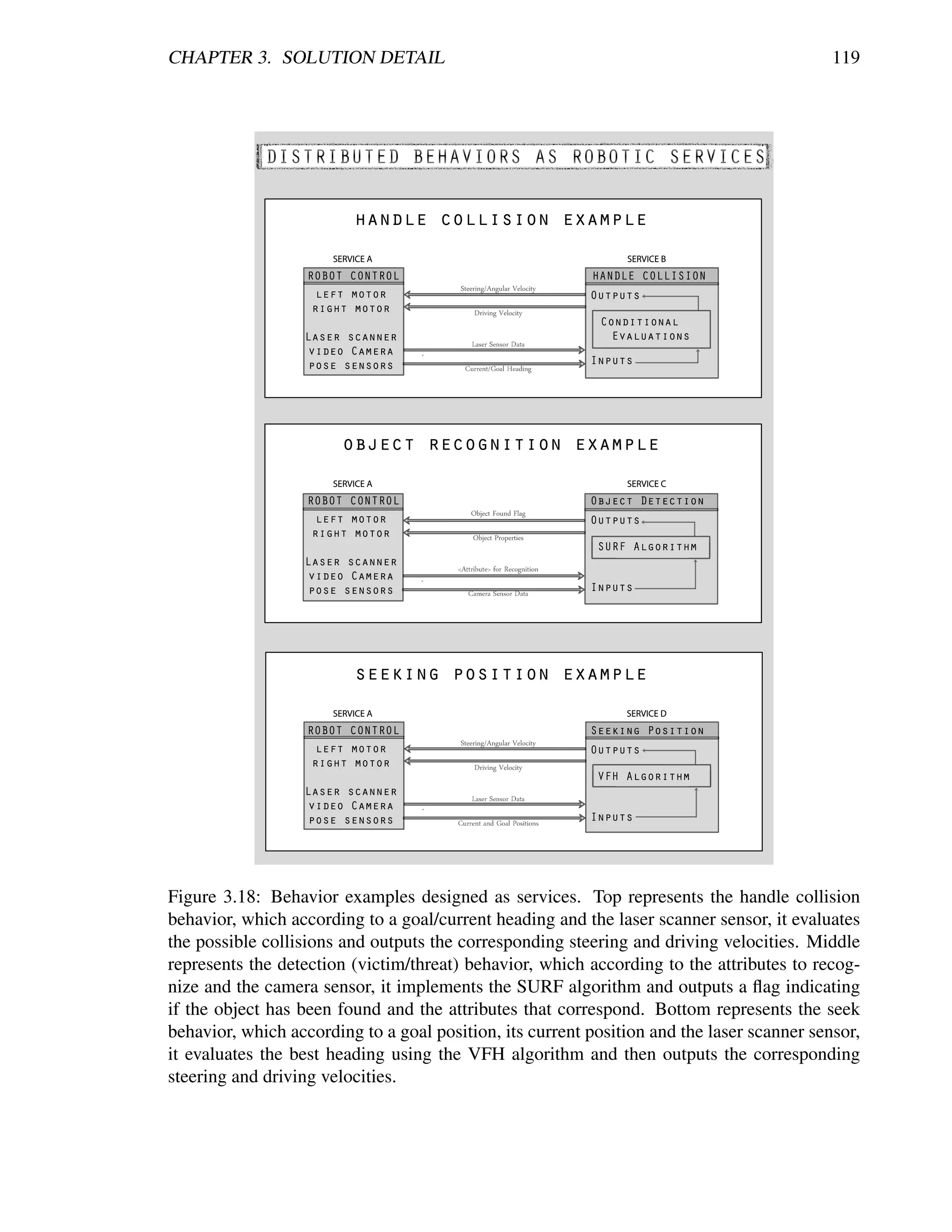
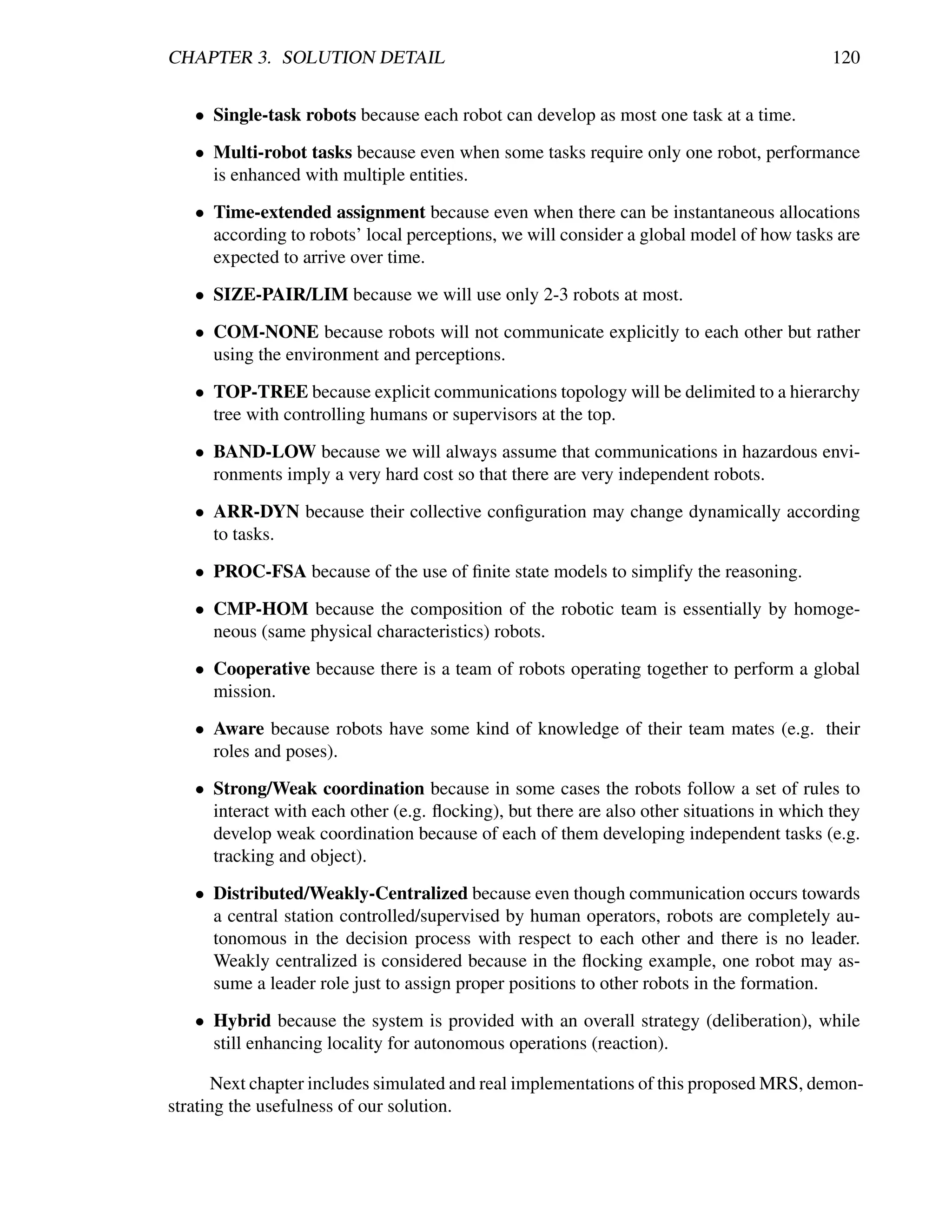
![Chapter 4
Experiments and Results
“The central idea that I’ve been playing with for the last 12-15 years is that
what we are and what biological systems are. It’s not what’s in the head, it’s
in their interaction with the world. You can’t view it as the head, and the
body hanging off the head, being directed by the brain, and the world being
something else out there. It’s a complete system, coupled together.”
– Rodney Brooks. (Robotics Scientist)
C HAPTER O BJECTIVES
— Which simulated and real tests.
— What qualitative and quantitative results.
— How good is it.
It will be to ambitious to think that we can develop tests including all the three global
tasks and every sequence diagram within this dissertation, even semi-autonomously. There
are a lot of open issues outside the scope of this dissertation that make it harder to develop full
operations. Some of them are the simultaneous localization and mapping problem, reliable
communications, sensor data, and actuator operations; robust low-level control for maintain-
ing commanded steering and driving velocities, and even having powerful enough computers
for human–multi-robot interfacing. In this way, we delimited our tests to implement more
relevant behaviors and develop autonomous operations that are easier to be compared with
state-of-the-art literature. This means that for example everything related to the Support and
Relief stage is perhaps to soon to be trying to test [80, 204], but it is still important to include
in our planned solution.
Accordingly, the experimentation phase resided in simulations using the MSRDS VSE
and testing the architecture and the most relevant autonomous operations in real implementa-
tions. The following sections present details on these experiments.
121](https://image.slidesharecdn.com/dtc-phd-thesis-finalversion-121215102213-phpapp01/75/PhD-Thesis-Coordination-of-Multiple-Robotic-Agents-for-Disaster-and-Emergency-Response-139-2048.jpg)
![CHAPTER 4. EXPERIMENTS AND RESULTS 122
4.1 Setting up the path from simulation to real implemen-
tation
This section is included as an argument for the validity of simulated tests over real imple-
mentations. Here we demonstrate a quick way we created to reach reliable 3D simulated
environments and the fast process to go to real hardware within a highly transparent service
interchange.
Using MSRDS, the easiest way we have found for creating simulated environments, be-
sides just modifying already created ones, is to save SimStates (scenes) into .XML files or into
Scripts from SPL (for more information on SPL refer to [125]), and then load them through
C# or VPL. Basically, we developed the entities and environments with SPL. This software
enables the programmer to create realistic worlds, taking simple polygons (for example a
box) with appropriate meshes and making use of a realistic physics engine (the MSRDS uses
AGEIA PhysX Engine). SPL menus enable users for creating the environments and entities
in a script composed by click-based programming. Most typical actuators and sensors are
included in the wide variety of SPL simulation tools. Also, besides the already built robots’
models, SPL provides the easy creation of other robots including joints and drives. Another
way to create these entities is following the samples on C# and importing computer models
for an specific robot or object, or even just importing the already provided models within the
MSRDS installation.
Once the environment and the entities are already defined, the SPL Script is exported
into an XML and then loaded from a C# DSS Service, or the SPL Script is saved and then
loaded from a VPL file, ending-up with the complete 3D simulated world. Figure4.1 shows
graphically these two options. What is more, we have created a service adapting code from
internet repositories that from simple image files we can create 3D maze-like scenarios as
shown in Figure 4.2. This and some other generic services developed within this dissertation
are available online at http://erobots.codeplex.com/.
Figure 4.1: Process to Quick Simulation. Starting from a simple script in SPL we can de-
cide which is more useful for our robotic control needs and programming skills, either going
through C# or VPL.](https://image.slidesharecdn.com/dtc-phd-thesis-finalversion-121215102213-phpapp01/75/PhD-Thesis-Coordination-of-Multiple-Robotic-Agents-for-Disaster-and-Emergency-Response-140-2048.jpg)
![CHAPTER 4. EXPERIMENTS AND RESULTS 123
Figure 4.2: Created service for fast simulations with maze-like scenarios. Available at
http://erobots.codeplex.com/.
Having briefly explained how we set-up simulations, the important thing relies in how
to take it transparently into real implementations. Here, the best aspect is that MSRDS has al-
ready working services for generic differential/skid drives, laser scanners, and webcam-based
sensors. So, for the particular case of the Pioneer robots, MSRDS provides its complete simu-
lated version and drivers for real hardware including every service to control each component
of the robot. In this way, commands sent to the simulated robot are identical than those needed
by the real hardware. Thus, going from simulation to reality when services are properly de-
signed is a matter of changing a reference in the service name which is going to be used in
C#, or changing the corresponding service block in VPL. Figure 4.3 shows the simplicity of
this process.
As may be inferred, one of the biggest issues in robotics research is that simulated hard-
ware never behaves as real hardware. For this reason, next section presents our experiences in
simulating and implementing our behavior services among other technologies.
4.2 Testing behavior services
This section presents the tests we developed in order to explore the functionality of SOR
systems under the implementation of services provided by different enterprises. Also, we de-
veloped experiments concerning the use of different types of technologies in order to observe
the system’s performance. And lastly, we implemented the most relevant behaviors described
in the previous chapter in a service-oriented fashion. All the experiments were developed
both for simulation and real implementation using the Pioneer robots. Additionally, tests
were developed locally using a piggy-backed laptop in real robots or running all the simula-
tion services in the same computer, and remotely by using wireless connected computers; this
is graphically represented in Figure 4.4 and was developed so as to explore the real impact of
the communications overhead among networked services in real-time performance [82, 73].
First, taking advantage from the MSRDS examples, we implemented a simple program](https://image.slidesharecdn.com/dtc-phd-thesis-finalversion-121215102213-phpapp01/75/PhD-Thesis-Coordination-of-Multiple-Robotic-Agents-for-Disaster-and-Emergency-Response-141-2048.jpg)
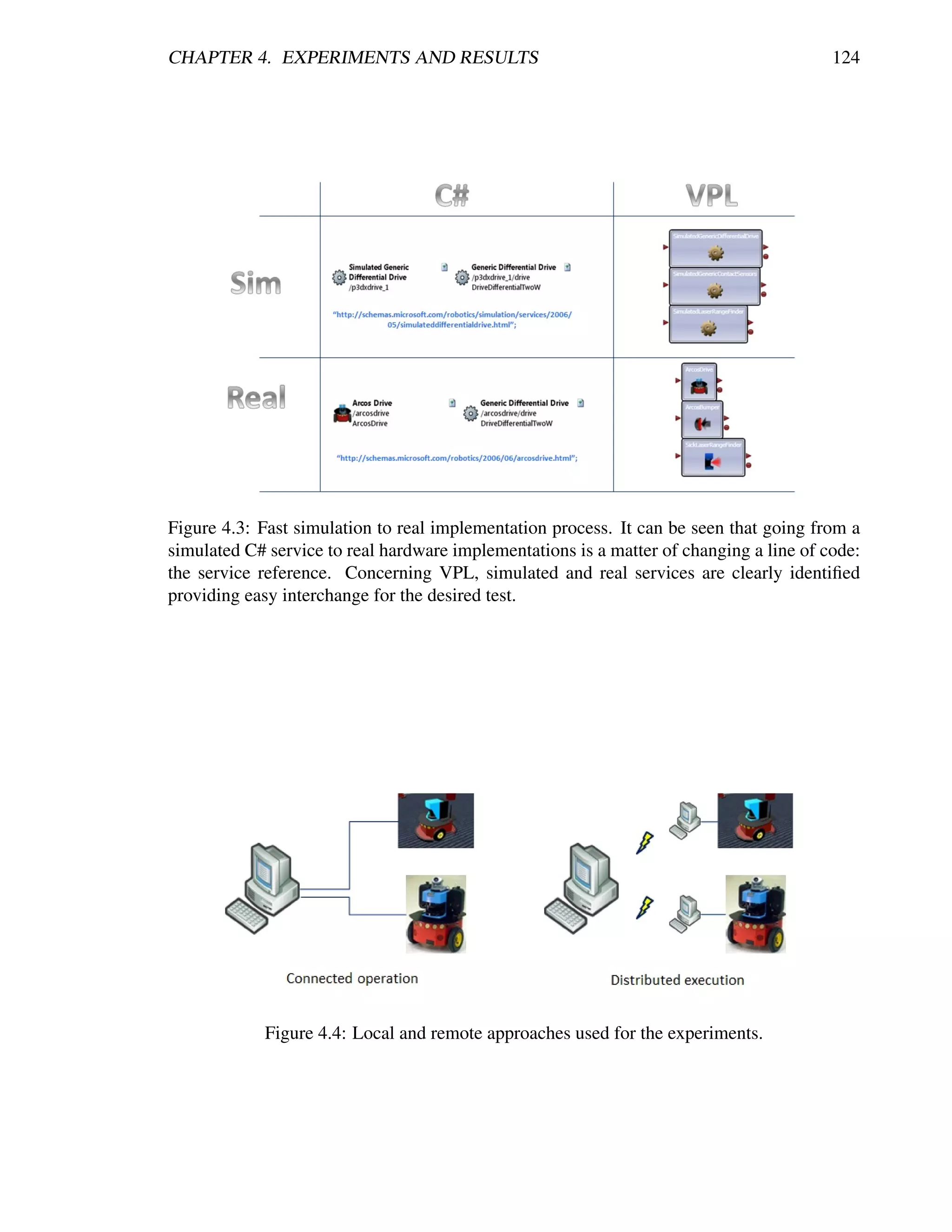
![CHAPTER 4. EXPERIMENTS AND RESULTS 125
for achieving voice-commanded navigation in simulation and real implementations using the
MS Speech Recognition service. This application consisted in recognizing voice-commands
such as ’Turn Left’, ’Turn Right’, ’Move Forwards’, ’Move Backwards’, ’Stop’, and alter-
native phrases for same commands in order control the robot’s movements. This experiment
showed us the feasibility of developing applications using already built services by the same
company providing the development framework. We showed that in either way, VPL or C#,
simulated and real implementation worked equally well. Also, the real-time processing fitted
the needs for controlling a real Pioneer-3AT via serial port without any inconvenient. Addi-
tionally, it must be referred that because of using an already developed service, it was fast
and easy to develop the complete speech recognition application for teleoperated navigation.
Figure 4.5 shows a snapshot of the speech recognition service in its simulated version.
Figure 4.5: Speech recognition service experiment for voice-commanded robot navigation.
Available at http://erobots.codeplex.com/.
Second, considering that using vision sensors requires a high computational processing
time, we decided to test MSRDS under the implementation of an off-the-shelf service pro-
vided by the Company RoboRealm [238]. The main intention was to observe MSRDS real-
time behavior with higher processing demand service, which, at the same time, has been cre-
ated by external-to-Microsoft providers. Therefore, we developed an approach for operating
the RoboRealm vision system through MSRDS. One of the experiments consisted in a visual
joystick, which provided the vision commands for the robot to navigate. It resided in using a
real webcam for tracking an object and determining its center of gravity (COG). So, depend-
ing on the COG location with respect to the center of the image, the speed of the wheels was](https://image.slidesharecdn.com/dtc-phd-thesis-finalversion-121215102213-phpapp01/75/PhD-Thesis-Coordination-of-Multiple-Robotic-Agents-for-Disaster-and-Emergency-Response-143-2048.jpg)
![CHAPTER 4. EXPERIMENTS AND RESULTS 126
settled as if using a typical hardware joystick, thus driving the robot forward, backward, turn-
ing and stopping. Code changes for implementing simulation and real implementation resided
very similar to speech recognition experiment and section 4.1 explanations. Figure 4.6 shows
a snapshot of how simulation looks when running MSRDS and RoboRealm. From this exper-
iment we observed that MSRDS is well-suited for operating with real-time vision processing
and robot control. Results were basically the same for simulation and real implementation
tests. So, this test resulted for us in an application for vision processing and robotics control
using SOA-based robotics, enabling us to implement services as in [275, 116, 279] with a
very simple, fast and yet robust method. Also, it is worth to mention that applications with
RoboRealm are easy to do and very extensive: from simple feature recognition as road signs
for navigation, to more complex situational recognition [207]; in a click-based programming
language.
Figure 4.6: Vision-based recognition service experiment for visual-joystick robot navigation.
Available at http://erobots.codeplex.com/.
Finally, even though for every real implementation we used the Pioneer services pro-
vided within MSRDS for controlling its motors, in this experiment we implemented au-
tonomous mobile robot navigation with Laser Range Finder sensor service and MobileR-
obots Arcos Bumper service, as the external-to-Microsoft providers of hardware-controlling
services. Keeping our exploration purposes on SOA-based robotics, we created a boundary-
follow behavior for testing the simulated result and the real version of it, as well as capabilities
for real-time orchestration between sensor and actuator services. Here, an interesting behavior
was observed: while in simulation the robot followed the wall without any trouble, in real ex-
periments the robot sometimes starts turning trying to find the lost wall. The obvious answer
is that real sensors are not as predictable and robust as in simulation. Thus we reinforced the
point of advantage with SOA-based robotics for fast achieving real experiments in order to
deal with real and more relevant robotics’ problems. With this experiment the most interesting
observations reside in the establishment of MSRDS as an orchestration service for interacting
with real sensor and actuator services provided by MobileRobots, the Pioneer manufacturer.
Also, that we observed appropriate real-time behavior with capabilities of instant reaction to
minimal sensor changes and no communication problem neither locally nor remote.
Therefore, having obtained confidence in the SOR approach we started developing the
behaviors described in the previous chapter in a service-oriented fashion, intending to reduce](https://image.slidesharecdn.com/dtc-phd-thesis-finalversion-121215102213-phpapp01/75/PhD-Thesis-Coordination-of-Multiple-Robotic-Agents-for-Disaster-and-Emergency-Response-144-2048.jpg)
![CHAPTER 4. EXPERIMENTS AND RESULTS 127
time costs in the development and deployment. Among the most relevant include: wall-follow,
seek (used by 15 out of the 36 behaviors), flock (including safe wander, hold formation, lost,
aggregate and every formation used), field cover1 (including disperse, safe wander, handle
collisions, avoid past and move forward), and victim/threat (visual recognition). Figures 4.7-
4.11 show snapshots of these robotic behavior services, all of which are also available at
http://erobots.codeplex.com/. Other behaviors not shown or not implemented include more
sophisticated operations such as giving aid, which is a barely explored set of actions accord-
ing to state-of-the-art literature and out of the scope of this dissertation; or perhaps have no
significant appreciation such as wait or resume.
Figure 4.7: Wall-follow behavior service. View is from top, the red path is made of a robot
following the left (white) wall in the maze, while the blue one corresponds to another robot
following the right wall.
Figure 4.8: Seek behavior service. Three robots in a maze viewed from the top, one static and
the other two going to specified goal positions. The red and blue paths are generated by each
one of the navigating robots. To the left of the picture a simple console for appreciating the
VFH [41] algorithm operations.
1
Refer to Appendix D for complete detail on this behavior.](https://image.slidesharecdn.com/dtc-phd-thesis-finalversion-121215102213-phpapp01/75/PhD-Thesis-Coordination-of-Multiple-Robotic-Agents-for-Disaster-and-Emergency-Response-145-2048.jpg)
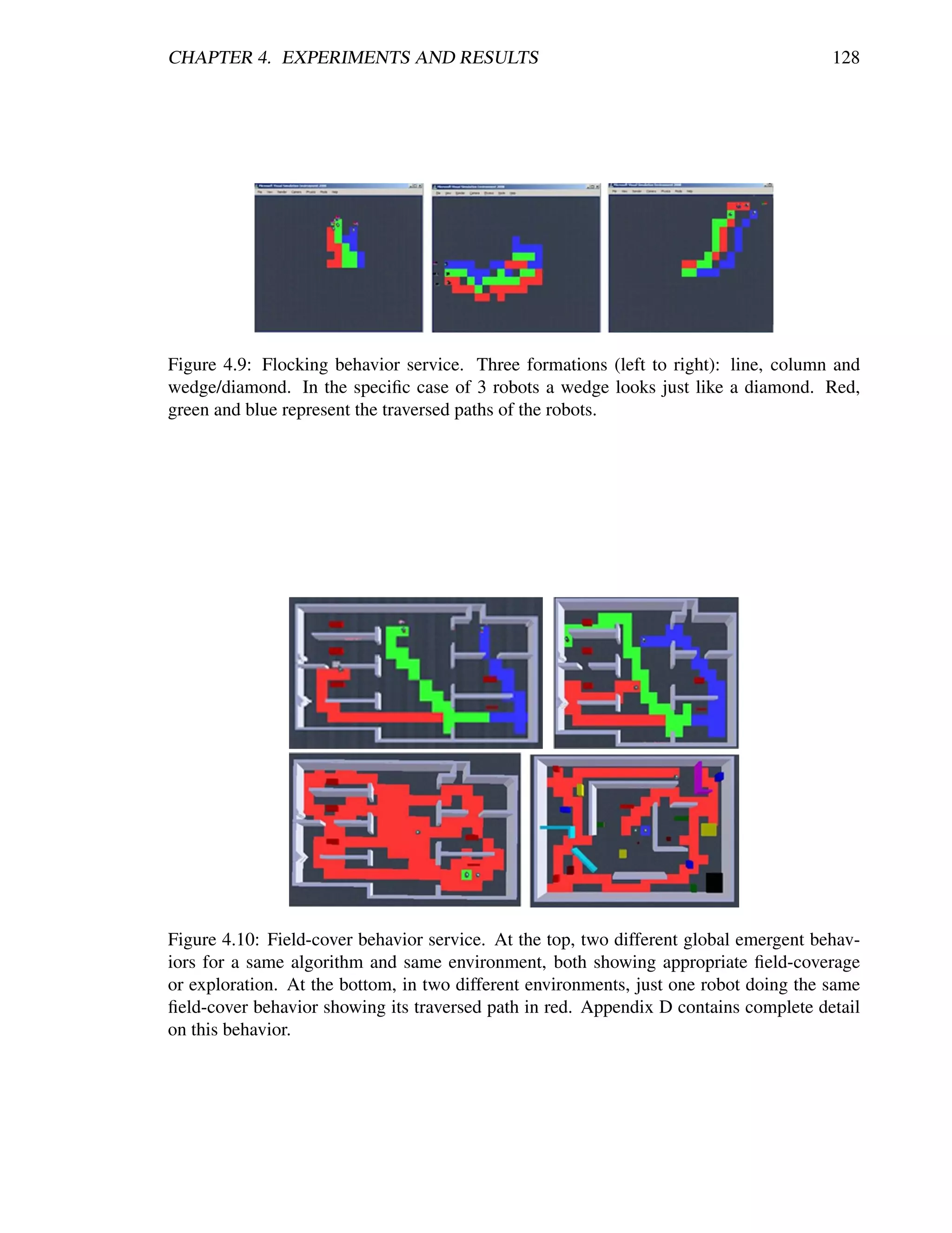
![CHAPTER 4. EXPERIMENTS AND RESULTS 129
Figure 4.11: Victim and Threat behavior services. Being limited to vision-based detec-
tion, different figures were used to simulate threats and victims according to recent litera-
ture [116, 20, 275, 207]. To recognize them, already coded algorithms were implemented
including SURF [26], HoG [90] and face-detection [279] from the popular OpenCV [45] and
EmguCV [96] libraries.](https://image.slidesharecdn.com/dtc-phd-thesis-finalversion-121215102213-phpapp01/75/PhD-Thesis-Coordination-of-Multiple-Robotic-Agents-for-Disaster-and-Emergency-Response-147-2048.jpg)
![CHAPTER 4. EXPERIMENTS AND RESULTS 130
Closing the section, the best experience from these tests resided in achieving fast 3D
simulation environments and then quickly getting into the real implementations using off-the-
shelf services with MSRDS. Also, since we observed appropriate processing times under real
robotic requirements, it gave us the confidence towards implementing our intended architec-
ture without hesitating about any possible communication inconvenient. Next section details
the experiences with the implementation of our proposed infrastructure.
4.3 Testing the service-oriented infrastructure
At this point, experiments lead us into a nice integrated application containing all the available
behavior services that have been coded, plus additional features such as being able to create 3D
simulation environments as fast as creating an image file, and even almost perfect localization
and mapping as can be appreciated in Figure 4.12. Nevertheless, in the words of Mong-ying
A. Hsieh et al. in [131]: “Field-testing is expensive, tiring, and frustrating, but irreplaceable in
moving the competency of the system forward. In the field, sensors and perceptual algorithms
are pushed to their limits [. . . ]”. Thus, achieving good localization is perhaps the biggest
problem towards successfully implementing every coded behavior in real robots. So, in this
section we describe the first step towards relevant real implementations: test the infrastructure.
Figure 4.12: Simultaneous localization and mapping features for the MSRDS VSE. Robot 1
is the red path, robot 3 the green and robot 3 the blue. They are not only mapping the environ-
ment by themselves, but also contributing towards a team map. Nevertheless localization is a
simulation cheat and laser scanners have no uncertainty as they will have in real hardware.
It is worth to recall that many architectures for MRS had been proposed [63, 223] and
evaluated [218], but there are only a few working under the service-oriented paradigm and
fulfilling the architectural and coordination requirements we address. One example can be
SIRENA [38], a JAVA-based framework to seamlessly connect heterogeneous devices from
the industrial, automotive, telecommunication and home automation domains. Maybe it is
one of the first projects that pointed out the benefits of using a Service-Oriented Architecture
(SOA). Even though in its current state of development it has showed its feasibility and func-
tionality, communication has been limiting scalability in the intended application for real-time](https://image.slidesharecdn.com/dtc-phd-thesis-finalversion-121215102213-phpapp01/75/PhD-Thesis-Coordination-of-Multiple-Robotic-Agents-for-Disaster-and-Emergency-Response-148-2048.jpg)
![CHAPTER 4. EXPERIMENTS AND RESULTS 131
embedded networked devices. A second example is SENORA [231], this framework, based
on peer to peer technology, can accommodate a large number of mobile robots with limited
affects on the quality of service. It has been tested on robots working cooperatively to obtain
sensory information from remote locations. Its efficiency and scalability have been demon-
strated. Nevertheless, there has been a lack of adequate abstraction and standardization caus-
ing difficulties in reusing and in the integration of services. As a third example there is [73],
which consists in an instrumented industrial robot that must be able to localize itself, map
its surroundings and navigate autonomously. The relevance of this project is that everything
works as a service-on-demand, meaning that there were localization services, navigation ser-
vices, kinematic control services, feature extraction services, SLAM services, and some other
operational services. These allows for upgrading any of the services without demanding any
changes in other parts of the system. Accordingly, in our work we want to demonstrate ade-
quate abstractions as in [73] but already working with multiple robots as [231] intended, while
maintaining time-suitable communications for achieving good multi-robot interoperability.
Additionally, we want to fulfill architectural requirements such as robot hardware ab-
straction, extendibility and scalability, reusability, simple upgrading and integration of new
components and devices, simple debugging, ease of prototyping, and use of standardized tools
to add relevance. Also, we concern on particular requirements for multi-robot coordination
such as having a persistent structure allowing for variations at team composition, an approach
to hybrid intelligence control for decentralization and distribution, and the use of suitable mes-
saging allowing the user to easily modify what needs to be communicated. In this way, the
experiments are intended to demonstrate functionality and interoperability with a team of Pio-
neer robots achieving: time-suitable communications, individual and cooperative autonomous
operations, semi-autonomous user-commanded operations, and the ease of adding/removing
robotic units to the working system. Our focus is to prove that the infrastructure facilitates the
integration of current and new developments in terms of robotic software and hardware, while
keeping a modular structure in order for it to be flexible without demanding complete system
modifications.
In this way, we implemented the architecture design and topology described in sec-
tion 3.4. For the system element we used a laptop running Windows 7 with Intel Core 2 Duo at
2.20 GHz and 3 GB RAM. For subsystems (homogeneous) we used 3 RS232-connected nodes
consisting in: 1) a laptop running Windows XP with Intel Atom at 1.6GHz and 1 GB RAM
for organizing data and controlling the robot including image processing and communications
with system element; 2) the Pioneer Microcontroller with the embedded ARCOS software for
managing the skid-drive, encoders, compass, bumpers, and sonars ; and 3) a SICK LMS200
sensor providing laser scanner readings. System and subsystems were connected through the
WAN at our laboratory, which was being normally used by other colleagues. Now, the typical
configuration when running this kind of infrastructures requires for a human operator to log
into an operator control unit (OCU), then connect to robots, communicate high-level data, and
finally robotic platforms receive the message and start operating. In our architecture steps are
similar:
1. Every node in the subsystem must be started, and then services will load and start the
specified partners for operating and subscribing all components.
2. Run the system service specifying subscriptions to the existing subsystems. In this](https://image.slidesharecdn.com/dtc-phd-thesis-finalversion-121215102213-phpapp01/75/PhD-Thesis-Coordination-of-Multiple-Robotic-Agents-for-Disaster-and-Emergency-Response-149-2048.jpg)
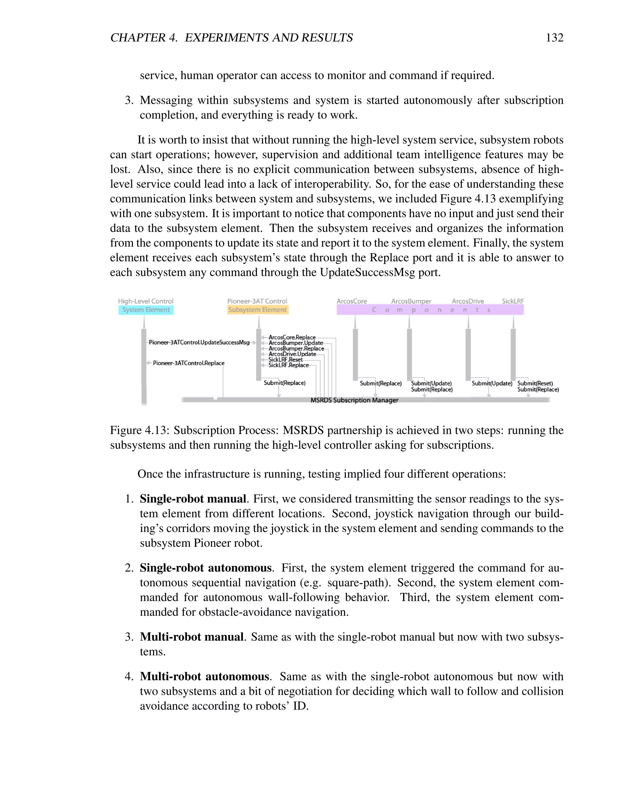
![CHAPTER 4. EXPERIMENTS AND RESULTS 133
Table 4.1: Experiments’ results: average delays
Single-Robot (15 Minutes) Multi-Robot (30 Minutes)
Messages Sent from Subsystem: 4213 Messages Sent from Subsystem 1: 8778
Messages Received in System: 4210 Messages Received in System: 8762
Total loss: 0.07% Total loss: 0.18%
Messages per second: 4.6778 Messages per second: 4.6890
Highest delay: 0.219 s Highest delay: 0.234 s
Messages Sent from Subsystem 2: 8789
Messages Received in System: 8764
Total loss: 0.28%
Messages per second: 4.6954
Highest delay: 0.219 s
In spite of the four basic differences in our experiments and that the number of col-
leagues using the network as well as the subsystems’ positions were changing, results in
delays showed practically the same. Some of these results are shown in Table 4.1.
These experiments showed the successful instantiation of the architecture using mul-
tiple Pioneer robots and a remote station. Quantitative preliminary results indicated that
the architecture is task-independent and robot-number-independent when referring to time-
suitable communications including a well balanced messaging (less than 0.1% difference for
2 homogeneous robots). Also, it enabled us for fully controlling the robots and reaching the
requirements for concurrent robotic processing, while having an appropriate communication
time with the higher level control during the manual and autonomous operations. Finally, it
is worth to emphasize that even when non-SOA approaches could reduce delays to half as
demonstrated in [4], the observed results suffice for good MRS interoperability and thus the
real impact could not be considered as a disadvantage.
In view of that, for our intended application in search and rescue missions, where robots
need to exchange application-specific data or information, such as capabilities, tasks, loca-
tion, sensor readings, etc.; this architecture comes to be useful. Also, even though run-time
overhead is not as important as it was because modern hardware is fast and cheap, CCR and
DSS come to be essential for reducing complexity. Therefore, in next section we detail more
sophisticated operations using this infrastructure but with a different set of robots.
4.4 Testing more complete operations
Because of the huge amount of operations conforming each of the described global tasks in a
rescue mission and the lack of a good possibility to evaluate our contributions with literature,
we decided to implement the most popular operations for a rescue MRS: the autonomous ex-
ploration of unknown environments. This operation has become very popular for the robotics
community mainly because it is a challenging task, with several potential applications. The](https://image.slidesharecdn.com/dtc-phd-thesis-finalversion-121215102213-phpapp01/75/PhD-Thesis-Coordination-of-Multiple-Robotic-Agents-for-Disaster-and-Emergency-Response-151-2048.jpg)
![CHAPTER 4. EXPERIMENTS AND RESULTS 134
main goal in robotic exploration is to minimize the overall time for covering an unknown envi-
ronment. So, we used our field-cover behavior to achieve single and multi-robot autonomous
exploration, evaluating essentially the time for covering a complete environment. For a com-
plete description on how the algorithm works refer to Appendix D and reference [71]. Fol-
lowing are presented the simulated and real tests.
4.4.1 Simulation tests
For simulation test, we used a set of 3 Pioneer robots in their simulated version for MSRDS.
Also, for better appreciation of our results, we implemented a 200 sq. mt 3D simulated
environment qualitatively equivalent to the used in Burgard’s work [58], one of the most
relevant in recent literature. Robots are equipped with laser range scanners limited to 2m and
180◦ view, and have a maximum velocity of 0.5m/s. As for metrics, we used the percentage
of explored area over time as well as a exploration quality metric proposed to measure the
balance of individual exploration within multiple robots [295], refer to Table 4.2.
METRIC DESCRIPTION EXAMPLE
EXPLORATION For single and multiple robots, mea- In Figure 4.25, an av-
(%) sures the percent of gathered locations erage of 100% Explo-
from the total 1-meter grid discrete en- ration was achieved in
vironment. With this metric we know 36 seconds.
the total explored area in a given time
and the speed of exploration.
EXPLORATION For multiple robots only, measures In Figure 4.27(b), two
QUALITY (%) how much of the total team’s explo- robots reached 100%
ration has been contributed by each Exploration with ap-
teammate. With this metric we know proximately 50% Ex-
our performance in terms of resource ploration Quality each.
management and robot utilization.
Table 4.2: Metrics used in the experiments.
Single Robot Exploration
Since our algorithm can do a dispersion or not, depending on the robots’ proximity, we de-
cided to test it for an individual robots first. These tests first considered the Safe Wander
behavior without the Avoid Past action, so as to evaluate the importance of the wandering
factor [10]. Figure 4.14 shows representative results for multiple runs using different wander
rates. Since we are plotting the percentage of exploration over time, the flat zones in the curves
indicate exploration redundancy (i.e. there was a period of time in which the robot did not
reach unexplored areas). Consequently, in these results, we want to minimize the flat zones
in the graph so as to refer to a minimum exploration redundancy, while gathering the highest
percentage in the shortest time. It is worth to mention that by safe wandering we can’t ensure
total exploration so we defined a fixed 3-minute period to compare achieved explorations. We
observed higher redundancy for 15% and 5% wandering rates as presented in Figures 4.14(a)](https://image.slidesharecdn.com/dtc-phd-thesis-finalversion-121215102213-phpapp01/75/PhD-Thesis-Coordination-of-Multiple-Robotic-Agents-for-Disaster-and-Emergency-Response-152-2048.jpg)
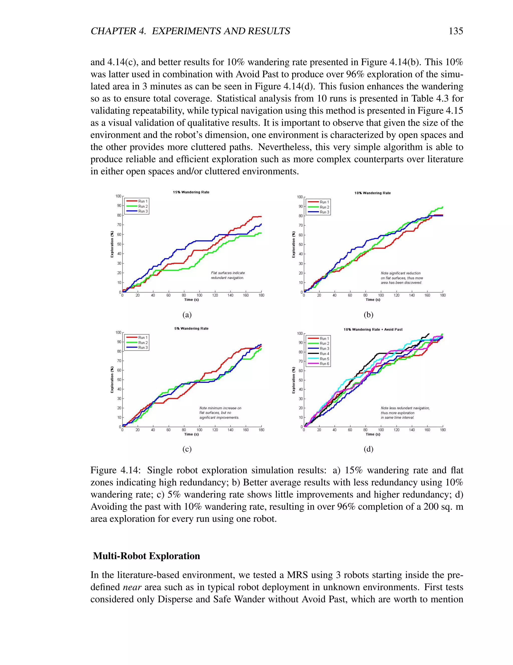
![CHAPTER 4. EXPERIMENTS AND RESULTS 136
RUNS AVERAGE STD. DEVIATION
10 177.33 s 6.8 s
Table 4.3: Average and Standard Deviation for full exploration time in 10 runs using Avoid
Past + 10% wandering rate with 1 robot.
(a) (b)
Figure 4.15: Typical navigation for qualitative appreciation: a) The environment based upon
Burgard’s work in [58]; b) A second more cluttered environment. Snapshots are taken from
the top view and the traversed paths are drawn in red. For both scenarios the robot efficiently
traverses the complete area using the same algorithm. Black circle with D indicates deploy-
ment point.
because results show sometimes quite efficient exploration, while other times can’t ensure full
exploration. So, this combination may be appropriate in cases where it is preferable to get an
initial rough model of the environment and then focus on improving potentially interesting
areas with more specific detail (e.g. planetary exploration) [295].
Nevertheless, more efficient results for cases where guaranteed total coverage is neces-
sary (e.g. surveillance and reconnaissance, land mine detection [204]) were achieved using
our exploration algorithm using Avoid Past. In our first approach, we intended to be less-
dependent on communications so that robots avoid their own past only. Figure 4.16 shows
the typical results for a single run with the total exploration on Figure 4.16(a) and exploration
quality on Figure 4.16(b). We seek for the least flat zones in robots’ exploration as well as
a reduced team redundancy, which represented locations visited by two or more robots. We
can see that for every experiment, full exploration is achieved averaging a time reduction to
about 40% of the required time for single robot exploration in the same environment, and
even to about 30% without counting the dispersion time. This is highly coherent to what is
appreciated in the exploration quality, which showed a trend towards a perfect balance just
after dispersion occurred, meaning that with 3 robots we can almost explore 3 times faster.
Additionally, team redundancy holds around 10%, representing a good resource management.
It must be clear that, because of the wandering factor, not every run gives the same results,
but even when atypical cases occurred, such as when one robot is trapped at dispersion, the
team delays exploration while being redundant in their attempt to disperse, and then develops
a very efficient full exploration in about 50 seconds after dispersion, while resulting in a per-
fectly balanced exploration quality. Table 4.4 presents the statistical analysis from 10 runs so](https://image.slidesharecdn.com/dtc-phd-thesis-finalversion-121215102213-phpapp01/75/PhD-Thesis-Coordination-of-Multiple-Robotic-Agents-for-Disaster-and-Emergency-Response-154-2048.jpg)
![CHAPTER 4. EXPERIMENTS AND RESULTS 137
as to validate repeatability.
(a) Exploration. (b) Exploration Quality.
Figure 4.16: Autonomous exploration showing representative results in a single run for 3
robots avoiding their own past. Full exploration is completed at almost 3 times faster than
using a single robot, and the exploration quality shows a balanced result meaning an efficient
resources (robots) management.
RUNS AVERAGE STD. DEVIATION
10 74.88 s 5.3 s
Table 4.4: Average and Standard Deviation for full exploration time in 10 runs using Avoid
Past + 10% wandering rate with 3 robots.
The next approach consider avoiding also teammates’ past. For this case, we assumed
that every robot can communicate its past locations concurrently during exploration, which
we know can be a difficult assumption in real implementations. Even though we were expect-
ing a natural reduction in team redundancy, we observed a higher impact of interference and
no improvements in redundancy. These virtual paths to be avoided tend to trap the robots,
generating higher individuals’ redundancy (flat zones) and thus producing an imbalanced ex-
ploration quality, which resulted in larger times for full exploration in typical cases, refer to
Figures 4.17(a) and 4.17(b). In these experiments, atypical cases such as where robots got dis-
persed the best they can, resulted in exploration where individuals have practically just their
own past to avoid and thus giving similar results to avoiding their own past only. Table 4.5
presents the statistical analysis from 10 runs running this algorithm. Finally, Figure 4.18
shows a visual qualitative comparison between Burgard’s results and our results. It can be
observed a high similarity with way different algorithms.
An additional observation to exploration results is shown in Figure 4.19, a naviga-
tional emergent behavior that results from running the exploration algorithm for a long time,
which can be described as territorial exploration or even as in-zone coverage for surveillance
tasks [204, 92]. What is more, in Figure 4.20 we present the navigation paths of the same
autonomous exploration algorithm in different environments including open areas, cluttered
areas, dead-end corridors and rooms with minimum exits; all of them with inherent charac-
teristics for challenging multiple robots efficient exploration. It can be observed that even in](https://image.slidesharecdn.com/dtc-phd-thesis-finalversion-121215102213-phpapp01/75/PhD-Thesis-Coordination-of-Multiple-Robotic-Agents-for-Disaster-and-Emergency-Response-155-2048.jpg)
![CHAPTER 4. EXPERIMENTS AND RESULTS 138
(a) Exploration. (b) Exploration Quality.
Figure 4.17: Autonomous exploration showing representative results in a single run for 3
robots avoiding their own and teammates’ past. Results show more interference and imbalance
at exploration quality when compared to avoiding their own past only.
RUNS AVERAGE STD. DEVIATION
10 92.71 s 4.06 s
Table 4.5: Average and Standard Deviation for full exploration time in 10 runs using Avoid
Kins Past + 10% wandering rate with 3 robots.
(a) (b)
Figure 4.18: Qualitative appreciation: a) Navigation results from Burgard’s work [58]; b) Our
gathered results. Path is drawn in red, green and blue for each robot. High similarity with a
much simpler algorithm can be appreciated. Black circle with D indicates deployment point.](https://image.slidesharecdn.com/dtc-phd-thesis-finalversion-121215102213-phpapp01/75/PhD-Thesis-Coordination-of-Multiple-Robotic-Agents-for-Disaster-and-Emergency-Response-156-2048.jpg)
![CHAPTER 4. EXPERIMENTS AND RESULTS 139
adverse scenarios appropriate autonomous exploration is always achieved. Particularly, we
observed that when dealing with large open areas such as in Figure 4.20(a) robots fulfill a
quick overall exploration of the whole environment, but we noticed that it takes more time
to achieve an in-zone coverage compared with other scenarios. We found that this could be
enhanced by avoiding also kins’ past, but it will imply full dependence on communications,
which are highly compromised in large areas. Another example is shown in Figure 4.20(b)
considering cluttered environments, these situations demand for more coordination at the
dispersion process as well as difficulties for exploring close gaps. Still, it can be observed
that robots were successfully distributed and practically achieved full exploration. Next, Fig-
ure 4.20(c) presents an environment that is particularly characterised because of compromis-
ing typical potential fields solutions because of reaching local minima or even being trapped
within avoiding the past and a dead-end corridor. With this experiment we observed that it
took more time for the robots to get dispersed and to escape the dead-end corridors in order to
explore the rooms, nevertheless full exploration is not compromised and robots successfully
navigate autonomously through the complete environment. The final environment shown in
Figure 4.20(d) presents an scenario where the robots are constantly getting inside rooms with
minimum exits, thus complicating the efficient dispersion and spreading through the environ-
ment. In spite of that, it can be appreciated how the robots efficiently explore the complete
environment. We observed that the most relevant action for successfully exploring this kind
of environments is the dispersion that robots keep on doing each time 2 or more face each
other.
Figure 4.19: The emergent in-zone coverage behavior for long time running the exploration
algorithm. Each color (red, green and blue) shows an area explored by a different robot. Black
circle with D indicates deployment point.
Summarizing, we have successfully demonstrated that our algorithm works for single
and multi-robot autonomous exploration. What is more, we have demonstrated that even
when it is way simpler, it achieves similar results to complex solutions over literature. Finally,
we have tested its robustness against different scenarios and still get successful results. So,
the next step is to demonstrate how it works with real robots.
4.4.2 Real implementation tests
For the field tests another set of robots was used. It consisted in a pair of Jaguar V2 robots with
the characteristics presented below. Further information can be found at DrRobot Inc. [134].
Power. Rechargeable LiPo battery at 22.2V 10AH.](https://image.slidesharecdn.com/dtc-phd-thesis-finalversion-121215102213-phpapp01/75/PhD-Thesis-Coordination-of-Multiple-Robotic-Agents-for-Disaster-and-Emergency-Response-157-2048.jpg)
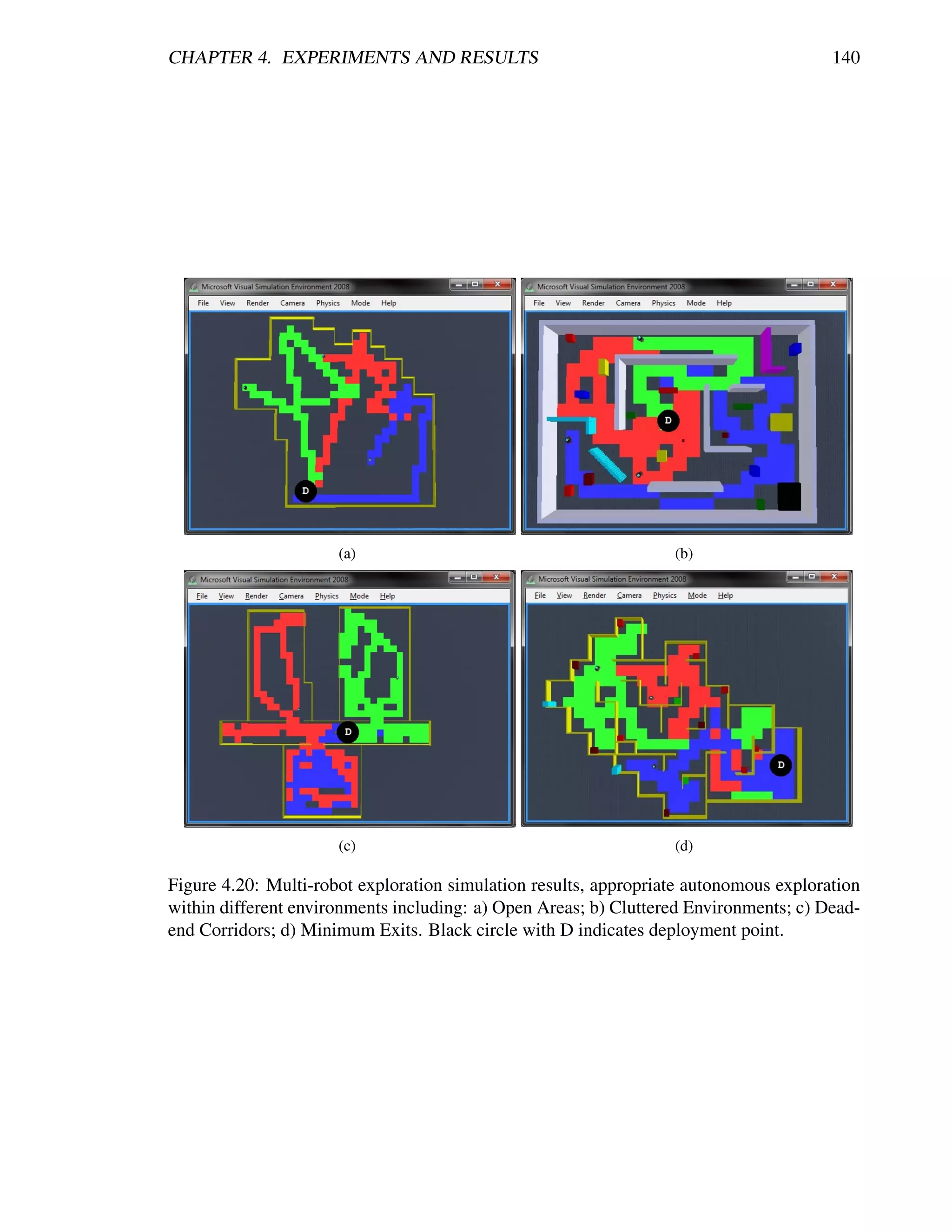
![CHAPTER 4. EXPERIMENTS AND RESULTS 141
Mobility. Skid-steering differential drive with 2 motors for tracks and 1 for the arms,
all of them at 24V and rated current 2.75A. This turns into a carrying capacity of 15Kg
and 50Kg dragging.
Instrumentation. Motion and sensing controller (PWM, position and speed control),
5Hz GPS and 9 DOF IMU (Gyro/Accelerometer/Compass), laser scanner (30m), tem-
perature sensing and voltage monitoring, headlights and color camera (640x480, 30fps)
with audio.
Dimensions. Height: 176mm. Width: 700mm. Length: 820mm (extended arms) /
640mm (folded arms) Weight: 25Kg.
Communications. WiFi802.11G and Ethernet.
For controlling the robots as well as for appropriately interfacing with a system ele-
ment two OCUs (or UIs) were created. Concerning the interface for robot control, meaning
the subsystems control application, where the behaviors are processed along with the local
perceptions, Figure 4.21 shows how it is composed. The robot connection section is for spec-
ifying to which robot the interface is going to be connected. The override controls are for
manually moving the robot when the computer is wireless linked to the robot. The mapping
section uses a counting strategy for colouring an image file in grayscale according to laser
scanner readings and current pose at every received update (approximately at 10Hz). The
positioning sensors section include the gyroscope, accelerometer, compass, encoders, and gps
readings, plus a section referring the pose estimation of the robot. When operations are out-
doors and the gps is working properly the satellital view section displays the current latitude
and longitude readings as well as the orientation of the robot. Finally, the camera and laser
display section include the video streaming and the laser readings in two different views: top
and front.
Concerning the interface for the system element, where the next state is commanded
and robots are monitored and possibly overridden by human operator, Figure 4.22 shows how
it is composed. The first thing to say is that this interface was based upon the works of
Andreas Birk et al. reported in [36] and described in Chapter 2. The subsystems interfacing
section has everything related to each robot in the team including the override controls, the
fsm monitoring and the current status as well as the sensor readings. The override controls
section includes a release button which enables the autonomous control mode, an override
button for manually driving and steering the robot, and the impatience button together with
the alternative checkbox for transitioning states in the active sequence diagram. The fsm
monitoring section contains the sequence diagrams as they were presented in section 3.1 but
with the current operation being highlighted so as to supervise what is being developed by
each robot. The individual robot data section includes information on the current state of
the robot as well as its pose and sensors’ readings. Finally, the mission status and global
team data section includes the overall evaluations of the team performance, with a space for
a fused map and another for the reports list followed by buttons for commanding a robot to
attend certain report such as an endangered-kin or a failed aid to a victim or threat. It is worth
to mention that these reports are predefined structures that are fully complaint with relevant
works particularly [156, 56]. Thus, predefined options for filling these reports were defined
and are graphically displayed in Figure 4.23.](https://image.slidesharecdn.com/dtc-phd-thesis-finalversion-121215102213-phpapp01/75/PhD-Thesis-Coordination-of-Multiple-Robotic-Agents-for-Disaster-and-Emergency-Response-159-2048.jpg)
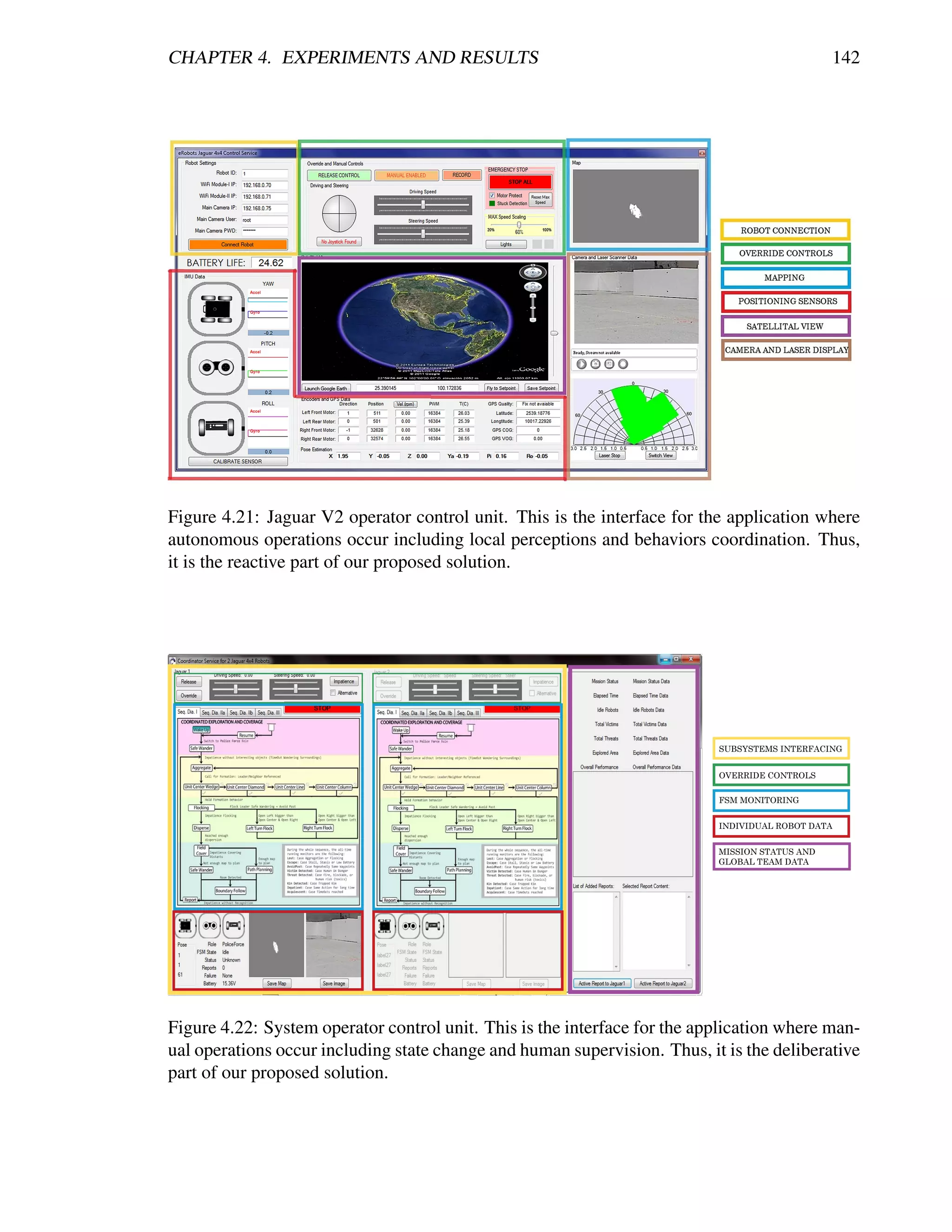
![CHAPTER 4. EXPERIMENTS AND RESULTS 143
Figure 4.23: Template structure for creating and managing reports. Based on [156, 56].
The last step to reach the field tests was to solve the localization problem [94]. Thus, in
order to simplify tests, for the ease of focusing in the performance of our proposed algorithm
and taking into account that even the more sophisticated localization algorithms are not good
enough for the intended real scenarios, we created a very robust localization service using an
external camera that continuously tracks the robots’ pose and messages it to our system-level
OCU. This message is then forwarded to each robot so that both of them can know with good
precision where they are at any moment. Another important thing to mention is that the laser
scanner was limited to 2m and 130◦ field of view, and maximum velocity was set to 0.25m/s,
half of the limit used in the simulations. The environment consisted in an approximate 1:10
scaled version of the simulation scenario so that by using the same metrics (refer to Table 4.2),
expected results were available at hand.](https://image.slidesharecdn.com/dtc-phd-thesis-finalversion-121215102213-phpapp01/75/PhD-Thesis-Coordination-of-Multiple-Robotic-Agents-for-Disaster-and-Emergency-Response-161-2048.jpg)
![CHAPTER 4. EXPERIMENTS AND RESULTS 144
Single Robot Exploration
For single robot exploration experiments, a Jaguar V2 was wirelessly connected to an external
computer, which was receiving the localization data and human operator commands for start-
ing the autonomous operations (subsystem and system elements). The robot was deployed
inside the exploration maze and once the communications link was ready, it started exploring
autonomously. Figure 4.24 shows a screenshot of the robot in the environment, including the
tracking and markers for localization, and a typical autonomous navigation pattern resulting
from our exploration algorithm.
We have stated that maximum speed was set to half the speed of the simulation experi-
ments and the environment area was reduced to approximately 10%. So, the expected results
for over 96% explored area must be around 36 seconds (2 ∗ 180s/10 = 36s, refer to Fig-
ure 4.14(d)). Figure 4.25 demonstrates coherent results for 3 representative runs, validating
our proposed exploration algorithm functionality for single robot operations. It can be appre-
ciated that there are very little flat zones (redundancy) and close results among multiple runs,
referring robustness in the exploration algorithm.
Figure 4.24: Deployment of a Jaguar V2 for single robot autonomous exploration experi-
ments.
Multi-Robot Exploration
For the case of multiple robots, a second robot was included as an additional subsystem el-
ement as refered in section 3.4 and detailed in [72]. Figure 4.26 shows a screenshot of the
typical deployment used during the experiments including the tracking and markers for local-
ization, and an example of navigational pattern when the robots meet along the exploration
task.
This time, considering the average results from the single robot real experiments, the
ideal expected result when using two robots must be around half of the time so as to validate
the algorithm functionality. Figure 4.27(a) shows the results from a representative run includ-
ing robot’s exploration and team’s redundancy. It can be appreciated that full exploration is
achieved almost at half of the time of using only one robot and that redundancy stays very
close to 10%. What is more, Figure 4.27(b) presents an adequate balance in the exploration](https://image.slidesharecdn.com/dtc-phd-thesis-finalversion-121215102213-phpapp01/75/PhD-Thesis-Coordination-of-Multiple-Robotic-Agents-for-Disaster-and-Emergency-Response-162-2048.jpg)
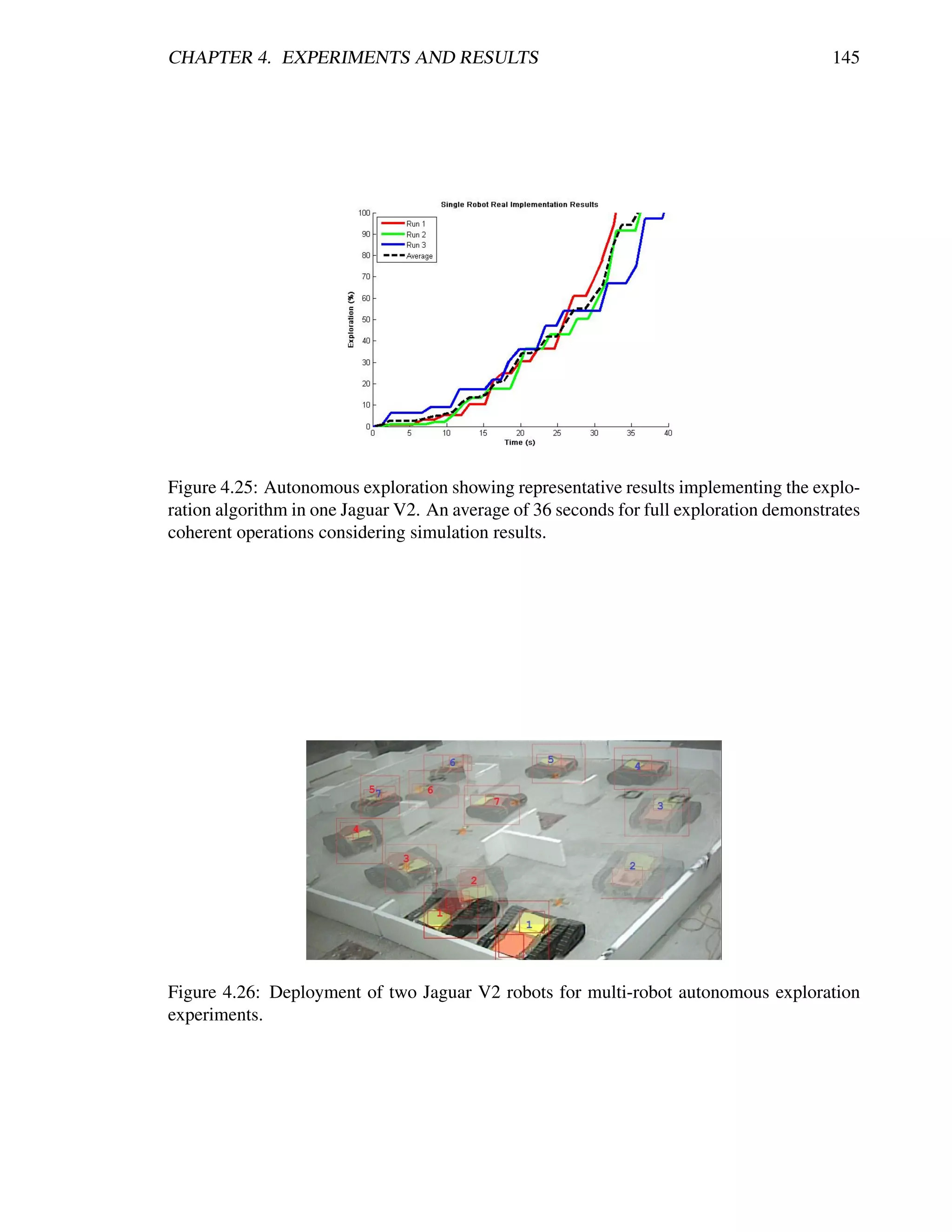
![CHAPTER 4. EXPERIMENTS AND RESULTS 146
quality for each robot. Thus, these results demonstrate the validity of our proposed algorithm
when implemented in a team of multiple robots.
(a) Exploration. (b) Exploration Quality.
Figure 4.27: Autonomous exploration showing representative results for a single run using 2
robots avoiding their own past. An almost half of the time for full exploration when compared
to single robot runs demonstrates efficient resource management. The resultant exploration
quality shows the trend towards perfect balancing between the two robots.
Summarizing these experiments, we have presented an efficient robotic exploration
method using single and multiple robots in 3D simulated environments and in a real testbed
scenario. Our approach achieves similar navigational behavior such as most relevant papers
in literature including [58, 290, 101, 240, 259]. Since there are no standard metrics and
benchmarks, it is a little bit difficult to quantitatively compare our approach with others. In
spite of that, we can conclude that our approach presented very good results with the advan-
tages of using less computational power, coordinating without any bidding/negotiation pro-
cess, and without requiring any sophisticated targeting/mapping technique. Furthermore, we
differ from similar reactive approaches as [21, 10, 114], in that we use a reduced complexity
algorithm with no a-priori knowledge of the environment and without calculating explicit re-
sultant forces. Additionally, we need no static roles neither relay robots so that we are free of
leaving line-of-sight, and we are not depending on every robot’s functionality for task comple-
tion. Moreover, we need no specific world structure and no significant deliberation process,
and thus our algorithm decreases computational complexity from typical O(n2 T ) (n robots,
T frontiers) in deliberative systems and O(n2 ) (nxn grid world) in reactive systems, to O(1)
when robots are dispersed and O(m2 ) whenever m robots need to disperse, and still achieves
efficient exploration times, which is largely due to the fact that all operations are composed of
simple conditional checks and no complex calculations are being done (refer to [71] for the
full details). In short, we use a very simple approach with way reduced operations as shown
in Figure 4.28, and still gather similar and/or better results.
We have demonstrated with these tests that the essence for efficient exploration is to ap-
propriately remember the traversed locations so as to avoid being redundant and time-wasting.
Also, by observing efficient robot dispersion and the effect of avoiding teammates past, we
demonstrated that interference is a key issue to be avoided. Hence, our critical need is a
reliable localization that can enable the robots to appropriately allocate spatial information](https://image.slidesharecdn.com/dtc-phd-thesis-finalversion-121215102213-phpapp01/75/PhD-Thesis-Coordination-of-Multiple-Robotic-Agents-for-Disaster-and-Emergency-Response-164-2048.jpg)
![CHAPTER 4. EXPERIMENTS AND RESULTS 147
Figure 4.28: Comparison between: a) typical literature exploration process and b) our pro-
posed exploration. Clear steps and complexity reduction can be appreciated between sensing
and acting.
(waypoints). In this way, perhaps a mixed strategy of our algorithm with a periodic target
allocation method presented in [43] can result interesting. What is more, the presented explo-
ration strategy could be extended with additional behaviors that can result in a more flexible
and multi-objective autonomous exploration strategy as authors suggest in [25]. The chal-
lenge here resides in defining the appropriate weights for each action so that the emergent
behavior performs efficiently.
Concluding this chapter, we have developed a series of experiments to test the proposed
solution. We have demonstrated the functionality of most of the autonomous behaviors, which
constituted the coordination of the actions developed by the robots. Also, we implemented
an instance of the proposed infrastructure for coupling our MRS and giving it the additional
feature to deliberate and follow a plan, which is supervised and controlled by human operators.
This constituted the coordination of the actions developed by the team of robots. Finally, while
testing the infrastructure, we contributed towards an alternative solution to the autonomous
exploration problem with single and multiple robots. So, the last thing in order to complete
this dissertation is to summarize the contributions and settle the path towards future work.](https://image.slidesharecdn.com/dtc-phd-thesis-finalversion-121215102213-phpapp01/75/PhD-Thesis-Coordination-of-Multiple-Robotic-Agents-for-Disaster-and-Emergency-Response-165-2048.jpg)
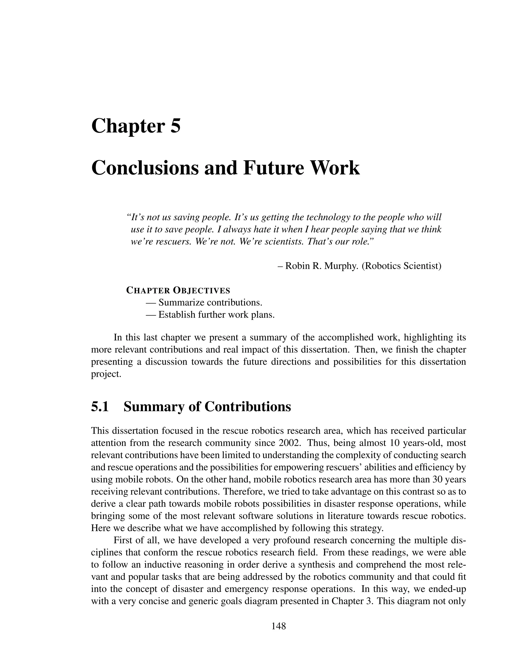
![CHAPTER 5. CONCLUSIONS AND FUTURE WORK 151
demonstrated a methodology for quick setup of robotics simulations and a fast path towards
the real implementations, intending to reduce time costs in the development and deployment
of robotic systems. This resulted in a relevant contribution reported in [70]. Following this
information, the demonstrated functionality of the service-oriented, generic architecture for
the MRS, essentially its scalability and extendibility features, resulted also in another relevant
contribution reported in [72]. Finally, we demonstrated that the essence for efficient explo-
ration is to appropriately remember the traversed locations so as to avoid being redundant
and time-wasting, and not quite to appropriately define the next best target location. This
simplification also resulted in a relevant contribution reported in [71].
5.2 Future Work
Having stated what has been accomplished, it is time to refer the future steps for this work.
Perhaps the best starting point is to refer the possibilities for scalability and extendibility.
About scalability, it will be interesting to test the team architecture using more real robots.
Also, instantiating multiple system elements and interconnecting them so as to have sub-
teams of rescue robots seems like a first step towards much more complex multi-robot sys-
tems. Then, about extendibility, the behavioral architecture of the robots provides a very
simple way of adding more behaviors so as to address different or additional tasks. Also,
if the robots’ characteristics change, the service-oriented design facilitates the process for
adding/modifying behaviors by enabling developers to change focused parts of the software
application. Moreover, thinking of the sequence diagrams and the manual triggering for the
next state, adding more states to the FSM is a simple task. The conflict may come when
transitioning becomes autonomous. So, these characteristics are perhaps the most important
reasons we proposed a nomenclature in Chapter 1 that was not completely exploited in this
dissertation, we intended to provide a clear path towards the applicability of our system for
diverse missions/tasks and using diverse robotic resources.
Another important step towards the future is implementing more complete operations
in more complete/real scenarios. Perhaps the most important reasons for this are time and
laboratory resources. For example, at the beginning of this dissertation we do not even had
a working mobile robot, not to think of a team of them. This situation severely delimits
the work generating a lack of more realistic implementations. Nowadays, the possibilities
for software resources are much more broad as the popularity of the ROS [107] continues
rising, so integrating complex algorithms and even having robust 3D localization systems is
available at hand. So, the challenge resides in setting up a team of mobile robots and start
generating diverse scenarios such as described in [267]. Then, it will be interesting to pursue
relevant goals such as autonomously mapping an environment with characteristics identifying
simulated victims, hazards and damaged kins. Also, a good challenge could be to provide a
general deliberation of the type of aid required according to the victim, hazard or damaged
kin status in order to simulate a response action. In this way, complete rounds of coordinated
search and rescue operations are developed.
Furthermore, in such a young research area, where there are no standardized evaluation
metrics, knowing that a system is performing well is typically qualitatively. Within this disser-
tation we think that evaluating the use of behaviors could lead into learning so as to increase](https://image.slidesharecdn.com/dtc-phd-thesis-finalversion-121215102213-phpapp01/75/PhD-Thesis-Coordination-of-Multiple-Robotic-Agents-for-Disaster-and-Emergency-Response-169-2048.jpg)
![CHAPTER 5. CONCLUSIONS AND FUTURE WORK 152
performance. What is more, in Chapter 1 we even proposed a table of metrics that was not
used because it was thought for complete rounds of coordinated operations. In [268], authors
propose a list with more than 20 possible metrics for evaluating rescue robots’ performance.
Also, the RoboCup Rescue promotes its own metrics and score vectors. So, this turns out
to be a good opportunity area for future work, either implementing some of those metrics
proposed herein or in literature, or even defining new ones that can be turned into standards
or at least provide a generic evaluation method so that the real impact of contributions can
be quantitatively measured. Additionally, once having this evaluators/metrics, systems could
tend to be more autonomous because of their capabilities for learning from what they have
done.
More precise enhancements to this work could be to test the service-oriented property of
dynamic discoverability so as to enhance far reaches exploration [92] by allowing the individ-
ual robots to connect and disconnect automatically according to communication ranges and
dynamically defined rendezvous/aggregation points as in [232]. With this approach, robots
can leave communications range for a certain time and then autonomously come back to con-
nection with more data from the far reaches in the unknown environment. Also, we need to
dispose of the camera-based localization so as to give more precise quantitative evaluations
such as map quality/utility as referred in [155, 6].
In general, there is still a long way in terms of mobility, uncertainty and 3D locations
management. All of these are essential for appropriately trying to coordinate single and multi-
robot systems. Nevertheless, we believe it is by providing these alternative approaches that
we can have a good resource for evaluation purposes that will lead us to address complex
problems and effectively resolve them the way they are. In the end, we think that if more peo-
ple start working with this trend of SOA-based robotics and thus more service independent
providers are active, robotics research could step forward in a faster and more effective way
with more sharing of solutions. We are seeing services as the modules for building complex
and perhaps cognitive robotics systems.
Stated the contributions and the future work, the last thing worth to include is a quote
with which we feel very empathic after having completed this work. It is from Joseph Engel-
berger, the “Father of Robotics”.
“You end up with a tremendous respect for a human being if you’re a roboti-
cist”
– Joseph Engelberger, quoted in Robotics Age, 1985.](https://image.slidesharecdn.com/dtc-phd-thesis-finalversion-121215102213-phpapp01/75/PhD-Thesis-Coordination-of-Multiple-Robotic-Agents-for-Disaster-and-Emergency-Response-170-2048.jpg)
![Appendix A
Getting Deeper in MRS Architectures
In order to better understand group architectures it is important to describe a single robot ar-
chitecture. In this dissertation both concepts refer to the software organization of a robotic
system either for one or multiple robots. So, a robot architecture typically involves multiple
control levels for generating the desired actions from perceptions in order to achieve a given
state or goal. For the ease of understanding we include two relevant examples that demon-
strated functionality, appropriate control organization, and successful tests within different
robotic platforms.
First, there is the development of Alami et al. in [2], which is described as a generic
architecture suitable for autonomy and intelligent robotic control. This architecture is based
upon being task and domain independent and extendible at the robot and behavior levels,
meaning that it can be used for different purposes with different robotic resources. Also,
its modular structure allows for easily developing what is needed for an specific task, thus
enabling designers for simplicity and focus. Figure A.1 shows an illustration of the referred
single robot architecture. Important aspect to notice is the separation of control levels by
blocks concerning differences in operational frequency and complexity. The higher level,
called Decisional, is the one in charge of monitoring and supervising the progress in order to
update mission’s status or modify plans. Then, the Executional level receives the updates from
the supervisor and thus calls for executing the required functional module(s). The Functional
level takes care of the perceptions that are reported to higher levels and used for controlling
the active module(s). This functional modularity enables for dealing with different tasks and
robotic resources. Finally, the Logical and Physical levels represent the electrical signals and
other physical interactions between sensors, actuators and the environment.
Another relevant example designed under the same lineaments is provided by Arkin and
Balch in [12] shown in Figure A.2. Their architecture known as Autonomous Robot Architec-
ture (AuRA) has served as inspiration of plenty other works and implementations requiring
autonomous robots. Perhaps looking less organized than Alami et al.’s work, the idea of hav-
ing multiple control levels is basically the same. It has the equivalent decisional level with the
Cartographer and Planner entities maintaining spatial information and monitoring the status
of the mission and its tasks. Then the executional level comes to be the sequencer trigger-
ing the modules at the functional level called motor schemas (robot behaviors). Also, these
modules can be triggered by sensors’ perceptions including the stored spatial information at
the cartographer block. Thus, a coordinated output from the triggered executional modules is
153](https://image.slidesharecdn.com/dtc-phd-thesis-finalversion-121215102213-phpapp01/75/PhD-Thesis-Coordination-of-Multiple-Robotic-Agents-for-Disaster-and-Emergency-Response-171-2048.jpg)
![APPENDIX A. GETTING DEEPER IN MRS ARCHITECTURES 154
Figure A.1: Generic single robot architecture. Image from [2].](https://image.slidesharecdn.com/dtc-phd-thesis-finalversion-121215102213-phpapp01/75/PhD-Thesis-Coordination-of-Multiple-Robotic-Agents-for-Disaster-and-Emergency-Response-172-2048.jpg)
![APPENDIX A. GETTING DEEPER IN MRS ARCHITECTURES 155
sent to the actuators for working at the physical level and interacting with the environment.
An important additional aspect is the Homeostatic control, which manages the integrity and
relationship among motor schemas by modifying its gains and thus enabling for adaptation
and learning. Finally, there is an explicit division of layers into deliberative and reactive,
this implies specific characteristics of the elements that reside in each of them. This strategy
is known as hybrid architecture for which a complete description can be found at [192],
including purely reactive and purely deliberative approaches.
Figure A.2: Autonomous Robot Architecture - AuRa. Image from [12].
Accordingly, organizing a multiple-robot control system requires to extend the idea of
managing multiple levels of control and functionality in order to conform a group. So, robots
in a given MRS must have their individual architecture such as the ones mentioned above but
coupled in a group architecture. This higher-level structure typically requires for additional
information and control essentially at the decisional and execution control levels, which are
responsible for addressing the task allocation and other resource conflicts. Some historical
examples of representative general purpose architectures for building and controlling multiple](https://image.slidesharecdn.com/dtc-phd-thesis-finalversion-121215102213-phpapp01/75/PhD-Thesis-Coordination-of-Multiple-Robotic-Agents-for-Disaster-and-Emergency-Response-173-2048.jpg)
![APPENDIX A. GETTING DEEPER IN MRS ARCHITECTURES 156
autonomous mobile robots are briefly described below.
NERD HERD [174]. This architecture is one of the first studies in behavior-based
robotics for multiple robots in which simple ballistic behaviors are combined in or-
der to conform more complex team behaviors. Its key features reside in: distributed
and decentralized control, and capabilities for extensibility and scalability. Then, being
practically an evolution of authors’ previous works on behavior-based architectures, the
MURDOCH [111] project modularized not only but control but tasks by implementing
subject-based control strategies. This allowed for having sub-scenarios and directed
communications. The main features of this evolution are: a publish/subscribe based
messaging for task allocation, and negotiations using multi-agent theory (ContractNet)
in multi-robot systems.
Task Control Architecture (TCA) [257]. This work inspired with its ability for con-
current planning, execution and perception for handling several tasks in a parallel way
using multiple robots. Its key features reside in: an efficient resource management
mechanism for task allocation and failure overcoming, task trees for interleaving plan-
ning and execution, and concurrent system status monitoring. Nowadays it is discontin-
ued but authors have created the Distributed Robot Architecture (DIRA) [258] in which
individual autonomy and explicit coordination among multiple robots is achieved via a
3-layered infrastructure: planner, executive and behavioral.
ACTRESS [179]. Considering that every task has its own needs, this work’s design
focuses on distribution, communication protocol, and negotiation, in order to enable
robots to work separately or cooperatively as the task demands. Its key features reside
in: a message protocol designed for distributed/decentralized cooperation, a separa-
tion of problem solving strategies in accordance to leveled communication system, and
multi-robot negotiation at task, cooperation and communication levels.
CEBOT [102]. Having its name from cellular robotics, this work deals with a self-
organizing robotic system that consists of a number of autonomous robots organized in
cells, which can communicate, approach, connect and cooperate with each other. Its
key features reside in: modular structures for collective intelligence and self-organizing
robotic systems, and robot self-recognition used for coordinating efforts towards a goal.
ALLIANCE [221]. Perhaps the most popular and representative work, it is a distributed
fault-tolerant behavior-based cooperative architecture for heterogeneous mobile robots.
It is characterized for implementing a fixed set of motivational controllers for behavior
selection, which at the same time have priorities (subsumption idea from [49]). Con-
trollers use the sensors’ data, communications and modelling of actions between each
robot for better decision making. Its key features reside in: robustness at mission ac-
complishing, fault tolerance by using concepts of robot impatience and acquiescence,
coherent cooperation between robots, and automatic adjustment of controllers’ param-
eters.
M+ System [42]. Taking basis in opportunistic re-scheduling this work is similar to
the TCA in the way of doing concurrent planning. Its key features reside in: robots](https://image.slidesharecdn.com/dtc-phd-thesis-finalversion-121215102213-phpapp01/75/PhD-Thesis-Coordination-of-Multiple-Robotic-Agents-for-Disaster-and-Emergency-Response-174-2048.jpg)
![APPENDIX A. GETTING DEEPER IN MRS ARCHITECTURES 157
concurrently detecting and solving coordination issues, and an effective cooperation
through a “round-robin” mechanism.
A more complete description of some of the mentioned architectures along with other
popular ones such as GOFER [62] and SWARMS [30], can be found in [63, 223, 16]. Also, a
good evaluation of some of them is presented in [218] and [11].](https://image.slidesharecdn.com/dtc-phd-thesis-finalversion-121215102213-phpapp01/75/PhD-Thesis-Coordination-of-Multiple-Robotic-Agents-for-Disaster-and-Emergency-Response-175-2048.jpg)
![Appendix B
Frameworks for Robotic Software
According to [55], in recent years, there has been a growing concern in the robotics com-
munity for developing better software for mobile robots. Issues such as simplicity, con-
sistency, modularity, code reuse, integration, completeness and hardware abstraction have
become key points. With these general objectives in mind, different robotic programming
frameworks have been proposed such as Player [113], ROCI [77], ORCA [47], and more re-
cently ROS [230, 107] and Microsoft Robotics Developer Studio (MSRDS) [234, 135] (an
over-view of some of these frameworks can be found in [55]).
In a parallel path, state of the art trend is to implement Service-Oriented Architec-
tures (SOA) or Service-Oriented Computing (SOC), into the area of robotics. Yu et al. define
SOA in [293] as: “a new paradigm in distributed systems aiming at building loosely-coupled
systems that are extendible, flexible and fit well with existing legacy systems”. SOA promotes
cost-efficient development of complex applications because of leveraging service exchange,
and strongly supporting the concurrent and collaborative design. Thus, applications built
upon this strategy are faster developed, reusable, and upgradeable. From the previously re-
ferred programming frameworks ROS and MSRDS use SOA for developing a networkable
framework for mobile robots giving definition to Service-Oriented Robotics (SOR).
Thus, in a brief timeline, we can accommodate these frameworks and trend as follows:
Before. Robotics software was developed using 0’s and 1’s, assembly and procedural
programming languages, limiting its reusability and being highly delimited to particular
hardware. It was very difficult to upgrade code and give continuity to sophisticated
solutions.
2001 [260, 113]. Player/Stage framework was introduced by Brian Gerkey and person-
nel from the University of Southern California (USC). This system promoted object-
oriented computing (OOC) towards reusable code, modularity, scalability, and ease of
update and maintenance. This implies to instantiate Player modules/classes and connect
them through communication sockets characteristic of the own system. The essential
disadvantage in using Player object-oriented development is that it requires for tightly
coupled classes based on the inheritance relationships. So, developers must have knowl-
edge of application domain and programming. Also, the reuse by inheritance requires
for library functions to be imported at compilation time (only offline upgrading) and are
platform dependent.
158](https://image.slidesharecdn.com/dtc-phd-thesis-finalversion-121215102213-phpapp01/75/PhD-Thesis-Coordination-of-Multiple-Robotic-Agents-for-Disaster-and-Emergency-Response-176-2048.jpg)
![APPENDIX B. FRAMEWORKS FOR ROBOTIC SOFTWARE 159
2003 [77]. ROCI (Remote Objects Control Interface) was introduced by Chaimow-
icz and personnel from the University of Pennsylvania (UPenn) as a self-describing,
objected-oriented programming framework that facilitates the development of robust
applications for dynamic multi-robot teams. It consists in a kernel that coordinates
multiple self-contained modules that serve as building blocks for complex applica-
tions. This was a very nice implementation of hardware abstraction and generic mobile
robotics processes encapsulation, but still resided in object-oriented computing.
2006 [135, 234]. From the private sector, it is released the first version of the Microsoft
Robotics Developer Studio (MSRDS). It was novel framework because it was the first
to introduce the service-oriented systems engineering (SOSE) into robotics research,
but relying on Windows and not being open-source limited its popularity. Nevertheless,
for the first time code reuse happened at the service level. Services have standard in-
terfaces and are published on Internet repository. They are platform-independent and
can be searched and remotely accessed. Service brokerage enables systematic sharing
of services, meaning that service providers can program but do not have to understand
the applications that use their services, while service consumers may use services but
do not have to understand its code deeply. Additionally, the possibility for the services
to be discovered after the application has been deployed, allows an application to be
recomposed at runtime (online upgrading and maintenance).
2007 [47, 48]. This was the time for component-based systems engineering (CBSE)
with the rise of ORCA by Makarenko and personnel from the University of Sidney.
Relying on the same lineaments of Player, ORCA provides with a more useful pro-
gramming approach in terms of modularity and reuse. This framework consists in de-
veloping components under certain pre-defined models as the encapsulated software to
be reused. There is no need to fully understand applications or components code if they
have homogeneous models. So, it is more promising that object-oriented but still lacked
of some important features of service-oriented.
2009 [230, 107]. The Robot Operating System (ROS) started to be hugely promoted
by the designers of Player, essentially by Brian Gerkey and personnel from Willow
Garage. It appeared as an evolution of Player and ORCA offering a framework with
the same advantages from both, plus being more friendly among diverse technologies
and being highly capable of network distribution. This was the first service-oriented
robotics framework that was released as open-source.
Today. MSRDS and ROS are the most popular service-oriented robotic frameworks.
MSRDS is now in its fourth release (RDS 4) but still not open-source and only available
for Windows. ROS has grown incredibly, being supported by a huge robotics commu-
nity a thus providing very large service repositories. Also, both contributions have an
explicit trend to what is now known as cloud robotics [122].
Being more precise, services are mainly a defined class whose instance is a remote
object connected through a proxy, in order to reach a desired behavior. Then, a service-
oriented architecture is essentially a collection of services. In robotics, these services are
mainly (but not limited to): hardware components such as drivers for sensors and actuators;](https://image.slidesharecdn.com/dtc-phd-thesis-finalversion-121215102213-phpapp01/75/PhD-Thesis-Coordination-of-Multiple-Robotic-Agents-for-Disaster-and-Emergency-Response-177-2048.jpg)
![APPENDIX B. FRAMEWORKS FOR ROBOTIC SOFTWARE 160
software components such as user interfaces, orchestrators (robot control algorithms), and
repositories (databases); or aggregations referring to sensor-fusion, filtering and related tasks.
So, the main advantage of this implementation resides in that there are pre-developed services
that exist in repositories that developers can use for their specific application. Also, if a service
is not available, the developer can build its own and contribute to the community. In such way,
SOR is composed of independent providers all around the globe, allowing to build robotics
software in distributed teams with large code bases and without a single person crafting the
entire software, enabling faster setup and easier development of complex applications [82].
Other benefits on using SOR are the following [4]:
• Manageability of heterogeneity by standardizing a service structure.
• Ease of integrating new robots to the network by self-identifying without reprogram-
ming or reconfiguring (self-discoverable capabilities).
• An inherent negotiation structure where every robot can offer its services for interaction
and ask for other robots’ running services.
• Fully meshed data interchange for robots in the network.
• Ability to handle communication disruption where a disconnected out-of-communication-
range robot can resynchronize and continue communications when connection is recov-
ered.
• Mechanisms for making reusability more direct than in traditional approaches, enabling
for using the same robot’s code for different applications.
On the other hand, the well-known disadvantage of implementing SOR is the reduced
efficiency when compared to classical software solutions because of the additional layer of
standard interfaces, which are necessary to guarantee concurrent coordination among ser-
vices [73, 82]. The crucial effect resides in the communications overhead among networked
services, having an important impact in real-time performance. Fortunately for us, nowa-
days the run-time overhead is not as important as it was because modern hardware is fast and
cheap [218].
Summarizing, in Table B.1 we synthesize the main characteristics of the different pro-
gramming approaches that are popular among the most relevant frameworks for robotic soft-
ware.](https://image.slidesharecdn.com/dtc-phd-thesis-finalversion-121215102213-phpapp01/75/PhD-Thesis-Coordination-of-Multiple-Robotic-Agents-for-Disaster-and-Emergency-Response-178-2048.jpg)
![Table B.1: Comparison among different software systems engineering techniques [219, 46, 82, 293, 4].
Object-Oriented Component-Based Service-Oriented
√ √ √
Reusability √ √ √
Modularity
Module unit library component
√ service
√
Management of complexity √ √
Shorten deployment time √ √ √
Assembly and integration of parts √ √
Loosely coupling √ √
Tightly coupling √ √
Stateless √ √ √
Stateful √
Platform independent √
Protocols independent √
Devices independent √
Technology independent √
Internet search/discovery √ √
Easy maintenance and upgrades √ √
Self-describing modules √ √
Self-contained modules
APPENDIX B. FRAMEWORKS FOR ROBOTIC SOFTWARE
√ √
Feasible organization √
Feasible module sharing/substitutability √ √
Feasible information exchange among modules √
Run-time dynamic discovery/upgrade (online composition) √ √ √
Compilation-time static module discovery (offline composition) √ √
White-box encapsulation √ √
Black-box encapsulation √
Heterogeneous providers/composition of modules √
Developers may not know the application
161](https://image.slidesharecdn.com/dtc-phd-thesis-finalversion-121215102213-phpapp01/75/PhD-Thesis-Coordination-of-Multiple-Robotic-Agents-for-Disaster-and-Emergency-Response-179-2048.jpg)
![Appendix C
Set of Actions Organized as Robotic
Behaviors
Classification, types and description of behaviors are essentially based upon [172, 175, 11,
192] Ballistic control type implies a fixed sequence of steps, while servo control refers to
“in-flight” corrections for a closed-loop control.
Table C.1: Wake up behavior.
Behavior Name (ID): Wake up (WU)
Literature aliases: Initialize, Setup, Ready, Start, Deploy
Classification: Protective
Control type: Ballistic
Inputs: -
Enable motors
Initialize state variables
Actions: Set Police Force (PF) role
Call for Safe Wander behavior
Releasers: Initial deployment
Inhibited by: Resume, Safe Wander
Sequence diagram operations: Initialization stage
Main references: -
162](https://image.slidesharecdn.com/dtc-phd-thesis-finalversion-121215102213-phpapp01/75/PhD-Thesis-Coordination-of-Multiple-Robotic-Agents-for-Disaster-and-Emergency-Response-180-2048.jpg)
![APPENDIX C. SET OF ACTIONS ORGANIZED AS ROBOTIC BEHAVIORS 163
Table C.2: Resume behavior.
Behavior Name (ID): Resume (RES)
Literature aliases: Restart, Reset
Classification: Protective
Control type: Ballistic
Inputs: -
Re-initialize state variables
Set Police Force (PF) role
Actions:
Call for Safe Wander behavior
Releasers: Finished reporting or updating report
Inhibited by: Safe Wander
Sequence diagram operations: Initialization stage, Re-establishing stage
Main references: -
Table C.3: Wait behavior.
Behavior Name (ID): Wait (WT)
Literature aliases: Halt, Queue, Stop
Classification: Cooperative, Protective
Control type: Servo
Inputs: Number of lost kins
Stop motors until every robot in Police
Actions: Force (PF) role is docked and holding
formation
Releasers: Lost robot
Inhibited by: Hold Formation, Flocking ready
Sequence diagram operations: Flocking surroundings stage
Main references: [167]](https://image.slidesharecdn.com/dtc-phd-thesis-finalversion-121215102213-phpapp01/75/PhD-Thesis-Coordination-of-Multiple-Robotic-Agents-for-Disaster-and-Emergency-Response-181-2048.jpg)
![APPENDIX C. SET OF ACTIONS ORGANIZED AS ROBOTIC BEHAVIORS 164
Table C.4: Handle Collision behavior.
Behavior Name (ID): Handle Collision (HC)
Literature aliases: Avoid Obstacles
Classification: Protective
Control type: Servo
Inputs: Distance and obstacle type
Avoid sides
Actions: Avoid corners
Avoid kins
Releasers: Always on
Inhibited by: Wall Follow, Inspect, Aid Blockade
Sequence diagram operations: All
Main references: [11, 236, 278]
Table C.5: Avoid Past behavior.
Behavior Name (ID): Avoid Past (AP)
Literature aliases: Motion Planner, Waypoint Manager
Classification: Explorative
Control type: Servo
Inputs: Waypoints list
Evaluate neighbor waypoints
Add waypoint to waypoint list
Actions:
Increase waypoint visit count
Steer away from most visited waypoint
Releasers: Field Cover and visited waypoint
Inhibited by: Seek, Wall Follow, Path Planning, Report
Sequence diagram operations: Covering distants stage, Approaching stage
Main references: [21]](https://image.slidesharecdn.com/dtc-phd-thesis-finalversion-121215102213-phpapp01/75/PhD-Thesis-Coordination-of-Multiple-Robotic-Agents-for-Disaster-and-Emergency-Response-182-2048.jpg)
![APPENDIX C. SET OF ACTIONS ORGANIZED AS ROBOTIC BEHAVIORS 165
Table C.6: Locate behavior.
Behavior Name (ID): Locate (LOC)
Literature aliases: Adjust Heading
Classification: Explorative, Protective
Control type: Servo
Inputs: Current heading, goal type and location
Identify goal type
Actions: Calculate goal heading
Steer until achieving desired heading
Releasers: Safe Wander or Field Cover and wander rate
Inhibited by: Handle Collision, Victim/Threat/Kin
Sequence diagram operations: Covering distants stage
Main references: [7]
Table C.7: Drive Towards behavior.
Behavior Name (ID): Drive Towards (DT)
Literature aliases: Arrive, Cruise, Approach
Classification: Explorative
Control type: Servo
Inputs: Distance to goal
Determine zone according to distance
Actions:
Adjust driving velocity
Releasers: Approach
Inhibited by: Inspect, Handle Collision
Sequence diagram operations: Approaching stage
Main references: [23]](https://image.slidesharecdn.com/dtc-phd-thesis-finalversion-121215102213-phpapp01/75/PhD-Thesis-Coordination-of-Multiple-Robotic-Agents-for-Disaster-and-Emergency-Response-183-2048.jpg)
![APPENDIX C. SET OF ACTIONS ORGANIZED AS ROBOTIC BEHAVIORS 166
Table C.8: Safe Wander behavior.
Behavior Name (ID): Safe Wander (SW)
Literature aliases: Random Explorer
Classification: Explorative
Control type: Ballistic
Inputs: Distance to objects nearby
Move forward
Locate open area
Actions:
Handle collision
Avoid Past
Releasers: Wake up, Resume, or Field Cover ended
Inhibited by: Aggregate, Wall Follow, Report, Victim/Threat/Kin
Sequence diagram operations: Initialization stage, Covering distants stage
Main references: [175]
Table C.9: Seek behavior.
Behavior Name (ID): Seek (SK)
Literature aliases: Homing, Attract, GoTo, Local Path Planner
Classification: Appetitive, Explorative
Control type: Servo
Inputs: Goal position (X,Y)
Create Vector Field Histogram
Actions:
Motion control towards goal
Releasers: Aggregate, Hold Formation, Seeking
Inhibited by: Inspect, Disperse, Victim/Threat/Kin
Approaching, Rendezvous, and
Sequence diagram operations: Flocking Surroundings stages
Main references: [171, 175, 236, 41]](https://image.slidesharecdn.com/dtc-phd-thesis-finalversion-121215102213-phpapp01/75/PhD-Thesis-Coordination-of-Multiple-Robotic-Agents-for-Disaster-and-Emergency-Response-184-2048.jpg)
![APPENDIX C. SET OF ACTIONS ORGANIZED AS ROBOTIC BEHAVIORS 167
Table C.10: Path Planning behavior.
Behavior Name (ID): Path Planning (PP)
Literature aliases: Motion Planner
Classification: Explorative
Control type: Servo
Inputs: Goal position (X,Y)
Determine the wayfront propagation
Actions: List target waypoints to goal
Seek to each waypoint
Releasers: Field Cover ended plus enough 2D map to plan
Inhibited by: Safe Wander, Wall Follow, Report, Victim/Threat/Kin
Sequence diagram operations: Covering distants stage
Main references: [10, 154, 224]
Table C.11: Aggregate behavior.
Behavior Name (ID): Aggregate (AG)
Literature aliases: Cohesion, Dock, Rendezvous
Classification: Appetitive
Control type: Servo
Inputs: Police Force robots’ poses
Determine centroid of all PF robots’ poses
Actions:
Seek towards centroid
Releasers: Safe Wander, Resume, Call for formation
Inhibited by: Disperse, Victim/Threat/Kin
Sequence diagram operations: Rendezvous stage
Main references: [171, 175, 23]
Table C.12: Unit Center Line behavior.
Behavior Name (ID): Unit Center Line (UCL)
Literature aliases: Form Line
Classification: Cooperative
Control type: Servo
Inputs: Robot ID and number of PF robots
Aggregate
Actions: Determine pose according to line formation
Seek position
Releasers: Aggregation/Rendezvous, Structured Exploration
Inhibited by: Hold Formation, Disperse, Victim/Threat/Kin
Sequence diagram operations: Rendezvous and Flocking surroundings stages
Main references: [23]](https://image.slidesharecdn.com/dtc-phd-thesis-finalversion-121215102213-phpapp01/75/PhD-Thesis-Coordination-of-Multiple-Robotic-Agents-for-Disaster-and-Emergency-Response-185-2048.jpg)
![APPENDIX C. SET OF ACTIONS ORGANIZED AS ROBOTIC BEHAVIORS 168
Table C.13: Unit Center Column behavior.
Behavior Name (ID): Unit Center Column (UCC)
Literature aliases: Form Column
Classification: Cooperative
Control type: Servo
Inputs: Robot ID and number of PF robots
Aggregate
Actions: Determine pose according to column formation
Seek position
Releasers: Aggregation/Rendezvous, Structured Exploration
Inhibited by: Hold Formation, Disperse, Victim/Threat/Kin
Sequence diagram operations: Rendezvous and Flocking surroundings stages
Main references: [23]
Table C.14: Unit Center Diamond behavior.
Behavior Name (ID): Unit Center Diamond (UCD)
Literature aliases: Form Diamond
Classification: Cooperative
Control type: Servo
Inputs: Robot ID and number of PF robots
Aggregate
Actions: Determine pose according to diamond formation
Seek position
Releasers: Aggregation/Rendezvous, Structured Exploration
Inhibited by: Hold Formation, Disperse, Victim/Threat/Kin
Sequence diagram operations: Rendezvous and Flocking surroundings stages
Main references: [23]](https://image.slidesharecdn.com/dtc-phd-thesis-finalversion-121215102213-phpapp01/75/PhD-Thesis-Coordination-of-Multiple-Robotic-Agents-for-Disaster-and-Emergency-Response-186-2048.jpg)
![APPENDIX C. SET OF ACTIONS ORGANIZED AS ROBOTIC BEHAVIORS 169
Table C.15: Unit Center Wedge behavior.
Behavior Name (ID): Unit Center Wedge (UCW)
Literature aliases: Form Wedge
Classification: Cooperative
Control type: Servo
Inputs: Robot ID and number of PF robots
Aggregate
Actions: Determine pose according to wedge formation
Seek position
Releasers: Aggregation/Rendezvous, Structured Exploration
Inhibited by: Hold Formation, Disperse, Victim/Threat/Kin
Sequence diagram operations: Rendezvous and Flocking surroundings stages
Main references: [23]
Table C.16: Hold Formation behavior.
Behavior Name (ID): Hold Formation (HF)
Literature aliases: Align, Keep Pose
Classification: Cooperative
Control type: Servo
Inputs: Position to hold
Seek position
Actions:
Call for Lost
Releasers: Docked in formation, Flocking ready
Inhibited by: Lost, Disperse, Victim/Threat/Kin
Sequence diagram operations: Rendezvous and Flocking surroundings stages
Main references: [23, 271, 208]
Table C.17: Lost behavior.
Behavior Name (ID): Lost (L)
Literature aliases: Undocked, Unaligned
Classification: Cooperative
Control type: Servo
Inputs: Position to hold
Message of lost robot
Actions:
Seek towards position
Releasers: Hold formation failed
Inhibited by: Disperse, Hold Formation, Flocking ready
Sequence diagram operations: Flocking surroundings stage
Main references: [167]](https://image.slidesharecdn.com/dtc-phd-thesis-finalversion-121215102213-phpapp01/75/PhD-Thesis-Coordination-of-Multiple-Robotic-Agents-for-Disaster-and-Emergency-Response-187-2048.jpg)
![APPENDIX C. SET OF ACTIONS ORGANIZED AS ROBOTIC BEHAVIORS 170
Table C.18: Flocking behavior.
Behavior Name (ID): Flock (FL)
Literature aliases: Joint Explore, Sweep Cover, Structured Exploration
Classification: Cooperative
Control type: Ballistic
Inputs: Robot ID
Determine the leader
Actions: If leader, then Safe Wander
If not leader, then Hold Formation
Releasers: Flocking ready
Inhibited by: Disperse, Victim/Threat/Kin
Sequence diagram operations: Flocking surroundings stage
Main references: [105, 171, 23, 236, 235]](https://image.slidesharecdn.com/dtc-phd-thesis-finalversion-121215102213-phpapp01/75/PhD-Thesis-Coordination-of-Multiple-Robotic-Agents-for-Disaster-and-Emergency-Response-188-2048.jpg)
![APPENDIX C. SET OF ACTIONS ORGANIZED AS ROBOTIC BEHAVIORS 171
Table C.19: Disperse behavior.
Behavior Name (ID): Disperse (DI)
Literature aliases: Separate
Classification: Appetitive
Control type: Servo
Inputs: Police Force robots’ poses
Locate PF robots’ centroid
Actions: Turn 180 degrees away
Move forward until comfort zone
Releasers: Field Cover, Flocking ended
Inhibited by: Dispersion ready, Victim/Threat/Kin
Sequence diagram operations: Covering distants stage
Main references: [171, 23]
Table C.20: Field Cover behavior.
Behavior Name (ID): Field Cover (FC)
Literature aliases: Survey, Patrol, Swipe
Classification: Cooperative
Control type: Ballistic
Inputs: Waypoints list
Disperse
Actions: Locate open area
Safe Wander
Releasers: Dispersion ready
Inhibited by: Path Plan, Wall Follow, Report, Victim/Threat/Kin
Sequence diagram operations: Covering distants stage
Main references: [58]](https://image.slidesharecdn.com/dtc-phd-thesis-finalversion-121215102213-phpapp01/75/PhD-Thesis-Coordination-of-Multiple-Robotic-Agents-for-Disaster-and-Emergency-Response-189-2048.jpg)
![APPENDIX C. SET OF ACTIONS ORGANIZED AS ROBOTIC BEHAVIORS 172
Table C.21: Wall Follow behavior.
Behavior Name (ID): Wall Follow (WF)
Literature aliases: Boundary Follow
Classification: Explorative
Control type: Servo
Inputs: Laser readings, side to follow
Search for wall
Actions:
Move forward
Releasers: Room detected
Inhibited by: Report, Victim/Threat/Kin
Sequence diagram operations: Covering distants stage
Main references: -
Table C.22: Escape behavior.
Behavior Name (ID): Escape (ESC)
Literature aliases: Stuck, Stall, Stasis, Low Battery, Damage
Classification: Protective
Control type: Ballistic
Inputs: Odometry data, Battery level
If odometry anomaly, Locate open area
If located open area, Translate safe distance
Actions:
If low battery, Seek home
If no improvement, set Trapped role
Releasers: Odometry anomaly, low battery
Inhibited by: Trapped role
Sequence diagram operations: All
Main references: [224]
Table C.23: Report behavior.
Behavior Name (ID): Report (REP)
Literature aliases: Communicate, Message
Classification: Cooperative
Control type: Ballistic
Inputs: Report content
Generate report template message using content
Actions:
Send it to central station
Releasers: Victim/Threat/Kin inspected or aided
Inhibited by: Resume, Give Aid
Sequence diagram operations: All
Main references: [156, 272, 56, 222, 168]](https://image.slidesharecdn.com/dtc-phd-thesis-finalversion-121215102213-phpapp01/75/PhD-Thesis-Coordination-of-Multiple-Robotic-Agents-for-Disaster-and-Emergency-Response-190-2048.jpg)
![APPENDIX C. SET OF ACTIONS ORGANIZED AS ROBOTIC BEHAVIORS 173
Table C.24: Track behavior.
Behavior Name (ID): Track (TRA)
Literature aliases: Pursue, Hunt
Classification: Perceptive, Appetitive
Control type: Servo
Inputs: Object to track
Locate attribute/object
Hold attribute in line of sight (AVM or SURF)
Actions: Drive Towards
Handle Collisions
Call for Inspect
Releasers: Victim/Threat found
Inhibited by: Inspect, Report
Sequence diagram operations: Approaching/Pursuing stage
Main references: [278], AVM tracking [97], SURF tracking [26]
Table C.25: Inspect behavior.
Behavior Name (ID): Inspect (INS)
Literature aliases: Analyze, Orbit, Extract Features
Classification: Perceptive
Control type: Ballistic
Inputs: Object to inspect
Predefined navigation routine surrounding object
Actions: Report attributes
Wait for central station decision
Releasers: Object to inspect reached
Inhibited by: Report, Give Aid
Sequence diagram operations: Analysis/Examination stage
Main references: -](https://image.slidesharecdn.com/dtc-phd-thesis-finalversion-121215102213-phpapp01/75/PhD-Thesis-Coordination-of-Multiple-Robotic-Agents-for-Disaster-and-Emergency-Response-191-2048.jpg)
![APPENDIX C. SET OF ACTIONS ORGANIZED AS ROBOTIC BEHAVIORS 174
Table C.26: Victim behavior.
Behavior Name (ID): Victim (VIC)
Literature aliases: Human Recognition, Face Recognition
Classification: Supportive
Control type: Ballistic
Inputs: Object attributes
Evaluate reported objects
Actions: If not reported, switch to Ambulance Team role
Call for Seek/Track, Approach, Inspect routine
Releasers: Visual recognition of victim
Inhibited by: Resume, Give Aid
Sequence diagram operations: Triggering recognition stage
Main references: [90, 224, 32, 20, 207]
Table C.27: Threat behavior.
Behavior Name (ID): Threat (TH)
Literature aliases: Threat Detected, Fire Detected, Hazmat Found
Classification: Supportive
Control type: Ballistic
Inputs: Object attributes
Evaluate reported objects
Actions: If not reported, switch to Firefighter Brigade role
Call for Seek/Track, Approach, Inspect routine
Releasers: Visual recognition of threat
Inhibited by: Resume, Give Aid
Sequence diagram operations: Triggering recognition stage
Main references: [224, 32, 116, 20]](https://image.slidesharecdn.com/dtc-phd-thesis-finalversion-121215102213-phpapp01/75/PhD-Thesis-Coordination-of-Multiple-Robotic-Agents-for-Disaster-and-Emergency-Response-192-2048.jpg)
![APPENDIX C. SET OF ACTIONS ORGANIZED AS ROBOTIC BEHAVIORS 175
Table C.28: Kin behavior.
Behavior Name (ID): Kin (K)
Literature aliases: Trapped Kin, Endangered Kin
Classification: Supportive
Control type: Ballistic
Inputs: Object attributes
Evaluate reported objects
Actions: If not reported, switch to Team Rescuer role
Call for Seek, Inspect routine
Releasers: Message of endangered kin
Inhibited by: Resume, Give Aid
Sequence diagram operations: Triggering recognition stage
Main references: [224]
Table C.29: Give Aid behavior.
Behavior Name (ID): Give Aid (GA)
Literature aliases: Help, Support, Relief
Classification: Supportive
Control type: Ballistic
Inputs: Object attributes and robot role
Determine appropriate aid
Actions: If available/possible, call for corresponding Aid-
If unavailable, call for Report
Releasers: Central station accepts to evaluate aid
Inhibited by: Aid- , Report
Sequence diagram operations: Aid determining stage
Main references: [80, 224, 204]](https://image.slidesharecdn.com/dtc-phd-thesis-finalversion-121215102213-phpapp01/75/PhD-Thesis-Coordination-of-Multiple-Robotic-Agents-for-Disaster-and-Emergency-Response-193-2048.jpg)
![APPENDIX C. SET OF ACTIONS ORGANIZED AS ROBOTIC BEHAVIORS 176
Table C.30: Aid- behavior.
Behavior Name (ID): Aid- (Ax)
Literature aliases: -
Classification: Supportive
Control type: Servo
Inputs: Object attributes
Include the possibility of rubble removal, fire
extinguising, displaying info, enabling two-way
Actions:
communications, send alerts, transporting object,
or even in-situ medical assessment
Releasers: Aid determined
Inhibited by: Aid finished or failed, Report
Sequence diagram operations: Support and Relief stage
Main references: [224, 204, 20, 268]
Table C.31: Impatient behavior.
Behavior Name (ID): Impatient (IMP)
Literature aliases: Timeout
Classification: Cooperative
Control type: Ballistic
Inputs: Current behavior, robot role, current global task
Increase impatience count
Actions:
Call for Acquiescence
Releasers: Manual triggering, reached timeout
Inhibited by: Acquiescent
Sequence diagram operations: All
Main references: [221]
Table C.32: Acquiescent behavior.
Behavior Name (ID): Acquiescent (ACQ)
Literature aliases: Relinquish
Classification: Cooperative
Control type: Ballistic
Inputs: Current behavior, robot role, current global task
Determine next behavior or state
Actions:
Change to new behavior
Releasers: Impatient
Inhibited by: -
Sequence diagram operations: All
Main references: [221]](https://image.slidesharecdn.com/dtc-phd-thesis-finalversion-121215102213-phpapp01/75/PhD-Thesis-Coordination-of-Multiple-Robotic-Agents-for-Disaster-and-Emergency-Response-194-2048.jpg)
![APPENDIX C. SET OF ACTIONS ORGANIZED AS ROBOTIC BEHAVIORS 177
Table C.33: Unknown behavior.
Behavior Name (ID): Unknown (U)
Literature aliases: Failure, Damage, Malfunction, Trapped
Classification: Protective
Control type: Ballistic
Inputs: Error type
Stop motors
Actions:
Report
Releasers: Failure detected, Escape failed
Inhibited by: Manual triggering
Sequence diagram operations: All
Main references: [224]](https://image.slidesharecdn.com/dtc-phd-thesis-finalversion-121215102213-phpapp01/75/PhD-Thesis-Coordination-of-Multiple-Robotic-Agents-for-Disaster-and-Emergency-Response-195-2048.jpg)
![Appendix D
Field Cover Behavior Composition
For this behavior we focus on the very basis of robotic exploration according to Yamauchi:
“Given what you know about the world, where should you move to gain as much new informa-
tion as possible?” [291]. In this way, we propose a behavior-based approach for multi-robot
exploration that puts together the simplicity and good performance of purely reactive control
with some of the benefits of deliberative approaches, regarding the ability of reasoning about
the environment.
The proposed solution makes use of four different robotic behaviors and a resultant
emergent behavior.
D.1 Behavior 1: Avoid Obstacles
The first behavior is the Avoid Obstacles. This protective behavior considers 3 particu-
lar conditions for maintaining the robot’s integrity. The first condition is to check for possible
corners in order to avoid getting stuck or spending unnecessary time there because of the
avoiding the past effect. The methodology for detecting the corners is to check for the dis-
tance measurements of 6 fixed laser points for each side (left, right, front) and according to
their values determine if there is a high probability of being a corner. There are multiple cases
considering corners: 1) if the corner has been detected at the left, then robot must turn right
with an equivalent steering speed according to the angle where the corner has been detected;
2) if it has been detected at the right, then robot must turn left with an equivalent steering
speed according to the angle where the corner has been detected; and 3) if the corner has
been detected at the front, then robot must turn randomly to right or left with an equivalent
steering speed according to the distance towards the corner. The next condition is to keep a
safe distance to obstacles, steering away from them if it is still possible to avoid collision, or
translating a fixed safe distance if obstacles are already too close. The third and final condi-
tion is to avoid teammates so as not to interfere or collide with them. Most of the times this is
done by steering away from the robot nearby, but other times we found it useful to translate a
fixed distance. It is worth to refer that the main reason for differentiating between teammates
and moving obstacles resides in that we can control a teammate so as to make a more efficient
avoidance. Pseudocode referring these operations is presented in Algorithm 1.
178](https://image.slidesharecdn.com/dtc-phd-thesis-finalversion-121215102213-phpapp01/75/PhD-Thesis-Coordination-of-Multiple-Robotic-Agents-for-Disaster-and-Emergency-Response-196-2048.jpg)
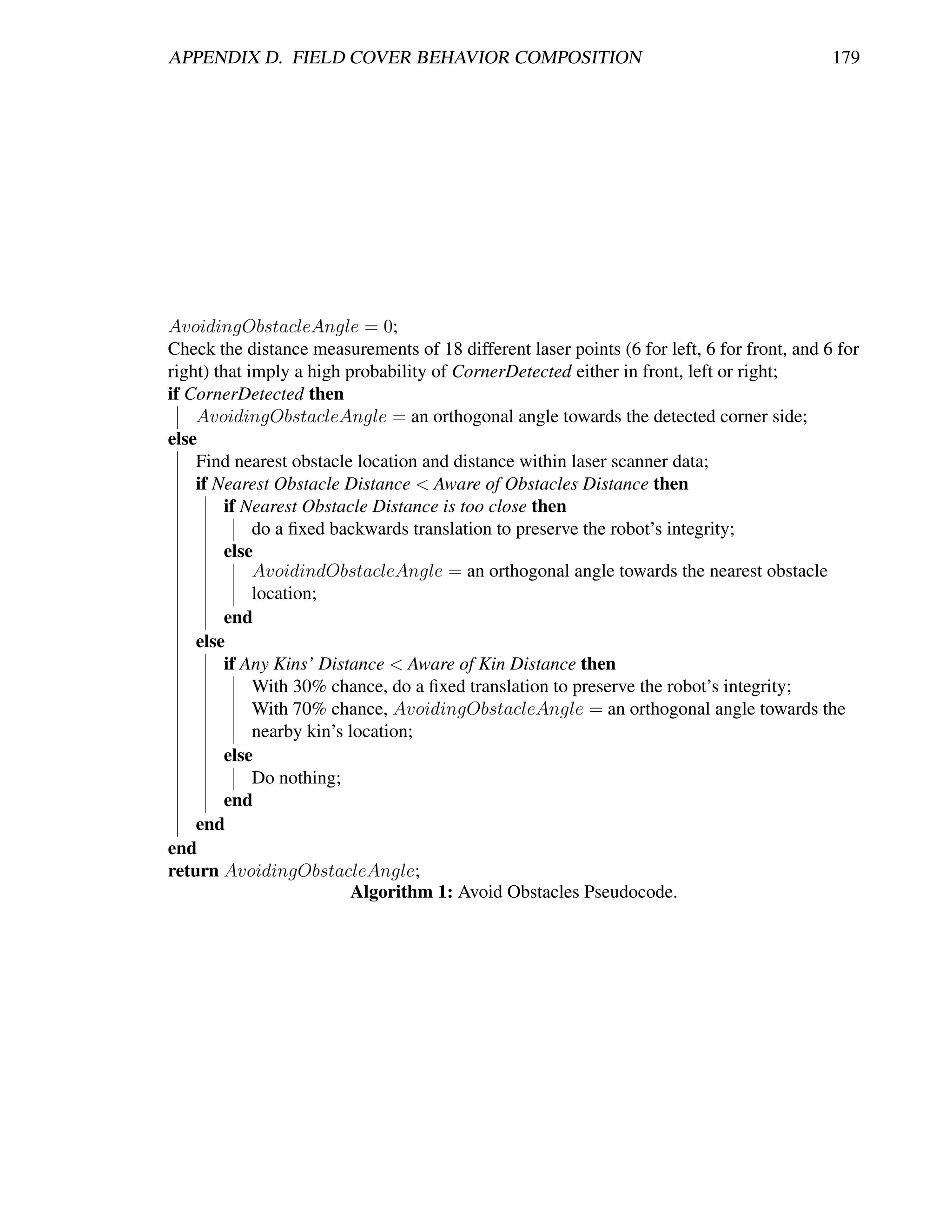
![APPENDIX D. FIELD COVER BEHAVIOR COMPOSITION 180
D.2 Behavior 2: Avoid Past
The second behavior is for gathering the newest locations: the Avoid Past. This kind of
explorative behavior was introduced by Balch and Arkin in [21] as a mechanism for avoiding
local minima when navigating towards a goal. It was proposed also for autonomous explo-
ration, but it leaded to a constant conflict of getting stuck in corners, therefore the importance
of anticipated corners avoidance in previous behavior. Additionally, the algorithm required
a static discrete environment grid which must be known at hand, which is not possible for
unknown environments. Furthermore, the complexity in order to compute the vector so as
to derive the updated potential field goes up to O(n2 ) for a supposed nxn grid world. Thus,
the more the resolution of the world (smaller grid-cell size) the more computational power
required. Nevertheless, it is from them and from the experience presented in works such as
in [114], that we considered the idea of enhancing reactivity with local spatial memory so as
to produce our own algorithm.
Our Avoid Past does not get the aforementioned problems. First of all, because
of the simple recognition of corners provided within the Avoid Obstacles, we never get stuck
neither spend unnecessary time there. Next, we are using a hashtable data structure for storing
the robot traversed locations (the past). Basically, concerning the size of the used robots, we
consider an implicit 1-meter grid discretization in which the actual robot position (x,y) is
rounded. We then use a fixed number of digits, for x and y, to create the string “xy” as a key
to the hashtable, that is queried and updated whenever the robot visits that location. Thus,
each location has a unique key, turning the hashtable to be able to look up for an element
with complexity O(1), which is a property of this data structure. It is important to mention
that this discretization can accommodate imperfect localization within the grid resolution and
we do not require any a-priori knowledge of the environment. To set the robot direction, a
steering speed reaction is computed by evaluating the number of visits of the 3-front neighbor
(x,y) locations in the hashtable. These 3 neighbors depend on the robot orientation according
to 8 possible 45◦ heading cases (ABC, BCD, CDE, DEF, EFG, FGH, GHA, HAB) shown
in Figure D.1. It is important to notice, that evaluating 3 neighbors without a hashtable data
structure will turn our location search complexity into O(n) for n locations, where n is an
increasing number as exploration goes by, thus the hashtable is very helpful. Additionally,
we keep all operations with the 3 neighbors within IF-THEN conditional checks leveraging
simplicity and reduced computational cost. Pseudocode referring these operations is presented
in Algorithm 2.
D.3 Behavior 3: Locate Open Area
The third behavior, named Locate Open Area, is composed of an algorithm for locating
the largest open area in which the robot’s width fits. It consists of a wandering rate that
represents the frequency at which the robot must locate the open area, which is basically the
biggest surface without obstacles being perceived by the laser scanner. So, if this behavior is
triggered the robot stops moving and turns towards the open area to continue its navigation.
This behavior represents the wandering factor of our exploration algorithm and resulted very
important for the obtained performance. For example, when the robot enters a small room, it](https://image.slidesharecdn.com/dtc-phd-thesis-finalversion-121215102213-phpapp01/75/PhD-Thesis-Coordination-of-Multiple-Robotic-Agents-for-Disaster-and-Emergency-Response-198-2048.jpg)
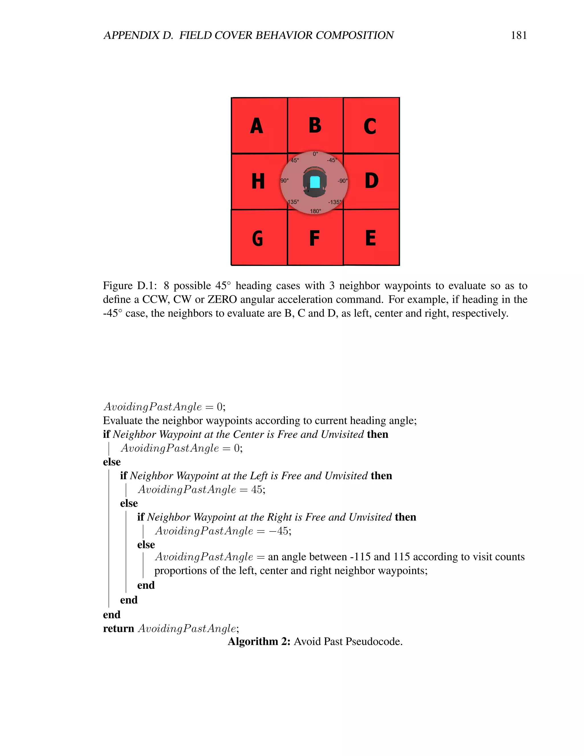
![APPENDIX D. FIELD COVER BEHAVIOR COMPOSITION 182
tends to be trapped within its past and the corners of the room, if this happens there is still the
chance of locating the exit as the largest open area and escape from this situation in order to
continue exploring. Pseudocode referring these operations is presented in Algorithm 3.
Find the best heading as the middle laser point of a set of consecutive laser points that fit a
safe width for the robot to traverse, and have the biggest distance measurements;
if DistanceT oBestHeading > Saf eDistance then
Do a turning action towards the determined best heading;
else
Do nothing;
end
Algorithm 3: Locate Open Area Pseudocode.
D.4 Behavior 4: Disperse
The next operation is our cooperative behavior called Disperse. This behavior is inspired
by the work of Matari´ [173]. It activates just in the case two or more robots get into a prede-
c
fined comfort zone. Thus, for m robots near in a pool of n robots, where m ≤ n, we call for
simple conditional checks so as to derive an appropriate dispersion action. It must be stated
that this operation serves as the coordination mechanism for efficiently spreading the robots
as well as for avoiding teammates interference. Even though it is not active at all times, if (and
only if) it is triggered, a temporal O(m2 ) complexity is added to the model, which is finally
dropped when the m involved robots have dispersed. The frequency of activation depends
on the number of robots and the relative physical dimensions between robots and the envi-
ronment, which is important before deployment decisions. Actions concerning this behavior
include steering away from the nearest robot if m = 1, or steer away from the centroid of the
group of m > 1; then a move forward action is triggered until reaching out the defined near
area or comfort zone. It is important to clarify that this behavior firstly checks for any possible
avoiding obstacles action, which if exists then the dispersion effect is overridden until robot’s
integrity is ensured. Pseudocode referring these operations is presented in Algorithm 4.
D.5 Emergent Behavior: Field Cover
Last, with a Finite State Automata (FSA) we achieve our Field Cover emergent behavior.
In this emergent behavior, we fuse the outputs of the triggered behaviors with different strate-
gies (either subsumption [49] or weighted summation [21]) according to the current state.
In Figure D.2 there are 2 states conforming the FSA that results in coordinated autonomous
exploration: Dispersing and ReadyToExplore. Initially, assuming that robots are deployed
together, the <if m robots near> condition is triggered so that the initial state comes to be
Dispersing. During this state, the Disperse and Avoid Obstacles behaviors take control of the
outputs. As can be appreciated in the Algorithm 4, the Avoid Obstacles behavior overrides
(subsumes) any action from the Disperse behavior. This means that if any obstacle is detected,
main dispersion actions are suspended. An important thing to mention is that for this particular](https://image.slidesharecdn.com/dtc-phd-thesis-finalversion-121215102213-phpapp01/75/PhD-Thesis-Coordination-of-Multiple-Robotic-Agents-for-Disaster-and-Emergency-Response-200-2048.jpg)
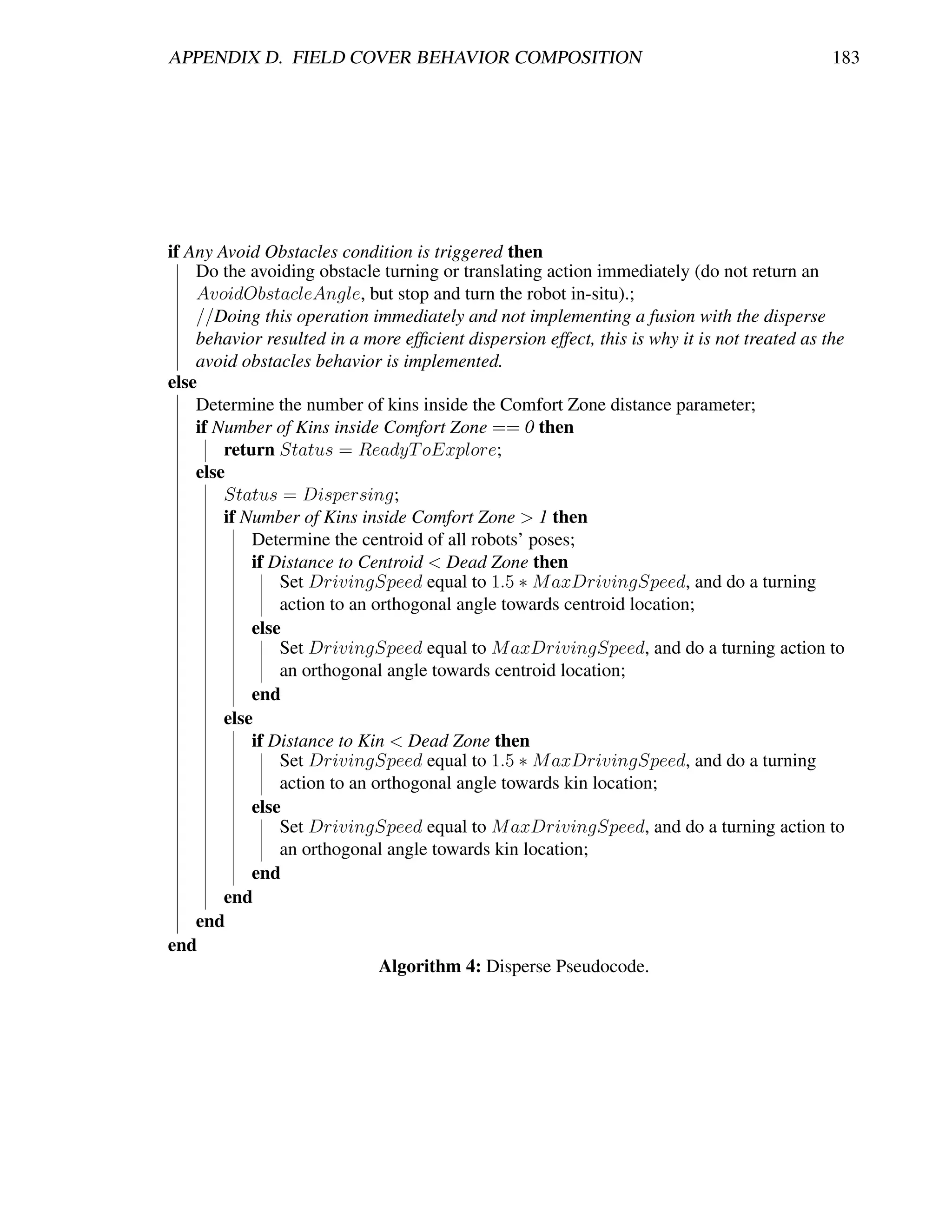
![APPENDIX D. FIELD COVER BEHAVIOR COMPOSITION 184
state, we observed that immediately stopping and turning towards the AvoidObstacleAngle (or
translating to safety as the Avoid Obstacles behavior commands), was more efficient in order
to get all robots dispersed, than by returning a desired angle as the behavior is implemented.
Then, once all the robots have been dispersed, the <if m robots dispersed> condition
is triggered so that the new state comes to be the ReadyToExplore. In this state, two main
actions can happen. First, if the wandering rate is triggered, the Locate Open Area behavior is
activated, subsuming any other action out of turning towards the determined best heading if it
is appropriate, or holding the current driving and steering speeds, which means to do/change
nothing (refer to Algorithm 3). Second, if the wandering rate is not triggered, we fuse outputs
from the Avoid Obstacles and Avoid Past behaviors in a weighted summation. This summation
requires for a careful balance between behaviors gains for which the most important is to
establish an appropriate AvoidP astGain < AvoidObstaclesGain relation [21]. In this way,
with this simple 2-state FSA, we ensure that robots are constantly commanded to spread and
explore the environment. Thus, it can be referred that this FSA constitutes the deliberative part
in our algorithm since it decides which behaviors are the best according to a given situation, so
that the combination of this with the behaviors’ outputs lead us into a hybrid solution such as
the presented in [139] with the main difference that we do not calculate any forces, potential
fields, nor have any sequential targets, thus reducing complexity and avoiding typical local
minima problems. Pseudocode referring these operations is presented in Algorithm 5.
Figure D.2: Implemented 2-state Finite State Automata for autonomous exploration.](https://image.slidesharecdn.com/dtc-phd-thesis-finalversion-121215102213-phpapp01/75/PhD-Thesis-Coordination-of-Multiple-Robotic-Agents-for-Disaster-and-Emergency-Response-202-2048.jpg)
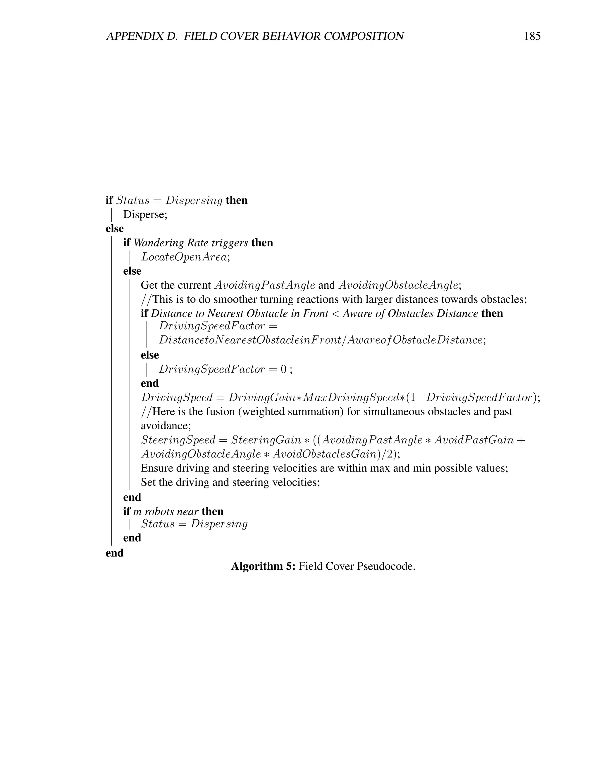
![Bibliography
[1] A BOUAF, J. Trial by fire: teleoperated robot targets chernobyl. Computer Graphics
and Applications, IEEE 18, 4 (jul/aug 1998), 10 –14.
[2] A LAMI , R., C HATILA , R., F LEURY, S., G HALLAB , M., AND I NGRAND , F. An
architecture for autonomy. International Journal of Robotics Research 17 (1998), 315–
337.
[3] A LI , S., AND M ERTSCHING , B. Towards a generic control architecture of rescue
robot systems. In Safety, Security and Rescue Robotics, 2008. SSRR 2008. IEEE Inter-
national Workshop on (oct. 2008), pp. 89 –94.
[4] A LNOUNOU , Y., H AIDAR , M., PAULIK , M., AND A L -H OLOU , N. Service-oriented
architecture: On the suitability for mobile robots. In Electro/Information Technology
(EIT), 2010 IEEE International Conference on (may 2010), pp. 1 –5.
[5] A LTSHULER , Y., YANOVSKI , V., WAGNER , I., AND B RUCKSTEIN , A. Swarm ant
robotics for a dynamic cleaning problem - analytic lower bounds and impossibility
results. In Autonomous Robots and Agents, 2009. ICARA 2009. 4th International Con-
ference on (feb. 2009), pp. 216 –221.
[6] A MIGONI , F. Experimental evaluation of some exploration strategies for mobile
robots. In Robotics and Automation, 2008. ICRA 2008. IEEE International Confer-
ence on (may 2008), pp. 2818 –2823.
[7] A NDERSON , M., AND PAPANIKOLOPOULOS , N. Implicit cooperation strategies for
multi-robot search of unknown areas. Journal of Intelligent Robotics Systems 53 (De-
cember 2008), 381–397.
[8] A NDRILUKA , M., F RIEDMANN , M., KOHLBRECHER , S., M EYER , J., P ETERSEN ,
K., R EINL , C., S CHAUSS , P., S CHNITZPAN , P., S TROBEL , A., T HOMAS , D., AND
VON S TRYK , O. Robocuprescue 2009 - robot league team: Darmstadt rescue robot
team (germany), 2009. Institut f¨ r Flugsysteme und Regelungstechnik.
u
[9] A NGERMANN , M., K HIDER , M., AND ROBERTSON , P. Towards operational sys-
tems for continuous navigation of rescue teams. In Position, Location and Navigation
Symposium, 2008 IEEE/ION (may 2008), pp. 153 –158.
186](https://image.slidesharecdn.com/dtc-phd-thesis-finalversion-121215102213-phpapp01/75/PhD-Thesis-Coordination-of-Multiple-Robotic-Agents-for-Disaster-and-Emergency-Response-204-2048.jpg)
![BIBLIOGRAPHY 187
[10] A RKIN , R., AND D IAZ , J. Line-of-sight constrained exploration for reactive multia-
gent robotic teams. In Advanced Motion Control, 2002. 7th International Workshop on
(2002), pp. 455 – 461.
[11] A RKIN , R. C. Behavior-Based Robotics. The MIT Press, 1998.
[12] A RKIN , R. C., AND BALCH , T. Aura: Principles and practice in review. Journal of
Experimental and Theoretical Artificial Intelligence 9 (1997), 175–189.
[13] A RRICHIELLO , F., H EIDARSSON , H., C HIAVERINI , S., AND S UKHATME , G. S. Co-
operative caging using autonomous aquatic surface vehicles. In Robotics and Automa-
tion (ICRA), 2010 IEEE International Conference on (may 2010), pp. 4763 –4769.
[14] A SAMA , H., H ADA , Y., K AWABATA , K., N ODA , I., TAKIZAWA , O., M EGURO , J.,
I SHIKAWA , K., H ASHIZUME , T., O HGA , T., TAKITA , K., H ATAYAMA , M., M AT-
SUNO , F., AND TADOKORO , S. Rescue Robotics. DDT Project on Robots and Systems
for Urban Search and Rescue. Springer, March 2009, ch. 4. Information Infrastructure
for Rescue System, pp. 57–70.
[15] AURENHAMMER , F., AND K LEIN , R. Handbook of Computational Geometry Auren-
hammer, F. and Klein, R. ”Voronoi Diagrams.” Ch. 5 in Handbook of Computational
Geometry (Ed. J.-R. Sack and J. Urrutia). Amsterdam, Netherlands: North-Holland,
pp. 201-290, 2000. Elsevier Science B. V., 2000, ch. 5. Voronoi Diagrams, pp. 201–
290.
[16] BADANO , B. M. I. A Multi-Agent Architecture with Distributed Coordination for an
Autonomous Robot. PhD thesis, Universitat de Girona, 2008.
[17] BALAGUER , B., BALAKIRSKY, S., C ARPIN , S., L EWIS , M., AND S CRAPPER , C.
Usarsim: a validated simulator for research in robotics and automation. In IEEE/RSJ
IROS (2008).
[18] BALAKIRSKY, S. Usarsim: Providing a framework for multi-robot performance eval-
uation. In In: Proceedings of PerMIS (2006), pp. 98–102.
[19] BALAKIRSKY, S., C ARPIN , S., K LEINER , A., L EWIS , M., V ISSER , A., WANG ,
J., AND Z IPARO , V. A. Towards heterogeneous robot teams for disaster mitigation:
Results and performance metrics from robocup rescue. Journal of Field Robotics 24,
11-12 (2007), 943–967.
[20] BALAKIRSKY, S., C ARPIN , S., AND L EWIS , M. Robots, games, and research: success
stories in usarsim. In Proceedings of the 2009 IEEE/RSJ international conference on
Intelligent robots and systems (Piscataway, NJ, USA, 2009), IROS’09, IEEE Press,
pp. 1–1.
[21] BALCH , T. Avoiding the past: a simple but effective strategy for reactive navigation.
In Robotics and Automation, 1993. Proceedings., 1993 IEEE International Conference
on (may 1993), vol. vol.1, pp. 678 –685.](https://image.slidesharecdn.com/dtc-phd-thesis-finalversion-121215102213-phpapp01/75/PhD-Thesis-Coordination-of-Multiple-Robotic-Agents-for-Disaster-and-Emergency-Response-205-2048.jpg)
![BIBLIOGRAPHY 188
[22] BALCH , T. The impact of diversity on performance in multi-robot foraging. In In Proc.
Autonomous Agents 99 (1999), ACM Press, pp. 92–99.
[23] BALCH , T., AND A RKIN , R. Behavior-based formation control for multirobot teams.
Robotics and Automation, IEEE Transactions on 14, 6 (dec 1998), 926 –939.
[24] BALCH , T., AND H YBINETTE , M. Social potentials for scalable multi-robot forma-
tions. In Robotics and Automation, 2000. Proceedings. ICRA ’00. IEEE International
Conference on (2000), vol. 1, pp. 73 –80 vol.1.
[25] BASILICO , N., AND A MIGONI , F. Defining effective exploration strategies for search
and rescue applications with multi-criteria decision making. In Robotics and Automa-
tion (ICRA), 2011 IEEE International Conference on (may 2011), pp. 4260 –4265.
[26] BAY, H., E SS , A., T UYTELAARS , T., AND VAN G OOL , L. Speeded-up robust features
(surf). Comput. Vis. Image Underst. 110, 3 (June 2008), 346–359.
[27] B EARD , R., M C L AIN , T., G OODRICH , M., AND A NDERSON , E. Coordinated target
assignment and intercept for unmanned air vehicles. Robotics and Automation, IEEE
Transactions on 18, 6 (dec 2002), 911 – 922.
[28] B ECKERS , R., H OLL , O. E., AND D ENEUBOURG , J. L. From local actions to global
tasks: Stigmergy and collective robotics. In Proc. 14th Int. Workshop Synth. Simul.
Living Syst. (1994), R. Brooks and P. Maes, Eds., MIT Press, pp. 181–189.
[29] B EKEY, G. A. Autonomous Robots: From Biological Inspiration to Implementation
and Control. The MIT Press, 2005.
[30] B ENI , G. The concept of cellular robotic system. In Intelligent Control, 1988. Pro-
ceedings., IEEE International Symposium on (aug 1988), pp. 57 –62.
[31] B ERHAULT, M., H UANG , H., K ESKINOCAK , P., KOENIG , S., E LMAGHRABY, W.,
G RIFFIN , P., AND K LEYWEGT, A. Robot exploration with combinatorial auctions.
In Intelligent Robots and Systems, 2003. (IROS 2003). Proceedings. 2003 IEEE/RSJ
International Conference on (oct. 2003), vol. 2, pp. 1957 – 1962 vol.2.
[32] B ETHEL , C., AND M URPHY, R. R. Survey of non-facial/non-verbal affective ex-
pressions for appearance-constrained robots. Systems, Man, and Cybernetics, Part C:
Applications and Reviews, IEEE Transactions on 38, 1 (jan. 2008), 83 –92.
[33] B IRK , A., AND C ARPIN , S. Rescue robotics - a crucial milestone on the road to
autonomous systems. Advanced Robotics Journal 20, 5 (2006), 595–605.
[34] B IRK , A., AND K ENN , H. A control architecture for a rescue robot ensuring safe semi-
autonomous operation. In RoboCup-02: Robot Soccer World Cup VI, G. Kaminka,
P. Lima, and R. Rojas, Eds., LNAI. Springer, 2002.](https://image.slidesharecdn.com/dtc-phd-thesis-finalversion-121215102213-phpapp01/75/PhD-Thesis-Coordination-of-Multiple-Robotic-Agents-for-Disaster-and-Emergency-Response-206-2048.jpg)
![BIBLIOGRAPHY 189
[35] B IRK , A., AND P FINGSTHORN , M. A hmi supporting adjustable autonomy of rescue
robots. In RoboCup 2005: Robot WorldCup IX, I. Noda, A. Jacoff, A. Bredenfeld,
and Y. Takahashi, Eds., vol. 4020 of Lecture Notes in Artificial Intelligence (LNAI).
Springer, 2006, pp. 255 – 266.
[36] B IRK , A., S CHWERTFEGER , S., AND PATHAK , K. A networking framework for
teleoperation in safety, security, and rescue robotics. Wireless Communications, IEEE
16, 1 (february 2009), 6 –13.
[37] B LITCH , J. G. Artificial intelligence technologies for robot assisted urban search and
rescue. Expert Systems with Applications 11, 2 (1996), 109 – 124. Army Applications
of Artificial Intelligence.
[38] B OHN , H., B OBEK , A., AND G OLATOWSKI , F. Sirena - service infrastructure for
real-time embedded networked devices: A service oriented framework for different
domains. In In International Conference on Networking (ICN) (2006).
[39] B OONPINON , N., AND S UDSANG , A. Constrained coverage for heterogeneous multi-
robot team. In Robotics and Biomimetics, 2007. ROBIO 2007. IEEE International
Conference on (dec. 2007), pp. 799 –804.
[40] B ORENSTEIN , J., AND B ORRELL , A. The omnitread ot-4 serpentine robot. In Robotics
and Automation, 2008. ICRA 2008. IEEE International Conference on (may 2008),
pp. 1766 –1767.
[41] B ORENSTEIN , J., AND KOREN , Y. The vector field histogram-fast obstacle avoidance
for mobile robots. Robotics and Automation, IEEE Transactions on 7, 3 (jun 1991),
278 –288.
[42] B OTELHO , S. C., AND A LAMI , R. A multi-robot cooperative task achievement sys-
tem. In Robotics and Automation, 2000. Proceedings. ICRA ’00. IEEE International
Conference on (2000), vol. 3, pp. 2716 –2721 vol.3.
[43] B OURGAULT, F., M AKARENKO , A., W ILLIAMS , S., G ROCHOLSKY, B., AND
D URRANT-W HYTE , H. Information based adaptive robotic exploration. In Intelli-
gent Robots and Systems, 2002. IEEE/RSJ International Conference on (2002), vol. 1,
pp. 540 – 545 vol.1.
[44] B OWEN , D., AND M AC K ENZIE , S. Autonomous collaborative unmanned vehicles:
Technological drivers and constraints. Tech. rep., Defence Research and Development
Canada, 2003.
[45] B RADSKI , G. The OpenCV Library. Dr. Dobb’s Journal of Software Tools (2000).
[46] B REIVOLD , H., AND L ARSSON , M. Component-based and service-oriented software
engineering: Key concepts and principles. In Software Engineering and Advanced
Applications, 2007. 33rd EUROMICRO Conference on (aug. 2007), pp. 13 –20.](https://image.slidesharecdn.com/dtc-phd-thesis-finalversion-121215102213-phpapp01/75/PhD-Thesis-Coordination-of-Multiple-Robotic-Agents-for-Disaster-and-Emergency-Response-207-2048.jpg)
![BIBLIOGRAPHY 190
[47] B ROOKS , A., K AUPP, T., M AKARENKO , A., W ILLIAMS , S., AND O REBACK , A. To-
wards component-based robotics. In Intelligent Robots and Systems (IROS ). IEEE/RSJ
International Conference on (aug. 2005), pp. 163 – 168.
[48] B ROOKS , A., K AUPP, T., M AKARENKO , A., W ILLIAMS , S., AND O REB ACK , A.¨
Orca: A component model and repository. In Software Engineering for Experimental
Robotics, D. Brugali, Ed., vol. 30 of Springer Tracts in Advanced Robotics. Springer -
Verlag, Berlin / Heidelberg, April 2007.
[49] B ROOKS , R. A robust layered control system for a mobile robot. Robotics and Au-
tomation, IEEE Journal of 2, 1 (mar 1986), 14 – 23.
[50] B ROOKS , R. Intelligence without representation. MIT Artificial Intelligence Report 47
(1987), 1–12.
[51] B ROOKS , R. A robot that walks; emergent behaviors from a carefully evolved network.
In Robotics and Automation, 1989. Proceedings., 1989 IEEE International Conference
on (may 1989), vol. vol. 2, pp. 692 –698.
[52] B ROOKS , R. Elephants don’t play chess. Robotics and Autonomous Systems 6, 1-2
(1990), 3– 15.
[53] B ROOKS , R. Intelligence without reason. In COMPUTERS AND THOUGHT, IJCAI-
91 (1991), Morgan Kaufmann, pp. 569–595.
[54] B ROOKS , R., AND F LYNN , A. M. Fast, cheap and out of control: A robot invasion of
the solar system. The British Interplanetary Society 42, 10 (1989), 478–485.
[55] B RUGALI , D., Ed. Software Engineering for Experimental Robotics, vol. 30 of
Springer Tracts in Advanced Robotics. Springer - Verlag, Berlin / Heidelberg, April
2007.
[56] B UI , T., AND TAN , A. A template-based methodology for large-scale ha/dr involving
ephemeral groups - a workflow perspective. In System Sciences, 2007. HICSS 2007.
40th Annual Hawaii International Conference on (jan. 2007), p. 34.
[57] B URGARD , W., M OORS , M., F OX , D., S IMMONS , R., AND T HRUN , S. Collaborative
multi-robot exploration. In Robotics and Automation, 2000. Proceedings. ICRA ’00.
IEEE International Conference on (2000), vol. 1, pp. 476 –481 vol.1.
[58] B URGARD , W., M OORS , M., S TACHNISS , C., AND S CHNEIDER , F. Coordinated
multi-robot exploration. Robotics, IEEE Transactions on 21, 3 (june 2005), 376 – 386.
[59] B UTLER , Z., R IZZI , A., AND H OLLIS , R. Cooperative coverage of rectilinear environ-
ments. In Robotics and Automation, 2000. Proceedings. ICRA ’00. IEEE International
Conference on (2000), vol. 3, pp. 2722 –2727 vol.3.
[60] C ALISI , D., FARINELLI , A., I OCCHI , L., AND NARDI , D. Multi-objective exploration
and search for autonomous rescue robots. J. Field Robotics 24, 8-9 (2007), 763–777.](https://image.slidesharecdn.com/dtc-phd-thesis-finalversion-121215102213-phpapp01/75/PhD-Thesis-Coordination-of-Multiple-Robotic-Agents-for-Disaster-and-Emergency-Response-208-2048.jpg)
![BIBLIOGRAPHY 191
[61] C ALISI , D., NARDI , D., O HNO , K., AND TADOKORO , S. A semi-autonomous tracked
robot system for rescue missions. In SICE Annual Conference, 2008 (aug. 2008),
pp. 2066 –2069.
[62] C ALOUD , P., C HOI , W., L ATOMBE , J. C., L E PAPE , C., AND Y IM , M. Indoor
automation with many mobile robots. In Intelligent Robots and Systems ’90. ’Towards
a New Frontier of Applications’, Proceedings. IROS ’90. IEEE International Workshop
on (jul 1990), pp. 67 –72 vol.1.
[63] C AO , Y. U., F UKUNAGA , A. S., AND K AHNG , A. Cooperative mobile robotics:
Antecedents and directions. Autonomous Robots 4 (1997), 7–27.
[64] C AO , Z., TAN , M., L I , L., G U , N., AND WANG , S. Cooperative hunting by dis-
tributed mobile robots based on local interaction. Robotics, IEEE Transactions on 22,
2 (april 2006), 402 – 406.
[65] C ARLSON , J., AND M URPHY, R. R. How ugvs physically fail in the field. Robotics,
IEEE Transactions on 21, 3 (june 2005), 423 – 437.
[66] C ARPIN , S., AND B IRK , A. Stochastic map merging in noisy rescue environments. In
RoboCup 2004: Robot Soccer World Cup VIII, D. Nardi, M. Riedmiller, and C. Sam-
mut, Eds., vol. 3276 of Lecture Notes in Artificial Intelligence (LNAI). Springer, 2005,
p. p.483ff.
[67] C ARPIN , S., WANG , J., L EWIS , M., B IRK , A., AND JACOFF , A. High fidelity tools
for rescue robotics: Results and perspectives. In RoboCup (2005), A. Bredenfeld,
A. Jacoff, I. Noda, and Y. Takahashi, Eds., vol. 4020 of Lecture Notes in Computer
Science, Springer, pp. 301–311.
[68] C ASPER , J., AND M URPHY, R. R. Human-robot interactions during the robot-assisted
urban search and rescue response at the world trade center. Systems, Man, and Cyber-
netics, Part B: Cybernetics, IEEE Transactions on 33, 3 (june 2003), 367 – 385.
[69] C ASPER , J. L., M ICIRE , M., AND M URPHY, R. R. Issues in intelligent robots for
search and rescue. In Society of Photo-Optical Instrumentation Engineers (SPIE) Con-
ference Series (jul 2000), . C. M. S. G. R. Gerhart, R. W. Gunderson, Ed., vol. 4024 of
Presented at the Society of Photo-Optical Instrumentation Engineers (SPIE) Confer-
ence, pp. 292–302.
[70] C EPEDA , J. S., C HAIMOWICZ , L., AND S OTO , R. Exploring microsoft robotics studio
as a mechanism for service-oriented robotics. Latin American Robotics Symposium and
Intelligent Robotics Meeting 0 (2010), 7–12.
[71] C EPEDA , J. S., C HAIMOWICZ , L., S OTO , R., G ORDILLO , J., A LAN´S -R EYES , E.,
I
AND C ARRILLO -A RCE , L. C. A behavior-based strategy for single and multi-robot au-
tonomous exploration. Sensors Special Issue: New Trends towards Automatic Vehicle
Control and Perception Systems (2012), 12772–12797.](https://image.slidesharecdn.com/dtc-phd-thesis-finalversion-121215102213-phpapp01/75/PhD-Thesis-Coordination-of-Multiple-Robotic-Agents-for-Disaster-and-Emergency-Response-209-2048.jpg)
![BIBLIOGRAPHY 192
[72] C EPEDA , J. S., S OTO , R., G ORDILLO , J., AND C HAIMOWICZ , L. Towards a service-
oriented architecture for teams of heterogeneous autonomous robots. In Artificial In-
telligence (MICAI), 2011 10th Mexican International Conference on (26 2011-dec. 4
2011), pp. 102 –108.
[73] C ESETTI , A., S COTTI , C. P., D I B UO , G., AND L ONGHI , S. A service oriented
architecture supporting an autonomous mobile robot for industrial applications. In
Control Automation (MED), 8th Mediterranean Conference on (june 2010), pp. 604
–609.
[74] C HAIMOWICZ , L. Dynamic Coordination of Cooperative Robots: A Hybrid Systems
Approach. PhD thesis, Universidade Federal de Minas Gerais, 2002.
[75] C HAIMOWICZ , L., C AMPOS , M., AND K UMAR , V. Dynamic role assignment for
cooperative robots. In Robotics and Automation, 2002. Proceedings. ICRA ’02. IEEE
International Conference on (2002), vol. vol.1, pp. 293 – 298.
[76] C HAIMOWICZ , L., C OWLEY, A., G ROCHOLSKY, B., AND J. F. K ELLER , M. A. H.,
K UMAR , V., AND TAYLOR , C. J. Deploying air-ground multi-robot teams in urban
environments. In Proceedings of the Third Multi-Robot Systems Workshop (Washington
D. C., March 2005).
[77] C HAIMOWICZ , L., C OWLEY, A., S ABELLA , V., AND TAYLOR , C. J. Roci: a dis-
tributed framework for multi-robot perception and control. In Intelligent Robots and
Systems, 2003. (IROS 2003). Proceedings. 2003 IEEE/RSJ International Conference
on (oct. 2003), vol. vol.1, pp. 266 – 271.
[78] C HAIMOWICZ , L., K UMAR , V., AND C AMPOS , M. F. M. A paradigm for dynamic
coordination of multiple robots. Autonomous Robots 17 (2004), 7–21.
[79] C HAIMOWICZ , L., M ICHAEL , N., AND K UMAR , V. Controlling swarms of robots
using interpolated implicit functions. In Robotics and Automation, 2005. ICRA 2005.
Proceedings of the 2005 IEEE International Conference on (april 2005), pp. 2487 –
2492.
[80] C HANG , C., AND M URPHY, R. R. Towards robot-assisted mass-casualty triage. In
Networking, Sensing and Control, 2007 IEEE International Conference on (april 2007),
pp. 267 –272.
[81] C HEEMA , U. Expert systems for earthquake damage assessment. Aerospace and Elec-
tronic Systems Magazine, IEEE 22, 9 (sept. 2007), 6 –10.
[82] C HEN , Y., AND BAI , X. On robotics applications in service-oriented architecture.
In Distributed Computing Systems Workshops, 2008. ICDCS ’08. 28th International
Conference on (june 2008), pp. 551 –556.
[83] C HIA , E. S. Engineering disaster relief. Technology and Society Magazine, IEEE 26,
3 (fall 2007), 24 –29.](https://image.slidesharecdn.com/dtc-phd-thesis-finalversion-121215102213-phpapp01/75/PhD-Thesis-Coordination-of-Multiple-Robotic-Agents-for-Disaster-and-Emergency-Response-210-2048.jpg)
![BIBLIOGRAPHY 193
[84] C HOMPUSRI , Y., K HUEANSUWONG , P., D UANGKAW, A., P HOTSATHIAN , T., J UN -
LEE , S., NAMVONG , N., AND S UTHAKORN , J. Robocuprescue 2006 - robot league
team: Independent (thailand), 2006.
[85] C HONNAPARAMUTT, W., AND B IRK , A. A new mechatronic component for adjusting
the footprint of tracked rescue robots. In RoboCup 2006: Robot Soccer World Cup X,
G. Lakemeyer, E. Sklar, D. Sorrenti, and T. Takahashi, Eds., vol. 4434 of Lecture Notes
in Computer Science. Springer Berlin / Heidelberg, 2007, pp. 450–457.
[86] C HOSET, H. Coverage for robotics a survey of recent results. Annals of Mathematics
and Artificial Intelligence 31, 1-4 (May 2001), 113–126.
[87] C HUENGSATIANSUP, K., S AJJAPONGSE , K., K RUAPRADITSIRI , P., C HANMA , C.,
T ERMTHANASOMBAT, N., S UTTASUPA , Y., S ATTARATNAMAI , S., P ONGKAEW,
E., U DSATID , P., H ATTHA , B., W IBULPOLPRASERT, P., U SAPHAPANUS ,
P., T ULYANON , N., W ONGSAISUWAN , M., WANNASUPHOPRASIT, W., AND
C HONGSTITVATANA , P. Plasma-rx: Autonomous rescue robots. In Robotics and
Biomimetics, 2008. ROBIO 2008. IEEE International Conference on (feb. 2009),
pp. 1986–1990.
[88] C LARK , J., AND F IERRO , R. Cooperative hybrid control of robotic sensors for perime-
ter detection and tracking. In American Control Conference, 2005. Proceedings of the
2005 (june 2005), pp. 3500 – 3505 vol. 5.
[89] C ORRELL , N., AND M ARTINOLI , A. Robust distributed coverage using a swarm of
miniature robots. In Robotics and Automation, 2007 IEEE International Conference
on (april 2007), pp. 379 –384.
[90] DALAL , N., AND T RIGGS , W. Histograms of oriented gradients for human detection.
2005 IEEE Computer Society Conference on Computer Vision and Pattern Recognition
CVPR05 1, 3 (2004), 886–893.
[91] DAVIDS , A. Urban search and rescue robots: from tragedy to technology. Intelligent
Systems, IEEE 17, 2 (march-april 2002), 81 –83.
[92] DE H OOG , J., C AMERON , S., AND V ISSER , A. Role-based autonomous multi-robot
exploration. In Future Computing, Service Computation, Cognitive, Adaptive, Con-
tent, Patterns, 2009. COMPUTATIONWORLD ’09. Computation World: (nov. 2009),
pp. 482 –487.
[93] D IAS , M., Z LOT, R., K ALRA , N., AND S TENTZ , A. Market-based multirobot co-
ordination: A survey and analysis. Proceedings of the IEEE 94, 7 (july 2006), 1257
–1270.
[94] D ISSANAYAKE , M., N EWMAN , P., C LARK , S., D URRANT-W HYTE , H., AND
C SORBA , M. A solution to the simultaneous localization and map building (slam)
problem. Robotics and Automation, IEEE Transactions on 17, 3 (jun 2001), 229 –241.](https://image.slidesharecdn.com/dtc-phd-thesis-finalversion-121215102213-phpapp01/75/PhD-Thesis-Coordination-of-Multiple-Robotic-Agents-for-Disaster-and-Emergency-Response-211-2048.jpg)
![BIBLIOGRAPHY 194
[95] D UDEK , G., J ENKIN , M. R. M., M ILIOS , E., AND W ILKES , D. A taxonomy for
multi-agent robotics. Autonomous Robots 3, 4 (1996), 375–397.
[96] E MGU CV. Emgu cv, a cross platform .net wrapper to the opencv image processing
library [online]: http://www.emgu.com/, 2012.
[97] E REMEEV, D. Library avm sdk simple.net [online]: http://edv-
detail.narod.ru/library avm sdk simple net.html, 2012.
[98] E RMAN , A., H OESEL , L., H AVINGA , P., AND W U , J. Enabling mobility in hetero-
geneous wireless sensor networks cooperating with uavs for mission- critical manage-
ment. Wireless Communications, IEEE 15, 6 (december 2008), 38 –46.
[99] FARINELLI , A., I OCCHI , L., AND NARDI , D. Multirobot systems: a classification
focused on coordination. Systems, Man, and Cybernetics, Part B: Cybernetics, IEEE
Transactions on 34, 5 (oct. 2004), 2015 –2028.
[100] F LOCCHINI , P., K ELLETT, M., M ASON , P., AND S ANTORO , N. Map construc-
tion and exploration by mobile agents scattered in a dangerous network. In Parallel
Distributed Processing, 2009. IPDPS 2009. IEEE International Symposium on (may
2009), pp. 1 –10.
[101] F OX , D., KO , J., KONOLIGE , K., L IMKETKAI , B., S CHULZ , D., AND S TEWART, B.
Distributed multirobot exploration and mapping. Proceedings of the IEEE 94, 7 (july
2006), 1325 –1339.
[102] F UKUDA , T., AND I RITANI , G. Evolutional and self-organizing robots-artificial life in
robotics. In Emerging Technologies and Factory Automation, 1994. ETFA ’94., IEEE
Symposium on (nov 1994), pp. 10 –19.
[103] F URGALE , P., AND BARFOOT, T. Visual path following on a manifold in unstructured
three-dimensional terrain. In Robotics and Automation (ICRA), 2010 IEEE Interna-
tional Conference on (may 2010), pp. 534 –539.
[104] G AGE , D. W. Sensor abstractions to support many-robot systems. In Proceedings of
SPIE Mobile Robots VII (1992), pp. 235–246.
[105] G AGE , D. W. Randomized search strategies with imperfect sensors. In In Proceedings
of SPIE Mobile Robots VIII (1993), pp. 270–279.
[106] G ALLUZZO , T., AND K ENT, D. The joint architecture for unmanned systems (jaus)
[online]: http://www.openjaus.com, 2012.
[107] G ARAGE , W. Ros framework [online]: http://www.ros.org/, 2012.
[108] G ARCIA , R. D., VALAVANIS , K. P., AND KONTITSIS , M. A multiplatform on-board
processing system for miniature unmanned vehicles. In ICRA (2006), pp. 2156–2163.
[109] G AZI , V. Swarm aggregations using artificial potentials and sliding-mode control.
Robotics, IEEE Transactions on 21, 6 (dec. 2005), 1208 – 1214.](https://image.slidesharecdn.com/dtc-phd-thesis-finalversion-121215102213-phpapp01/75/PhD-Thesis-Coordination-of-Multiple-Robotic-Agents-for-Disaster-and-Emergency-Response-212-2048.jpg)
![BIBLIOGRAPHY 195
[110] G ERKEY, B. P. A formal analysis and taxonomy of task allocation in multi-robot
systems. The International Journal of Robotics Research 23, 9 (2004), 939–954.
´
[111] G ERKEY, B. P., AND M ATARI C , M. J. Murdoch: Publish/Subscribe Task Allocation
for Heterogeneous Agents. ACM Press, 2000, pp. 203–204.
´
[112] G ERKEY, B. P., AND M ATARI C , M. J. Sold!: auction methods for multirobot co-
ordination. Robotics and Automation, IEEE Transactions on 18, 5 (oct 2002), 758 –
768.
[113] G ERKEY, B. P., VAUGHAN , R. T., S TØY, K., H OWARD , A., S UKHATME , G. S., AND
´
M ATARI C , M. J. Most valuable player: A robot device server for distributed control. In
Proceeding of the IEEE/RSJ International Conference on Intelligent Robotic Systems
(IROS) (Wailea, Hawaii, November 2001), IEEE.
[114] G IFFORD , C., W EBB , R., B LEY, J., L EUNG , D., C ALNON , M., M AKAREWICZ ,
J., BANZ , B., AND AGAH , A. Low-cost multi-robot exploration and mapping. In
Technologies for Practical Robot Applications, 2008. TePRA 2008. IEEE International
Conference on (nov. 2008), pp. 74 –79.
´ ˜
[115] G ONZ ALEZ -BA NOS , H. H., AND L ATOMBE , J.-C. Navigation strategies for exploring
indoor environments. I. J. Robotic Res. 21, 10-11 (2002), 829–848.
[116] G OSSOW, D., P ELLENZ , J., AND PAULUS , D. Danger sign detection using color
histograms and surf matching. In Safety, Security and Rescue Robotics, 2008. SSRR
2008. IEEE International Workshop on (oct. 2008), pp. 13 –18.
[117] G RABOWSKI , R., NAVARRO -S ERMENT, L., PAREDIS , C., AND K HOSLA , P. Hetero-
geneous teams of modular robots for mapping and exploration. Autonomous Robots -
Special Issue on Heterogeneous Multirobot Systems 8 (3) (1999), 271298.
[118] G RANT, L. L., AND V ENAYAGAMOORTHY, G. K. Swarm Intelligence for Collective
Robotic Search. No. 177. Springer, 2009, p. 29.
[119] G ROCHOLSKY, B., BAYRAKTAR , S., K UMAR , V., TAYLOR , C. J., AND PAPPAS , G.
Synergies in feature localization by air-ground robot teams. In in Proc. 9th Int. Symp.
Experimental Robotics (ISER04 (2004), pp. 353–362.
[120] G ROCHOLSKY, B., S WAMINATHAN , R., K ELLER , J., K UMAR , V., AND PAPPAS , G.
Information driven coordinated air-ground proactive sensing. In Robotics and Automa-
tion, 2005. ICRA 2005. Proceedings of the 2005 IEEE International Conference on
(april 2005), pp. 2211 – 2216.
[121] G UARNIERI , M., K URAZUME , R., M ASUDA , H., I NOH , T., TAKITA , K., D EBEN -
EST, P., H ODOSHIMA , R., F UKUSHIMA , E., AND H IROSE , S. Helios system: A team
of tracked robots for special urban search and rescue operations. In Intelligent Robots
and Systems, 2009. IROS 2009. IEEE/RSJ International Conference on (oct. 2009),
pp. 2795 –2800.](https://image.slidesharecdn.com/dtc-phd-thesis-finalversion-121215102213-phpapp01/75/PhD-Thesis-Coordination-of-Multiple-Robotic-Agents-for-Disaster-and-Emergency-Response-213-2048.jpg)
![BIBLIOGRAPHY 196
[122] G UIZZO , E. Robots with their heads in the clouds. Spectrum, IEEE 48, 3 (march
2011), 16 –18.
[123] H ATAZAKI , K., KONYO , M., I SAKI , K., TADOKORO , S., AND TAKEMURA , F. Ac-
tive scope camera for urban search and rescue. In Intelligent Robots and Systems, 2007.
IROS 2007. IEEE/RSJ International Conference on (29 2007-nov. 2 2007), pp. 2596 –
2602.
[124] H EGER , F., AND S INGH , S. Sliding autonomy for complex coordinated multi-robot
tasks: Analysis & experiments. In Proceedings of Robotics: Science and Systems
(Philadelphia, USA, August 2006).
[125] H ELLOA PPS. Ms robotics helloapps [online]: http://www.helloapps.com/, 2012.
[126] H OLLINGER , G., S INGH , S., AND K EHAGIAS , A. Efficient, guaranteed search with
multi-agent teams. In Proceedings of Robotics: Science and Systems (Seattle, USA,
June 2009).
[127] H OLZ , D., BASILICO , N., A MIGONI , F., AND B EHNKE , S. Evaluating the efficiency
of frontier-based exploration strategies. In Robotics (ISR), 2010 41st International
Symposium on and 2010 6th German Conference on Robotics (ROBOTIK) (june 2010),
pp. 1 –8.
´
[128] H OWARD , A., M ATARI C , M. J., AND S UKHATME , G. S. An incremental self-
deployment algorithm for mobile sensor networks. Auton. Robots 13 (September 2002),
113–126.
´
[129] H OWARD , A., M ATARI C , M. J., AND S UKHATME , G. S. Mobile sensor network
deployment using potential fields: A distributed, scalable solution to the area coverage
problem. In Distributed Autonomous Robotic Systems (2002).
[130] H OWARD , A., PARKER , L. E., AND S UKHATME , G. S. Experiments with a large
heterogeneous mobile robot team: Exploration, mapping, deployment and detection.
The International Journal of Robotics Research 25, 5-6 (2006), 431–447.
[131] H SIEH , M. A., C OWLEY, A., K ELLER , J. F., C HAIMOWICZ , L., G ROCHOLSKY, B.,
K UMAR , V., TAYLOR , C. J., E NDO , Y., A RKIN , R. C., J UNG , B., AND ET AL . Adap-
tive teams of autonomous aerial and ground robots for situational awareness. Journal
of Field Robotics 24, 11-12 (2007), 991–1014.
[132] H SIEH , M. A., C OWLEY, A., K UMAR , V., AND TAYLOR , C. Towards the deployment
of a mobile robot network with end-to-end performance guarantees. In Robotics and
Automation, 2006. ICRA 2006. Proceedings 2006 IEEE International Conference on
(may 2006), pp. 2085 –2090.
[133] H UNG , W.-H., L IU , P., AND K ANG , S.-C. Service-based simulator for security robot.
In Advanced robotics and Its Social Impacts, 2008. ARSO 2008. IEEE Workshop on
(aug. 2008), pp. 1 –3.](https://image.slidesharecdn.com/dtc-phd-thesis-finalversion-121215102213-phpapp01/75/PhD-Thesis-Coordination-of-Multiple-Robotic-Agents-for-Disaster-and-Emergency-Response-214-2048.jpg)
![BIBLIOGRAPHY 197
[134] I NC ., D. R. Dr robot, inc. extend your imagination: Jaguar platform specification
[online]: http://jaguar.drrobot.com/specification.asp, 2012.
[135] JACKSON , J. Microsoft robotics studio: A technical introduction. Robotics Automation
Magazine, IEEE 14, 4 (dec. 2007), 82 –87.
[136] JAYASIRI , A., M ANN , G., AND G OSINE , R. Mobile robot navigation in unknown
environments based on supervisory control of partially-observed fuzzy discrete event
systems. In Advanced Robotics, 2009. ICAR 2009. International Conference on (june
2009), pp. 1 –6.
[137] J OHNS , K., AND TAYLOR , T. Professional Microsoft Robotics Developer Studio. Wi-
ley Publishing, Inc., 2008.
[138] J ONES , J. L. Robot Programming: A Practical Guide to Behavior-Based Robotics.
McGrawHill, 2004.
´ ´
[139] J ULI A , M., R EINOSO , O., G IL , A., BALLESTA , M., AND PAY A , L. A hybrid so-
lution to the multi-robot integrated exploration problem. Engineering Applications of
Artificial Intelligence 23, 4 (2010), 473 – 486.
[140] J UNG , B., AND S., S. G. Tracking targets using multiple robots: The effect of envi-
ronment occlusion. Autonomous Robots 13 (November 2002), 191–205.
[141] K AMEGAWA , T., S AIKAI , K., S UZUKI , S., G OFUKU , A., O OMURA , S., H ORIKIRI ,
T., AND M ATSUNO , F. Development of grouped rescue robot platforms for informa-
tion collection in damaged buildings. In SICE Annual Conference, 2008 (aug. 2008),
pp. 1642 –1647.
[142] K AMEGAWA , T., YAMASAKI , T., I GARASHI , H., AND M ATSUNO , F. Development
of the snake-like rescue robot. In Robotics and Automation, 2004. Proceedings. ICRA
’04. 2004 IEEE International Conference on (april-1 may 2004), vol. 5, pp. 5081 –
5086 Vol.5.
[143] K ANNAN , B., AND PARKER , L. Metrics for quantifying system performance in intel-
ligent, fault-tolerant multi-robot teams. In Intelligent Robots and Systems, 2007. IROS
2007. IEEE/RSJ International Conference on (29 2007-nov. 2 2007), pp. 951 –958.
[144] K ANTOR , G., S INGH , S., P ETERSON , R., RUS , D., DAS , A., K UMAR , V., P EREIRA ,
G., AND S PLETZER , J. Distributed Search and Rescue with Robot and Sensor Teams.
Springer, 2006, p. 529538.
[145] K ENN , H., AND B IRK , A. From games to applications: Component reuse in rescue
robots. In In RoboCup 2004: Robot Soccer World Cup VIII, Lecture Notes in Artificial
Intelligence (LNAI (2005), Springer.
[146] K IM , J., E SPOSITO , J. M., AND K UMAR , V. An rrt-based algorithm for testing
and validating multi-robot controllers. In Robotics: Science and Systems’05 (2005),
pp. 249–256.](https://image.slidesharecdn.com/dtc-phd-thesis-finalversion-121215102213-phpapp01/75/PhD-Thesis-Coordination-of-Multiple-Robotic-Agents-for-Disaster-and-Emergency-Response-215-2048.jpg)
![BIBLIOGRAPHY 198
[147] K IM , S. H., AND J EON , J. W. Programming lego mindstorms nxt with visual program-
ming. In Control, Automation and Systems, 2007. ICCAS ’07. International Conference
on (oct. 2007), pp. 2468 –2472.
[148] KOES , M., N OURBAKHSH , I., AND S YCARA , K. Constraint optimization coordi-
nation architecture for search and rescue robotics. In Robotics and Automation, 2006.
ICRA 2006. Proceedings 2006 IEEE International Conference on (may 2006), pp. 3977
–3982.
[149] KONG , C. S., P ENG , N. A., AND R EKLEITIS , I. Distributed coverage with multi-
robot system. In Robotics and Automation, 2006. ICRA 2006. Proceedings 2006 IEEE
International Conference on (may 2006), pp. 2423 –2429.
[150] K UMAR , V., RUS , D., AND S UKHATME , G. S. Networked Robots. Springer, 2008,
ch. 41. Networked Robots, pp. 943–958.
¨
[151] L ANG , D., H ASELICH , M., P RINZEN , M., BAUSCHKE , S., G EMMEL , A., G IESEN ,
´
J., H AHN , R., H ARAK E , L., R EIMCHE , P., S ONNEN , G., VON S TEIMKER , M.,
T HIERFELDER , S., AND PAULUS , D. Robocuprescue 2011 - robot league team: resko-
at-unikoblenz (germany), 2011.
[152] L ANG , H., WANG , Y., AND DE S ILVA , C. Mobile robot localization and object pose
estimation using optical encoder, vision and laser sensors. In Automation and Logistics,
2008. ICAL 2008. IEEE International Conference on (sept. 2008), pp. 617 –622.
[153] L ATHROP, S., AND KORPELA , C. Towards a distributed, cognitive robotic architecture
for autonomous heterogeneous robotic platforms. In Technologies for Practical Robot
Applications, 2009. TePRA 2009. IEEE International Conference on (nov. 2009), pp. 61
–66.
[154] L AVALLE , S. M. Planning Algorithms. Cambridge University Press, 2006.
[155] L EE , D., AND R ECCE , M. Quantitative evaluation of the exploration strategies of a
mobile robot. Int. J. Rob. Res. 16, 4 (Aug. 1997), 413–447.
[156] L EE , J., AND B UI , T. A template-based methodology for disaster management infor-
mation systems. In System Sciences, 2000. Proceedings of the 33rd Annual Hawaii
International Conference on (jan. 2000), p. 7 pp. vol.2.
[157] L EROUX , C. Microdrones: Micro drone autonomous navigation of environment sens-
ing [online]: http://www.ist-microdrones.org, 2011.
[158] L IU , J., WANG , Y., L I , B., AND M A , S. Current research, key performances and
future development of search and rescue robots. Frontiers of Mechanical Engineering
in China 2 (2007), 404–416.
[159] L IU , J., AND W U , J. Multi-Agent Robotic Systems. CRC Press, 2001.](https://image.slidesharecdn.com/dtc-phd-thesis-finalversion-121215102213-phpapp01/75/PhD-Thesis-Coordination-of-Multiple-Robotic-Agents-for-Disaster-and-Emergency-Response-216-2048.jpg)
![BIBLIOGRAPHY 199
[160] L IU , Z., A NG , M.H., J., AND S EAH , W. Reinforcement learning of cooperative
behaviors for multi-robot tracking of multiple moving targets. In Intelligent Robots
and Systems, 2005. (IROS 2005). 2005 IEEE/RSJ International Conference on (aug.
2005), pp. 1289 – 1294.
[161] L OCHMATTER , T., AND M ARTINOLI , A. Simulation experiments with bio-inspired
algorithms for odor source localization in laminar wind flow. In Machine Learning
and Applications, 2008. ICMLA ’08. Seventh International Conference on (dec. 2008),
pp. 437 –443.
[162] L OCHMATTER , T., RODUIT, P., C IANCI , C., C ORRELL , N., JACOT, J., AND M ARTI -
NOLI , A. Swistrack - a flexible open source tracking software for multi-agent systems.
In Intelligent Robots and Systems, 2008. IROS 2008. IEEE/RSJ International Confer-
ence on (sept. 2008), pp. 4004 –4010.
[163] L OWE , D. G. Distinctive image features from scale- invariant keypoints. International
Journal of Computer Vision 602 (2004), 91–110.
[164] M ANO , H., M IYAZAWA , K., C HATTERJEE , R., AND M ATSUNO , F. Autonomous
generation of behavioral trace maps using rescue robots. In Intelligent Robots and Sys-
tems, 2009. IROS 2009. IEEE/RSJ International Conference on (oct. 2009), pp. 2809
–2814.
[165] M ANYIKA , J., AND D URRANT-W HYTE , H. Data Fusion and Sensor Management:
A Decentralized Information-Theoretic Approach. Prentice Hall PTR, Upper Saddle
River, NJ, USA, 1995.
[166] M ARCOLINO , L., AND C HAIMOWICZ , L. A coordination mechanism for swarm nav-
igation: experiments and analysis. In AAMAS (3) (2008), pp. 1203–1206.
[167] M ARCOLINO , L., AND C HAIMOWICZ , L. No robot left behind: Coordination to over-
come local minima in swarm navigation. In Robotics and Automation, 2008. ICRA
2008. IEEE International Conference on (may 2008), pp. 1904 –1909.
[168] M ARINO , A., PARKER , L. E., A NTONELLI , G., AND C ACCAVALE , F. Behavioral
control for multi-robot perimeter patrol: A finite state automata approach. In Robotics
and Automation, 2009. ICRA ’09. IEEE International Conference on (may 2009),
pp. 831 –836.
[169] M ARJOVI , A., N UNES , J., M ARQUES , L., AND DE A LMEIDA , A. Multi-robot ex-
ploration and fire searching. In Intelligent Robots and Systems, 2009. IROS 2009.
IEEE/RSJ International Conference on (oct. 2009), pp. 1929 –1934.
´
[170] M ATARI C , M. J. Designing emergent behaviors: From local interactions to collective
intelligence. In In In Proceedings of the International Conference on Simulation of
Adaptive Behavior: From Animals to Animats (1992), vol. 2, pp. 432–441.
´
[171] M ATARI C , M. J. Group behavior and group learning. In From Perception to Action
Conference, 1994., Proceedings (sept. 1994), pp. 326 – 329.](https://image.slidesharecdn.com/dtc-phd-thesis-finalversion-121215102213-phpapp01/75/PhD-Thesis-Coordination-of-Multiple-Robotic-Agents-for-Disaster-and-Emergency-Response-217-2048.jpg)
![BIBLIOGRAPHY 200
´
[172] M ATARI C , M. J. Interaction and Intelligent Behavior. PhD thesis, Massachusetts
Institute of Technology, Cambridge, MA, USA, 1994.
´
[173] M ATARI C , M. J. Designing and understanding adaptive group behavior. Adaptive
Behavior 4 (1995), 51–80.
´
[174] M ATARI C , M. J. Issues and approaches in the design of collective autonomous agents.
Robotics and Autonomous Systems 16, 2-4 (1995), 321–331.
´
[175] M ATARI C , M. J. Behavior-based control: Examples from navigation, learning, and
group behavior. Journal of Experimental and Theoretical Artificial Intelligence 9
(1997), 323–336.
´
[176] M ATARI C , M. J. Coordination and learning in multirobot systems. Intelligent Systems
and their Applications, IEEE 13, 2 (mar/apr 1998), 6 –8.
´
[177] M ATARI C , M. J. Situated robotics. In Encyclopedia of Cognitive Science. Nature
Publishing Group, 2002.
´
[178] M ATARI C , M. J., AND M ICHAUD , F. Behavior-Based Systems. Springer, 2008, ch. 38.
Behavior-Based Systems, pp. 891–909.
[179] M ATSUMOTO , A., A SAMA , H., I SHIDA , Y., O ZAKI , K., AND E NDO , I. Communi-
cation in the autonomous and decentralized robot system actress. In Intelligent Robots
and Systems ’90. ’Towards a New Frontier of Applications’, Proceedings. IROS ’90.
IEEE International Workshop on (Jul 1990), vol. vol. 2, pp. 835–840.
[180] M ATSUNO , F., H IROSE , S., A KIYAMA , I., I NOH , T., G UARNIERI , M., S HIROMA ,
N., K AMEGAWA , T., O HNO , K., AND S ATO , N. Introduction of mission unit on
information collection by on-rubble mobile platforms of development of rescue robot
systems (ddt) project in japan. In SICE-ICASE, 2006. International Joint Conference
(oct. 2006), pp. 4186 –4191.
[181] M ATSUNO , F., AND TADOKORO , S. Rescue robots and systems in japan. In Robotics
and Biomimetics, 2004. ROBIO 2004. IEEE International Conference on (aug. 2004),
pp. 12 –20.
[182] M C E NTIRE , D. A. Disaster Response and Recovery. Wiley Publishing, Inc., 2007.
[183] M C L URKIN , J., AND S MITH , J. Distributed algorithms for dispersion in indoor envi-
ronments using a swarm of autonomous mobile robots. In 7th Distributed Autonomous
Robotic Systems (2004).
[184] M ICIRE , M. Analysis of the robotic-assisted search and rescue response to the world
trade center disaster. Master’s thesis, University of South Florida, May 2002.
[185] M ICIRE , M., D ESAI , M., D RURY, J. L., M C C ANN , E., N ORTON , A., T SUI , K. M.,
AND YANCO , H. A. Design and validation of two-handed multi-touch tabletop con-
trollers for robot teleoperation. In IUI (2011), pp. 145–154.](https://image.slidesharecdn.com/dtc-phd-thesis-finalversion-121215102213-phpapp01/75/PhD-Thesis-Coordination-of-Multiple-Robotic-Agents-for-Disaster-and-Emergency-Response-218-2048.jpg)
![BIBLIOGRAPHY 201
[186] M ICIRE , M., AND YANCO , H. Improving disaster response with multi-touch tech-
nologies. In Intelligent Robots and Systems, 2007. IROS 2007. IEEE/RSJ International
Conference on (29 2007-nov. 2 2007), pp. 2567 –2568.
[187] M IHANKHAH , E., A BOOSAEEDAN , E., K ALANTARI , A., S EMSARILAR , H., M OT-
TAGHI , S., A LIZADEHARJMAND , M., F OROUZIDEH , A., S HARH , M. A. M.,
S HAHRYARI , S., AND M OGHADMNEJAD , N. Robocuprescue 2009 - robot league
team: Resquake (iran), 2009.
[188] M INSKY, M. The Emotion Machine: Commonsense Thinking, Artificial Intelligence,
and the Future of the Human Mind. Simon & Schuster, 2006.
[189] M IZUMOTO , H., M ANO , H., KON , K., S ATO , N., K ANAI , R., G OTO , K., S HIN , H.,
I GARASHI , H., AND M ATSUNO , F. Robocuprescue 2009 - robot league team: Shinobi
(japan), 2009.
[190] M OOSAVIAN , S. A. A., K ALANTARI , A., S EMSARILAR , H., A BOOSAEEDAN , E.,
AND M IHANKHAH , E. Resquake: A tele-operative rescue robot. Journal of Mechani-
cal Design 131, 8 (2009), 081005.
[191] M OURIKIS , A., AND ROUMELIOTIS , S. Performance analysis of multirobot coopera-
tive localization. Robotics, IEEE Transactions on 22, 4 (aug. 2006), 666 –681.
[192] M URPHY, R. R. Introduction to AI Robotics. The MIT Press, 2000.
[193] M URPHY, R. R. Human-robot interaction in rescue robotics. Systems, Man, and Cy-
bernetics, Part C: Applications and Reviews, IEEE Transactions on 34, 2 (may 2004),
138 –153.
[194] M URPHY, R. R. Trial by fire. Robotics Automation Magazine, IEEE 11, 3 (sept. 2004),
50 – 61.
[195] M URPHY, R. R., B ROWN , R., G RANT, R., AND A RNETT, C. Preliminary domain
theory for robot-assisted wildland firefighting. In Safety, Security Rescue Robotics
(SSRR), 2009 IEEE International Workshop on (nov. 2009), pp. 1 –6.
[196] M URPHY, R. R., C ASPER , J., H YAMS , J., M ICIRE , M., AND M INTEN , B. Mobility
and sensing demands in usar. In Industrial Electronics Society, 2000. IECON 2000.
26th Annual Conference of the IEEE (2000), vol. 1, pp. 138 –142 vol.1.
[197] M URPHY, R. R., C ASPER , J., AND M ICIRE , M. Potential tasks and research issues
for mobile robots in robocup rescue. In RoboCup 2000: Robot Soccer World Cup IV
(London, UK, 2001), Springer-Verlag, pp. 339–344.
[198] M URPHY, R. R., C ASPER , J., M ICIRE , M., AND H YAMS , J. Assessment of the nist
standard test bed for urban search and rescue, 2000.](https://image.slidesharecdn.com/dtc-phd-thesis-finalversion-121215102213-phpapp01/75/PhD-Thesis-Coordination-of-Multiple-Robotic-Agents-for-Disaster-and-Emergency-Response-219-2048.jpg)
![BIBLIOGRAPHY 202
[199] M URPHY, R. R., C ASPER , J., M ICIRE , M., H YAMS , J., ROBIN , D., M URPHY, R.,
M URPHY, R., M URPHY, R. R., C ASPER , J. L., M ICIRE , M. J., AND H YAMS , J.
Mixed-initiative control of multiple heterogeneous robots for urban search and rescue,
2000.
[200] M URPHY, R. R., K RAVITZ , J., P ELIGREN , K., M ILWARD , J., AND S TANWAY, J.
Preliminary report: Rescue robot at crandall canyon, utah, mine disaster. In Robotics
and Automation, 2008. ICRA 2008. IEEE International Conference on (may 2008),
pp. 2205 –2206.
[201] M URPHY, R. R., K RAVITZ , J., S TOVER , S., AND S HOURESHI , R. Mobile robots in
mine rescue and recovery. Robotics Automation Magazine, IEEE 16, 2 (june 2009), 91
–103.
[202] M URPHY, R. R., L ISETTI , C. L., TARDIF, R., I RISH , L., AND G AGE , A. Emotion-
based control of cooperating heterogeneous mobile robots. Robotics and Automation,
IEEE Transactions on 18, 5 (oct 2002), 744 – 757.
[203] M URPHY, R. R., S TEIMLE , E., H ALL , M., L INDEMUTH , M., T REJO , D.,
H URLEBAUS , S., M EDINA -C ETINA , Z., AND S LOCUM , D. Robot-assisted bridge
inspection after hurricane ike. In Safety, Security Rescue Robotics (SSRR), 2009 IEEE
International Workshop on (nov. 2009), pp. 1 –5.
[204] M URPHY, R. R., TADOKORO , S., NARDI , D., JACOFF , A., F IORINI , P., C HOSET, H.,
AND E RKMEN , A. M. Search and Rescue Robotics. Springer, 2008, ch. 50. Search
and Rescue Robotics, p. 11511173.
[205] NAGATANI , K., O KADA , Y., T OKUNAGA , N., YOSHIDA , K., K IRIBAYASHI , S.,
O HNO , K., TAKEUCHI , E., TADOKORO , S., A KIYAMA , H., N ODA , I., YOSHIDA ,
T., AND KOYANAGI , E. Multi-robot exploration for search and rescue missions: A
report of map building in robocuprescue 2009. In Safety, Security Rescue Robotics
(SSRR), 2009 IEEE International Workshop on (nov. 2009), pp. 1 –6.
[206] NAGHSH , A., G ANCET, J., TANOTO , A., AND ROAST, C. Analysis and design of
human-robot swarm interaction in firefighting. In Robot and Human Interactive Com-
munication, 2008. RO-MAN 2008. The 17th IEEE International Symposium on (aug.
2008), pp. 255 –260.
[207] NATER , F., G RABNER , H., , AND G OOL , L. V. Exploiting simple hierarchies for un-
supervised human behavior analysis. In In Proceedings IEEE Conference on Computer
Vision and Pattern Recognition (CVPR) (June 2010).
[208] NAVARRO , I., P UGH , J., M ARTINOLI , A., AND M ATIA , F. A distributed scalable ap-
proach to formation control in multi-robot systems. In Proceedings of the International
Symposium on Distributed A utonomous Robotic Systems (2008).
[209] N EVATIA , Y., S TOYANOV, T., R ATHNAM , R., P FINGSTHORN , M., M ARKOV, S.,
A MBRUS , R., AND B IRK , A. Augmented autonomy: Improving human-robot team](https://image.slidesharecdn.com/dtc-phd-thesis-finalversion-121215102213-phpapp01/75/PhD-Thesis-Coordination-of-Multiple-Robotic-Agents-for-Disaster-and-Emergency-Response-220-2048.jpg)
![BIBLIOGRAPHY 203
performance in urban search and rescue. In Intelligent Robots and Systems, 2008.
IROS 2008. IEEE/RSJ International Conference on (sept. 2008), pp. 2103 –2108.
[210] N ODA , I., H ADA , Y., ICHI M EGURO , J., AND S HIMORA , H. Rescue Robotics. DDT
Project on Robots and Systems for Urban Search and Rescue. Springer, 2009, ch. 8.
Information Sharing and Integration Framework Among Rescue Robots Information
Systems, pp. 145–160.
[211] N ORDFELTH , A., W ETZIG , C., P ERSSON , M., H AMRIN , P., K UIVINEN , R., FALK ,
P., AND L UNDGREN , B. Robocuprescue 2009 - robot league team: Robocuprescue
team (rrt) uppsala university (sweden), 2009.
[212] N OURBAKHSH , I., S YCARA , K., KOES , M., YONG , M., L EWIS , M., AND B URION ,
S. Human-robot teaming for search and rescue. Pervasive Computing, IEEE 4, 1
(jan.-march 2005), 72 – 79.
[213] OF C OMPANIES , I. G. International submarine engineering ltd. [online]:
http://www.ise.bc.ca/products.html, 2012.
[214] OF S TANDARDS , N. I., AND T ECHNOLOGY. Performance metrics and test arenas for
autonomous mobile robots [online]: http://www.nist.gov/el/isd/testarenas.cfm, 2011.
[215] O HNO , K., M ORIMURA , S., TADOKORO , S., KOYANAGI , E., AND YOSHIDA ,
T. Semi-autonomous control of 6-dof crawler robot having flippers for getting over
unknown-steps. In Intelligent Robots and Systems, 2007. IROS 2007. IEEE/RSJ Inter-
national Conference on (29 2007-nov. 2 2007), pp. 2559 –2560.
[216] O HNO , K., AND YOSHIDA , T. Robocuprescue 2010 - robot league team: Pelican
united (japan), 2010.
[217] O LSON , G. M., S HEPPARD , S. B., AND S OLOWAY, E. Can
japan send in robots to fix troubled nuclear reactors? [online]:
http://spectrum.ieee.org/automaton/robotics/industrial-robots/japan-robots-to-fix-
troubled-nuclear-reactors, 2011. This is an electronic document. Date of publication:
[March 22, 2011]. Date retrieved: June 23, 2011. Date last modified: [Date
unavailable].
[218] O REBACK , A., AND C HRISTENSEN , H. I. Evaluation of architectures for mobile
robotics. Autonomous Robots 14 (2003), 33–49.
[219] PAPAZOGLOU , M., T RAVERSO , P., D USTDAR , S., AND L EYMANN , F. Service-
oriented computing: State of the art and research challenges. Computer 40, 11 (nov.
2007), 38 –45.
[220] PARKER , L. E. Designing control laws for cooperative agent teams. In Robotics and
Automation, 1993. Proceedings., 1993 IEEE International Conference on (may 1993),
pp. 582 –587 vol.3.](https://image.slidesharecdn.com/dtc-phd-thesis-finalversion-121215102213-phpapp01/75/PhD-Thesis-Coordination-of-Multiple-Robotic-Agents-for-Disaster-and-Emergency-Response-221-2048.jpg)
![BIBLIOGRAPHY 204
[221] PARKER , L. E. Alliance: an architecture for fault tolerant multirobot cooperation.
Robotics and Automation, IEEE Transactions on 14, 2 (apr 1998), 220 –240.
[222] PARKER , L. E. Distributed intelligence: Overview of the field and its application in
multi-robot systems. Journal of Physical Agents 2, 1 (2008), 5–14.
[223] PARKER , L. E. Multiple Mobile Robot Systems. Springer, 2008, ch. 40. Multiple
Mobile Robot Systems, pp. 921–942.
[224] PATHAK , K., B IRK , A., S CHWERTFEGER , S., D ELCHEF, I., AND M ARKOV, S. Fully
autonomous operations of a jacobs rugbot in the robocup rescue robot league 2006. In
Safety, Security and Rescue Robotics, 2007. SSRR 2007. IEEE International Workshop
on (sept. 2007), pp. 1 –6.
[225] P FINGSTHORN , M., N EVATIA , Y., S TOYANOV, T., R ATHNAM , R., M ARKOV, S.,
AND B IRK , A. Towards cooperative and decentralized mapping in the jacobs virtual
rescue team. In RoboCup (2008), pp. 225–234.
[226] P IMENTA , L. C. A., S CHWAGER , M., L INDSEY, Q., K UMAR , V., RUS , D.,
M ESQUITA , R. C., AND P EREIRA , G. Simultaneous coverage and tracking (scat)
of moving targets with robot networks. In WAFR (2008), pp. 85–99.
[227] P OOL , R. Fukushima: the facts. Engineering Technology 6, 4 (may 2011), 32 –36.
[228] P RATT, K., M URPHY, R. R., B URKE , J., C RAIGHEAD , J., G RIFFIN , C., AND
S TOVER , S. Use of tethered small unmanned aerial system at berkman plaza ii col-
lapse. In Safety, Security and Rescue Robotics, 2008. SSRR 2008. IEEE International
Workshop on (oct. 2008), pp. 134 –139.
[229] P UGH , J., AND M ARTINOLI , A. Inspiring and modeling multi-robot search with par-
ticle swarm optimization. In Swarm Intelligence Symposium, 2007. SIS 2007. IEEE
(april 2007), pp. 332 –339.
[230] Q UIGLEY, M., C ONLEY, K., G ERKEY, B. P., FAUST, J., F OOTE , T., L EIBS , J.,
W HEELER , R., AND N G , A. Y. Ros: an open-source robot operating system. In
ICRA Workshop on Open Source Software (2009).
[231] R AHMAN , M., M IAH , M., G UEAIEB , W., AND S ADDIK , A. Senora: A p2p service-
oriented framework for collaborative multirobot sensor networks. Sensors Journal,
IEEE 7, 5 (may 2007), 658 –666.
[232] R EKLEITIS , I., D UDEK , G., AND M ILIOS , E. Multi-robot collaboration for robust
exploration. Annals of Mathematics and Artificial Intelligence 31 (2001), 7–40.
[233] R ESEARCH , M. Kinect for windows sdk beta [online]: http://www.microsoft.com/en-
us/kinectforwindows/, 2012.
[234] R ESEARCH , M. Microsoft robotics [online]: http://www.microsoft.com/robotics/,
2012.](https://image.slidesharecdn.com/dtc-phd-thesis-finalversion-121215102213-phpapp01/75/PhD-Thesis-Coordination-of-Multiple-Robotic-Agents-for-Disaster-and-Emergency-Response-222-2048.jpg)
![BIBLIOGRAPHY 205
[235] R EYNOLDS , C. Red 3d, steering behaviors, boids and opensteer [online]:
http://red3d.com/cwr/, 2012.
[236] R EYNOLDS , C. W. Steering behaviors for autonomous characters, vol. San Jose,.
Citeseer, 1999, pp. 763–782.
[237] R ICHARDSON , D. Robots to the rescue? Engineering Technology 6, 4 (may 2011), 52
–54.
[238] ROBO R EALM. Roborealm vision for machines [online]: http://www.roborealm.com/,
2012.
[239] ROOKER , M. N., AND B IRK , A. Combining exploration and ad-hoc networking in
robocup rescue. In RoboCup 2004: Robot Soccer World Cup VIII, D. Nardi, M. Ried-
miller, and C. Sammut, Eds., vol. 3276 of Lecture Notes in Artificial Intelligence
(LNAI). Springer, 2005, pp. pp.236–246.
[240] ROOKER , M. N., AND B IRK , A. Multi-robot exploration under the constraints of
wireless networking. Control Engineering Practice 15, 4 (2007), 435 – 445.
[241] ROY, N., AND D UDEK , G. Collaborative robot exploration and rendezvous: Algo-
rithms, performance bounds and observations. Autonomous Robots 11, 2 (2001), 117–
136.
[242] RYBSKI , P., PAPANIKOLOPOULOS , N., S TOETER , S., K RANTZ , D., Y ESIN , K.,
G INI , M., VOYLES , R., H OUGEN , D., N ELSON , B., AND E RICKSON , M. Enlisting
rangers and scouts for reconnaissance and surveillance. Robotics Automation Maga-
zine, IEEE 7, 4 (dec 2000), 14 –24.
´ ´
[243] S ALL E , D., T RAONMILIN , M., C ANOU , J., AND D UPOURQU E , V. Using microsoft
robotics studio for the design of generic robotics controllers: the robubox software.
In IEEE ICRA 2007 Workshop on Software Development and Integration in Robotics
(SDIR-II) (April 2007), D. Brugali, C. Schlegel, I. A. Nesnas, W. D. Smart, and
A. Braendle, Eds., SDIR-II, IEEE Robotics and Automation Society.
[244] S ANFELIU , A., A NDRADE , J UANAND E MDE , W. R., AND I LA , V. S. Ubiq-
uitous networking robotics in urban settings [online]: http://www.urus.upc.es/ ,
http://www.urus.upc.es/nuevooutcomes.html, 2011.
[245] S ATO , N., M ATSUNO , F., AND S HIROMA , N. Fuma : Platform development and
system integration for rescue missions. In Safety, Security and Rescue Robotics, 2007.
SSRR 2007. IEEE International Workshop on (sept. 2007), pp. 1 –6.
[246] S ATO , N., M ATSUNO , F., YAMASAKI , T., K AMEGAWA , T., S HIROMA , N., AND
I GARASHI , H. Cooperative task execution by a multiple robot team and its operators
in search and rescue operations. In Intelligent Robots and Systems, 2004. (IROS 2004).
Proceedings. 2004 IEEE/RSJ International Conference on (sept.-2 oct. 2004), vol. 2,
pp. 1083 – 1088 vol.2.](https://image.slidesharecdn.com/dtc-phd-thesis-finalversion-121215102213-phpapp01/75/PhD-Thesis-Coordination-of-Multiple-Robotic-Agents-for-Disaster-and-Emergency-Response-223-2048.jpg)
![BIBLIOGRAPHY 206
[247] S CHAFROTH , D., B OUABDALLAH , S., B ERMES , C., AND S IEGWART, R. From the
test benches to the first prototype of the mufly micro helicopter. Journal of Intelligent
Robotic Systems 54 (2009), 245–260.
[248] S CHWAGER , M., M C L URKIN , J., S LOTINE , J.-J. E., AND RUS , D. From theory
to practice: Distributed coverage control experiments with groups of robots. In ISER
(2008), pp. 127–136.
¨
[249] S CHWERTFEGER , S., P OPPINGA , J., PATHAK , K., B ULOW, H., VASKEVICIUS , N.,
AND B IRK , A. Robocuprescue 2009 - robot league team: Jacobs university (germany),
2009.
[250] S COTTI , C. P., C ESETTI , A., DI B UO , G., AND L ONGHI , S. Service oriented real-
time implementation of slam capability for mobile robots, 2010.
[251] S ELLNER , B., H EGER , F., H IATT, L., S IMMONS , R., AND S INGH , S. Coordinated
multiagent teams and sliding autonomy for large-scale assembly. Proceedings of the
IEEE 94, 7 (july 2006), 1425 –1444.
[252] S HAHRI , A. M., N OROUZI , M., K ARAMBAKHSH , A., M ASHAT, A. H., C HEGINI , J.,
M ONTAZERZOHOUR , H., R AHMANI , M., NAMAZIFAR , M. J., A SADI , B., M ASHAT,
M. A., K ARIMI , M., M AHDIKHANI , B., AND A ZIZI , V. Robocuprescue 2010 - robot
league team: Mrl rescue robot (iran), 2010.
[253] S HENG , W., YANG , Q., TAN , J., AND X I , N. Distributed multi-robot coordination in
area exploration. Robotics and Autonomous Systems 54, 12 (2006), 945 – 955.
[254] S IDDHARTHA , H., S ARIKA , R., AND K ARLAPALEM , K. Score vector : A new eval-
uation scheme for robocup rescue simuation competition 2009, 2009.
[255] S IEGWART, R., AND N OURBAKHSH , I. R. Introduction to Autonomous Mobile
Robots. The MIT Press, 2004.
[256] S IMMONS , R., A PFELBAUM , D., B URGARD , W., F OX , D., M OORS , M., AND ET AL .
Coordination for multi-robot exploration and mapping. In In Proceedings of the AAAI
National Conference on Artificial Intelligence (2000), AAAI.
[257] S IMMONS , R., L IN , L. J., AND F EDOR , C. Autonomous task control for mobile
robots. In Intelligent Control, 1990. Proceedings., 5th IEEE International Symposium
on (sep 1990), vol. vol. 2, pp. 663 –668.
[258] S IMMONS , R., S INGH , S., H ERSHBERGER , D., R AMOS , J., AND S MITH , T. First
results in the coordination of heterogeneous robots for large-scale assembly. In Exper-
imental Robotics VII, vol. 271 of Lecture Notes in Control and Information Sciences.
Springer Berlin / Heidelberg, 2001, pp. 323–332.
[259] S TACHNISS , C., M ARTINEZ M OZOS , O., AND B URGARD , W. Efficient exploration
of unknown indoor environments using a team of mobile robots. Annals of Mathematics
and Artificial Intelligence 52 (2008), 205–227.](https://image.slidesharecdn.com/dtc-phd-thesis-finalversion-121215102213-phpapp01/75/PhD-Thesis-Coordination-of-Multiple-Robotic-Agents-for-Disaster-and-Emergency-Response-224-2048.jpg)
![BIBLIOGRAPHY 207
[260] S TONE , P., AND V ELOSO , M. A layered approach to learning client behaviours in
robocup soccer server. Applied Artificial Intelligence 12 (December 1998), 165–188.
[261] S TORMONT, D. P. Autonomous rescue robot swarms for first responders. In Compu-
tational Intelligence for Homeland Security and Personal Safety, 2005. CIHSPS 2005.
Proceedings of the 2005 IEEE International Conference on (31 2005-april 1 2005),
pp. 151 –157.
[262] S UGAR , T., D ESAI , J., K UMAR , V., AND O STROWSKI , J. Coordination of multiple
mobile manipulators. In Robotics and Automation, 2001. Proceedings 2001 ICRA.
IEEE International Conference on (2001), vol. 3, pp. 3022 – 3027 vol.3.
[263] S UGIHARA , K., AND S UZUKI , I. Distributed motion coordination of multiple mobile
robots. In Intelligent Control, 1990. Proceedings., 5th IEEE International Symposium
on (sep 1990), pp. 138 –143 vol.1.
[264] S UGIHARA , K., AND S UZUKI , I. Distributed algorithms for formation of geometric
patterns with many mobile robots. Journal of Robotic Systems 13, 3 (1996), 127–139.
[265] S UTHAKORN , J., S HAH , S., JANTARAJIT, S., O NPRASERT, W., S AENSUPO , W.,
S AEUNG , S., NAKDHAMABHORN , S., S A -I NG , V., AND R EAUNGAMORNRAT, S. On
the design and development of a rough terrain robot for rescue missions. In Robotics
and Biomimetics, 2008. ROBIO 2008. IEEE International Conference on (feb. 2009),
pp. 1830 –1835.
[266] TABATA , K., I NABA , A., Z HANG , Q., AND A MANO , H. Development of a trans-
formational mobile robot to search victims under debris and rubbles. In Intelligent
Robots and Systems, 2004. (IROS 2004). Proceedings. 2004 IEEE/RSJ International
Conference on (sept.-2 oct. 2004), vol. 1, pp. 46 – 51 vol.1.
[267] TADOKORO , S. Rescue Robotics. DDT Project on Robots and Systems for Urban
Search and Rescue. Springer, 2009.
[268] TADOKORO , S. Rescue robotics challenge. In Advanced Robotics and its Social Im-
pacts (ARSO), 2010 IEEE Workshop on (oct. 2010), pp. 92 –98.
[269] TADOKORO , S., TAKAMORI , T., O SUKA , K., AND T SURUTANI , S. Investigation re-
port of the rescue problem at hanshin-awaji earthquake in kobe. In Intelligent Robots
and Systems, 2000. (IROS 2000). Proceedings. 2000 IEEE/RSJ International Confer-
ence on (2000), vol. 3, pp. 1880 –1885 vol.3.
[270] TAKAHASHI , T., AND TADOKORO , S. Working with robots in disasters. Robotics
Automation Magazine, IEEE 9, 3 (sep 2002), 34 – 39.
[271] TAN , J. A scalable graph model and coordination algorithms for multi-robot systems.
In Advanced Intelligent Mechatronics. Proceedings, 2005 IEEE/ASME International
Conference on (july 2005), pp. 1529 –1534.](https://image.slidesharecdn.com/dtc-phd-thesis-finalversion-121215102213-phpapp01/75/PhD-Thesis-Coordination-of-Multiple-Robotic-Agents-for-Disaster-and-Emergency-Response-225-2048.jpg)
![BIBLIOGRAPHY 208
[272] TANG , F., AND PARKER , L. E. Asymtre: Automated synthesis of multi- robot task
solutions through software reconfiguration. In Robotics and Automation, 2005. ICRA
2005. Proceedings of the 2005 IEEE International Conference on (april 2005), pp. 1501
– 1508.
[273] T HRUN , S. A probabilistic online mapping algorithm for teams of mobile robots.
International Journal of Robotics Research 20, 5 (2001), 335–363.
[274] T HRUN , S., F OX , D., B URGARD , W., AND D ELLAERT, F. Robust monte carlo local-
ization for mobile robots. Artificial Intelligence 128, 1-2 (2000), 99–141.
[275] T RUNG , P., A FZULPURKAR , N., AND B ODHALE , D. Development of vision service
in robotics studio for road signs recognition and control of lego mindstorms robot. In
Robotics and Biomimetics, 2008. ROBIO 2008. IEEE International Conference on (feb.
2009), pp. 1176 –1181.
[276] T SUBOUCHI , T., O SUKA , K., M ATSUNO , F., A SAMA , H., TADOKORO , S.,
O NOSATO , M., YOKOKOHJI , Y., NAKANISHI , H., D OI , T., M URATA , M.,
K ABURAGI , Y., TANIMURA , I., U EDA , N., M AKABE , K., S UZUMORI , K., KOY-
ANAGI , E., YOSHIDA , T., TAKIZAWA , O., TAKAMORI , T., H ADA , Y., , AND N ODA ,
I. Rescue Robotics. DDT Project on Robots and Systems for Urban Search and Res-
cue. Springer, 2009, ch. 9. Demonstration Experiments on Rescue Search Robots and
On-Scenario Training in Practical Field with First Responders, pp. 161–174.
[277] T UNWANNARUX , A., AND T UNWANNARUX , S. The ceo mission ii, rescue robot with
multi-joint mechanical arm. World Academy of Science, Engineering and Technology
27, 2007.
[278] VADAKKEPAT, P., M IIN , O. C., P ENG , X., AND L EE , T. H. Fuzzy behavior-based
control of mobile robots. Fuzzy Systems, IEEE Transactions on 12, 4 (aug. 2004), 559
– 565.
[279] V IOLA , P., AND J ONES , M. J. Robust real-time face detection. Int. J. Comput. Vision
57 (May 2004), 137–154.
[280] V ISSER , A., AND S LAMET, B. Including communication success in the estimation of
information gain for multi-robot exploration. In Modeling and Optimization in Mobile,
Ad Hoc, and Wireless Networks and Workshops, 2008. WiOPT 2008. 6th International
Symposium on (april 2008), pp. 680 –687.
[281] VOYLES , R., G ODZDANKER , R., AND K IM , T.-H. Auxiliary motive power for ter-
minatorbot: An actuator toolbox. In Safety, Security and Rescue Robotics, 2007. SSRR
2007. IEEE International Workshop on (sept. 2007), pp. 1 –5.
[282] VOYLES , R., AND L ARSON , A. Terminatorbot: a novel robot with dual-use mech-
anism for locomotion and manipulation. Mechatronics, IEEE/ASME Transactions on
10, 1 (feb. 2005), 17 –25.](https://image.slidesharecdn.com/dtc-phd-thesis-finalversion-121215102213-phpapp01/75/PhD-Thesis-Coordination-of-Multiple-Robotic-Agents-for-Disaster-and-Emergency-Response-226-2048.jpg)
![BIBLIOGRAPHY 209
[283] WALTER , J. International federation of red cross and red crescent societies: World
disasters report. Kumarian Press, Bloomfield, 2005.
[284] WANG , J., AND BALAKIRSKY, S. Usarsim [online]:
http://sourceforge.net/projects/usarsim/, 2012.
[285] WANG , J., L EWIS , M., AND S CERRI , P. Cooperating robots for search and rescue.
In Proceedings of the AAMAS 1st International Workshop on Agent Technology for
Disaster Management (2004), pp. 92–99.
[286] WANG , Q., X IE , G., WANG , L., AND W U , M. Integrated heterogeneous multi-robot
system for collaborative navigation. In Frontiers in the Convergence of Bioscience and
Information Technologies, 2007. FBIT 2007 (oct. 2007), pp. 651 –656.
[287] W EISS , L. G. Autonomous robots in the fog of war [online]:
http://spectrum.ieee.org/robotics/military-robots/autonomous-robots-in-the-fog-
of-war/0, 2011. This is an electronic document. Date of publication: [August 1, 2011].
Date retrieved: August 3, 2011. Date last modified: [Date unavailable].
[288] W ELCH , G., AND B ISHOP, G. An introduction to the kalman filter. Tech. rep., Uni-
versity of North Carolina at Chapel Hill Department of Computer Science, 2001.
[289] W OOD , M. F., AND D ELOACH , S. A. An overview of the multiagent systems en-
gineering methodology. AgentOriented Software Engineering 1957, January (2001),
207–221.
[290] W URM , K., S TACHNISS , C., AND B URGARD , W. Coordinated multi-robot explo-
ration using a segmentation of the environment. In Intelligent Robots and Systems,
2008. IROS 2008. IEEE/RSJ International Conference on (sept. 2008), pp. 1160 –1165.
[291] YAMAUCHI , B. A frontier-based approach for autonomous exploration. In Compu-
tational Intelligence in Robotics and Automation, 1997. CIRA’97., Proceedings., 1997
IEEE International Symposium on (jul 1997), pp. 146 –151.
[292] YOKOKOHJI , Y., T UBOUCHI , T., TANAKA , A., YOSHIDA , T., KOYANAGI , E., M AT-
SUNO , F., H IROSE , S., K UWAHARA , H., TAKEMURA , F., I NO , T., TAKITA , K., S HI -
ROMA , N., K AMEGAWA , T., H ADA , Y., O SUKA , K., WATASUE , T., K IMURA , T.,
NAKANISHI , H., H ORIGUCHI , Y., TADOKORO , S., AND O HNO , K. Rescue Robotics.
DDT Project on Robots and Systems for Urban Search and Rescue. Springer, 2009,
ch. 7. Design Guidelines for Human Interface for Rescue Robots, pp. 131–144.
[293] Y U , J., C HA , J., L U , Y., AND YAO , S. A service-oriented architecture framework for
the distributed concurrent and collaborative design, vol. 1. IEEE, 2008, pp. 872–876.
[294] Z HAO , J., S U , X., AND YAN , J. A novel strategy for distributed multi-robot coordi-
nation in area exploration. In Measuring Technology and Mechatronics Automation,
2009. ICMTMA ’09. International Conference on (april 2009), vol. 2, pp. 24 –27.](https://image.slidesharecdn.com/dtc-phd-thesis-finalversion-121215102213-phpapp01/75/PhD-Thesis-Coordination-of-Multiple-Robotic-Agents-for-Disaster-and-Emergency-Response-227-2048.jpg)
![BIBLIOGRAPHY 210
[295] Z LOT, R., S TENTZ , A., D IAS , M., AND T HAYER , S. Multi-robot exploration con-
trolled by a market economy. In Robotics and Automation, 2002. Proceedings. ICRA
’02. IEEE International Conference on (2002), vol. 3, pp. 3016 –3023.](https://image.slidesharecdn.com/dtc-phd-thesis-finalversion-121215102213-phpapp01/75/PhD-Thesis-Coordination-of-Multiple-Robotic-Agents-for-Disaster-and-Emergency-Response-228-2048.jpg)

This dissertation by Jesús Salvador Cepeda Barrera focuses on the coordination of multiple robotic agents for disaster and emergency response, highlighting the role of multi-robot systems (MRS) in improving operational efficiency and effectiveness in crisis scenarios. The research presents a behavior-based control architecture to facilitate cooperative behavior among robots, aiming to enhance their capabilities in urban search and rescue missions. The findings demonstrate the potential for MRS to improve performance, adapt to dynamic environments, and increase the survival rates during critical response periods.


