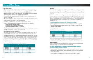
TOTAL TPE SOLUTIONS
©2004 GLS Corporation Rev. 082704
North American Headquarters
833 Ridgeview Drive
McHenry, Illinois 60050 U.S.A
1-815-385-8500 phone
1-800-457-8777 toll-free
1-815-385-8533 fax
email: info@glscorp.com
www.glscorp.com
Offices in The Netherlands and Hong Kong
011 31 113 551 093 phone (Netherlands)
011 (852) 2690 5330 phone (Hong Kong)
1
Introduction
GLS is the recognized leader in the overmolding of thermoplastic elastomers
(TPEs). Our overmoldTPEs have excellent adhesion to a wide variety of substrates,
from polyolefins, such as polypropylene and polyethylene, to engineering resins,
such as PC, ABS, acetal and nylon.
GLS has developed several innovative technologies that have continued to set
the standard in overmolding. Our overmolding product line includes a variety of
TPE technologies designed to deliver optimum adhesion to many engineering
plastics in both insert and two-shot molding processes.
When working with GLS, you get the benefit of a world-class
application development team spanning:
• Component design knowledge.
• Valuable tooling input.
• Creativity in molding process knowledge and material combinations.
• Compound development to meet specific application requirements.
The GLS Overmolding Guide is a comprehensive discussion of issues that are
critical to achieving high quality overmolded products. This guide is a compilation
of over thirteen years of experience in the development, design and processing
of overmolding TPEs, based on contributions from a variety of GLS and
industry sources.
Table of Contents
Introduction 1
Overmolding 2
Material Selection 4
Part and Mold Design 6
Material Handling and Preparation 17
TPE Injection Molding 18
Overmolding Processing – Maximizing Adhesion 21
TPE Injection Molding Troubleshooting 23
TPE Overmolding Troubleshooting 28
Index 30
3
2
Overmolding
Overmolding is the injection molding process where one material (usually a TPE) is molded
onto a second material (typically a rigid plastic). If properly selected, the overmolded TPE will
form a strong bond with the plastic that is maintained in the end-use environment. The use
of primers or adhesives is no longer required to achieve an optimum bond between the
two materials.
Overmolding can be used to enhance many features of product designs, including:
Overmolding Process Types
Two injection molding processes dominate the manufacture of overmolded products: insert molding
and multi-shot injection molding.
Insert Molding
The most widely used process is insert
molding, where a pre-molded insert is
placed into a mold and the TPE is shot
directly over it (Figure 1). For molders,
the advantage
of insert molding is that conventional
single shot IM machines can be used
(new machinery expenditures are not
necessary), and the tooling costs associated
with insert molding are lower than with
multi-shot processing.
Multiple Material Molding
Multiple material, also known as two-shot (or multi-shot), molding requires a special injection
molding machine that is equipped with two or more barrels, allowing two (or more) materials to
be shot into the same mold during the same molding cycle.
A molder will choose multi-shot molding to reduce cycle times, achieve superior part quality and
reduce labor costs.
Face Mounted Replaceable Insert
Magnetized to Hold Metal Insert
TPE Overmold Substrate
Figure 1. Spring-loaded insert for metal tolerances.
Safety Ergonomics Product Functionality
• Improved grip in dry • Increase in comfort level. • Water resistant seal.
and wet environments. • Sound absorption.
•Vibration damping. • Electrical insulation.
Overmolding Process Selection
A processor will weigh numerous factors when choosing the appropriate manufacturing method
for the application. The most critical decision factors are production scale economics, local labor
costs, available equipment and the materials selected.
Generally, insert molding is the process of choice when annual production volumes and local labor
costs are low. For higher volume production programs (over 250,000 units annually) or areas with
increased labor costs, multi-shot molding operations are the method of choice.
With any overmolding application, the challenge is in achieving maximum adhesion between the
TPE and the substrate. For some overmolding TPEs, there may be a significant difference in bond
strength between multi-shot and insert molding. Even if an excellent bond is achieved with two-shot
molding, the same material may have poor bond strength when insert molded. Thus, a complete
understanding of the TPEs, engineering plastics, and associated details about molding these materials
is essential to produce high-quality finished products.
5
4
Adhesion Requirements
When selecting a TPE for an overmolding application, the substrate type should be considered.
Not all GLS TPEs will bond to all types of substrates; for example, a Dynaflex®
TPE that bonds
to polypropylene (PP) will not adhere to polycarbonate (PC).
GLS offers a diverse product line of TPE compounds and alloys for overmolding onto a variety of
substrates. Most Dynaflex®
, Versaflex®
and Versalloy®
compounds are suitable for two-shot or
insert molding with a polypropylene (PP) as the insert or substrate.
The GLS OvermoldingTPEs (Versaflex®
andVersollanTM
) are specially formulated
to bond to a variety of thermoplastics, including:
• Polycarbonate (PC)
• Acrylonitrile Butadiene Styrene (ABS)
• PC/ABS
• Standard and Modified* Nylon 6, Nylon 6/6, Nylon 6,6,6
• Copolyester
• Polystyrene (PS)
• High Impact Polystyrene (HIPS)
• PC/PETG
• Acetal (POM)
• Polyphenylene oxide (PPO)
• Alloys or blends of the above
*Glass-filled, impact-modified, and/or heat-stabilized versions.
For more information regarding specific overmolding TPEs and their corresponding substrate
materials, please refer to the GLS Overmolding Product Selector Guide.
Material Selection
The most common word used to describe a soft touch overmold is “feel” — but the term
itself is very difficult to describe. When a designer wants the product to feel “grippy” or
“squishy”, what exactly does this mean in terms of material properties?
Basically, the “feel” of a soft touch overmold is dependent upon a combination of material
properties (hardness, modulus, and coefficient of friction), texture and the TPE wall thickness.
Thickness Effects
When choosing a soft touch TPE, designers usually ask for the softest material available. What
they do not know is that the soft durometer of a TPE adds little value to the concept of “cushion”
when the thickness of the TPE is below a certain point (typically > 0.040"). This means that the
thinner the TPE overmold, the harder it will feel — the actual hardness effect is dependent on
the thickness of the TPE overmold. One way of getting around this issue is to incorporate multiple
ribs that are placed closely together to create the perception of thickness without using a large amount
of material. This technique is used often in personal care grips.
Hardness vs. Modulus
One common myth in the TPE industry is that the durometer (or hardness) of a material is directly
related to its flexibility. This is not always true; for example, a 65 Shore A SEBS material is
much more flexible than a 65 Shore A TPU. Instead of using Shore Hardness, a more suitable
measure of flexibility is the flexural modulus, which measures a material’s resistance to bending.
A higher flexural modulus typically means that a material will feel more stiff and unyielding.
Coefficient of Friction
When two surfaces are dragged flat against each other, the resulting resistance is characterized as
friction. The coefficient of friction (COF) characterizes the degree of force required to move one
surface across another — either from a complete stop (static friction) or when the surface is already
moving (kinetic friction). Typically, TPEs are described as rubbery or “grippy” — GLS has the
capability to customize the COF according to the requirements of the application — from smooth
and silky to extremely tacky.
One area that product designers often misunderstand is the relationship between durometer and
COF. Most believe that the softer the TPE, the greater the COF — this is a very general statement
and is not true in all cases. There are several GLS products in the 40 Shore A Hardness range that
have varying COFs.
For assistance in choosing the material with the optimum COF for an application, please contact
your GLS representative.
7
6
Typical Shrinkage, %
Series Flow Direction Cross Direction
Dynaflex®
1.5-2.1 0.7-1.3
Versalloy®
0.9-1.3 0.9-1.3
Versaflex®
1.1-1.7 0.7-1.3
VersollanTM
1.1-2.1 0.5-1.0
Table 2. Typical shrinkage for GLS TPEs*
.
*These shrinkage values are a range that is representative of all of the TPE grades in a specific product family and should not be
used as guidelines for part and mold design. Please refer to Product Data Sheets for specific shrinkage values for each individual grade.
Shut-Off Designs
There are two different types of shut-off designs with the purpose of minimizing flashing of the
TPE or reducing the chance of peeling (delamination) of the TPE.
To reduce the opportunity for peeling, the overmold should be designed in
accordance with the following guidelines:
• The surface of the TPE should be flush with the non-overmolded section of the substrate.
• The edge of the TPE should be at a deeper level than the surface of the non-overmolded
section of the substrate.
• Do not design the TPE edge so that it is even with or over the edge of the part.
Shrinkage
Due to the wide variety of chemistries of GLS overmolding TPEs, their shrinkage characteristics
can vary significantly. Table 2 summarizes general shrinkage ranges for the various GLS product
families. Typical shrinkage values for specific GLS products are located on the GLS Product Technical
Data Sheet.
It should be noted that these shrinkage values are guidelines only; the shrinkage of a material is
extremely dependent on the material chosen, the part/mold design, and the processing conditions
used to mold the part. The shrinkage guidelines provided by GLS are based on a particular specimen
geometry (rectangle/plaque) and are determined using a specific type of injection molding machine.
As a result, prototyping is highly recommended to assist in predicting the shrinkage effects of a
particular GLS TPE.
The following process parameters may increase part shrinkage:
• Mold and melt temperatures that are too high – results in heat sinks due to shrinkage.
• Mold and melt temperatures that are too cold – leads to molded-in stresses that may
contribute to part warpage.
• Low pack pressures.
Part Design Basics
•The wall thickness of the substrate and overmold should be as uniform as possible
to obtain the best molding cycle time. Wall thicknesses ranging from 0.060" to 0.120"
(1.5 mm-3 mm) will ensure good bonding in most overmolding applications.
• If the part requires the use of thick TPE sections, they should be cored out to minimize
shrinkage problems, reduce the part weight and lower cycle time.
• Transitions between wall thickness should be gradual to reduce flow problems, such as
back fills and gas traps.
• The use of radii (0.020" or 0.5mm minimum) in sharp corners helps reduce localized stresses.
• Deep, unventable blind pockets or ribs should be avoided.
• Long draws should have a 3-5° draft per side to aid component ejection.
• Properly designed deep undercuts are possible with GLS TPEs (<60 A Hardness) if:
- The part does not have sharp corners.
- An advancing core is used when the mold opens.
- The elastomer is allowed to deflect as it is ejected.
• The TPE thickness should be less than or equal to the thickness of the substrate to prevent
warpage; this is especially critical for long, flat geometries.
Flow Length (L) and WallThickness (T)
There are two main factors that affect the maximum achievable flow length for a specific TPE: the
individual TPE flow characteristics and the process conditions used in the overmolding process.
The flow characteristics of a TPE can be quantified by performing a spiral flow test. Spiral flow
testing, which has been traditionally used for thermoplastics, provides the processor with a comparative
analysis of a material’s ability to fill a part. The spiral flow lengths of various GLS product lines at
two injection speeds (3 in/sec and 5 in/sec) are summarized in Table 1. For applications with higher
bond strength requirements, shorter flow lengths are advisable. Alternatively, mechanical interlocks
are highly recommended.
Table 1. Typical Flow lengths achievable with GLS compounds*.
Flow Length, inches (cm)
Series InjectionVelocity, 3 in/s (8 cm/s) Injection velocity, 5 in/s (13 cm/s)
Dynaflex®
D 13-15 (33-38) 18-20 (46-51)
Dynaflex®
G 12-22 (30-56) 18-30 (46-70)
Versaflex®
9-16 (23-41) 13-26 (33-66)
Versalloy®
18-20 (46-51) 30-32 (76-81)
VersollanTM
12-17 (30-43) 19-22 (48-56)
*Spiral flow tests performed using a 0.0625" (1.6mm) thick, 0.375" (9.5mm) wide channel at 400˚F (204˚C).
Part and Mold Design
8 9
To reduce the probability of flashing the mold, the overmold should be designed
with the following guidelines:
• Provide a 0.015"– 0.030" (0.38mm – 0.76mm) deep groove on the substrate,along the edge of
theTPE overmold (Figure 2). The steel should have positive shut-off in the groove. In addition,
shrinkage of both the TPE and substrate should be considered.
• When metal or other non-compressible substrates are used, provide springs underneath
the steel sections shutting off on the substrate to prevent flashing due to a steel insert with
a poor fit.
The fundamental bond of GLS
TPE over the rigid substrate can
be provided by a combination of
three basic methods:
• Molecular adhesion.
• Mechanical design techniques.
• Mechanical interlocks.
Figure 3 illustrates three mechanical
interlock design options that can be
utilized to optimize finished component
bond strength.
Utilizing texture on the TPE overmold
surface is a good way to impart a
unique surface feel to the product
and minimize the appearance of surface
defects. It should be emphasized that
certain textures will lead to a perceived hardness that is higher (or lower) than the actual hardness
of the TPE. As a result, the TPE surface texture should be taken into consideration during the
material selection phase of the product development process.
Figure 3. Types of successful mechanical interlocks.
TPE
Substrate
TPE
Substrate
Figure 2. Examples of shut-off designs.
General Mold Design Considerations
• The viscosity of GLS overmoldingTPEs is very shear dependent and this should be considered
when designing the molds and setting the molding process conditions.
• Start with smallTPE injection gates to obtain bestTPE fill with minimum cosmetic gate vestige.
Large gates should be avoided.
• Gates should be located at the thickest TPE wall section.
• Thought should be given to proper component ejection from the tool to minimize marks
on the soft elastomer surface.
• It is critical that adequate cooling is provided to the TPE cavity through proper mold cooling
techniques to minimize cycle time.
• Flow ratios should not exceed 150: 1L/T as an absolute maximum for most overmolding
applications.
Mold Construction
GLS overmolding TPEs are generally non-abrasive and non-corrosive. The choice of tool steel will
depend on the quantity and quality of parts to be produced, the longevity of mold required, and
the type of rigid substrate being used in the application. If a reinforced substrate material is used,
high hardness abrasion resistant steel will be required. For high volume two-shot or insert molded
component production, the initial expense of high quality injection mold tooling is a sound
investment. P-20 steel is typically used for mold bases and ejector plate, while H-13 steel is used for
cavity and core plates. For applications that require optimum cooling, beryllium copper cores
are common.
Most GLS materials replicate the mold surface fairly well. A polished mold is required to produce
a glossy surface or optimum clarity. To produce a part with the matte appearance of a thermoset
rubber, a rougher mold surface is required. In general, an EDM finish will produce a good surface
and good release from the mold. Vapor honing, sand or bead blasting and chemical etching may
also be used to produce surfaces with varying degrees of gloss and appearance. To aid in release,
the cavity or core may be coated with a release coating, such as PTFE impregnated nickel, after it
has been given a sand blast or EDM finish.
10 11
Mold Layout and Support
For multi-cavity tools, the cavity layout should be physically balanced. In a balanced system, the
TPE melt flows to each cavity in equal times under uniform pressure. An unbalanced runner may
result in inconsistent part weights and dimensional variability.
Figures 4 and 5 illustrate examples of
balanced and unbalanced runner systems.
In insert molding applications, proper
support of the plastic insert is required.
Without support, the plastic substrate
can deform due to the TPE injection
pressure. In extreme cases, the insert
will break or the TPE melt will impinge
through the plastic insert. Flashing in
certain areas of the tool can also result
from displacement of the insert within
the mold cavity. This is usually not an
issue with two-shot molding because the
first shot is automatically supported on
the “B-half” of the tool.
Venting
It has been well-established that the lack of adequate venting is a processing issue for both overmolding
production and standard injection molding. If vents are not incorporated into the mold design, the
adhesion of the TPE to the substrate can
be critically affected in specific areas of
the part where air is trapped in the cavity
during injection. As the TPE melt is
injected into the mold cavity, the air in
the cavity must be able to effectively exit
the tool. This is usually achieved via the
addition of vents at the ends of flow (full
peripheral venting is the best solution).
Figure 6 provides an illustration of
appropriate venting.
12
11
10
9
8
7
6
5
4
3
2
1
Figure 5. Unbalanced runner systems.
Runner Configuration and Design
For conventional cold runner tools, full-round runners are best because they provide the least resistance
to flow and minimize TPE cooling in the runner system. Cooling is minimized because full round
runners have less surface area and therefore keep the TPE material molten longer.
The second most efficient runner
cross-section is the modified trapezoid.
This type of geometry most closely
simulates a full round runner, but
requires machining in only one
tool plate.
Figure 7 illustrates typical runner design
guidelines. Runner dimensions rarely
exceed 0.3" diameter, even for the
primary runner.
Cold Slug Wells
Cold slug wells should be used at each
runner transition (90° turn or division).
They should be placed in the direction
of the feeding flow front and at the base
of the sprue (Figure 8). The use of cold
slug wells will aid in removal of the
solidified leading TPE edge.
Vent 0.0005 – 0.001 in
0.013 – 0.025 mm
Vent 0.005 – 0.010 in
0.13 – 0.25 mm
Part Cavity
To Atmosphere
Vent 0.040 – 0.080 in
1.0 – 2.0 mm
Part Cavity VENT
RUNNER
Figure 6. Example of appropriate venting.
TPE Venting Dimensions:
Land Length: Minimum 0.040" or 1mm (where vent depth is cut).
Depth of Land (vent run out): >0.060" (>1.5mm)
Vent Depth: 0.0005"– 0.001" (0.013mm – 0.025mm) deep — 0.00075" (0.019mm) optimum.
+
+
+
D4 = 1.0
D3 = D4
D2 = 1.4D3
D1 = 1.4D2
D1
D3
D2
D4
A2 = Secondary Runner
Primary Runner = A1 A3 =Tertiary Runner
A1>A2>A3 = Cross Sectional Area of Runners
Figure 7. Runner design guidelines.
Radius at
RunnerTransition
W
Ejector or "Sucker-pin"
"Cold Slug" = 1.5(W)
Figure 8. Runner system with cold slug well.
3
1
2
4
6 7
8
9 10
11
12
13
14
15
16
5
2
3
4
5 6
7
8
9
10
11
12
13
14
15
16
1
Figure 4. Balanced runner systems.
12 13
Sprue Pullers
Sprue pullers are used to pull the sprue out of the A-half of the tool so that the plastic may be
ejected automatically out of the mold using an ejector pin. For GLS materials with hardnesses over
50-90 Shore A, a sprue puller with a
Z-type may be used to pull the sprue out.
The sprue puller should be polished,
while the sprue and runners should have
a rough EDM finish. This would enable
the plastic to stick to the sprue puller
as it is withdrawn. In the case of softer
GLS materials, it may be necessary to
use a more aggressive sprue puller such
as a pine tree design (Figure 10). It is
extremely important to position cooling
channels close to the sprue puller since
this can help the plastic to harden
around the puller before it is withdrawn.
In the case of three plate tools, a sucker
pin with a simple spherical end is suitable.
This would help pull the runners out of
the floater plate. A low reverse draft of
10-15° may be added to the sides so as
to help form a slight undercut. As stated
earlier, it is very important to incorporate
cooling channels on either side of the
sucker pin. In addition, a rough EDM or sandblast finish should be used for the runners and a
polished finish for the sucker pins. This should help the sucker pin to pull the runner out more
easily. A more aggressive sucker pin may pull the runners out, however it may be difficult to
automatically remove the runners off the sucker pin once the mold is open. Sprue pullers may not
be necessary when hot sprues are used.
Gate Design and Location
Most conventional gating types can be used in the molding of GLS TPEs.
The type of gate and the location, relative to the part, can affect the following:
• Part packing.
• Gate removal or vestige.
• Part cosmetic appearance.
• Part dimensions, including substrate warpage.
5º
3º
O
Figure 9. Conventional sprue.
Sprue
Sprue Puller
Primary Runner
Sleeved Ejector
Figure 10. Pine tree sprue puller for soft GLS TPEs.
The type of component gating is
dependent on both the finished part and
injection mold design. The gate location
is critically important; the gate should be
located at the thickest section to minimize
molded-in stresses. To prevent the
chances of jetting, locate the gate in an
area where the flow will impinge on a
cavity wall. For automatically degating
tools, the highly elastic nature of soft
TPEs makes gate designs such as
submarine gates or three plate tools with self-degating drops more difficult. To assure the gates will
break at a specific location, they should have a short land length to create a high stress concentration.
Tab/Edge Gate
Tab and edge gates (Figure 12) most commonly utilize a conventional sprue and cold runner system.
They are located along the tool parting line. The part design may use a small undercut where the
gate meets the part to minimize gate vestige protruding above the part surface.
Advantages of tab and edge
gates are ease of:
• Fabrication.
• Modification.
• Maintenance.
For styrenic-based TPEs, the gate depth (D) should be 25-35% of the TPE component’s wall
thickness at the gate entrance; 35-50% for urethane-based TPEs. Common practice is to start
“steel safe”, as it is always much easier to enlarge the gate size (no welding required). A good
starting point for the gate width should be 1.0-1.5 times the gate depth. The gate area in the
mold may be included as a removable insert to facilitate gate maintenance or modification.
Figure 11. Buttonhead sprue puller for automated removal.
Mold
Mold
TPE
Plastic Substrate
Small Radius
1 – 1.5D = Land
T
Figure 12. Tab/edge gate.
Submarine (Tunnel) Gate
Submarine or tunnel gates are
self-degating; during part ejection,
the molded part and runner are
separated by the tool steel. To promote
degating, a radius can be located at the
end of the sub-gate; typical dimensions
are 1.5-2 times the radius of the gate.
Figure 13 shows a typical design of a
submarine gate.
Fan Gate
A fan gate is a variation of a tab gate
(Figure 14). The fan gate distributes
material into the cavity more evenly than
other gate designs. It is normally used in
parts that require a high degree of flatness.
Sprue or Direct Gate
Sprue, or direct gating is often used on prototype parts; the cavity is placed directly in line with the
center of the sprue. If the product design requires a sprue gate, a hot sprue is preferred over cold
because it reduces scrap, decreases cycle time, and allows for easier processing.
Sprue gating is not recommended for production tools or for aesthetic parts due to the potential
for “cold-slugs” on the part surface. The sprue will also need to be manually trimmed. If this type
of gate is desired, both the sprue length and diameter should be as short and small as possible.
15
14
Typical Fan Gate Flow Pattern
SideView
Land
TPE Overmold
t
T
Substrate
D
TopView
W
Land = 0.060 – 0.08"
t = 0.15 – 0.30T
W = 2D minimum
Figure 14. Conventional fan gate.
GateType Advantages Disadvantages
Edge/Tab/Pin Gate • Appropriate for flat parts. • Post-mold gate/runner removal.
• Easy to machine and modify. • Larger gate vestige.
Submarine Gate • Auto gate removal. • More difficult to machine.
• Minimal gate vestige. • More difficult to extract.
Back Gating (through • No gate vestige on front side • More complex.
pin & hole in substrate) of part. • Post-mold trimming.
• Potential surface sink.
Diaphragm Gate • Concentricity. • Post-molding gate/runner removal.
• Appropriate for round parts. • Scrap.
• No knit lines.
Pin Gate (3-plate) • Auto gate removal. • Requires floater plate.
• Minimal gate vestige. • More scrap.
• Localized cooling. • Higher tool cost.
Valve Gate • Minimal gate vestige. • High tool cost.
(hot runner systems) • Positive shut-off. • Higher maintenance.
• Minimizes post pack.
Gate Location Considerations
Locate Gates:
• At the heaviest cross section, to facilitate part packing and minimize voids and sink.
• To ensure a flow path that will yield optimum adhesion.
• To minimize obstructions in the flow path (flowing around cores or pins).
• To minimize jetting (in thin-walled components).
• Where potential residual molded-in stresses around the gate will not affect part function
or aesthetics.
• To minimize flow marks in critical cosmetic areas.
• To minimize potential knit lines (particularly in components with two or more gates).
• To allow easy manual or automatic degating.
• To minimize flow path length (<150 L/T).
Table 3. Advantages and disadvantages of various gate types.
Primary
Runner
TopView Plastic
A D A
TPE
TPE
Plastic
Section A-A
30˚ Reference Angle
Gate Dia. 0.04 – 0.125" Typical
2D
Figure 13. Submarine gate.
17
16
Material Handling and Preparation
Drying
The moisture level of both the overmold grade as well as the substrate can adversely affect adhesion.
It is critical that hygroscopic materials are dried prior to molding.
Drying is required for some specialty GLS TPEs, including Versollan Elastomer alloys. Drying
should be done using a desiccant dryer with a dew temperature set at -40˚F (-40˚C). For the
Versollan grades, a moisture level at or below 0.06% is recommended; typical drying conditions
are 4 hours minimum at 120-140˚F (50-60˚C). Refer to the individual GLS Product Technical
Data Sheet for specific drying recommendations.
Coloring
When overmolding TPEs, care should be taken when considering color concentrates. While
there are a variety of color concentrate carriers available, the adhesion of the TPE to the substrate
can be seriously and even adversely affected if the carrier is incompatible with the chemistry of
the TPE.
The most common color concentrate carrier is PP because it is compatible with many commercially
available TPE products (for both single component molding and overmolding PP applications). As
new TPE technologies emerge to adhere to engineering plastics like nylon and PC/ABS, PP-based
color concentrates may not be the best choice for optimized adhesion characteristics. Instead,
alternative carriers, such as EVA, LDPE or polyurethane may be required. Coloring suggestions
for specific GLS overmolding products can be found in the GLS Product Technical Data Sheet.
Regrind
For insert molding applications, regrind may be used if clean, non-degraded TPE scrap is generated
during the process (sprues and runners). Typical loading levels are 20%, however higher levels
of regrind are tolerated in black color TPEs. Natural products, light colored or clear compounds
may show contamination or discoloration unless regrind cleanliness is properly controlled. When
a high percentage of regrind is used, or there is a prolonged residence time in the barrel, organic
pigments (used to produce yellow, red, blue and green colors) are more likely to discolor.
Regrind is not an option for most critical appearance two-shot molded components.
Hot Runner Manifold Systems
Hot runner tool designs are often used for GLS overmolding TPEs. As with conventional systems,
the runner design should be naturally or geometrically balanced. All passages should have highly
polished circular cross sections with gentle bends to minimize the possibility of stagnation zones.
Externally heated manifolds are best. Internally heated systems, which use torpedo heaters, are
not recommended because they have hot spots, stagnation zones and partially solidified material
clinging to the walls.
Valve Gates
For hot runner tools, valve gates are recommended when production volumes are high and part
appearance is critical. In parts that require stringent quality requirements, a valve gate will leave a
ring that is barely visible on the surface of the part. After entering the cavity, the melt is not
required to freeze before the valve is closed. Screw recovery can start immediately once the valve
is closed, thus reducing the overall cycle time.
For very thick wall parts, with the potential for sinks or shrink voids, the valves are held open
longer to allow for sufficient packing of the part. Valve gate elements need to be insulated from
the mold plates to maintain proper temperature control. Due to the low viscosity of some GLS
overmold grades, the pins need to be tight to prevent valve leakage or hair flash. Individual heater
controls at each gate allow for finer control of the melt temperature and viscosity, as well as filling.
A valve gate can be located below the part surface or hidden in the part detail. Dependent on the size
and thickness of the part, the gate diameter can vary between 0.030" and 0.125" (0.8 mm–3.2 mm).
19
18
Machine Selection
Molding machines with conventional reciprocating screws are recommended. Newer computer
controlled machines have the ability to better control critical molding parameters and are preferred
for multi-cavity tools and high production quantities. Machines with programmable injection
rates to “profile” the shot, and independent first and second stage pressures can produce better
quality parts. This results in finished components with improved part weight and dimensional
control. Older molding machines that control the shot size by position are preferable to machines
that only control the process by pressure and/or time.
The clamp capacity necessary for general purpose GLS compounds is 2-3 tons per square inch
multiplied by the total projected area of the cavities and the runner system. This is lower than
most other TPEs. If possible, use a machine that utilizes 25% to 75% of the barrel shot size capacity.
This will result in better temperature control of the material and minimal material residence time
at high temperature. The typical material residence time for GLS overmolding compounds should
be no more than 4-5 minutes maximum. In most two-shot molding applications, the TPE shot
size is considerably smaller than the plastic substrate shot size. If available, use an injection unit
sized to minimize the TPE residence time.
During startup, choose a smaller nozzle diameter, which will help to produce shear heating during
injection and generate less cold slug material. Suggested starting nozzle diameters are 1/16" to 3/16"
(1.6mm-4.8mm). General-purpose (GP) screws are suitable for most GLS TPEs. Compression
ratios between 2.0 and 3.0:1 will effectively control GLS overmolding TPEs during the injection
molding process. Barrel/screw combinations should offer a minimum 24/1 L/D ratio.
Purging
If the press is idle for more than 10 minutes, purge thoroughly with a low flow (0.5-2.5 melt flow)
polyethylene (PE) or polypropylene (PP) before restarting component production. To prevent flashing,
restart the machine using a reduced shot size and gradually increase it to the previous setting.
Injection Pressure and Injection Speed
Typically, the required first stage injection pressure to fill a TPE cavity is 300 to 800 psi, depending
upon the number of cavities and the mold runner layout. To achieve the benefits of shear-thinning,
the injection speed should be adjusted to fill the mold in 1-3 seconds (varies with material).
A higher shear rate can be readily achieved through greater TPE melt velocity (shot speed) and
higher first stage injection pressure.
Mold Temperature
To prevent mold condensation and the resultant water contamination in the cavity, the mold
temperatures should be set above the dew point temperature in the molding area. Mold
temperatures may have to be increased if there are long or thin sections of the part that cannot
be filled by adjusting other molding parameters. TPE mold temperatures of 70-120˚F (21-49˚C)
are typical. Accurate mold temperature is critical when running molds with core lifters. When
using these ejection systems, differential thermal expansion of the mold may cause the lifter to jam.
Material Flow Behavior
• Most GLS overmolding compounds have relatively low viscosity characteristics. They are
shear responsive and their viscosity is reduced when they are processed at high shear rates.
This helps them flow into and fill thin walled sections commonly encountered in overmolding.
• The shear thinning behavior of GLS TPEs should be considered when designing injection molds
and optimization of molding conditions.
Figure 15 illustrates the range of viscosity
of GLS overmolding TPEs. The lower end
of the range is typical for most GLS TPEs.
For the viscosity data of a specific GLS
TPE, refer to the individual product
technical data.
Due to the shear sensitivity of TPEs,
their injection molding process is slightly
different than that of engineering
thermoplastics. Unlike most thermoplastics,
melt temperature alone is not the most
effective method of controlling the TPE
molding process. Ideally, the goal is to obtain the lowest melt viscosity of the molten TPE through
a combination of shear rate and temperature adjustments.
Shear rate in modern molding machines can be controlled through the use of:
• TPE melt velocity.
• First stage injection pressure.
• Smaller gate size.
GeneralTPE Injection Molding Guidelines
The following are basic principles for optimizing the molding process for GLS TPEs:
• During start-up, the molding parameters should be set at the mid-point of the TPE
supplier’s recommendations.
• Shear rate adjustments should be the primary method used to control TPE melt viscosity.
TPE melt temperature adjustments should only be used to fine-tune the process.
• To minimize shrinkage issues, adjust second stage pressure as necessary to insure the TPE
melt is fully packed into the mold cavity.
• Utilize “cushion” properly during the mold filling process.
TPE Injection Molding
Injection
Molding Range
Compression
Molding Range
Extrusion
Range
Viscosity,
Pa.s
Shear Rate, 1/s
10,000
1,000
100
10
1
10 100 1,000 10,000 100,000
*Measured at 390˚F (200˚C)
Figure 15. The effect of shear rate on the viscosity of GLS
styrenic TPE compounds.
21
20
Substrate Preparation and Molding
If insert molding is the process of choice, the preparation and molding of the insert can be critical
to achieve optimal adhesion between the TPE and the substrate. If an insert surface is not clean,
loss of adhesion between the TPE and substrate is a strong possibility. Ideally, it is best if the
inserts are molded, then transferred immediately to the second mold to inject the TPE.
The insert should be molded in accordance with supplier recommendations (drying, adequate
melt and mold temperatures). If the inserts are molded and stored prior to the overmolding
phase of the process, they should be well-protected from contamination sources like dirt, dust,
etc. Skin oil can also affect the TPE adhesion to the insert, so hand protection should be worn
when handling the inserts. Mold release should not be used in either the insert or the overmolding
processes, as the lubricants can seriously degrade the TPEs bond to the insert.
Studies have demonstrated that preheating the insert prior to overmolding can be very beneficial
to the end quality of insert molded parts. The optimum insert temperature will vary, depending
on both the insert material and the type of TPE used.
Preheating nylon inserts is strongly discouraged. The adhesion of the new Versaflex®
OM6100
series is outstanding, with no modification of the substrate. In fact, preheating the nylon insert
can have a negative impact on adhesion.
TPE Melt Temperature
The TPE melt temperature is one of the most critical injection molding parameters for overmolding
applications. A common practice is to equate nozzle temperatures with melt temperature. In many
cases, this practice is misleading, since the real temperature of the melt can vary significantly from
the nozzle’s temperature. The size of the barrel, shot size and the calibration of thermocouples are
all factors that can lead to inaccurate melt temperature readings.
The actual temperature of the melt can be best quantified by measuring the temperature of a TPE
airshot using a pyrometer. In many cases, the melt temperature of the TPE is lower than the nozzle
temperature. Correspondingly, lower melt temperatures can affect adhesion quality.
The melt temperature of the TPE must be selected based on the substrate used and target bond
level desired in the finished component. To achieve optimal bond strength, higher temperatures
using melt temperature guidelines for specific GLS products as a starting point is suggested. In
some critical applications, this temperature can be close to the upper processing temperature limits
for the TPE.
In order to reduce residence time at high temperatures, the rear zone temperatures should be
reduced as much as possible, while maintaining the last zone and nozzle at the high processing
temperature. For specific GLS overmolding TPEs, start-up temperature settings are included
in the GLS Product Technical Data Sheet to assist molders to determine optimal melt temperatures.
Overmolding Processing — Maximizing Adhesion
It is a common practice to use two mold temperature controllers while running GLS materials.
If sticking in the A-half of the tool is an issue, reduce its temperature as a possible means of improving
ejection performance.
Cooling Time
The required cooling time is dependent on the temperature of the melt, the wall thickness of the
part and the quantity of cooling available. Harder grades will set up faster than softer grades and
are easier to eject. Overmolded parts will take longer to cool because the TPE is only cooled from one
side as the plastic substrate acts as a thermal insulator. The cooling time for overmolded parts will
be approximately 15 to 40 seconds for every 0.100" (2.5mm) of overmold wall thickness.
Given a final part design and GLS TPE material selection, there are three
primary variables that have an impact on cycle time:
• Diameter of cooling line.
• Geometric orientation (distance) of cooling line with respect to the tool cavity.
• Flow rate of the water through the cooling system.
23
22
TPE Injection MoldingTroubleshooting
Problem: Beach marks and uneven shine
Possible Cause
High molecular weight
compound in highly
polished mold.
Corrective Actions
• Adjust melt velocity and 1st stage injection pressure.
• Change to a lower molecular weight compound.
Consult with GLS representative.
• Texture mold cavity surface (EDM, sandblast, etc.).
Problem: Bubbles
Possible Cause
Melt temperature is too high
(injection speed too fast).
Gas entrapment.
Corrective Actions
• Lower melt temperature.
• Lower injection speed.
• Increase gate size.
Problem: Burned component edges (with short fill)
Possible Cause
Poor venting.
Corrective Actions
• Lower injection speed.
• Add vents to mold design, 0.0005"- 0.008" (0.13 mm - 0.20 mm) deep.
• Clean vents if clogged.
Problem: Burnt odor, parts have yellow cast
Possible Cause
Material degradation.
Corrective Actions
• Reduce TPE melt temperature (particularly in rear of machine).
• Reduce residence time to 2 minutes maximum.
• Reduce hot runner system melt temperature.
• Minimize dead spots in hot runner manifold.
• Purge barrel and hot runner.
• Reduce regrind level to <15%.
Problem: Dimensions out of specification
Possible Cause
Improperly packed part.
Loss of control of shrinkage.
Corrective Actions
• Check hold pressures (no drop).
• Check that cushion was maintained.
• Increase cooling time.
• Check tool dimensions.
Additional Factors that Affect Adhesion
• Grade of plastic substrate (glass-filled, mineral-filled, heat-stabilized, lubricated).
• The more polymer on the substrate surface, the better the adhesion.
• Ensure that the chosen TPE is designed to bond to the substrate.
• Appropriate TPE thickness — too thin can lead to delamination.
• Use of mechanical interlocks in the component design.
• Proper shut-off design.
• Adequate venting is critical, especially at ends of flow.
• Type of color concentrate carrier used in both the plastic and the TPE.
• Pre-drying of the TPE overmold material, if required.
• Substrate preparation and cleanliness.
• Higher TPE melt temperature generally provides higher bond strength.
• Control melt temperature by injection speed, 1st stage pressure, then barrel temps
(to fine-tune).
25
24
Problem: Jetting
Possible Cause
High viscosity flow.
Injection speed is too fast.
Incorrect gate location.
Corrective Actions
• Increase TPE melt temperature.
• Decrease injection speed.
• Relocate gate so that the melt impinges off wall as it enters cavity.
Problem: Non-uniform color
Possible Cause
Poor dispersion.
Contamination.
Corrective Actions
• Ensure that proper color concentrate carrier is used.
• Increase machine back pressure and/or screw RPM.
• Change the color concentrate carrier to a material with a lower
melt temperature.
• Increase temperatures.
• Purge barrel thoroughly.
• Check for cleanliness of regrind.
Problem: Off-color part or odor
Possible Cause
Contamination.
Material degradation.
Corrective Actions
• Check for contamination in material handling and regrind (if used).
• Reduce TPE melt temperature (particularly in rear of machine).
• Reduce residence time to 2 minutes maximum.
• Reduce hot runner system melt temperature.
• Minimize dead spots in hot runner manifold.
• Purge barrel and hot runner.
• Reduce regrind level to <15%.
Problem: Heat sinks
Possible Cause
Material shrinkage.
Melt temperature is too high.
Part is too thick in areas
where sinks or voids occur.
Corrective Actions
• Increase total cooling time.
• Reduce melt temperature.
• Reduce part thickness.
Problem: Ejector pin marks
Possible Cause
Pack pressure is too high.
Parts are soft during ejection.
Ejection force is too high.
Corrective Actions
• Reduce pack pressure.
• Increase cooling time.
• Increase water flow rate in cooling time.
• Reduce mold temperature.
• Texture ejector pins and mold surface for better release.
• Increase size of pins.
• Consider use of pneumatic poppets to assist in component release.
Problem: Flash
Possible Cause
Injection pressure is too high.
Shot size is too high.
Material viscosity is too low.
Insufficient clamp capacity.
Vents are too deep.
Corrective Actions
• Reduce 1st stage injection pressure and fill time.
• Decrease shot size.
• Reduce injection speed (melt velocity).
• Reduce TPE melt temperature in 10˚F/C increments.
• Increase machine clamp tonnage (min. 2 tons/sq. in.) with a
larger press.
• Reduce thickness of the vents (max. 0.001" or 0.025 mm depth).
Problem: Flow marks, folds and back fills
Possible Cause
Melt temperature is too low.
Filling from thin to thick
sections.
Surface irregularity.
Uneven filling of section.
Corrective Actions
• Increase melt temperature.
• Reposition the gate to a thick section.
• Surface texture can be added to part design and steel wall cavities.
• Relocate gate to balance the flow or reduce the runner diameter.
27
26
Problem: Voids
Possible Cause
Insufficient pack pressure
during material solidification.
Corrective Actions
• Increase 2nd stage pressure and melt velocity.
• Increase the gate size up to 40% of part wall thickness (max).
• Relocate the gate to the thickest wall section.
Problem: Splay/streaks, silver streaks
Possible Cause
High shear in the material.
Moisture in material
(if hygroscopic).
Contaminated material.
Corrective Actions
• Reduce injection speed.
• Increase the TPE melt temperature.
• Ensure that material is dried properly (check desiccant and
dryer settings).
• Check regrind for contaminants of moisture. Dry if required.
• Purge barrel thoroughly.
Problem: Warped parts
Possible Cause
High molded-in stresses.
Post-mold shrinkage.
Corrective Actions
• Increase cooling time.
• Increase TPE melt temperature.
• Reduce 2nd stage injection pressure.
• Increase the mold temperature.
Problem: Part sticks in A-half or stationary side of tool
Possible Cause
Insufficient extraction force.
Corrective Actions
• Sandblast A side.
• Run A side cooler.
• Increase draft on part in A-half of tool.
Problem: Short shots, no burn marks
Possible Cause
Not enough material.
TPE viscosity is too high.
Insufficient injection force.
Blockage at the feed-throat.
Vents are blocked.
Corrective Actions
• Increase shot size, if possible.
• Determine that machine barrel has enough capacity to fill TPE cavity.
• Reduce RPM and back pressure.
• Increase TPE injection speed (melt velocity).
• Increase TPE melt temperature.
• Increase 1st stage injection pressure.
• Decrease the barrel temperature in the rear.
• Inspect and clean vents, if required.
Problem: Part sticks during ejection
Possible Cause
Pack pressure is too high.
Parts are too warm.
Insufficient ejection force.
Polished ejector sleeve
finish.
Corrective Actions
• Reduce pack/hold pressure.
• Increase total cycle time.
• Reduce mold temperature.
• Reduce TPE melt temperature.
• Increase number of ejector pins and increase diameter on
larger components.
• Consider use of pneumatic air poppets.
• Reduce 2nd stage injection pressure.
• Sandblast B side.
29
28
Problem: Short shots
Possible Cause
Not enough material.
TPE viscosity is too high.
Insufficient injection pressure.
Blockage at the feed throat.
Vents are blocked.
Substrate shrinkage/lack
of supports.
Corrective Actions
• Increase shot size, if possible.
• Determine that machine barrel has enough capacity to fill TPE cavity.
• Reduce RPM and back pressure.
• Increase TPE injection speed.
• Increase TPE melt temperature.
• Increase 1st stage injection pressure.
• Decrease the barrel temperature in the rear.
• Inspect and clean vents, if required.
• Check for substrate sinks and add substrate support.
Problem: Overmold breaks/impinges through hollow substrate
Possible Cause
High injection pressure and
melt temperature.
Substrate melting.
Wrong location of gate.
Improperly supported
substrate.
Corrective Actions
• Lower 1st stage injection pressure and reduce TPE melt temperature.
• Reduce melt temperature (injection speed).
• Change substrate material.
• Relocate gate to the thickest TPE section. Avoid gating to thinnest
wall area of substrate.
• Fully support substrate.
Problem: Warped parts
Possible Cause
Post-mold shrinkage.
The substrate is too thick
compared toTPE overmold
thickness.
Corrective Actions
• Increase TPE melt temperature.
• Increase TPE cooling time.
• Increase the stiffness of the substrate by including glass or increasing
thickness or ribs on substrate part structure.
• Design substrate thickness > TPE OM thickness.
TPE OvermoldingTroubleshooting
Problem: Flash (over substrate or on periphery of part)
Possible Cause
Poor mold fit.
Inadequate molding
machine tonnage.
Improper TPE shut-off design.
Substrate shrinkage/lack
of supports.
Injection pressure is
too high.
Shot size is too high.
Material viscosity is too low.
Insufficient clamp capacity.
Vents are too deep.
Corrective Actions
• Check mold fit.
• Increase machine tonnage to a minimum of 2 tons/in2
.
• Recut tool to obtain complete shutoff with minimum 0.002"
(0.05 mm) interference into substrate.
• Check for substrate sinks and add substrate support.
• Reduce 1st stage injection pressure and fill time.
• Decrease shot size.
• Reduce injection speed.
• Reduce TPE melt temperature in 10˚F/C increments.
• Increase machine clamp tonnage (min. 2 tons/in2
) with a larger press.
• Reduce thickness of the vents (max. 0.001" or 0.025mm depth).
Problem: Poor adhesion
Possible Cause
Injection speed is too slow
and melt temperature is
too low.
Contamination.
Incompatible materials.
Corrective Actions
• Increase injection speed and melt temperature.
• Reselect correct grade of GLS TPE to match plastic selected.
• Check for color concentrate compatibility.
• Avoid lubricated plastic grade and do not use mold release spray.
31
30
Index
Adhesion............................................3-5, 21-22, 28
Balanced Runner Systems ..................................10
Buttonhead Sprue Puller ....................................13
Cavity Layout ........................................................10
Clamp Capacity ....................................................19
Cold Slug Wells ....................................................11
Color Concentrate Carriers ............................17
Coloring..................................................................17
Conventional Sprue ............................................12
Cooling Time ........................................................20
Cushion ..................................................................18
Cycle Time ........................................................6, 20
Delamination............................................................7
Diaphragm Gate....................................................15
Direct Gate............................................................14
Draft ..........................................................................6
Drying Conditions................................................17
Edge Gate ........................................................13, 15
Ejection......................................................................9
Fan Gate ................................................................14
Flash ..........................................................7-8, 24, 28
Flow Length..............................................................6
Flow Ratio ................................................................9
Fracture of Insert ................................................29
Gate Design ....................................................12-15
Gate Location..................................................12-15
Gate Size ..........................................................12-15
Gate Types........................................................12-15
Hot Runner Manifold Systems ..........................16
Injection Molding............................................18-20
Injection Molding Troubleshooting ............23-27
Back Fills ............................................................24
Beach Marks ......................................................23
Bubbles................................................................23
Burned Edges ....................................................23
Burnt Odor........................................................23
Dimensions ........................................................23
Ejection ..............................................................26
Ejector Pin Marks.............................................24
Flash ....................................................................24
Flow Marks ........................................................24
Folds ....................................................................24
Heat Sinks ..........................................................25
Jetting ..................................................................25
Non-Uniform Color........................................25
Off-Color Part ..................................................25
Short Shots........................................................26
Splay/Streaks......................................................27
Uneven Shine ....................................................23
Voids....................................................................27
Warpage .............................................................27
Yellow Parts.......................................................23
Injection Pressure ................................................19
Injection Speed......................................................19
Insert Molding ..................................2-3, 10, 21-22
Insert Support ......................................................10
Jetting................................................................13, 25
Land Length...............................................11, 13-14
Machine Selection ................................................19
Material Flow Behavior .......................................18
Material Handling and Preparation ..................17
Material Selection ...............................................4-5
Adhesion Requirements....................................5
Coefficient of Friction .......................................4
Durometer...........................................................4
Flexural Modulus ...............................................4
SubstrateType......................................................5
Thickness Effects ................................................4
Melt Temperature ................................7, 18, 21-22
Measuring................................................................21
Mechanical Interlocks ............................................8
Melt Viscosity ........................................................18
Moisture
in Substrate ........................................................21
in TPE ..................................................................17
Moisture Level ......................................................17
Mold Construction ................................................9
Mold Cooling ....................................................9, 19
Mold Design ......................................................9-16
Mold Layout ..........................................................10
Mold Release..........................................................21
Mold Support ........................................................10
Mold Surface Texture ............................................9
Mold Temperature..........................................19-20
Multiple Material Molding .................................2-3
Multi-Shot Injection Molding............................2-3
Nylon, Preheating Inserts....................................21
Nozzle Diameter..................................................19
Overmolding ........................................................2-3
Part Design...........................................................6-8
Pin Gate..................................................................15
Pine Tree Sprue Puller ........................................12
Preheating Inserts ................................................21
Process Selection....................................................3
Process Types ..........................................................2
Purging ....................................................................19
Regrind....................................................................17
Release Coating ......................................................9
Residence Time ....................................................19
Runner Configuration ..........................................11
Runner Design ......................................................11
Sharp Corners ........................................................6
Shear Rate........................................................18-19
Shear Sensitivity..........................................9, 18-19
Shear Thinning....................(see shear sensitivity)
Short-Shots......................................................26, 29
Shrinkage ..................................................................7
Shut-Off Designs .................................................7-8
Shut-Off Groove.....................................................8
Spiral Flow................................................................6
Sprue Gate ............................................................14
Sprue Pullers....................................................12-13
Start-Up............................................................18-19
Submarine Gate ..............................................14-15
Substrate Molding .................................................21
Substrate Preparation ..........................................21
Surface Defects .......................................................8
Surface Texture ......................................................8
Tab Gate .................................................................13
Texture......................................................................8
Tool Steel..................................................................9
Two-Shot Molding...............................................2-3
Undercuts.................................................................6
Valve Gates ......................................................15-16
Venting ..............................................................10-11
Viscosity..............................................................9, 18
Wall Thickness .......................................................6
Warpage .................................................................27
Z-Type Sprue Puller ............................................12
North American Headquarters
833 Ridgeview Drive
McHenry, Illinois 60050 U.S.A.
1-815-385-8500 phone
1-800-457-8777 toll-free
1-815-385-8533 fax
Offices in The Netherlands and Hong Kong
011 31 113 551 093 phone (Netherlands)
011(852) 2690 5330 phone (Hong Kong)
email: info@glscorp.com
www.glscorp.com
NOTE: All products and photos with trademarks or logos used in this brochure are to show capability only.They
do not imply an endorsement by holders of such trademarks or designs.They are not meant to be advertisements
nor are these items for sale to anyone other than parties expressly authorized by the owner of such trademarks
and logo designs.
No warranties, expressed or implied, including patent warranties of merchantability or fitness for use, are made
with respect to the product information described in this brochure.The properties given in this brochure are
typical properties, and as such are dependent on processing conditions.
The GLS logo is a registered trademark of Great Lakes Synergy Corporation.
Dynaflex® is a registered trademark of GLS Corporation.
Dynaflex® contains KRATON® Polymers.
KRATON® is a registered trademark of KRATON® Polymers U.S. LLC.
Versaflex® is a registered trademark of GLS Corporation.
Versalloy® is a registered trademark of GLS Corporation.
Versalloy® is a DSM–GLS alliance product.
Versollan™ is a trademark of GLS Corporation.
Versollan™ contains BASF Corporation high performance thermoplastic urethanes.
PYREX is a registered trademark of Corning Incorporated, Corning New York 14831,
used under license by World Kitchen Inc., Reston VA 20190.
© 2004 GLS Corporation Rev. 082704

Overmold Design Guide.pdf

  • 1.
    TOTAL TPE SOLUTIONS ©2004GLS Corporation Rev. 082704 North American Headquarters 833 Ridgeview Drive McHenry, Illinois 60050 U.S.A 1-815-385-8500 phone 1-800-457-8777 toll-free 1-815-385-8533 fax email: info@glscorp.com www.glscorp.com Offices in The Netherlands and Hong Kong 011 31 113 551 093 phone (Netherlands) 011 (852) 2690 5330 phone (Hong Kong)
  • 2.
    1 Introduction GLS is therecognized leader in the overmolding of thermoplastic elastomers (TPEs). Our overmoldTPEs have excellent adhesion to a wide variety of substrates, from polyolefins, such as polypropylene and polyethylene, to engineering resins, such as PC, ABS, acetal and nylon. GLS has developed several innovative technologies that have continued to set the standard in overmolding. Our overmolding product line includes a variety of TPE technologies designed to deliver optimum adhesion to many engineering plastics in both insert and two-shot molding processes. When working with GLS, you get the benefit of a world-class application development team spanning: • Component design knowledge. • Valuable tooling input. • Creativity in molding process knowledge and material combinations. • Compound development to meet specific application requirements. The GLS Overmolding Guide is a comprehensive discussion of issues that are critical to achieving high quality overmolded products. This guide is a compilation of over thirteen years of experience in the development, design and processing of overmolding TPEs, based on contributions from a variety of GLS and industry sources. Table of Contents Introduction 1 Overmolding 2 Material Selection 4 Part and Mold Design 6 Material Handling and Preparation 17 TPE Injection Molding 18 Overmolding Processing – Maximizing Adhesion 21 TPE Injection Molding Troubleshooting 23 TPE Overmolding Troubleshooting 28 Index 30
  • 3.
    3 2 Overmolding Overmolding is theinjection molding process where one material (usually a TPE) is molded onto a second material (typically a rigid plastic). If properly selected, the overmolded TPE will form a strong bond with the plastic that is maintained in the end-use environment. The use of primers or adhesives is no longer required to achieve an optimum bond between the two materials. Overmolding can be used to enhance many features of product designs, including: Overmolding Process Types Two injection molding processes dominate the manufacture of overmolded products: insert molding and multi-shot injection molding. Insert Molding The most widely used process is insert molding, where a pre-molded insert is placed into a mold and the TPE is shot directly over it (Figure 1). For molders, the advantage of insert molding is that conventional single shot IM machines can be used (new machinery expenditures are not necessary), and the tooling costs associated with insert molding are lower than with multi-shot processing. Multiple Material Molding Multiple material, also known as two-shot (or multi-shot), molding requires a special injection molding machine that is equipped with two or more barrels, allowing two (or more) materials to be shot into the same mold during the same molding cycle. A molder will choose multi-shot molding to reduce cycle times, achieve superior part quality and reduce labor costs. Face Mounted Replaceable Insert Magnetized to Hold Metal Insert TPE Overmold Substrate Figure 1. Spring-loaded insert for metal tolerances. Safety Ergonomics Product Functionality • Improved grip in dry • Increase in comfort level. • Water resistant seal. and wet environments. • Sound absorption. •Vibration damping. • Electrical insulation. Overmolding Process Selection A processor will weigh numerous factors when choosing the appropriate manufacturing method for the application. The most critical decision factors are production scale economics, local labor costs, available equipment and the materials selected. Generally, insert molding is the process of choice when annual production volumes and local labor costs are low. For higher volume production programs (over 250,000 units annually) or areas with increased labor costs, multi-shot molding operations are the method of choice. With any overmolding application, the challenge is in achieving maximum adhesion between the TPE and the substrate. For some overmolding TPEs, there may be a significant difference in bond strength between multi-shot and insert molding. Even if an excellent bond is achieved with two-shot molding, the same material may have poor bond strength when insert molded. Thus, a complete understanding of the TPEs, engineering plastics, and associated details about molding these materials is essential to produce high-quality finished products.
  • 4.
    5 4 Adhesion Requirements When selectinga TPE for an overmolding application, the substrate type should be considered. Not all GLS TPEs will bond to all types of substrates; for example, a Dynaflex® TPE that bonds to polypropylene (PP) will not adhere to polycarbonate (PC). GLS offers a diverse product line of TPE compounds and alloys for overmolding onto a variety of substrates. Most Dynaflex® , Versaflex® and Versalloy® compounds are suitable for two-shot or insert molding with a polypropylene (PP) as the insert or substrate. The GLS OvermoldingTPEs (Versaflex® andVersollanTM ) are specially formulated to bond to a variety of thermoplastics, including: • Polycarbonate (PC) • Acrylonitrile Butadiene Styrene (ABS) • PC/ABS • Standard and Modified* Nylon 6, Nylon 6/6, Nylon 6,6,6 • Copolyester • Polystyrene (PS) • High Impact Polystyrene (HIPS) • PC/PETG • Acetal (POM) • Polyphenylene oxide (PPO) • Alloys or blends of the above *Glass-filled, impact-modified, and/or heat-stabilized versions. For more information regarding specific overmolding TPEs and their corresponding substrate materials, please refer to the GLS Overmolding Product Selector Guide. Material Selection The most common word used to describe a soft touch overmold is “feel” — but the term itself is very difficult to describe. When a designer wants the product to feel “grippy” or “squishy”, what exactly does this mean in terms of material properties? Basically, the “feel” of a soft touch overmold is dependent upon a combination of material properties (hardness, modulus, and coefficient of friction), texture and the TPE wall thickness. Thickness Effects When choosing a soft touch TPE, designers usually ask for the softest material available. What they do not know is that the soft durometer of a TPE adds little value to the concept of “cushion” when the thickness of the TPE is below a certain point (typically > 0.040"). This means that the thinner the TPE overmold, the harder it will feel — the actual hardness effect is dependent on the thickness of the TPE overmold. One way of getting around this issue is to incorporate multiple ribs that are placed closely together to create the perception of thickness without using a large amount of material. This technique is used often in personal care grips. Hardness vs. Modulus One common myth in the TPE industry is that the durometer (or hardness) of a material is directly related to its flexibility. This is not always true; for example, a 65 Shore A SEBS material is much more flexible than a 65 Shore A TPU. Instead of using Shore Hardness, a more suitable measure of flexibility is the flexural modulus, which measures a material’s resistance to bending. A higher flexural modulus typically means that a material will feel more stiff and unyielding. Coefficient of Friction When two surfaces are dragged flat against each other, the resulting resistance is characterized as friction. The coefficient of friction (COF) characterizes the degree of force required to move one surface across another — either from a complete stop (static friction) or when the surface is already moving (kinetic friction). Typically, TPEs are described as rubbery or “grippy” — GLS has the capability to customize the COF according to the requirements of the application — from smooth and silky to extremely tacky. One area that product designers often misunderstand is the relationship between durometer and COF. Most believe that the softer the TPE, the greater the COF — this is a very general statement and is not true in all cases. There are several GLS products in the 40 Shore A Hardness range that have varying COFs. For assistance in choosing the material with the optimum COF for an application, please contact your GLS representative.
  • 5.
    7 6 Typical Shrinkage, % SeriesFlow Direction Cross Direction Dynaflex® 1.5-2.1 0.7-1.3 Versalloy® 0.9-1.3 0.9-1.3 Versaflex® 1.1-1.7 0.7-1.3 VersollanTM 1.1-2.1 0.5-1.0 Table 2. Typical shrinkage for GLS TPEs* . *These shrinkage values are a range that is representative of all of the TPE grades in a specific product family and should not be used as guidelines for part and mold design. Please refer to Product Data Sheets for specific shrinkage values for each individual grade. Shut-Off Designs There are two different types of shut-off designs with the purpose of minimizing flashing of the TPE or reducing the chance of peeling (delamination) of the TPE. To reduce the opportunity for peeling, the overmold should be designed in accordance with the following guidelines: • The surface of the TPE should be flush with the non-overmolded section of the substrate. • The edge of the TPE should be at a deeper level than the surface of the non-overmolded section of the substrate. • Do not design the TPE edge so that it is even with or over the edge of the part. Shrinkage Due to the wide variety of chemistries of GLS overmolding TPEs, their shrinkage characteristics can vary significantly. Table 2 summarizes general shrinkage ranges for the various GLS product families. Typical shrinkage values for specific GLS products are located on the GLS Product Technical Data Sheet. It should be noted that these shrinkage values are guidelines only; the shrinkage of a material is extremely dependent on the material chosen, the part/mold design, and the processing conditions used to mold the part. The shrinkage guidelines provided by GLS are based on a particular specimen geometry (rectangle/plaque) and are determined using a specific type of injection molding machine. As a result, prototyping is highly recommended to assist in predicting the shrinkage effects of a particular GLS TPE. The following process parameters may increase part shrinkage: • Mold and melt temperatures that are too high – results in heat sinks due to shrinkage. • Mold and melt temperatures that are too cold – leads to molded-in stresses that may contribute to part warpage. • Low pack pressures. Part Design Basics •The wall thickness of the substrate and overmold should be as uniform as possible to obtain the best molding cycle time. Wall thicknesses ranging from 0.060" to 0.120" (1.5 mm-3 mm) will ensure good bonding in most overmolding applications. • If the part requires the use of thick TPE sections, they should be cored out to minimize shrinkage problems, reduce the part weight and lower cycle time. • Transitions between wall thickness should be gradual to reduce flow problems, such as back fills and gas traps. • The use of radii (0.020" or 0.5mm minimum) in sharp corners helps reduce localized stresses. • Deep, unventable blind pockets or ribs should be avoided. • Long draws should have a 3-5° draft per side to aid component ejection. • Properly designed deep undercuts are possible with GLS TPEs (<60 A Hardness) if: - The part does not have sharp corners. - An advancing core is used when the mold opens. - The elastomer is allowed to deflect as it is ejected. • The TPE thickness should be less than or equal to the thickness of the substrate to prevent warpage; this is especially critical for long, flat geometries. Flow Length (L) and WallThickness (T) There are two main factors that affect the maximum achievable flow length for a specific TPE: the individual TPE flow characteristics and the process conditions used in the overmolding process. The flow characteristics of a TPE can be quantified by performing a spiral flow test. Spiral flow testing, which has been traditionally used for thermoplastics, provides the processor with a comparative analysis of a material’s ability to fill a part. The spiral flow lengths of various GLS product lines at two injection speeds (3 in/sec and 5 in/sec) are summarized in Table 1. For applications with higher bond strength requirements, shorter flow lengths are advisable. Alternatively, mechanical interlocks are highly recommended. Table 1. Typical Flow lengths achievable with GLS compounds*. Flow Length, inches (cm) Series InjectionVelocity, 3 in/s (8 cm/s) Injection velocity, 5 in/s (13 cm/s) Dynaflex® D 13-15 (33-38) 18-20 (46-51) Dynaflex® G 12-22 (30-56) 18-30 (46-70) Versaflex® 9-16 (23-41) 13-26 (33-66) Versalloy® 18-20 (46-51) 30-32 (76-81) VersollanTM 12-17 (30-43) 19-22 (48-56) *Spiral flow tests performed using a 0.0625" (1.6mm) thick, 0.375" (9.5mm) wide channel at 400˚F (204˚C). Part and Mold Design
  • 6.
    8 9 To reducethe probability of flashing the mold, the overmold should be designed with the following guidelines: • Provide a 0.015"– 0.030" (0.38mm – 0.76mm) deep groove on the substrate,along the edge of theTPE overmold (Figure 2). The steel should have positive shut-off in the groove. In addition, shrinkage of both the TPE and substrate should be considered. • When metal or other non-compressible substrates are used, provide springs underneath the steel sections shutting off on the substrate to prevent flashing due to a steel insert with a poor fit. The fundamental bond of GLS TPE over the rigid substrate can be provided by a combination of three basic methods: • Molecular adhesion. • Mechanical design techniques. • Mechanical interlocks. Figure 3 illustrates three mechanical interlock design options that can be utilized to optimize finished component bond strength. Utilizing texture on the TPE overmold surface is a good way to impart a unique surface feel to the product and minimize the appearance of surface defects. It should be emphasized that certain textures will lead to a perceived hardness that is higher (or lower) than the actual hardness of the TPE. As a result, the TPE surface texture should be taken into consideration during the material selection phase of the product development process. Figure 3. Types of successful mechanical interlocks. TPE Substrate TPE Substrate Figure 2. Examples of shut-off designs. General Mold Design Considerations • The viscosity of GLS overmoldingTPEs is very shear dependent and this should be considered when designing the molds and setting the molding process conditions. • Start with smallTPE injection gates to obtain bestTPE fill with minimum cosmetic gate vestige. Large gates should be avoided. • Gates should be located at the thickest TPE wall section. • Thought should be given to proper component ejection from the tool to minimize marks on the soft elastomer surface. • It is critical that adequate cooling is provided to the TPE cavity through proper mold cooling techniques to minimize cycle time. • Flow ratios should not exceed 150: 1L/T as an absolute maximum for most overmolding applications. Mold Construction GLS overmolding TPEs are generally non-abrasive and non-corrosive. The choice of tool steel will depend on the quantity and quality of parts to be produced, the longevity of mold required, and the type of rigid substrate being used in the application. If a reinforced substrate material is used, high hardness abrasion resistant steel will be required. For high volume two-shot or insert molded component production, the initial expense of high quality injection mold tooling is a sound investment. P-20 steel is typically used for mold bases and ejector plate, while H-13 steel is used for cavity and core plates. For applications that require optimum cooling, beryllium copper cores are common. Most GLS materials replicate the mold surface fairly well. A polished mold is required to produce a glossy surface or optimum clarity. To produce a part with the matte appearance of a thermoset rubber, a rougher mold surface is required. In general, an EDM finish will produce a good surface and good release from the mold. Vapor honing, sand or bead blasting and chemical etching may also be used to produce surfaces with varying degrees of gloss and appearance. To aid in release, the cavity or core may be coated with a release coating, such as PTFE impregnated nickel, after it has been given a sand blast or EDM finish.
  • 7.
    10 11 Mold Layoutand Support For multi-cavity tools, the cavity layout should be physically balanced. In a balanced system, the TPE melt flows to each cavity in equal times under uniform pressure. An unbalanced runner may result in inconsistent part weights and dimensional variability. Figures 4 and 5 illustrate examples of balanced and unbalanced runner systems. In insert molding applications, proper support of the plastic insert is required. Without support, the plastic substrate can deform due to the TPE injection pressure. In extreme cases, the insert will break or the TPE melt will impinge through the plastic insert. Flashing in certain areas of the tool can also result from displacement of the insert within the mold cavity. This is usually not an issue with two-shot molding because the first shot is automatically supported on the “B-half” of the tool. Venting It has been well-established that the lack of adequate venting is a processing issue for both overmolding production and standard injection molding. If vents are not incorporated into the mold design, the adhesion of the TPE to the substrate can be critically affected in specific areas of the part where air is trapped in the cavity during injection. As the TPE melt is injected into the mold cavity, the air in the cavity must be able to effectively exit the tool. This is usually achieved via the addition of vents at the ends of flow (full peripheral venting is the best solution). Figure 6 provides an illustration of appropriate venting. 12 11 10 9 8 7 6 5 4 3 2 1 Figure 5. Unbalanced runner systems. Runner Configuration and Design For conventional cold runner tools, full-round runners are best because they provide the least resistance to flow and minimize TPE cooling in the runner system. Cooling is minimized because full round runners have less surface area and therefore keep the TPE material molten longer. The second most efficient runner cross-section is the modified trapezoid. This type of geometry most closely simulates a full round runner, but requires machining in only one tool plate. Figure 7 illustrates typical runner design guidelines. Runner dimensions rarely exceed 0.3" diameter, even for the primary runner. Cold Slug Wells Cold slug wells should be used at each runner transition (90° turn or division). They should be placed in the direction of the feeding flow front and at the base of the sprue (Figure 8). The use of cold slug wells will aid in removal of the solidified leading TPE edge. Vent 0.0005 – 0.001 in 0.013 – 0.025 mm Vent 0.005 – 0.010 in 0.13 – 0.25 mm Part Cavity To Atmosphere Vent 0.040 – 0.080 in 1.0 – 2.0 mm Part Cavity VENT RUNNER Figure 6. Example of appropriate venting. TPE Venting Dimensions: Land Length: Minimum 0.040" or 1mm (where vent depth is cut). Depth of Land (vent run out): >0.060" (>1.5mm) Vent Depth: 0.0005"– 0.001" (0.013mm – 0.025mm) deep — 0.00075" (0.019mm) optimum. + + + D4 = 1.0 D3 = D4 D2 = 1.4D3 D1 = 1.4D2 D1 D3 D2 D4 A2 = Secondary Runner Primary Runner = A1 A3 =Tertiary Runner A1>A2>A3 = Cross Sectional Area of Runners Figure 7. Runner design guidelines. Radius at RunnerTransition W Ejector or "Sucker-pin" "Cold Slug" = 1.5(W) Figure 8. Runner system with cold slug well. 3 1 2 4 6 7 8 9 10 11 12 13 14 15 16 5 2 3 4 5 6 7 8 9 10 11 12 13 14 15 16 1 Figure 4. Balanced runner systems.
  • 8.
    12 13 Sprue Pullers Spruepullers are used to pull the sprue out of the A-half of the tool so that the plastic may be ejected automatically out of the mold using an ejector pin. For GLS materials with hardnesses over 50-90 Shore A, a sprue puller with a Z-type may be used to pull the sprue out. The sprue puller should be polished, while the sprue and runners should have a rough EDM finish. This would enable the plastic to stick to the sprue puller as it is withdrawn. In the case of softer GLS materials, it may be necessary to use a more aggressive sprue puller such as a pine tree design (Figure 10). It is extremely important to position cooling channels close to the sprue puller since this can help the plastic to harden around the puller before it is withdrawn. In the case of three plate tools, a sucker pin with a simple spherical end is suitable. This would help pull the runners out of the floater plate. A low reverse draft of 10-15° may be added to the sides so as to help form a slight undercut. As stated earlier, it is very important to incorporate cooling channels on either side of the sucker pin. In addition, a rough EDM or sandblast finish should be used for the runners and a polished finish for the sucker pins. This should help the sucker pin to pull the runner out more easily. A more aggressive sucker pin may pull the runners out, however it may be difficult to automatically remove the runners off the sucker pin once the mold is open. Sprue pullers may not be necessary when hot sprues are used. Gate Design and Location Most conventional gating types can be used in the molding of GLS TPEs. The type of gate and the location, relative to the part, can affect the following: • Part packing. • Gate removal or vestige. • Part cosmetic appearance. • Part dimensions, including substrate warpage. 5º 3º O Figure 9. Conventional sprue. Sprue Sprue Puller Primary Runner Sleeved Ejector Figure 10. Pine tree sprue puller for soft GLS TPEs. The type of component gating is dependent on both the finished part and injection mold design. The gate location is critically important; the gate should be located at the thickest section to minimize molded-in stresses. To prevent the chances of jetting, locate the gate in an area where the flow will impinge on a cavity wall. For automatically degating tools, the highly elastic nature of soft TPEs makes gate designs such as submarine gates or three plate tools with self-degating drops more difficult. To assure the gates will break at a specific location, they should have a short land length to create a high stress concentration. Tab/Edge Gate Tab and edge gates (Figure 12) most commonly utilize a conventional sprue and cold runner system. They are located along the tool parting line. The part design may use a small undercut where the gate meets the part to minimize gate vestige protruding above the part surface. Advantages of tab and edge gates are ease of: • Fabrication. • Modification. • Maintenance. For styrenic-based TPEs, the gate depth (D) should be 25-35% of the TPE component’s wall thickness at the gate entrance; 35-50% for urethane-based TPEs. Common practice is to start “steel safe”, as it is always much easier to enlarge the gate size (no welding required). A good starting point for the gate width should be 1.0-1.5 times the gate depth. The gate area in the mold may be included as a removable insert to facilitate gate maintenance or modification. Figure 11. Buttonhead sprue puller for automated removal. Mold Mold TPE Plastic Substrate Small Radius 1 – 1.5D = Land T Figure 12. Tab/edge gate.
  • 9.
    Submarine (Tunnel) Gate Submarineor tunnel gates are self-degating; during part ejection, the molded part and runner are separated by the tool steel. To promote degating, a radius can be located at the end of the sub-gate; typical dimensions are 1.5-2 times the radius of the gate. Figure 13 shows a typical design of a submarine gate. Fan Gate A fan gate is a variation of a tab gate (Figure 14). The fan gate distributes material into the cavity more evenly than other gate designs. It is normally used in parts that require a high degree of flatness. Sprue or Direct Gate Sprue, or direct gating is often used on prototype parts; the cavity is placed directly in line with the center of the sprue. If the product design requires a sprue gate, a hot sprue is preferred over cold because it reduces scrap, decreases cycle time, and allows for easier processing. Sprue gating is not recommended for production tools or for aesthetic parts due to the potential for “cold-slugs” on the part surface. The sprue will also need to be manually trimmed. If this type of gate is desired, both the sprue length and diameter should be as short and small as possible. 15 14 Typical Fan Gate Flow Pattern SideView Land TPE Overmold t T Substrate D TopView W Land = 0.060 – 0.08" t = 0.15 – 0.30T W = 2D minimum Figure 14. Conventional fan gate. GateType Advantages Disadvantages Edge/Tab/Pin Gate • Appropriate for flat parts. • Post-mold gate/runner removal. • Easy to machine and modify. • Larger gate vestige. Submarine Gate • Auto gate removal. • More difficult to machine. • Minimal gate vestige. • More difficult to extract. Back Gating (through • No gate vestige on front side • More complex. pin & hole in substrate) of part. • Post-mold trimming. • Potential surface sink. Diaphragm Gate • Concentricity. • Post-molding gate/runner removal. • Appropriate for round parts. • Scrap. • No knit lines. Pin Gate (3-plate) • Auto gate removal. • Requires floater plate. • Minimal gate vestige. • More scrap. • Localized cooling. • Higher tool cost. Valve Gate • Minimal gate vestige. • High tool cost. (hot runner systems) • Positive shut-off. • Higher maintenance. • Minimizes post pack. Gate Location Considerations Locate Gates: • At the heaviest cross section, to facilitate part packing and minimize voids and sink. • To ensure a flow path that will yield optimum adhesion. • To minimize obstructions in the flow path (flowing around cores or pins). • To minimize jetting (in thin-walled components). • Where potential residual molded-in stresses around the gate will not affect part function or aesthetics. • To minimize flow marks in critical cosmetic areas. • To minimize potential knit lines (particularly in components with two or more gates). • To allow easy manual or automatic degating. • To minimize flow path length (<150 L/T). Table 3. Advantages and disadvantages of various gate types. Primary Runner TopView Plastic A D A TPE TPE Plastic Section A-A 30˚ Reference Angle Gate Dia. 0.04 – 0.125" Typical 2D Figure 13. Submarine gate.
  • 10.
    17 16 Material Handling andPreparation Drying The moisture level of both the overmold grade as well as the substrate can adversely affect adhesion. It is critical that hygroscopic materials are dried prior to molding. Drying is required for some specialty GLS TPEs, including Versollan Elastomer alloys. Drying should be done using a desiccant dryer with a dew temperature set at -40˚F (-40˚C). For the Versollan grades, a moisture level at or below 0.06% is recommended; typical drying conditions are 4 hours minimum at 120-140˚F (50-60˚C). Refer to the individual GLS Product Technical Data Sheet for specific drying recommendations. Coloring When overmolding TPEs, care should be taken when considering color concentrates. While there are a variety of color concentrate carriers available, the adhesion of the TPE to the substrate can be seriously and even adversely affected if the carrier is incompatible with the chemistry of the TPE. The most common color concentrate carrier is PP because it is compatible with many commercially available TPE products (for both single component molding and overmolding PP applications). As new TPE technologies emerge to adhere to engineering plastics like nylon and PC/ABS, PP-based color concentrates may not be the best choice for optimized adhesion characteristics. Instead, alternative carriers, such as EVA, LDPE or polyurethane may be required. Coloring suggestions for specific GLS overmolding products can be found in the GLS Product Technical Data Sheet. Regrind For insert molding applications, regrind may be used if clean, non-degraded TPE scrap is generated during the process (sprues and runners). Typical loading levels are 20%, however higher levels of regrind are tolerated in black color TPEs. Natural products, light colored or clear compounds may show contamination or discoloration unless regrind cleanliness is properly controlled. When a high percentage of regrind is used, or there is a prolonged residence time in the barrel, organic pigments (used to produce yellow, red, blue and green colors) are more likely to discolor. Regrind is not an option for most critical appearance two-shot molded components. Hot Runner Manifold Systems Hot runner tool designs are often used for GLS overmolding TPEs. As with conventional systems, the runner design should be naturally or geometrically balanced. All passages should have highly polished circular cross sections with gentle bends to minimize the possibility of stagnation zones. Externally heated manifolds are best. Internally heated systems, which use torpedo heaters, are not recommended because they have hot spots, stagnation zones and partially solidified material clinging to the walls. Valve Gates For hot runner tools, valve gates are recommended when production volumes are high and part appearance is critical. In parts that require stringent quality requirements, a valve gate will leave a ring that is barely visible on the surface of the part. After entering the cavity, the melt is not required to freeze before the valve is closed. Screw recovery can start immediately once the valve is closed, thus reducing the overall cycle time. For very thick wall parts, with the potential for sinks or shrink voids, the valves are held open longer to allow for sufficient packing of the part. Valve gate elements need to be insulated from the mold plates to maintain proper temperature control. Due to the low viscosity of some GLS overmold grades, the pins need to be tight to prevent valve leakage or hair flash. Individual heater controls at each gate allow for finer control of the melt temperature and viscosity, as well as filling. A valve gate can be located below the part surface or hidden in the part detail. Dependent on the size and thickness of the part, the gate diameter can vary between 0.030" and 0.125" (0.8 mm–3.2 mm).
  • 11.
    19 18 Machine Selection Molding machineswith conventional reciprocating screws are recommended. Newer computer controlled machines have the ability to better control critical molding parameters and are preferred for multi-cavity tools and high production quantities. Machines with programmable injection rates to “profile” the shot, and independent first and second stage pressures can produce better quality parts. This results in finished components with improved part weight and dimensional control. Older molding machines that control the shot size by position are preferable to machines that only control the process by pressure and/or time. The clamp capacity necessary for general purpose GLS compounds is 2-3 tons per square inch multiplied by the total projected area of the cavities and the runner system. This is lower than most other TPEs. If possible, use a machine that utilizes 25% to 75% of the barrel shot size capacity. This will result in better temperature control of the material and minimal material residence time at high temperature. The typical material residence time for GLS overmolding compounds should be no more than 4-5 minutes maximum. In most two-shot molding applications, the TPE shot size is considerably smaller than the plastic substrate shot size. If available, use an injection unit sized to minimize the TPE residence time. During startup, choose a smaller nozzle diameter, which will help to produce shear heating during injection and generate less cold slug material. Suggested starting nozzle diameters are 1/16" to 3/16" (1.6mm-4.8mm). General-purpose (GP) screws are suitable for most GLS TPEs. Compression ratios between 2.0 and 3.0:1 will effectively control GLS overmolding TPEs during the injection molding process. Barrel/screw combinations should offer a minimum 24/1 L/D ratio. Purging If the press is idle for more than 10 minutes, purge thoroughly with a low flow (0.5-2.5 melt flow) polyethylene (PE) or polypropylene (PP) before restarting component production. To prevent flashing, restart the machine using a reduced shot size and gradually increase it to the previous setting. Injection Pressure and Injection Speed Typically, the required first stage injection pressure to fill a TPE cavity is 300 to 800 psi, depending upon the number of cavities and the mold runner layout. To achieve the benefits of shear-thinning, the injection speed should be adjusted to fill the mold in 1-3 seconds (varies with material). A higher shear rate can be readily achieved through greater TPE melt velocity (shot speed) and higher first stage injection pressure. Mold Temperature To prevent mold condensation and the resultant water contamination in the cavity, the mold temperatures should be set above the dew point temperature in the molding area. Mold temperatures may have to be increased if there are long or thin sections of the part that cannot be filled by adjusting other molding parameters. TPE mold temperatures of 70-120˚F (21-49˚C) are typical. Accurate mold temperature is critical when running molds with core lifters. When using these ejection systems, differential thermal expansion of the mold may cause the lifter to jam. Material Flow Behavior • Most GLS overmolding compounds have relatively low viscosity characteristics. They are shear responsive and their viscosity is reduced when they are processed at high shear rates. This helps them flow into and fill thin walled sections commonly encountered in overmolding. • The shear thinning behavior of GLS TPEs should be considered when designing injection molds and optimization of molding conditions. Figure 15 illustrates the range of viscosity of GLS overmolding TPEs. The lower end of the range is typical for most GLS TPEs. For the viscosity data of a specific GLS TPE, refer to the individual product technical data. Due to the shear sensitivity of TPEs, their injection molding process is slightly different than that of engineering thermoplastics. Unlike most thermoplastics, melt temperature alone is not the most effective method of controlling the TPE molding process. Ideally, the goal is to obtain the lowest melt viscosity of the molten TPE through a combination of shear rate and temperature adjustments. Shear rate in modern molding machines can be controlled through the use of: • TPE melt velocity. • First stage injection pressure. • Smaller gate size. GeneralTPE Injection Molding Guidelines The following are basic principles for optimizing the molding process for GLS TPEs: • During start-up, the molding parameters should be set at the mid-point of the TPE supplier’s recommendations. • Shear rate adjustments should be the primary method used to control TPE melt viscosity. TPE melt temperature adjustments should only be used to fine-tune the process. • To minimize shrinkage issues, adjust second stage pressure as necessary to insure the TPE melt is fully packed into the mold cavity. • Utilize “cushion” properly during the mold filling process. TPE Injection Molding Injection Molding Range Compression Molding Range Extrusion Range Viscosity, Pa.s Shear Rate, 1/s 10,000 1,000 100 10 1 10 100 1,000 10,000 100,000 *Measured at 390˚F (200˚C) Figure 15. The effect of shear rate on the viscosity of GLS styrenic TPE compounds.
  • 12.
    21 20 Substrate Preparation andMolding If insert molding is the process of choice, the preparation and molding of the insert can be critical to achieve optimal adhesion between the TPE and the substrate. If an insert surface is not clean, loss of adhesion between the TPE and substrate is a strong possibility. Ideally, it is best if the inserts are molded, then transferred immediately to the second mold to inject the TPE. The insert should be molded in accordance with supplier recommendations (drying, adequate melt and mold temperatures). If the inserts are molded and stored prior to the overmolding phase of the process, they should be well-protected from contamination sources like dirt, dust, etc. Skin oil can also affect the TPE adhesion to the insert, so hand protection should be worn when handling the inserts. Mold release should not be used in either the insert or the overmolding processes, as the lubricants can seriously degrade the TPEs bond to the insert. Studies have demonstrated that preheating the insert prior to overmolding can be very beneficial to the end quality of insert molded parts. The optimum insert temperature will vary, depending on both the insert material and the type of TPE used. Preheating nylon inserts is strongly discouraged. The adhesion of the new Versaflex® OM6100 series is outstanding, with no modification of the substrate. In fact, preheating the nylon insert can have a negative impact on adhesion. TPE Melt Temperature The TPE melt temperature is one of the most critical injection molding parameters for overmolding applications. A common practice is to equate nozzle temperatures with melt temperature. In many cases, this practice is misleading, since the real temperature of the melt can vary significantly from the nozzle’s temperature. The size of the barrel, shot size and the calibration of thermocouples are all factors that can lead to inaccurate melt temperature readings. The actual temperature of the melt can be best quantified by measuring the temperature of a TPE airshot using a pyrometer. In many cases, the melt temperature of the TPE is lower than the nozzle temperature. Correspondingly, lower melt temperatures can affect adhesion quality. The melt temperature of the TPE must be selected based on the substrate used and target bond level desired in the finished component. To achieve optimal bond strength, higher temperatures using melt temperature guidelines for specific GLS products as a starting point is suggested. In some critical applications, this temperature can be close to the upper processing temperature limits for the TPE. In order to reduce residence time at high temperatures, the rear zone temperatures should be reduced as much as possible, while maintaining the last zone and nozzle at the high processing temperature. For specific GLS overmolding TPEs, start-up temperature settings are included in the GLS Product Technical Data Sheet to assist molders to determine optimal melt temperatures. Overmolding Processing — Maximizing Adhesion It is a common practice to use two mold temperature controllers while running GLS materials. If sticking in the A-half of the tool is an issue, reduce its temperature as a possible means of improving ejection performance. Cooling Time The required cooling time is dependent on the temperature of the melt, the wall thickness of the part and the quantity of cooling available. Harder grades will set up faster than softer grades and are easier to eject. Overmolded parts will take longer to cool because the TPE is only cooled from one side as the plastic substrate acts as a thermal insulator. The cooling time for overmolded parts will be approximately 15 to 40 seconds for every 0.100" (2.5mm) of overmold wall thickness. Given a final part design and GLS TPE material selection, there are three primary variables that have an impact on cycle time: • Diameter of cooling line. • Geometric orientation (distance) of cooling line with respect to the tool cavity. • Flow rate of the water through the cooling system.
  • 13.
    23 22 TPE Injection MoldingTroubleshooting Problem:Beach marks and uneven shine Possible Cause High molecular weight compound in highly polished mold. Corrective Actions • Adjust melt velocity and 1st stage injection pressure. • Change to a lower molecular weight compound. Consult with GLS representative. • Texture mold cavity surface (EDM, sandblast, etc.). Problem: Bubbles Possible Cause Melt temperature is too high (injection speed too fast). Gas entrapment. Corrective Actions • Lower melt temperature. • Lower injection speed. • Increase gate size. Problem: Burned component edges (with short fill) Possible Cause Poor venting. Corrective Actions • Lower injection speed. • Add vents to mold design, 0.0005"- 0.008" (0.13 mm - 0.20 mm) deep. • Clean vents if clogged. Problem: Burnt odor, parts have yellow cast Possible Cause Material degradation. Corrective Actions • Reduce TPE melt temperature (particularly in rear of machine). • Reduce residence time to 2 minutes maximum. • Reduce hot runner system melt temperature. • Minimize dead spots in hot runner manifold. • Purge barrel and hot runner. • Reduce regrind level to <15%. Problem: Dimensions out of specification Possible Cause Improperly packed part. Loss of control of shrinkage. Corrective Actions • Check hold pressures (no drop). • Check that cushion was maintained. • Increase cooling time. • Check tool dimensions. Additional Factors that Affect Adhesion • Grade of plastic substrate (glass-filled, mineral-filled, heat-stabilized, lubricated). • The more polymer on the substrate surface, the better the adhesion. • Ensure that the chosen TPE is designed to bond to the substrate. • Appropriate TPE thickness — too thin can lead to delamination. • Use of mechanical interlocks in the component design. • Proper shut-off design. • Adequate venting is critical, especially at ends of flow. • Type of color concentrate carrier used in both the plastic and the TPE. • Pre-drying of the TPE overmold material, if required. • Substrate preparation and cleanliness. • Higher TPE melt temperature generally provides higher bond strength. • Control melt temperature by injection speed, 1st stage pressure, then barrel temps (to fine-tune).
  • 14.
    25 24 Problem: Jetting Possible Cause Highviscosity flow. Injection speed is too fast. Incorrect gate location. Corrective Actions • Increase TPE melt temperature. • Decrease injection speed. • Relocate gate so that the melt impinges off wall as it enters cavity. Problem: Non-uniform color Possible Cause Poor dispersion. Contamination. Corrective Actions • Ensure that proper color concentrate carrier is used. • Increase machine back pressure and/or screw RPM. • Change the color concentrate carrier to a material with a lower melt temperature. • Increase temperatures. • Purge barrel thoroughly. • Check for cleanliness of regrind. Problem: Off-color part or odor Possible Cause Contamination. Material degradation. Corrective Actions • Check for contamination in material handling and regrind (if used). • Reduce TPE melt temperature (particularly in rear of machine). • Reduce residence time to 2 minutes maximum. • Reduce hot runner system melt temperature. • Minimize dead spots in hot runner manifold. • Purge barrel and hot runner. • Reduce regrind level to <15%. Problem: Heat sinks Possible Cause Material shrinkage. Melt temperature is too high. Part is too thick in areas where sinks or voids occur. Corrective Actions • Increase total cooling time. • Reduce melt temperature. • Reduce part thickness. Problem: Ejector pin marks Possible Cause Pack pressure is too high. Parts are soft during ejection. Ejection force is too high. Corrective Actions • Reduce pack pressure. • Increase cooling time. • Increase water flow rate in cooling time. • Reduce mold temperature. • Texture ejector pins and mold surface for better release. • Increase size of pins. • Consider use of pneumatic poppets to assist in component release. Problem: Flash Possible Cause Injection pressure is too high. Shot size is too high. Material viscosity is too low. Insufficient clamp capacity. Vents are too deep. Corrective Actions • Reduce 1st stage injection pressure and fill time. • Decrease shot size. • Reduce injection speed (melt velocity). • Reduce TPE melt temperature in 10˚F/C increments. • Increase machine clamp tonnage (min. 2 tons/sq. in.) with a larger press. • Reduce thickness of the vents (max. 0.001" or 0.025 mm depth). Problem: Flow marks, folds and back fills Possible Cause Melt temperature is too low. Filling from thin to thick sections. Surface irregularity. Uneven filling of section. Corrective Actions • Increase melt temperature. • Reposition the gate to a thick section. • Surface texture can be added to part design and steel wall cavities. • Relocate gate to balance the flow or reduce the runner diameter.
  • 15.
    27 26 Problem: Voids Possible Cause Insufficientpack pressure during material solidification. Corrective Actions • Increase 2nd stage pressure and melt velocity. • Increase the gate size up to 40% of part wall thickness (max). • Relocate the gate to the thickest wall section. Problem: Splay/streaks, silver streaks Possible Cause High shear in the material. Moisture in material (if hygroscopic). Contaminated material. Corrective Actions • Reduce injection speed. • Increase the TPE melt temperature. • Ensure that material is dried properly (check desiccant and dryer settings). • Check regrind for contaminants of moisture. Dry if required. • Purge barrel thoroughly. Problem: Warped parts Possible Cause High molded-in stresses. Post-mold shrinkage. Corrective Actions • Increase cooling time. • Increase TPE melt temperature. • Reduce 2nd stage injection pressure. • Increase the mold temperature. Problem: Part sticks in A-half or stationary side of tool Possible Cause Insufficient extraction force. Corrective Actions • Sandblast A side. • Run A side cooler. • Increase draft on part in A-half of tool. Problem: Short shots, no burn marks Possible Cause Not enough material. TPE viscosity is too high. Insufficient injection force. Blockage at the feed-throat. Vents are blocked. Corrective Actions • Increase shot size, if possible. • Determine that machine barrel has enough capacity to fill TPE cavity. • Reduce RPM and back pressure. • Increase TPE injection speed (melt velocity). • Increase TPE melt temperature. • Increase 1st stage injection pressure. • Decrease the barrel temperature in the rear. • Inspect and clean vents, if required. Problem: Part sticks during ejection Possible Cause Pack pressure is too high. Parts are too warm. Insufficient ejection force. Polished ejector sleeve finish. Corrective Actions • Reduce pack/hold pressure. • Increase total cycle time. • Reduce mold temperature. • Reduce TPE melt temperature. • Increase number of ejector pins and increase diameter on larger components. • Consider use of pneumatic air poppets. • Reduce 2nd stage injection pressure. • Sandblast B side.
  • 16.
    29 28 Problem: Short shots PossibleCause Not enough material. TPE viscosity is too high. Insufficient injection pressure. Blockage at the feed throat. Vents are blocked. Substrate shrinkage/lack of supports. Corrective Actions • Increase shot size, if possible. • Determine that machine barrel has enough capacity to fill TPE cavity. • Reduce RPM and back pressure. • Increase TPE injection speed. • Increase TPE melt temperature. • Increase 1st stage injection pressure. • Decrease the barrel temperature in the rear. • Inspect and clean vents, if required. • Check for substrate sinks and add substrate support. Problem: Overmold breaks/impinges through hollow substrate Possible Cause High injection pressure and melt temperature. Substrate melting. Wrong location of gate. Improperly supported substrate. Corrective Actions • Lower 1st stage injection pressure and reduce TPE melt temperature. • Reduce melt temperature (injection speed). • Change substrate material. • Relocate gate to the thickest TPE section. Avoid gating to thinnest wall area of substrate. • Fully support substrate. Problem: Warped parts Possible Cause Post-mold shrinkage. The substrate is too thick compared toTPE overmold thickness. Corrective Actions • Increase TPE melt temperature. • Increase TPE cooling time. • Increase the stiffness of the substrate by including glass or increasing thickness or ribs on substrate part structure. • Design substrate thickness > TPE OM thickness. TPE OvermoldingTroubleshooting Problem: Flash (over substrate or on periphery of part) Possible Cause Poor mold fit. Inadequate molding machine tonnage. Improper TPE shut-off design. Substrate shrinkage/lack of supports. Injection pressure is too high. Shot size is too high. Material viscosity is too low. Insufficient clamp capacity. Vents are too deep. Corrective Actions • Check mold fit. • Increase machine tonnage to a minimum of 2 tons/in2 . • Recut tool to obtain complete shutoff with minimum 0.002" (0.05 mm) interference into substrate. • Check for substrate sinks and add substrate support. • Reduce 1st stage injection pressure and fill time. • Decrease shot size. • Reduce injection speed. • Reduce TPE melt temperature in 10˚F/C increments. • Increase machine clamp tonnage (min. 2 tons/in2 ) with a larger press. • Reduce thickness of the vents (max. 0.001" or 0.025mm depth). Problem: Poor adhesion Possible Cause Injection speed is too slow and melt temperature is too low. Contamination. Incompatible materials. Corrective Actions • Increase injection speed and melt temperature. • Reselect correct grade of GLS TPE to match plastic selected. • Check for color concentrate compatibility. • Avoid lubricated plastic grade and do not use mold release spray.
  • 17.
    31 30 Index Adhesion............................................3-5, 21-22, 28 BalancedRunner Systems ..................................10 Buttonhead Sprue Puller ....................................13 Cavity Layout ........................................................10 Clamp Capacity ....................................................19 Cold Slug Wells ....................................................11 Color Concentrate Carriers ............................17 Coloring..................................................................17 Conventional Sprue ............................................12 Cooling Time ........................................................20 Cushion ..................................................................18 Cycle Time ........................................................6, 20 Delamination............................................................7 Diaphragm Gate....................................................15 Direct Gate............................................................14 Draft ..........................................................................6 Drying Conditions................................................17 Edge Gate ........................................................13, 15 Ejection......................................................................9 Fan Gate ................................................................14 Flash ..........................................................7-8, 24, 28 Flow Length..............................................................6 Flow Ratio ................................................................9 Fracture of Insert ................................................29 Gate Design ....................................................12-15 Gate Location..................................................12-15 Gate Size ..........................................................12-15 Gate Types........................................................12-15 Hot Runner Manifold Systems ..........................16 Injection Molding............................................18-20 Injection Molding Troubleshooting ............23-27 Back Fills ............................................................24 Beach Marks ......................................................23 Bubbles................................................................23 Burned Edges ....................................................23 Burnt Odor........................................................23 Dimensions ........................................................23 Ejection ..............................................................26 Ejector Pin Marks.............................................24 Flash ....................................................................24 Flow Marks ........................................................24 Folds ....................................................................24 Heat Sinks ..........................................................25 Jetting ..................................................................25 Non-Uniform Color........................................25 Off-Color Part ..................................................25 Short Shots........................................................26 Splay/Streaks......................................................27 Uneven Shine ....................................................23 Voids....................................................................27 Warpage .............................................................27 Yellow Parts.......................................................23 Injection Pressure ................................................19 Injection Speed......................................................19 Insert Molding ..................................2-3, 10, 21-22 Insert Support ......................................................10 Jetting................................................................13, 25 Land Length...............................................11, 13-14 Machine Selection ................................................19 Material Flow Behavior .......................................18 Material Handling and Preparation ..................17 Material Selection ...............................................4-5 Adhesion Requirements....................................5 Coefficient of Friction .......................................4 Durometer...........................................................4 Flexural Modulus ...............................................4 SubstrateType......................................................5 Thickness Effects ................................................4 Melt Temperature ................................7, 18, 21-22 Measuring................................................................21 Mechanical Interlocks ............................................8 Melt Viscosity ........................................................18 Moisture in Substrate ........................................................21 in TPE ..................................................................17 Moisture Level ......................................................17 Mold Construction ................................................9 Mold Cooling ....................................................9, 19 Mold Design ......................................................9-16 Mold Layout ..........................................................10 Mold Release..........................................................21 Mold Support ........................................................10 Mold Surface Texture ............................................9 Mold Temperature..........................................19-20 Multiple Material Molding .................................2-3 Multi-Shot Injection Molding............................2-3 Nylon, Preheating Inserts....................................21 Nozzle Diameter..................................................19 Overmolding ........................................................2-3 Part Design...........................................................6-8 Pin Gate..................................................................15 Pine Tree Sprue Puller ........................................12 Preheating Inserts ................................................21 Process Selection....................................................3 Process Types ..........................................................2 Purging ....................................................................19 Regrind....................................................................17 Release Coating ......................................................9 Residence Time ....................................................19 Runner Configuration ..........................................11 Runner Design ......................................................11 Sharp Corners ........................................................6 Shear Rate........................................................18-19 Shear Sensitivity..........................................9, 18-19 Shear Thinning....................(see shear sensitivity) Short-Shots......................................................26, 29 Shrinkage ..................................................................7 Shut-Off Designs .................................................7-8 Shut-Off Groove.....................................................8 Spiral Flow................................................................6 Sprue Gate ............................................................14 Sprue Pullers....................................................12-13 Start-Up............................................................18-19 Submarine Gate ..............................................14-15 Substrate Molding .................................................21 Substrate Preparation ..........................................21 Surface Defects .......................................................8 Surface Texture ......................................................8 Tab Gate .................................................................13 Texture......................................................................8 Tool Steel..................................................................9 Two-Shot Molding...............................................2-3 Undercuts.................................................................6 Valve Gates ......................................................15-16 Venting ..............................................................10-11 Viscosity..............................................................9, 18 Wall Thickness .......................................................6 Warpage .................................................................27 Z-Type Sprue Puller ............................................12
  • 18.
    North American Headquarters 833Ridgeview Drive McHenry, Illinois 60050 U.S.A. 1-815-385-8500 phone 1-800-457-8777 toll-free 1-815-385-8533 fax Offices in The Netherlands and Hong Kong 011 31 113 551 093 phone (Netherlands) 011(852) 2690 5330 phone (Hong Kong) email: info@glscorp.com www.glscorp.com NOTE: All products and photos with trademarks or logos used in this brochure are to show capability only.They do not imply an endorsement by holders of such trademarks or designs.They are not meant to be advertisements nor are these items for sale to anyone other than parties expressly authorized by the owner of such trademarks and logo designs. No warranties, expressed or implied, including patent warranties of merchantability or fitness for use, are made with respect to the product information described in this brochure.The properties given in this brochure are typical properties, and as such are dependent on processing conditions. The GLS logo is a registered trademark of Great Lakes Synergy Corporation. Dynaflex® is a registered trademark of GLS Corporation. Dynaflex® contains KRATON® Polymers. KRATON® is a registered trademark of KRATON® Polymers U.S. LLC. Versaflex® is a registered trademark of GLS Corporation. Versalloy® is a registered trademark of GLS Corporation. Versalloy® is a DSM–GLS alliance product. Versollan™ is a trademark of GLS Corporation. Versollan™ contains BASF Corporation high performance thermoplastic urethanes. PYREX is a registered trademark of Corning Incorporated, Corning New York 14831, used under license by World Kitchen Inc., Reston VA 20190. © 2004 GLS Corporation Rev. 082704