Downloaded 859 times


![26
Data Link Layer
Responsible for delivery of data between two
systems on the same network(hop to hop delivery)
Main functions of this layer are:
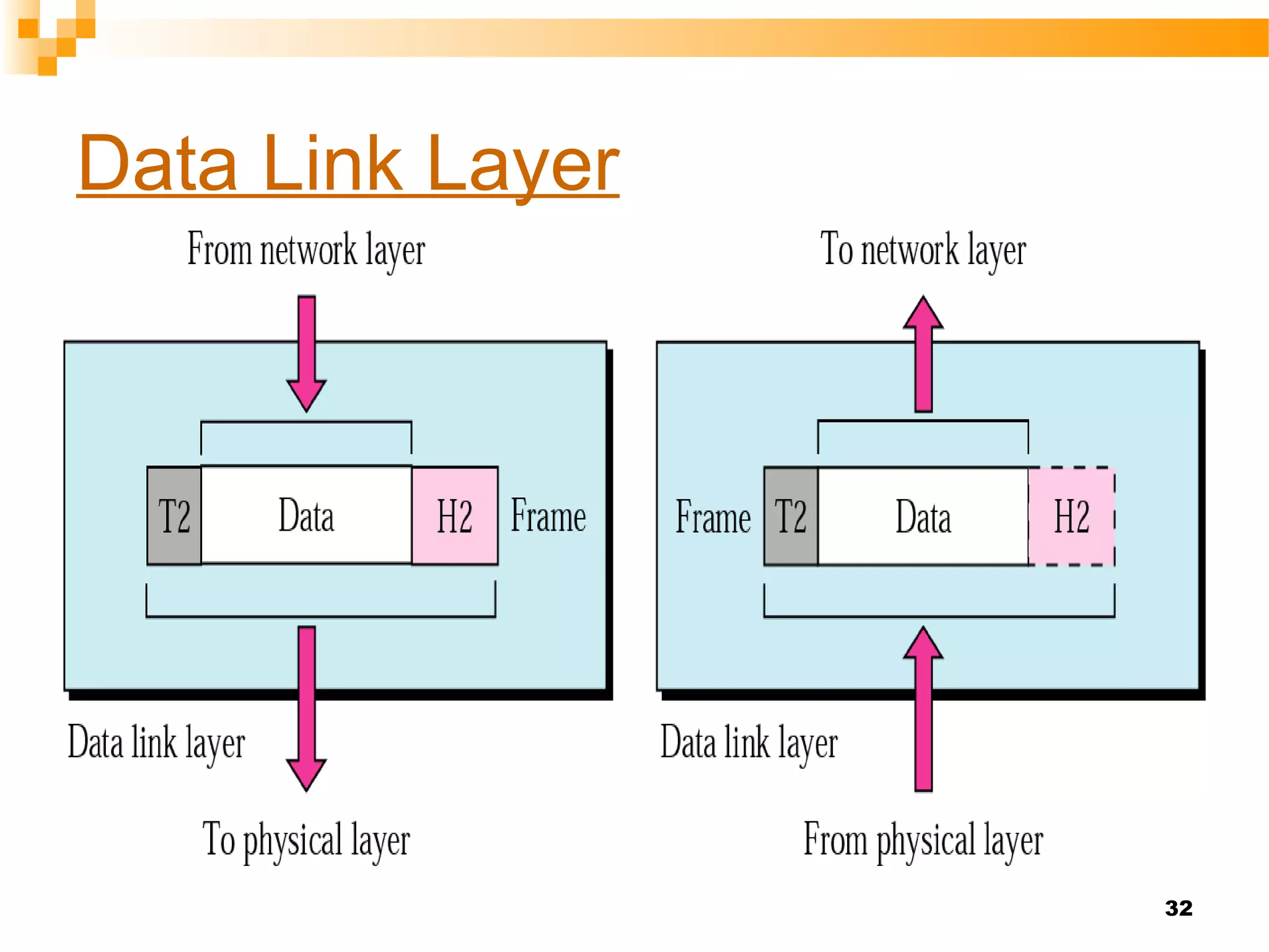
• Framing – divides the stream of bits
received from network layer into
manageable data units called frames.
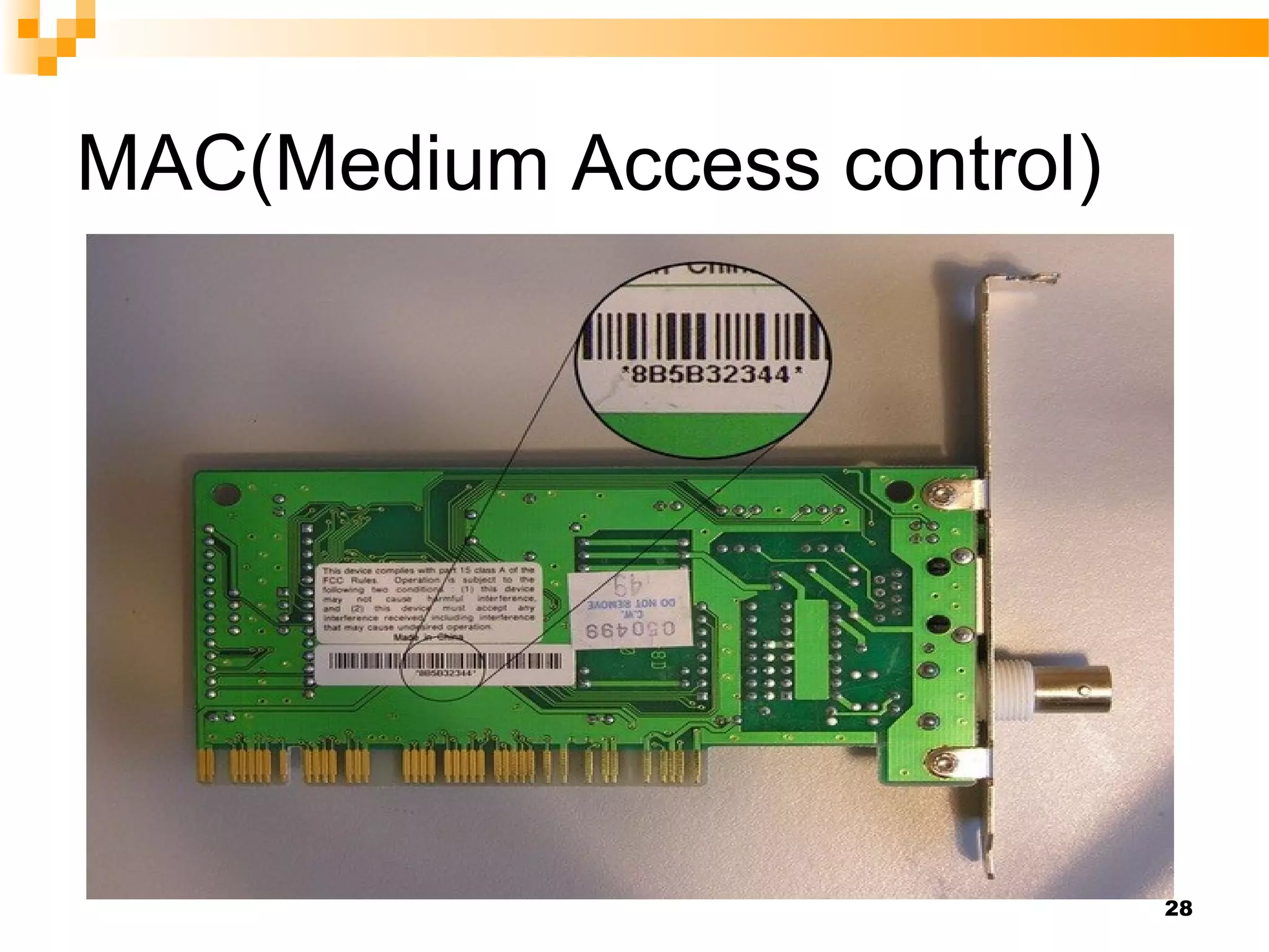
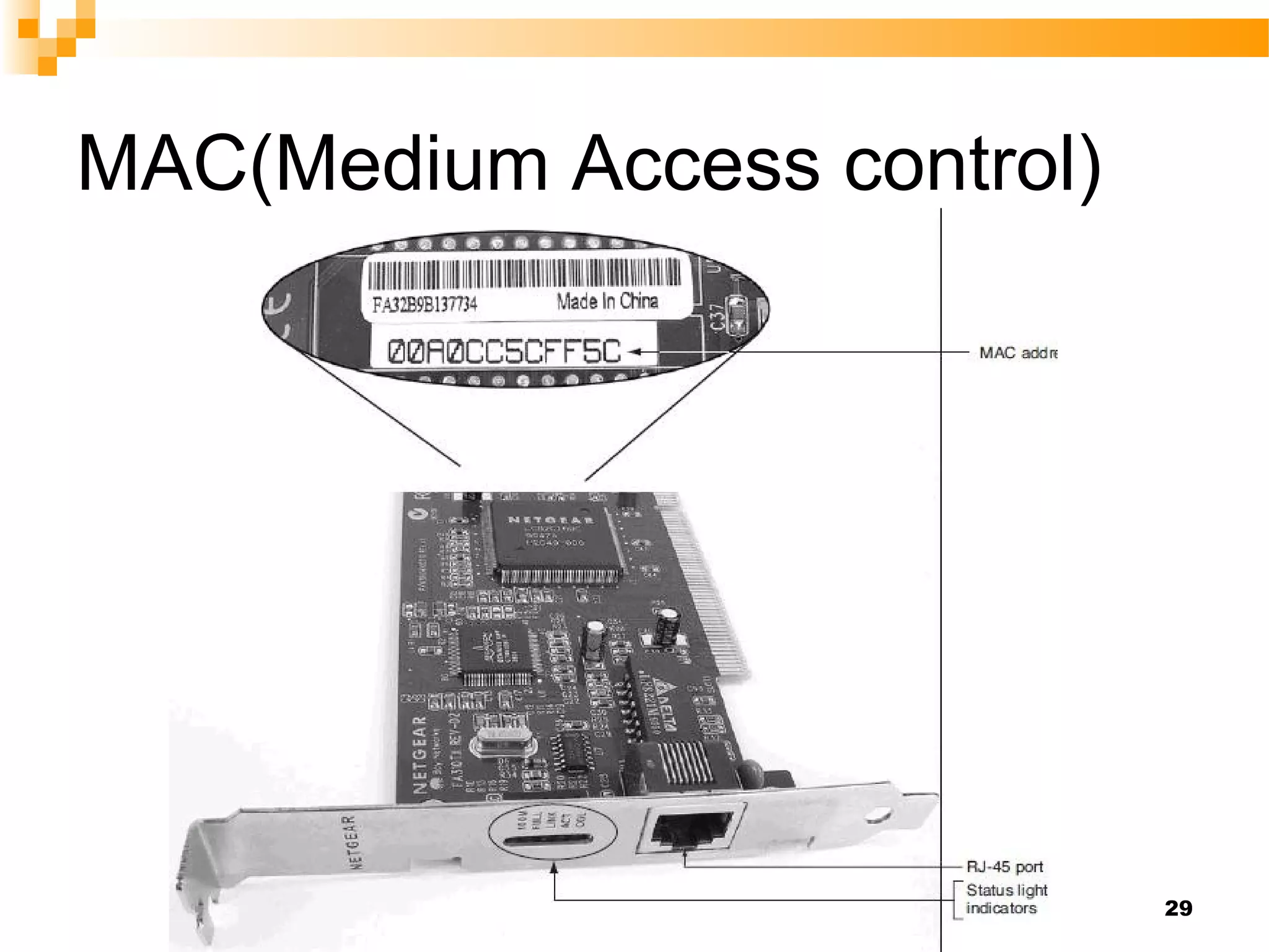
• Physical Addressing – Add a header to the
frame to define the physical address of the
source and the destination
machines(MAC).
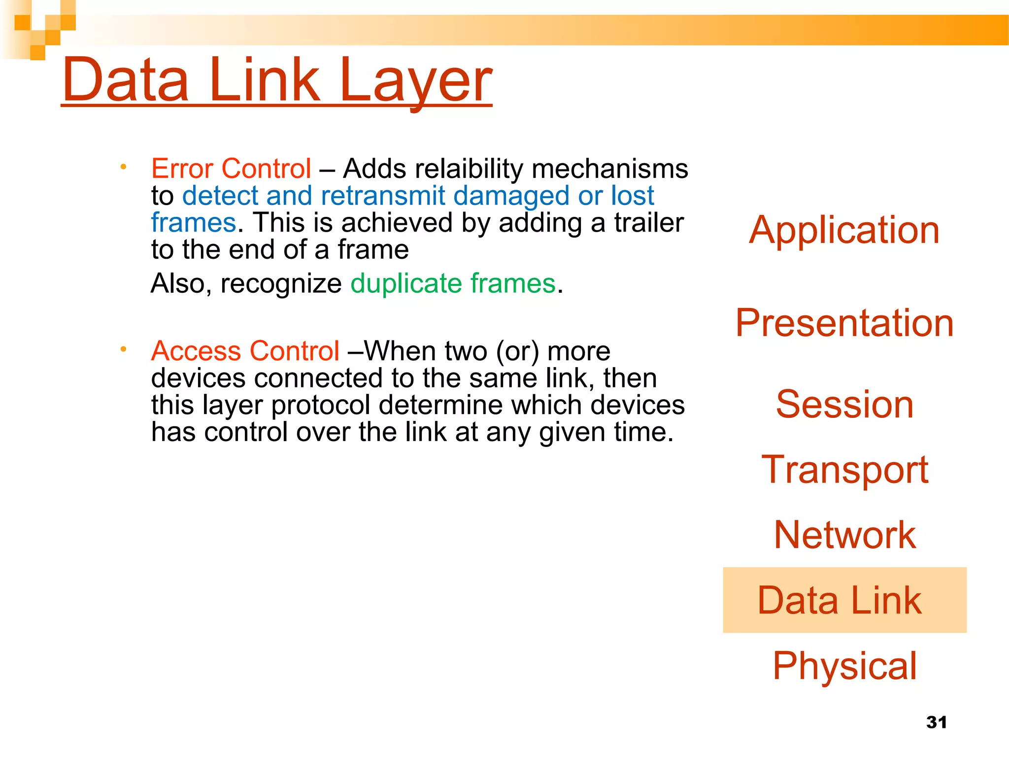
• Flow control – If the receiver is less than
rate of at which data are produced in the
sender.[The flow control mechanism to
avoid overwhelming the receiver]
Application
Presentation
Session
Transport
Network
Data Link
Physical](https://image.slidesharecdn.com/osimodel-siddique-150713072454-lva1-app6892/75/Osi-model-7-Layers-25-2048.jpg)


![34
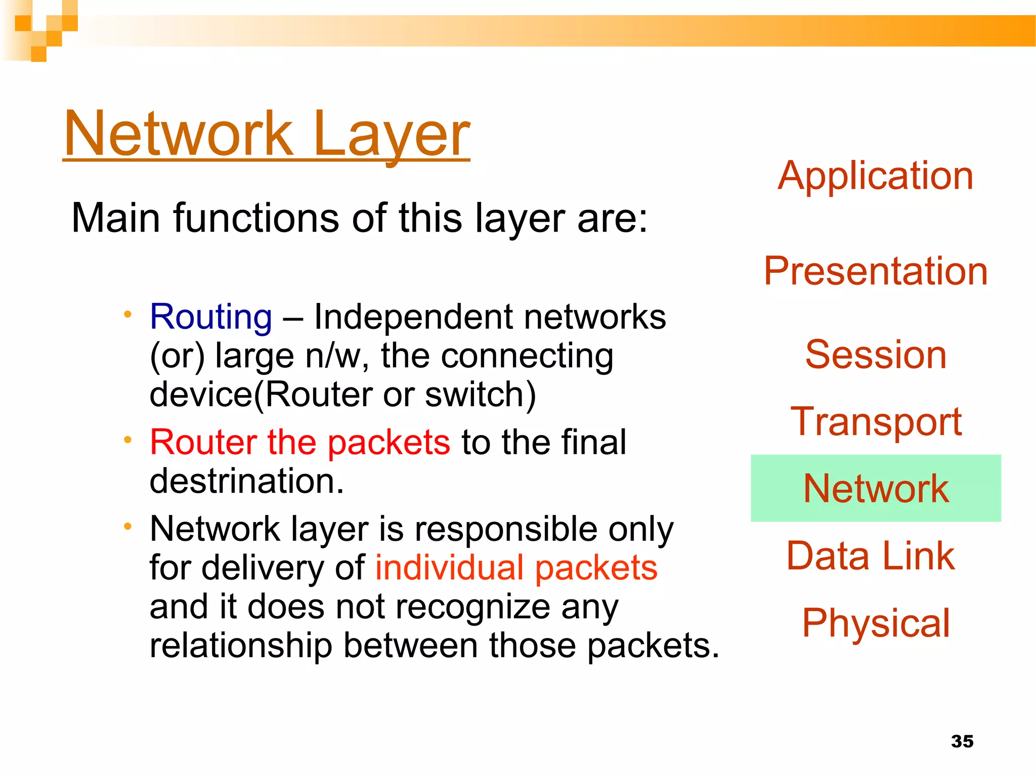
Network Layer
Main functions of this layer are:
• Responsible for delivery of packets
across multiple(sou to des delivery)
networks[Note: if two systems are
connected to the same link there is
no need for a n/w layer]
• Logical Addressing:The physical
addressing implemented by the
data link layer handles the
addressing problem locally(MAC)
• When it passes the boundary the n/w
layer adds a header to the packet(IP)
coming from the upper layer(include
logical address of sender and receiver)
Application
Presentation
Session
Transport
Network
Data Link
Physical](https://image.slidesharecdn.com/osimodel-siddique-150713072454-lva1-app6892/75/Osi-model-7-Layers-33-2048.jpg)

![39
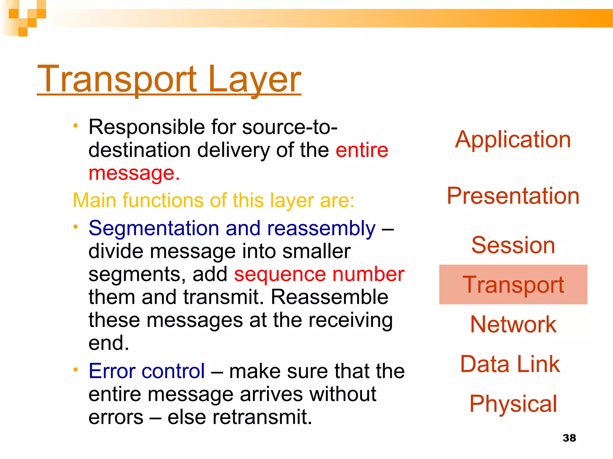
Transport Layer
Service point addressing:
Compuer often run several programs at a same
time.
Sou-to-des not only from one computer to next.
The transport layer header must therefore include
a address called service point address[port
address]
Connection control:
Connectionless- Each segment as a individual
& delivery to the destination.
Connection oriented- Fist establish a
connection with the transport layer at the
destination before the packets send.
After all data packets delivered, then the
connection is terminated.
Application
Presentation
Session
Transport
Network
Data Link
Physical](https://image.slidesharecdn.com/osimodel-siddique-150713072454-lva1-app6892/75/Osi-model-7-Layers-38-2048.jpg)


The document provides an overview of the OSI reference model, which is a framework for data communication among heterogeneous systems. It details the complexities of networks, the importance of protocols for communication, and explains the seven layers of the OSI model, each with specific functions such as error control, addressing, and data flow management. Additionally, it outlines the responsibilities of each layer from the physical layer to the application layer, and emphasizes the need for a structured approach to facilitate data exchange.


![Vibe Coding vs. Spec-Driven Development [Free Meetup]](https://cdn.slidesharecdn.com/ss_thumbnails/vibecodingvsspecdrivendevelopment-251209105622-43f455e7-thumbnail.jpg?width=640&height=640&fit=bounds)


