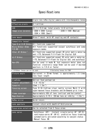
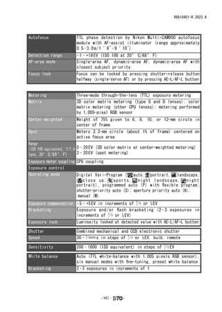
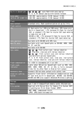
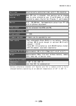
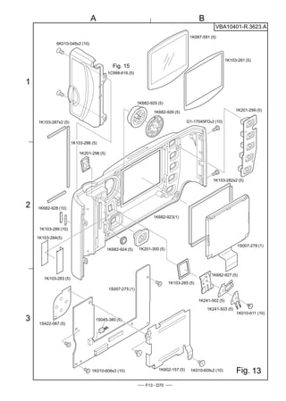
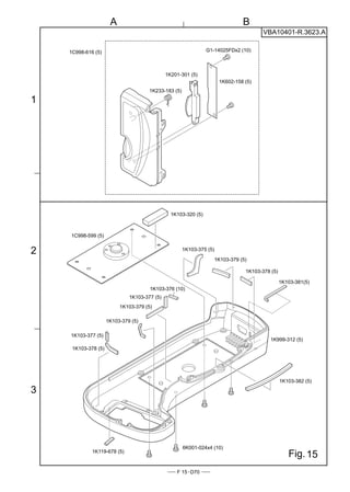
VBA10401-R.3623.A

社外秘                                                   作成承認印           配布許可印


                                      TEMPORARY


                                          VBA10401


                                 REPAIR MANUAL
                                 修  理  指  針


                                          Copyrigh c 2004 by Nikon Corporation.
                                          All Rights Reserved.
                                          無断転載を禁ず !!
Printed in Japan February 2004
VBA10401-R.3623.A


                                     Specifications

Type                       Single-lens reflex digital camera with interchangeable lenses

Effective pixels           6.1 million

CCD                        23.7 × 15.6 mm; total pixels: 6.31 million
Image size (pixels)        • 3008 × 2000 (Large)       • 2240 × 1448 (Medium)
                           • 1504 × 1000 (Small)

Lens mount                 Nikon F mount (with AF coupling and AF contacts)

Compatible lenses*
Type G or D AF Nikkor      All functions supported
Micro Nikkor 85 mm         All functions supported except autofocus and some
f/2.8D                     exposure modes
Other AF Nikkor †          All functions supported except 3D color matrix metering
                           and i-TTL Balanced Fill-Flash for Digital SLR
AI-P Nikkor                All functions supported except 3D color matrix metering,
                           i-TTL Balanced Fill-Flash for Digital SLR, and autofocus
Non-CPU                    Can be used in mode M, but exposure meter does not
                           function; electronic range finder can be used if maximum
                           aperture is f/5.6 or faster
* IX Nikkor lenses can not be used               † Excluding lenses for F3AF

Picture angle              Equivalent in 35-mm format is approximately 1.5 times
                           lens focal length

Viewfinder                 Optical fixed pentaprism
Diopter adjustment         – 1.6 – +0.5 m – 1
Eyepoint                   18 mm ( – 1.0 m – 1)
Focusing screen            Type B BriteView clear matte screen Mark V with
                           superimposed focus brackets and On-Demand grid lines
Frame coverage             Approximately 95% of lens (vertical and horizontal)
Magnification              Approximately 0.75 × (50-mm lens at infinity; – 1.0 m – 1)

Reflex mirror              Quick return

Lens aperture              Instant return with depth-of-field preview

Focus-area selection Can be selected from 5 focus areas

Lens servo                 • Autofocus (AF): Instant single-servo AF (AF-S);
                             continuous-servo AF (AF-C); predictive focus tracking
                             automatically activated according to subject status
                           • Manual focus (M)


                                        - M1 ・      -
VBA10401-R.3623.A


Autofocus              TTL phase detection by Nikon Multi-CAM900 autofocus
                       module with AF-assist illuminator (range approximately
                       0.5 – 3.0 m / 1 ´ 8˝ – 9 ´ 10˝)
Detection range        – 1 – +19 EV (ISO 100 at 20 ° C/68 ° F)
AF-area mode           Single-area AF, dynamic-area AF, dynamic-area AF with
                       closest subject priority
Focus lock             Focus can be locked by pressing shutter-release button
                       halfway (single-servo AF) or by pressing AE-L/AF-L button

Exposure
Metering               Three-mode through-the-lens (TTL) exposure metering
Matrix                 3D color matrix metering (type G and D lenses); color
                       matrix metering (other CPU lenses); metering performed
                       by 1,005-pixel RGB sensor
Center-weighted        Weight   of 75% given to 6, 8, 10, or 12-mm circle in
                       center   of frame
Spot                   Meters   2.3-mm circle (about 1% of frame) centered on
                       active   focus area
Range
(ISO 100 equivalent, f/1.4 0 – 20 EV (3D color matrix or center-weighted metering)
lens, 20 ° C/68 ° F)       3 – 20 EV (spot metering)
Exposure meter coupling CPU coupling
Exposure control
Operating mode          Digital Vari-Program ( auto, portrait, landscape,
                           close up,     sports, night landscape, night
                        portrait), programmed auto (P) with flexible program;
                        shutter-priority auto (S); aperture priority auto (A);
                         manual (M)
Exposure compensation – 5 – +5 EV in increments of 1 3 or 1⁄2 EV
                                                   /
Bracketing            Exposure and / or flash bracketing (2 – 3 exposures in
                      increments of 1 3 or 1⁄2 EV)
                                       /
Exposure lock         Luminosity locked at detected value with AE-L/AF-L button

Shutter                Combined mechanical and CCD electronic shutter
Speed                  30 – 1 8000 s in steps of 1 3 or 1⁄2 EV, bulb, remote
                            /                    /

Sensitivity            200 – 1600 (ISO equivalent) in steps of 1 3 EV
                                                               /

White balance          Auto (TTL white-balance with 1,005 pixels RGB sensor),
                       six manual modes with fine-tuning, preset white balance
Bracketing             2 – 3 exposures in increments of 1


                                   - M2 ・     -
VBA10401-R.3623.A


Built-in Speedlight       • , , , : auto flash with auto pop-up
                          • P, S, A, M: manual pop-up with button release
Guide number              • ISO 200: approximately 15/49 (manual 17/56)
(m / ft at 20 ° C/68 ° F) • ISO 100: approximately 11/36 (manual 12/39)

Flash
Sync contact           X-contact only; flash synchronization at up to 1 5 00 s
                                                                      /
Flash control
TTL                    TTL flash control by 1,005-pixel RGB sensor (CPU lenses only)
                       • Built-in Speedlight: i-TTL balanced fill-flash for digital
                         SLR, or standard i-TTL flash for digital SLR (spot metering
                         or mode dial set to M)
                       • SB-800 or 600: i-TTL balanced fill-flash for digital SLR, or
                         standard i-TTL flash for digital SLR (spot metering)
Auto aperture         Available with SB-800 with CPU lens
Non-TTL auto          Available with such Speedlights as SB-800, 80DX, 28DX,
                      28, 27, and 22s
Range-priority manual Available with SB-800
Sync modes            • , , : front curtain sync, red-eye reduction
                      • : slow sync, slow sync with red-eye reduction
                      • ,      ,   : front curtain sync and red-eye reduction
                        available with optional Speedlights
                      • P, S, A, M: front curtain sync, slow sync, rear-curtain
                        sync, red-eye reduction, slow sync with red-eye reduction
Flash compensation     – 3 – +1 EV in increments of 1 3 or 1⁄2 EV
                                                    /
Flash-ready            Lights when SB-series Speedlight such as 800, 600,
indicator              80DX, 28DX, 50DX, 28, 27, or 22s is fully charged;
                       blinks for 3 s after flash is fired at full output
Accessory shoe         Standard ISO hot-shoe contact with safety lock
Creative Lighting      Supports Flash Color Information Communication and
System                 FV lock with built-in Speedlight, SB-800, and SB-600.
                       SB-800 and 600 also support Advanced Wireless Lighting.

Storage
Media                  Type I and II CompactFlash memory cards; Microdrives
File system            Compliant with Design Rule for Camera File System (DCF)
                       2.0 and Digital Print Order Format (DPOF)
Compression            • NEF (RAW): compressed 12-bit
                       • JPEG: JPEG baseline-compliant


                                   - M3 ・     -
VBA10401-R.3623.A


Self-timer            Electronically controlled timer with 2 – 20 s duration

Depth-of-field        When CPU lens is attached, lens aperture can be stopped
preview               down to value selected by user (A and M modes) or value
                      selected by camera (Digital Vari-Program, P, and S modes)

Monitor               1.8˝, 130,000-dot, low-temperature polysilicon TFT LCD
                      with brightness adjustment

Video output          Can be selected from NTSC and PAL

External interface    USB

Tripod socket         1⁄4˝ (ISO)

Firmware upgrades     Firmware can be upgraded by user

Power source          • One rechargeable Nikon EN-EL3 Li-ion battery; charging
                        voltage (MH-18 quick charger or optional MH-19 multi
                        charger): 7.4 V DC
                      • Three CR2 lithium batteries (with MS-D70 battery holder)
                      • EH-5 AC adapter (available separately)

Dimensions (W × H × D) Approximately 140 × 111 × 78 mm (5.5˝ × 4.4˝ × 3.1˝)

Weight                Approximately 595 g (1 lb 5 oz) without battery, memory
                      card, body cap, or monitor cover

Operating environment
Temperature           0 – 40 ° C (32 – 104 ° F)
Humidity              Less than 85% (no condensation)
• Unless otherwise stated, all figures are for a camera with a fully-
  charged battery operating at an ambient temperature of 20 °C (68 °F).


                                   - M4 ・   -
VBA10401-R.3623.A
Disassembly

                                           � WARNING
                                             警告
                                     Due to an internal high voltage area, take extra care not to get an
                                     内部に高電圧部あり。カバーを外す時は感電に注意すること。
                                     electric shock when detaching covers.
                                     カバーを外した後は、修理指針の指示に従ってメインコンデン
                                     After removing covers, be sure to discharge the main condenser
                                     サーの放電を必ず行うこと。 the repair manuals.
                                     according to the instructions of


Note: ① When disassembling/(re)assembling, be sure to use the conductive mat (J5033) and wrist strap
             (J5033-5) for static protection of electrical parts.
         ② Before disassembling, be sure to remove batteries or AC power wires.
        ③ When disassembling, make sure to memorize the processing state of wires and FPC, screws to be
             fixed and their types, etc.
         ④ Because the low pass filter of the imaging CCD PCB is easily damaged, handle it with enough
             care.


1. Separate Front and Rear bodies

  Bottom Cover


                             #692


                                                        #697

                                                                             #677×6


                                                                                         Open I/F cover


                                                        Bottom cover


                                             - D1 ・              -
VBA10401-R.3623.A
  Rear cover

・Remove the TFT-PCB connection FPC from the connector.
                                                             TFT-PCB connection FPC


・Take out 4 screws (#612).
・Remove the rear cover.
                                                 � WARNING
                                                    警告
                                           Due to an internal high voltage area, take extra care not to get an
                                           内部に高電圧部あり。カバーを外す時は感電に注意すること。
                                           electric shock when detaching the covers.
                                           カバーを外した後は、修理指針の指示に従ってメインコンデン
                                           After removing the covers, be sure to discharge the main
                                           サーの放電を必ず行うこと。
                                           condenser according to the instructions of the repar manuals.


                         #612×4


                                                                                       Rear cover

 Discharge Main condenser

・Discharge the main condenser from its both ends.
                                                                                                       2KΩ/5W


                                                                                                                 Main
                                                                                                                 condenser


                                           - D2 ・                 -
VBA10401-R.3623.A

Disassemble Rear cover


                                                                #605×2          #402


                                                  #435                                                #403
                           #B431                                 #432
                                      #437

           #678×2


                                                                #413

                                                                         #412
           #426×2

                                                                                                                       #421


                   #425            #423


                                                                                                            #404×2


             #443                                                                                                    #1031

                    #444


                                                #408     #416

                                                                                                                       Black
            #409
                                                                         #420
                                                                                                                 Gray A
                                                                                 #417

                                                                                              #418
           #414
                                                                                                     #419       #668
                                    #1071
                                            A
                                                                                       #406


                                      #B2036

                                                                                       #666×2
                            #665×3


                                                   - D3 ・                   -
VBA10401-R.3623.A
 Memory compression PCB

・Remove the USB gasket (#B481) from the memory compression PCB (#B2033).
・Remove the connection FPCs from each connector which are connected from the CF PCB, I/F PCB, main
 PCB, and CCD PCB.
・Remove the ferrite core (#1133) from I/F PCB connection FPC.
・Take out 4 screws (#679) to detach the memory compression PCB (#B2033).


                                                                  #1133


                                     I/F PCB connection FPC            Main PCB connection FPC


                                                                                     #B481


                                                    #B2033


                                                                  CCD PCB connection FPC
             CF PCB connection FPC            #679×4


  CCD-PCB unit


・Remove the CCD-PCB connection harness.


                                                                  CCD-PCB connection harness


                                            - D4 ・            -
VBA10401-R.3623.A
 ・Take out 4 screws (#669) to detach the CCD PCB unit (#B3031).

                                                                   #669×4


                                 #B3031


  DC/DC PCB


・Remove the solders of 10 wires.
・Disconnect 3 connectors.
・Take out 4 screws (#679) to detach DC/DC PCB (#B1030).

                                           Black: Top cover GND
                                               Brown: Front body FPC
                                 Black:                                     #1025
           Gray:
                                 SB PCB                Brown: Main PCB
           SB PCB


      Red:
      SB PCB

   Blue:                                                  #B1030

   Battery
   contact-                                                                                  Black
                                                                                            : I/F PCB
       Orange:                                                                             Red
       Battery                                                                             : I/F PCB
       contact+
                                                                               #1059
                                                       #679×4
                                   #1065


                                           - D5 ・            -
VBA10401-R.3623.A
   Covers

SB pop-up


・Cut the tracing film sheet, etc into the below size of piece. Then insert it into
 the clearance of the top cover pop-up part as shown right, and pop it up by
 sliding the sheet in the direction of the arrow.


                                        Approx.2cm


                   Approx. 4cm


                                                              #611×2        #608
・First, remove the front cover (#B24).


                                                                                            #28

                                                                            #776


                                                                                                    #611×2


            #B26

                                                                        #B24


                                                                                                   #124

                                 #631                                                       #659

                                                                                     #121

                            #684


                                                     - D6 ・       -
VBA10401-R.3623.A
   Top Cover

・Remove the solders of 8 wires.
・Remove FPC#1026 from the connector.

                                                                                                   Black×2
                                                                                                      : Buzzer


  Black                                                                                            Blue×2
  Gray                                                                                             : Main PCB
 White
 Orange
: Lighting unit


                                                                                               #1026


・Take out 6 screws to detach the top cover (#B23). The eyepiece frame (#B271) comes off, too.

                          #B23


                                                                               #613


                                                         # 642                                     #635
   #642


                  # 618              # 618
                          #B271


 External LCD unit                                      # 613×2
                                                                                          Illuminator sw part
                                                                                          Both-sided adhesive tape

・Remove soldering bridges.                                                                on backside of FPC

・Lift up the illuminator sw part
 from the bosses(hub).                                                                               Boss×2
・Take out 2 screws(#613) to detach

   the External LCD (#B2006).


                                                           Soldering bridges          #B2006


                                             - D7 ・         -
VBA10401-R.3623.A
Disassembly of Top cover unit

 SB upper case
 ・Press the pop-up lever A part of the top cover unit so that the built-in SB pops up.
 ・Take out 2 screws (#631).
 ・ Push from beneath the hooking lever of the SB upper case as shown in Fig.1 . Then slide 2 hooks in the
     direction of the arrow to remove the lever.
 ・Deactivate pop-up of the SB lower case unit, and remove the SB upper case.    (Fig.2)


  Pop-up lever A part
                                                                                               SB upper case
                                               Hooking lever


                                      Fig.1


               #631×2


                                                SB lower case unit
                                                                                Fig.2

  Lighting unit PCB

Unsolder Shield wires


                                                                     Red: Lighting unit control PCB
                                                                     White: Lighting unit control PCB

                        Tape (#709)


                                              - D8 ・           -
VBA10401-R.3623.A
Remove Lighting unit control PCB, connection FPC, and Shield wires


                                                              #742
                                                                                  #607

                                                                                   Connection
                                Tapes (#709×2)                                     FPC
                                                              #742


                                                                                             Black
                                                                                             Red
                                                                                             White


                                                                                         Lighting unit control PCB


                                        Shield wires

 SB lower case unit

Remove wire-holding screw/Unsolder wires


                                                       #646


                                                           Yellow: SB pop-up SW
                                                          Green: SB pop-up SW


                                           - D9 ・                -
VBA10401-R.3623.A
Remove Flash-up spring


・Unhook the Flash-up spring
  (#305).

・Take out the screw (#646) and
                                                                     #305
  remove the Flash-up spring
  (#305).


                                                              #646


Remove SB lower case unit


・Pull each wire out of holes.

・Losen 2 hooks of the collar (#308)
  to remove it.

                                                                            SB lower case unit
・Remove the SB case axle (#306).

・Detach the SB lower case unit
  from the top cover.


                                                       #306


                                                #308

                                                                                            #308


                                                                            2 hooks


                                      - D10 ・          -
VBA10401-R.3623.A
 Mode dial PCB unit, Remote control unit, Top cover FPC
Remove attaching screws, soldering bridges
                                                            #642
                                                                   #635


                                                                            #608×2


   Solder: Pop-up solenoid


                                                                                  5 soldering bridges


Detach Mode dial PCB and Remote control unit from Top cover FPC


                                                                          Tape (#733)
                                                                                        Remote control unit


                                                                                     3 soldering bridges
      Black: DC/DC PCB


                                 Top cover FPC


                Both-sided adhesive tape (#464)


                                                                                   Remote control unit
                        Mode dial PCB


                                                  - D11 ・          -
VBA10401-R.3623.A
  Mode dial unit, Release button, Power-supply dial, other small parts
                                                                            Mode dial unit
                                    #142


                          #386
                                                                                   #463

                  #339
                                                                                      #387             #350

                                                                                                #351


                                                            #340
                                                                         #453
                                                                                      #352      Power-supply dial
                   #340                                                  #452
                             #788
                                                     #766            #640
                      #347

               #348                                         #326


                #604×2                     #381

Accessory shoe, Shoe mold unit, Outer LCD window, other small parts


                                                                     Shoe base

                                           #318


                                    Shoe mold unit
       Outer LCD window                                                             #311×2


                 #338


                                                                                                #321

                                                                                               #322


                                                                                             #654×4


                                                            #336×2
                                        #337×2


                                                     - D12 ・         -
VBA10401-R.3623.A
 Preview SW unit


・Remove the solders of 3 wires as shown right, and
  take out the screw (#649) to detach the preview SW
  unit.                                                Yellow

                                                       Green
                           Preview SW unit
                                                        Blue
                                     #649


 Disconnect from Connectors


・Remove the FPC ① , ② , and ③ from each connector in order.                    ③


                                                                        ②

                                                                    ①


Separate Front and Rear bodies


                          #634×4                        Rear body


                                                                        Front body


                                                                                     #646
                                       #699×3


                                                                          #642×3


                                             - D13 ・           -
VBA10401-R.3623.A
2. Front Body
Disconnect Connectors
・Disconnect the FPC ① , ② , ③ , and ④ from each connector in order.


                                                                                         ① #B1008

                                                         ① #B2163
                                                                                           ② #1026


                                                                                     ④ #B1025


 Eyepiece unit
 Metering FPC unit

                                                                    #B2008                      #291×2
・Take out 2 screws (#631) so that the eyepiece unit
 (#B261) with the Metering FPC unit(#B2008)
 attached can be removed.


                              #B2008
                                                                                             #290
                                       #B261


                                                                                      #B261
                                                            Note: The eyepiece unit (#B261) and Metering FPC
                                                            unit (#B2008) is attached with the adhesive. Unless
                     #631×2                                 replacement is necessary, do NOT disassemble them.
                                                            In case of disassembling them or turning the screws
                                                            (#291), AE CCD position adjustment (ref. Assembly
                                                            Chapter) is necessary.


                                               - D14 ・        -
VBA10401-R.3623.A
 Penta unit
                                                       #642×2
                                  #B4

          Adhesive                                        #256


                                                 #642×2
     #255


             #283


             #B277


          #B1021                                        #280


                     #282                          #B279


                                               #1046
          #278                          #739
   #280


    #B279                   #G9


                                                                 #297


                                                                 #G3


                                                                    #284


                                                   - D15 ・              -
VBA10401-R.3623.A
  Main PCB


・Remove the front body FPC (#B1009) from the
 connector.
・Remove the solders and soldering bridges of 7                                                      #B1009
 wires.

                                            Blue×2:
                                            Top cover FPC


                                        Yellow:
                                        A/M change sw
                                                                                            Soldering bridge
                                              Black:
                                              A/M change sw

                                              Brown:DC-DC


                                                                                          Black:AF motor

                                                                                  Red:AF motor


・Take out the screws (#658 and #632) to
 detach the main PCB (#B2001) from the
                                                                           #632
 front plate.
・Remove the connection FPC (#B1004)
 from the connector.                                   #B2001       #658


                                                                                                    #B1004

                                                                                  Connector (backside)


                              Front plate


                                               - D16 ・          -
VBA10401-R.3623.A
  AF sensor unit


                                                                      # 636×3
・Take out 3 screws (#636) with Hexagonal
 wrench, and remove the AF sensor unit
 (#B2163).
・3 springs (#170) come off, too.
                                                                                AF sensor unit
                                                     #728                       #B2163


                                                                     # 170×3


  Shutter unit

                                                            #607
・Remove the solders of 6 wires.
                                                                                         #627
・Take out the screws (#607 and #627) to                            #B31
 detach the shutter unit (#B31).


        Purple           Gray

 Pink            White


                     Brown
                    Orange


                                           - D17 ・            -
VBA10401-R.3623.A
 Inner LCD unit

・Remove the tape (#797).
・Take out 2 screws (#653) to remove the inner LCD unit (#B2010).


                                                                           #B2010


                                                                                     #653×2


                                       #797


 Front body FPC


                                                                   Front body FPC:
                                                                   #1009

                        Black:
              Brown:                    Soldering bridges
                        Fmin
              Fmin


     Red:Mg
              Blue:Mg


                                    Green:SQ

                                Yellow:SQ

                            Orange:SQ

                Soldering bridges


                                                 - D18 ・    -
VBA10401-R.3623.A
    Aperture control unit

Procedure
  
1.Take out 3 screws (#642).

2. Remove the screw (#661), spring (#214) and lever (#254).

3.Lock the mirror-up lever (#203) with the preview locking lever (#222).

4.When the aperture lever is pressed down with finger, the aperture coupling lever (#207) moves in the
   direction of arrow ( ① ).

5.In state of 4., remove the aperture control unit (#B241) by pulling it in the direction indicated by
  arrow ( ② ) while letting the arm (#B241) escape.


                                                               Front body viewed from the bottom
                                                                         Lock #203 with this lever.    
                                                                                 #222                       #203
   #642×3


  #B241                                       Aperture lever


                                                                         #B241

                                                                      Arrow ②
                                                                                               Arrow ①


                                       #254
                                        #214
                                                                                        #207             Arm of #B241
                                        #661


                                               - D19 ・            -
VBA10401-R.3623.A
  AF driving unit
  Lens release button
  Vertical lever                                                 #642
  Horizontal lever                                                                     #115
                                                                  #621

・First, remove the                                                                            #119

  horizontal lever (#193).                                                                                #B116


                        #B172


                                                                                                 #630
             #637×2
                                                                                                           #122

                                                                                                #191


                                                                                          #185

                                                                                                        #195


                                                                                #193
                                                                                                        #630


  Bayonet unit
  A/M-change SW unit            #642
                                                           Soldering bridge of
                                                           #126 and #114
                                  #126             #B125


                                                      #114
                                                                          #B2113
                                              #123
                                                    #607
                                                                                       #645×2


                                                                         #189


                                  #132

                                                                                                        #648×5
                                            #135
                                                      #113×3
                                #131
                                                                                                 #111


                                                                                              #660
                                         - D20 ・             -
VBA10401-R.3623.A
    Aperture lever unit
    F-min Switch unit
    Preview locking lever unit


                                                          #190


                                     #206                        #203


                                                           #209
                                                   #207
                                            #210
                                    #208                                    #205
                                                                         #375
                             #639                                 #212


                                    #375                          #642
                                                                                                                         #222
                                            #213                                                                  #224
                                                                                                #202
                                                                          #134                             #223
                                                                                                         #221
                                                                                   #133
                                                                                             #624      #652


   Mirror unit                                                     #B2231


                                                                                                         #234
・Note that 2 pins (#199) and the pin (#236)
 are attached with the Super X.(C-8008B)


                                               #238
                                                                                      #239

                                                                                                                #199
                                                                                                                   #236


                                                            #199


                                                   - D21 ・                -
VBA10401-R.3623.A
3. Rear body

 IF-PCB
・Take out 2 screws (#610) to remove the IF-PCB from the rear body.

                                                   #610×2
                                    Rear body
                                                                                         IF-PCB


                             Remove the connection FPC
                             (#1061) from the rear body
                             pin.                                     #1061


                                                                                           #1059

                                                                                                         #691
 Bottom Base unit                                                          #75
 Secondary battery unit
                                                                                                   #73


                    #633×2


                                                                                #610×2


                                                                          #66


                                                                           #B103

                                                                 #635×4


                                             - D22 ・         -
VBA10401-R.3623.A
  CF-PCB

・Take out 2 screws (#635) to remove the
 CF-PCB and CF ground plate (#469).
                                                                            CF-PCB


                     #635×2                                                                              #B467


                                                                                              #B1034


                                            Remove FPC by pulling
                 #467
                                            aside in the direction of                #663×2

                                            the arrow.                                    #1064
  Rear body


 Main condenser


                                                  Remove the 2 wires (pink and blue) as       #754×2
    Remove the solders of 2 wires (pink
                                                  described left while setting aside by
    and blue) on the SB-PCB of the front
                                                  passing them through this hole.
    of the rear body.


                               Blue:Main condenser


                              SB-PCB                                                                             #1043


                               Pink:Main condenser


                                              - D23 ・                   -
VBA10401-R.3623.A
 Main-SW FPC 
                                                                                       #B1002
                                                                Soldering bridge

・Remove the soldering bridges on
 the sub-PCB (#B1002) to detach
 the main-SW FPC (#B1011).


                                          #B1011


                                                                                   Both-sided adhesive tape on
                                                                                   backside of FPC

   SB-PCB / Sub-PCB
・Remove the soldering bridges on the sub-PCB (#B1002) and                  Black:SB PCB
 solders of 8 wires.                                                             Red:SB PCB
                                                                                       Blue:SQ motor
                                                                                          Orange:SQ motor

                                                                                                          Brown:
   Yellow:                                                                                                AF assist lamp
   Distinguish SW
                                                                                                          Blue:
                                                                                                          AF assist lamp
  Green:
  Distinguish SW
                       Soldering bridge


                                                                          #664

・Take out the screw (#664) and 2 screws (#684)
                                                                                       #B1041
 so that the sub-PCB (#B1002) and SB-PCB
 (#B1041) are detached. The AF assist lamp             #B1002
 (#B325) comes off, too.                                                               #1065:
                                                                                       Set aside by passing through
                                                                                       the hole of the rear body.
                                                       #684×2
                                                                                            #B325


                                           Rear body


                                            - D24 ・             -
VBA10401-R.3623.A
 Separate SB-PCB from Sub-PCB

・Remove the soldering bridges of Sub-SB            Soldering bridges          #1015
  connection FPC (#1015).
・Remove the connection FPC (#1065) from
 the connector.
                                               #B1002


                                                          Connector
                                                                                                  #1065


   SB PCB


                                                                                                          #642×2
                                                                                      #1015
                                           Soldering bridges


      Black                                                                                                  #B1041


                                                   Red                 #109


                                                     Black
        Red
                                                      Gray


                                                                    #633
  SQ unit
                                          #627×2


                                                                   #B91


                                                                               Rear body bottom


                                          - D25 ・              -
VBA10401-R.3623.A
Main-/Sub- command dial unt


                                                                 #616×2


                                                              #368            Main command dial


                                                              #B367


                                                     #614×2


                                                                             Sub-command dial
                                                                   #B377


Rear body small parts
                                              #643                                         #617×2

                                                       #492
                           #642×2                                                             #146
                                                      #493                 #B1055
                #156                #671×2
                                                                                            #150
                                    #157×2                #491


       #617×2


         #145


           #149


                        #608
                                                                                            #764


                                                                            #762×2
                           #160

                                                            #761


                                                                                #765


                                    - D26 ・           -
VBA10401-R.3623.A
Assembly/Adjustment
                                                  Grease: LEN317A
                                                  Apply to the inner
・NOTE: For undescribed tapes and                  diameter where to
      sponges in"Assembly" section,               put #199 in.
                                                                            #B2231
      refer to"other tapes/sponges" on
      page A44-45 and PARTS LIST.

                                                                                                       #234


1. Front body
  Mirror unit
                                         #238                                 #239

                                                                                                          #199

                                                                                                              #236


                                                          #199


・With being mirror-up as shown right,
  assemble the pins and apply C-8008B
 (Adhesive: Super X) on each pin.


                                           #236


                                                                                            Do NOT allow the adhesive
                                                                                            to be forced out on the head
                                                                                            of #199.
                                                    Adhesive:                 Adhesive:
                                                    C-8008B                    C-8008B


                                                         #119

                                                  #236
                                                              Apply the adhesive only on
                                                              1/4 periphery of the pin on
                                                              mount side.

                                         - A1 ・               -
VBA10401-R.3623.A
Aperture lever unit
F-min SW 
Preview locking lever unit
                                                             #190

Grease:LEN317A
Inner diameter of #203,
                                            #206
#207, and #208                                           #203


                                                      #209
                                              #207
                                      #208 #210
                               #639                                  #205
Grease: MZ-800S                                         #212 #375
Overall of #209
                                                                       #1114
and #210                         #375                        #642          #1115                              #222
                                          #213
                                                                    #134
                                                                        #133                   #202               #224
                                                                                                           #223
                                                                                                          #221
                                                                                                #624 #652
                                                                Brown              Black


 Position for hooking spring
   #375×2

                                            #212

                                                 Black (long)
              #205    Black (short)


                                                                               Assemble Preview locking lever unit
                                           #213
                                                  白                                                            #624
                                                                                                                 624
                                                                                   The edge touches
                                                                                   the front plate when
                                                                                                               #202
                                                                                                                 202              Front
                                                                                   positioning.
                                                                                                                                  plate


                                                                                                              #221
                                                                                                                221
                                                                            #224 position after as-
                                                                            sembling

Grease:LEN317A
                                                                                           Grease:MZ-800S #223
Apply to periphery of shaft                                                                                 223
                                                                                           Apply to overall
                                                                                                          #224                 Grease:
            #212                                                        Longer part comes                   224
                                                                                                                               LEN317A
                                                                        upwards.                   #222                        Apply
                                                                                                   222
                                                                                                                               to inner
                                                                                                                               diameter
    Spring hooking shaft   #205 


                                                       - A2 ・                  -
VBA10401-R.3623.A
 Aperture control unit
1. Turn the sequence white gear of the aperture control unit in the direction indicated by the arrow, and
   position the arm as shown in Fig. ① .
2. Place #248 in center of movement of range, and lock it with #249. (ref. Fig. ①)
3. Lock the lever (#203) with #222. (ref. Fig. ②)
4. While holding the aperture lever down with finger, insert the arm between #207 and #203, then take finger
   off the lever.
                (ref. Fig. ②)
5. Attach 3 screws (#642). (ref. Fig. ③ and ④)
6. Release the locked lever (#222).
   Fig. ①                                                   Fig. ②
             Aperture control unit

                                                                                        Aperture lever


                                      #248


                                       #249


                                                                             Lock

                                                                            Release
                                                                                                          # 203
    Arm
                                                                                          # 222
                                                              #207


    Fig. ③                                                   Fig. ④


                                                                                               # 642×2
                        # 642


                                                                               Direction for
                                                                               positioning


                                              - A3 ・          -
VBA10401-R.3623.A
 AF driving unit
 Preview lever brake             Grease: LEN317A
                                 Apply a little

                                 on sliding surface


  ・After screwing
   the spring (#214),                             # 254
   hook it to #254.


               # 214                              # 661


                        #637×2                                            # 637×2


                                                                 # 214


                                                               # 661


                                 ・ Position #B172 by
                                 following the direction
                                 and screw it.


                                                                                    #B 172


A/M change SW
Lens release button


                                     #642          #B116

                                     #126


                                    #B125


                                       - A4 ・              -
VBA10401-R.3623.A
   Vertical lever


・Assemble by the following order.
#122→#191→#630

* Note: Be careful NOT to bend the
       contact blade of the lens release
       SW.
                                                                                           # 191


                                                                                                   Lens release SW
                                                                                                   comes on the lever.


                                     #630

                                             #122


                                        Grease: LEN317A
                                        Apply to inner diameter
                                        of #122 and #191


   Horizontal lever                                                                            # 630

                                                                      Grease:LEN317A
                                                                                                       # 193


    ・Insert the U-shaped part of
    #193 into the groove of the AF
    driving shaft (#185).


                                                                                                   #185
                                                                                #195
                                                                                Position for
                                                                                hooking spring


                                                 - A5 ・           -
VBA10401-R.3623.A
 Bayonet unit
 AF lens contacts


                                                                                                Grease: LEN317A

                                                                 #114                           #112×3


                                                                                    #B2113

                                                         #123

                                                                #607
                                                                                                         #111


                                                                                   #189


                                            #132                          #642×2                #648×5


                                    #131                               #112×3


                                            #135


                                                                                                         #660


 A/M change SW cover unit


                                                                                                #642       #621


   Yellow
                                                                                                 #115


    Black                                                                                                  #119
                          #126
            Soldering bridge of #126 and #114


                                                - A6 ・           -
VBA10401-R.3623.A
 Height adjustment of AF coupling shaft


① Set the A/M change cam (#122) to
   AF side. (i.e. The AF coupling                                               #625
   shaft (#185) sticks out of the
                                                                                 Adhesive: Screw lock
   bayonet.)

② Adjust the height of the AF coupling
  shaft (#185) with the screw (#625)
  so that it becomes 1.7±0.15mm.

③ After the adjustment, fix the screw
  (#625) with screw lock.


    #185
                          1.7±0.15mm


                       Bayonet mount
                                                                                 #122
                                                                                 A/M change cam


  Height adjustment of Aperture lever

                         ・Measure the height of the aperture lever by using the tool (J18004).
                              Standard: 3.4±0.1mm
                         In case the value is out of standard, make an adjustment by bending the circled part.
                          Be careful NOT to bend the inner part of the lever when adjusting! 


                       3.4±0.1mm


                                        Aperture lever


                                              - A7 ・          -
VBA10401-R.3623.A
 Front body FPC


                     #1009


                                                                         Black:
                                                               Brown:                    Soldering bridges
                                                                         Fmin
                                                               Fmin


                                                      Red:Mg
                                                               Blue:Mg


                                                                                    Green:SQ

                                                                                Yellow:SQ

                                                                             Orange:SQ

                                                                 Soldering bridge


 Inner LCD unit

・Attach the sponge (#295) on the front plate (#22).     ・Attach the inner LCD unit (#B2010)
                                                         with 2 screws (#653).
                                                        ・Attach the tape (#797)

                                                                                      Attachment of #797

                                                         #B2010

                                           #22
                                                                           #653×2

                                                                                                      #797


                    #295


                                            - A8 ・        -
VBA10401-R.3623.A
 Shutter unit

                                                     #607
                                                                                        #627
・Attach the shutter unit (#B31) with the screws                       #B31
 (#607 and #627).


・Make soldering bridges and solder wires.              ・Make an arrangement of wires and attach 2
                                                        pieces of tapes.

                                                       #713
                                                       Wire arrangement
                   Purple           Gray

            Pink            White


Orange Brown


                                                                                #773
                                                                                Protect F-min sw


                                            - A9 ・    -
VBA10401-R.3623.A
   AF sensor unit


                                                                                                    # 636×3
・Attach 3 screws (#636) with Hexagonal
  wrench to screw up but not tight, then give it
  about 1 turn counterclockwise.


                                                               #728


                                                                                                   AF sensor unit
                                                                                                   #B2163


                                                                                                   # 170×3


                                    Horizontal lever (#193)

                                                               AF sensor unit
                                                               #B2163


                                                                                     FPC


・Attach #728 so that the FPC of
 AF sensor unit can be protected.                                                           #728


                                                              Position for attaching #728


                                               - A10 ・                -
VBA10401-R.3623.A
  Main PCB
                                                                    #632

・Connect the FPC (#B1004) to
 the connector of the main FPC                #B2001     #658
 (#B2001), then fix it on the
 front plate unit with 2 screws
 (#658 and #632).


                                                                                              #B1004

                                                                            Connector (backside)


                 Front plate unit


・Connect the front body FPC (#B1009) to
 the connector. Solder each wire and make                                                  #B1009
 solderign bridges for them.


                                     Blue×2:
                              Top cover FPC

                                    Yellow:
                              A/M change SW

                                    Black:                                           Soldering bridges
                                A/M change SW

                                         Brown:
                                        DC-DC PCB


                                                                                  Black:AF motor
                                                                           Red:
                                                                           AF motor


                                               - A11 ・          -
VBA10401-R.3623.A
 Penta unit
                                  #B4                   #642×2


                                                           #256


                                                       Longer hole

                                                 #642×2
      #255


             #283


             #B277


                                                        #280
         #B1021
                                                                                   Longer hole of #283


                     #282                              #B279

                                               #1046
         #278
                                        #739
  #280


     #B279                  #G9


                                                                                Adhesive: C-8008B


                                                                     #297


                                                                     #G3


                                                                        #284


                                                       - A12 ・              -
VBA10401-R.3623.A
   Angle adjustment of Main mirror and sub-mirror

*Tools required:

1.Main mirror 45°Inspection and Adjustment                        2. Sub-mirror 47.75° Inspection and Adjustment

       ① Collimator (J19002)                                                 ① Collimator (J19002)
       ② Reflection mirror (J18362)                                          ② Sub-Mirror 45 deg. inspection tool
       ③ Optical parallel (J18037)                                            (J18324)
       ④ Hexagonal wrench                                                    ③ Hexagonal wrench

                                              Collimator                                                     Collimator

                J18037
                                                                                  J18324
                                                                                                                   Bayonet
                                                    Bayonet


                                             Eccentric pin for
                                             the main mirror

                J18362                                                               Eccentric pin        Sub-mirror
                               Main mirror
                                                                                     for the sub-
                                                                                     mirror


* Standard:                                                                                           Width of line indicates
                                                                                                      deviation.


                         Main mirror          Sub-mirror
   Left-right       ±30’ or less             __  
   deviation                                                     Up-down
   Up-down           ±10’                  +15’ ~ -50'
   deviation
   Distortion        8’or less              8’or less
                                                                 Reference
                                                                 line

* Note:                                                                                         Left-right


・Before and after the adjustment, check the accuracy by moving the main mirror up- and downwards a few
 times.
・Check for the up-down deviation. In case the deviation is out of standard, make an adjustment by turning the
 eccentric pin for the sub-mirror with Hexagonal wrench.
・In case the deviations of up-down and left-right are out of standard, the front plate unit or mirror unit is
 regarded as malfunctioning.
・In case check or adjust only front body, check again after attach the front body to the rear body.


                                                    - A13 ・           -
VBA10401-R.3623.A
 Eyepiece unit
 Metering FPC unit


・Attach the eyepiece unit (#B261) with 2 screws              ・Position the metering FPC unit by following the
 (#631).                                                      direction, then attach it lightly with screws (first
 Attach the metering FPC unit (#B2008) and the                ① , then ② ).
 spring (#290) temporarily with 2 screws (#291).              Give the screws ( ① and ② ) about 3.5 turns
                                                              counterclockwise.

            #B2008                       #291×2
                                                                       Direction for
                                                                       positioning              ①

                                          #290                                                      ②


                       #631×2              #B261


 FPC connections


                                #B1008


                                                        No slack
                                            ④
    #1026         ②
                                            ③


                                   ①
               #1025

                                   #B2163


                                                                                 2 pieces of tape (#709)

                                                                                       Note: Slack here catches the
                                                                                            rear body when it is
                                                                                            attached.


                                                  - A14 ・          -
VBA10401-R.3623.A
2. Rear body

 Rear body small parts
                                                                        #643                                 #617×2
                                                                                      GREEN

                                                                               #492
                                             #642×2                                                              #146
                                                                               #493          #B1055
                              #156                          #671×2                     YELLOW
Pass 2 wires of the
                                                                                                              #150
distinguish SW (yellow/                                     #157×2              #491
green) through this hole
to come out upward.
                                                      RED

                  #617×2                                      BLACK


                    #145


                       #149


                                        #608
                                                                                                               #764


                                                                                               #762×2
                                            #160

                                                                                  #761


                                                                                                      #765


                              Arrange 2 wires of the battery contacts
                              (Orange and Blue) in the side groove of
                              the rear body (as shown by the above
                              dotted line), and cover them with #160.


Orange

                                                         GREEN


Blue                                                        YELLOW


                                                      - A15 ・              -
VBA10401-R.3623.A
    SQ unit


                                                            #633

                                       #627×2


                                                           #B91


                                                                        Bottom of rear body


  Main-/Sub- Command Dial unit


・Arrange 2 wires of the distinguish SW (yellow and green) as follows.


                                                                     #616×2


                                                                     #368           Main command dial


                                                                     #B367


                                                            #614×2


                                                                                  Sub-command dial
                                                                        #B377


                                           - A16 ・            -
VBA10401-R.3623.A
   SB PCB / Sub-PCB

・Assemble the SB PCB (#B1041), sub-SB                      ・Make soldering bridges and solder 5 wires.
 connection FPC (#1015), and SB-PCB holder
 (#109) with 2 screws (#642).


                                                                                       Soldering bridges
                                  #642×2
                 #1015
                                                   Black


                                     #B1041

                                                                                               Red

                                                                                                    Black
     #109
                                                     Red
                                                                                                     Gray


・Connect the connection FPC (#1065) to the connector of           ・Assemble the sub-PCB (#B1002) and the
 the sub-PCB (#B1002). Make soldering bridges of the               SB-PCB (#B1041) with 2 screws (#664
 sub-SB connection FPC (#1015).                                    and #684) into the rear body.


     Soldering bridges    #1015
                                                                               #664


                                                                                       #B1041

                                                               #B1002
                                                                                       #1065:
                                                                                       Pass through the hole of
                                                                                       rear body.

                                                               #684×2
                                                                                           #B325:
                                                                                           Screw #B1002
                                                                                           together with 1 screw.
                                           #1065

              Connector


                                                           Rear body

                                              - A17 ・         -
VBA10401-R.3623.A

                                                                                  Black :SB-PCB
・Make soldering bridges on the sub-PCB (#B1002)
                                                                                     Red:SB-PCB
   and solder 8 wires.
                                                                                        Blue :SQ motor
                                                                                            Orange :SQ motor


                                                                                                           Brown
                                                                                                               :AF assist
     Yellow                                                                                                     illuminator
:Identification
                                                                                                              Blue:AF assist
SW
                                                                                                                   illuminator


          Green
:Identification SW      Soldering bridges                                            Note: Do NOT let 4 wires (black, red, blue,
                                                                                     and orange) be on the right side of the
                                                                                     dotted line by exceeding it.

  Main SW FPC 
                                                                                              #B1002
                                                                    Soldering bridges
・Attach the main SW FPC (#B1011) on the
 sub-PCB (#B1002), and make soldering
 bridges of them.


                                              #B1011


                                                                                            Positioning pin


   Main condenser
Pass 2 wires (pink and blue) through
this hole of the main condenser             #754×2        Direction for
(#1043) to come out to the front side                     positioning
of the rear body.                                                                        Solder 2 wires (pink and blue) on
                                                                                         the front SB PCB of the rear body.


                                                                  #1043


                                                                                                                      Blue
                                                                                                                     :Main
                                                                                                                     condenser
                                                                                                                    SB PCB
                                                                                                                     :Main
                                                       Attach with the polarity                                      condenser
                                                       identification mark
                                                       upwards.                                                      Pink


                                                 - A18 ・                -
VBA10401-R.3623.A
 CF PCB unit


・Attach the CF PCB unit (#B1034) on the CF                                                       #B467
 PCB retainer (#B467) with 2 screws (#663).

・Connect the connection FPC (#1064) to the
 connector of #B1034.


                                             #663×2


                                                                              #B1034


                                                    #1064


・Assemble the CF PCB unit and CF ground                        #635×2
 plate (#469) into rear body with 2 screws
 (#635).                                                                                                  CF PCB unit


                                                                                          Assemble the FPC by
                                                            #469
                                                                                          releasing it in the direction
                                                                                          of the arrow.

                                        Rear body


                                                                       Assemble by pulling the FPC in the direction
                                                                       indicated by the arrow.


                                             - A19 ・               -
VBA10401-R.3623.A
 Bottom base plate
 Secondly battery


・Attach the IF PCB GND plate (#75) with 2 screws
 (#610).

・Attach the secondary battery (#1059) with the
 retaining spring (#73) and spring (#691).

・Attach the bottom PCB (#66) and the DC-DC
 shielding plate (#B103) with 4 screws (#635) and 2                                            #75
 screws (#633).

                                     #73                                              #610×2
                                           #691
                                                 #1059


                                                                                             #1059


                                                                         #75
                                                                                                       #691

                                                                                                 #73


           #633×2


                                                                         # 610×2


                                                                Direction for positioning


                                                                   #66


                                                                          #B103


                                                   #635×4


                                           - A20 ・          -
VBA10401-R.3623.A
 IF PCB unit
・Attach the IF PCB retaining plate (#72) on the IF         ・Attach the IF PCB shielding plate (#76) by making
 PCB (#1035) with 2 screws (#610).                          soldering bridges.
・Solder 2 wires (red and black).                           ・Adhere 2 IF gaskets (#77) to #76.
                                                           ・Atatch the connection FPC (#1061) to the connector.


                                          IF PCB (#1035)


             Red
                                                #72

          Black

                                            #610


                                                                                                 #77×2
                                                                #1061

                                                                                                #76


                                                                        Soldering bridges


・Attach the IF PCB unit to rear body with 2 screws (#610).

                   Rear body


                                                                                              #610×2


                                   The connection FPC (#1061)
                                   comes front side.


                                            - A21 ・               -
VBA10401-R.3623.A
3. Mount Front body on Rear body
 Mount the front body on the rear body
・Do NOT pinch wires and FPCs.
・Attach screws by the following order. #642×3 → #634×4 → #699×3


         #634×4


                                                                                                          #642×3


                                                                                                       Direction for
                                                                                                       positioning to
                                                                                                       attach the front
                                                                                                       plate.
                                       #699×3


                                                                                       #227
                                                                                        #B225          #649
                                                                                                #714


           Arrange FPCs of the inner LCD by putting them into the
           clearance between rear body and eyepiece.


  Preview SW Adjustment


 ① Press the lever (#224) with screw driver, etc                        #B225
    from the bottom of the body so that it touches               #652
    the uppermost part.
                                          Adhesive: Screw lock

 ② In the state of ① , make an adjustment by
   turning the screw #652 so that #227 and #B225
   slightly touch with each other.

 ③ Adhere the screw (#652) with screw lock.                  #227


* Note:
                                                                                #222
Preview switch blade is easily bent, so handle it with care.


                                                  - A22 ・                 -
VBA10401-R.3623.A
  Inspection and Adjustment of Body back

* "0" positioning of the dial gauge


                                                                0" position of D70


                      Surface plate


① Put the tool (J18001-1) on the surface plate, and set the dial gauge to "0".
② Turn the index ring to shift the position by "0.47 mm" from "0" that was set in ① .
  (This position is "0" of D70.)
③ Measure the body back based on "0" reference position of the index ring.


・ Measure 4 parts from the bayonet face to the CCD-PCB
    attaching face.
 
Standard:48.2±0.015mm/ Parallelism: within 0.015mm


・In case it is out of standard, make an adjustment
  by loosening screws that attach the front and rear
  bodies, or by putting the washer(s) on the contact
  surface between the front body and rear body.


                                                                            Parts to be measured


Note: For some bodies, washer(s) are already put on the attaching face of the CCD-PCB.
      There is an indication of the mark in red at the following 2 positions.

  1. Indication: on the camera body side of the CCD-PCB attaching face
   Purpose:To adjust the height of the camera body
       * By adding the measured value to the thickness of washers, check if it is within the standard
           (48.2±0.015mm).
  2. Indication: on the CCD-PCB attaching face
   Purpose:To adjust the height of the CCD-PCB
   * When the CCD PCB is replaced, remove the washers.


                                              - A23 ・          -
VBA10401-R.3623.A


・Arrange the brown wire that was soldered on
 the main PCB (ref. Page A11).


                                           Brown wire


・Arrange each FPC.


                                                                        #1026


                                                                     #1025

                                                                     #1061


・Connect each FPC to the connectors
 in the order of ① , ② , and ③ .


                                                                ②   Arrenge this FPC

                                                            ①       inside of front
                                                                    body FPC
                                                        ③


                                                                     Front body FPC


                                        - A24 ・         -
VBA10401-R.3623.A
 DC-DC PCB 
・Attach the DC-DC PCB (#B1030) with 4 screws (#679).
・Solder 9 wires.
・Connect the connection FPC (#1065), connection FPC (#1025), and secondary battery (#1059) to each
 connector of #B1030.


                                            Brown: Front body FPC
                                  Black:
                                                                                 #1025
           Gray:                                       Brown:Main PCB
                                  SB PCB
           SB PCB


        Red:
        SB PCB

Blue:                                                         #B1030

Battery contact-
                                                                                                      Black
  Orange:                                                                                            :I/F PCB
  Battery contact+
                                                                                                    Red
                                                                                                    :I/F PCB


                                                                                        #1059
                                                           #679×4
                                    #1065


                               Wire arrangement


                                                                        #B1030


                                                  Yellow                Brown
                                       Green
・Solder 7 wires.
                                     Blue


                                                                                 Blue

                                                                                   Yellow

                                                                                         Green


                                            - A25 ・                 -
VBA10401-R.3623.A
  Inspection and adjustment of AE CCD Alignment
・Procedure                                                                                       3rd soldering bridge count-
                                                                                   #B1011        ing from bayonet side
① To prevent short circuit, attach the grip (#B26) with the
   screw (#631).

② Connect 2 parts of the main SW FPC unit (#B1011) with
   jumpers. * 2 parts = Red line as shown right
   i.e. at lower left of the release SW and the 3rd soldering
   bridge counting from the bayonet side.

③ Connect the camera and PC with the communication tool
   (J61205) and MC-31 (J19109).
    (ref. Page A35-A36)

④ Provide power to camera via AC adapter EH-5.
* Note: Be careful of short circuit where there is no cover.
                                                                   Lower left of
⑤ Start up the inspection and adjustment software for
                                                                   release SW                             #631
   D70 (J18361), and select "INSPECTION AND                                                 #B26
   ADJUSTMENT FOR AECCD POSITION" then "CCD
   ALIGNMENT INSPECTION AND ADJUSTMENT".
                                                                                Adhesive: Aron alpha

⑥ By following instructions on PC, make the position ad-
  justment of AECCD by 3 screws.

⑦ Select “CCD SLANT INSPECTION” of the adjustment                                                                X-direction
   software and make an inspection.
                                                                                                                 Adjustable
                                                                                                                 screw
⑧ After the adjustment, fix the AECCD by applying Aron
  alpha (super glue) slightly.                         Y-direction
                                                                Adjustable
⑨ Remove the communication tool (J61205).                       screw

⑩ Remove the jumper wire of ② .

⑪ Take out the screw (#631) and grip (#B26).
                                                              #613×2
 Outer LCD
・Attach the outer LCD (#B2006) with 2
  screws (#613).                                                                                       Illumination SW unit
・ Assemble the illumination SW unit by
  aligning 2 bosses.
                                                                                                                 Boss×2
・Make soldering bridges.


                                                          Soldering bridges
                                                                                             #B2006

                                             - A26 ・                -
VBA10401-R.3623.A
Assembly of Top cover unit
Outer LCD window, Shoe mold unit, Accessory shoe, other small parts


                                         Grease:
                                          MZ-800S                                                           Grease:
                                         Apply to inner                                                     OS-30MF
                                         diameter of hole


              Hole for Exposure compensation button


                                                               Shoe base        Position for applying grease on top cover


                                  #318


  Outer LCD window          Shoe mold unit

                                                                                              #311×2


       #338


                                                                                                           #321


                                                                                                           #322


                                                                                                       #654×4
                                                                               Attach #336 and #337 without leaving
                                                                               any space at A part.


                             #337×2                         #336×2
                                                                                                          A part


                                                   - A27 ・                 -
VBA10401-R.3623.A
Power-supply dial, Release button, Mode dial unit, other small parts

                                                                                                                     #640

                                                                                                                        #452
                                    Adhesive: Crazy glue
                                               at 7 parts
                                                                                                                               #453
                                                                                        Grease:
                                                                                        LEN317A


                                        Mode dial unit
 Mask (#142)
                                                                                                  Backside of Rear cover


                                                                                     Grease: LEN317A


                                                                                          Apply to 2 parts of inner diameter
                 #386
                                                                                          Adhesive:C-8008B

                                                                                                #463
         #339
                                                                                                    #387                  #350


                                                                                                                 #351


                                                              #340
                                                                              #453
                                                                                                   #352       Power-supply dial


          #340                                                              #452
                 #788

          #347                                     #766
                                                                     #640
  #348                                                      #326
                                                                     Adhesive:C-8008B


     #604×2                     #381
                                                                     Backside of Top cover        Front side of Top cover

 #788            Position for attaching #788


     Max 1mm

                                                                                       Grease:LEN317A


                                                                         Grease application of Power-supply dial
    0.5~1.5mm


                                                      - A28 ・          -
VBA10401-R.3623.A
 Top cover FPC, Remote control unit, Mode dial PCB
Attach Mode dial PCB and Remote control unit to Top cover FPC


                                                                          Tape (#733)
                                                                                           Remote control
                                                                                               unit


                                                                                        3 soldering bridges
      Black: DC/DC PCB


                                  Top cover FPC


           Both-sided adhesive tape (#464)


                                                                             Remote control unit
                        Mode dial PCB


Attaching screws, soldering bridges
                                                            #642
                                                                   #635


                                                                            #608×2


                                                                                     Direction for positioning
                                                                                     the mode dial PCB
   Solder: Pop-up solenoid


                                                                                  5 soldering bridges


                                                  - A29 ・          -
VBA10401-R.3623.A
SB lower case unit
Attach SB lower case unit
                                       Grease:MZ-800S

                                                                                    SB lower case unit
・Mount the SB lower case unit on
  the top cover.

・Insert the collar (#308) by
  following the direction as shown
  in Fig.1, and fix it with 2 hooks.

・Insert the SB case axle (#306) in
  the top cover.                                                           Grease:MZ-800S


・Pass each wire throuth the hole of                                                   Grease:MZ-800S
  the collar (#308).


                                                                                            #306


                                                             #306


                                                  #308

  Direction for attaching the collar                                                               #308
  (#308)
                 Fig.1
                                                                                  2 hooks


Attach Flash-up spring


・Attach the Flash-up spring (#305)
  and fix it with the screw (#646).

・Hook the Flash-up spring (#305)
                                                                           #305
  by following the direction of the
  arrow.


                                                                    #646


                                       - A30 ・           -
VBA10401-R.3623.A
Solder wires, wire-atatching screws

                                                           #646


                                                               Yellow: SB pop-up SW
                                                              Green:SB pop-up SW


  Lighting unit PCB

Arrange shield wires, Attach lighting unit control PCB


                                                                  #742
                                                                                        #607

                                                                                           Connection
                                      Tapes (#709×2)                                       FPC
                                                                  #742


                                                                                                   Black
                                                                                                   Red
                                                                                                   White


                                                                                               Lighting unit control PCB


                                            Shield wires
                                                                                   Arrangement of shield wires


                                                                                                 Thinner part


                                                                                                   Thicker part


                                                                                                  Do NOT interfere the
                                                                                                  solenoid.


                                               - A31 ・               -
VBA10401-R.3623.A
Solder Shield wires

                                                                 Red: Lighting unit control PCB
                                                                 White: Lighting unit control PCB

             Tape (#709)


                                                                                    Fiber optics
                                                                                    Note)Both ends of the fi-
                                                                                    ber optics are just pinched
                                                                                    in individual parts, and not
                                                                                    adhered.


 SB upper case

 ・Attach the SB uper case on the SB lower case.(Fig.1)
 ・By pushing the pop-up lever A part of the top cover unit, activate pop-up of the built-in SB.
 ・Confirm that the hooking lever of the SB upper case is hooked to 2 holes.(Fig.2)
 ・Attach 2 screws (#631).


                                       Position for attaching #304

                                                              #304×2


           SB upper case
                                                          Pop-up lever A part                           Hooking lever


                                                                                           Fig.2

                                                #304×2


             #631×2


                                               SB lower case unit
                               Fig.1


                                             - A32 ・                 -
VBA10401-R.3623.A
 Top cover                                                                           AE/AF lock button


・Assemble the eyepiece frame (#B271) by putting the
 diopter adjusting lever at the lowermost position.                                                         #B23


・After pushing outside the AE/AF lock button from the
 inside of the top cover, assemble the top cover (#B23).    #B271
  

・After assembling the top cover, slide the diopter
 adjusting lever to check the movement of the diopter
 adjustment lens.
 Also, check the clicking feeling of the AE/AF lock
 button, too.
                                                                    Diopter adjusting lever


・Attach 6 screws.


                                                                                   #613


                                                           #642                                          #635
    #642


                #618                   #618


・Solder 9 wires.
・Connect FPC (#1026) to the connector.                                                                     Black×2
                                                                                                              :Buzzer


     Black
     Gray
    White                                                                                                  Blue×2
    Orange                                                                                                 :Main PCB
 :SB lighting
 unit
                                                                                                   #1026


                                                                                 Black:Top cover GND


                                              - A33 ・         -
VBA10401-R.3623.A
 Covers


・Assemble the front cover (#B24) at the       ・Pop the SB lighting unit up and attach it
 last stage.                                     with 2 screws (#611).

                                                            #611×2              #608


                                                                                                  #28


                                                                                                           #611×2


             #B26

                                                                           #B24


                                                                                                         #124

                            #631                                                                  #659

                                                                                           #121

                          #684


   Gap adjustment of SB lighting unit

・In case it is out of standard, pop the SB unit up and
 make an adjustment by turning the adjusting dial with
 Hexagonal wrench.

   Standard 0 ~ 0.5mm
           :


                                                                                                        Adjusting dial


                                           - A34 ・               -
VBA10401-R.3623.A
  Accuracy inspection and adjustment (Camera body)

・To connect to PC, as shown below, connect MC-31 (J19109) to the connector of RS232 on PC, then attach
  the communications tool (newly prepared as RP) (J61205) to the connection FPC of camera.
 (Refer to next page for how to connect J61205)


Stabilized power supply
Set value = 9.0V、     0.5Ω 
5.0A
or AC adapter EG-5
                                                                                                         AECCD

                                                                                 Connection FPC          alignment tool
                                                                                                         (J15411)

                             Battery tool
                             J61197

                                                                               J61205


* Note:
When checking “battery check”,
be sure to use the battery tool       Note)
(J61167).                             When connecting to PC by the
                                      communications tool (J61205)
                                      with the memory compression
                                      PCB attached, be sure to
                                      remove the * -marked FPC                                                J19109
                                      from the connector on Page
                                      A41.


                                                                In case of 9 pin type terminal of
                                                                RS232C, connect by using 25
                                                                pins-9 pins converting connector.        To RS232C terminal
                    Flash meter                                 But this is not provided by RJ, so
                    Not prepared as RJ                          use goods on the market.


                                    Shutter tester (EF-8000, etc)


            AF50/1.4D


                                                                                              J18361
                                                                                              D70 inspection and adjustment
                                                                                              software

                                                 - A35 ・               -
VBA10401-R.3623.A

                 How to connect communications tool (J61205)

                                                                                   J61205
① Connect the communications tool (J61205) to MC-31 (J19109).


                                                                                       J19109

② Attach the communications tool temporarily to
   the body A with the screw (6K010-049) which                        B
   is included in package.                                6K010-049
 

③ Loosen the screw (6K010-049)and screw it
  lightly again at the position where the shaft
  C of the body can enter in the hole B of the
                                                                                        C
  communications tool.

 
 Note: Do NOT tighten screw completely.


                                                                             A


                                                                                 Connection
④ Pinch the contact part of the connection FPC with                              FPC
  the communications tool to make a connection.


⑤ Connection is completed.

* Note:
This tool is fixed with just a one screw, so handle the
camera very carefully when the tool is attached.


                                             - A36 ・             -
VBA10401-R.3623.A
                        D70 Inspection and Adjustment Software (J18354)

This inspection and adjustment software runs on Windows.
Install the software by following the below procedure.


The following operating environment is required for installing this program on PC.
         PC            IBM PC/AT compatible
         OS            Windows XP Home Edition, Windows Millennium Edition (Me),
                       Windows 98 Second Edition (SE), Windows 98, Windows 95
        CPU            80486 100MHz ~ Pentium Ⅲ 1.2GHz
   RAM (memory)        32MB or more
        HD             6MB-or-more free disk space is required when installing
  Monitor resolution   800×600 pixels or more
     Interface         Serial Interface
                       ※ USB Interface is not available.


As long as the above hardware requirements are met, any PC such as desktop or laptop, etc is available.


<Notice on start-up>
When starting this program, close all the other applications.
If some other applications are running, this program may not be activated.


<Procedure for installation>
The file (D70SOFT.EXE) of this program is provided via FD or e-mail.
Because this is the self-extracting file, decompress the file before installing, following the next procedure.


1. Create a folder for installation under a name you like and PC drive.
  (e.g.) C:D70


                                              - A37 ・              -
VBA10401-R.3623.A
2. Paste the file (D70SOFT.EXE) in the created folder.


3. Double-click on the pasted file to display the following screen.
    Press the OK button, then decompression starts.


4. When the decompression of file is finished, the file (D70.EXE) is created.


5. The installation is completed.


                                              - A38 ・             -
VBA10401-R.3623.A
<Start-up of Program>
1. Double-click the file (D70.EXE), then the Inspection & Adjustment program for D70 starts.


2. To display in Japanese, select the radio button "JAPANESE" in "LANGUAGE" in the lower right-hand corner
  of the screen ". However, this is not properly viewed in the OS in English version


3. When the "HISTORY" button at the lower-left is pressed, the program version will be displayed.


4. Select each item button according to operation.
 Follow the instructions on the next screen that will be shown after pressing the item button.


5. To finish the program, press the "Close (×)" button in the right-hand corner of the screen or "QUIT.".


                                             - A39 ・             -
VBA10401-R.3623.A
   AE inspection and adjustment
 ① AE CCD alignment inspection and adjustment   (ref. Page A26 for details)
 ② AE accuracy inspection and adjustment
 ③ Aperture accuracy inspection
 ④ Adjustment for battery check level (Use the battery tool (J61197) and stabilized power supply.)
 ⑤ Built-in SB flash inspection and adjustment

〔Tools required〕ref. Page A35.
・Inspection on Battery check indications
 After the battery check adjustment, input each voltage of the below into camera, and check the indications of the
 outer LCD.
 Note: Make an inspection by switching the voltage in the order of ① - ⑦ .


    Outer LCD indication              Set voltage of Stabilized power supply

                                  ① 9.00V                            ⑦ 8.23V±0.1V
                                  
                                  ② 7.98V±0.1V                       ⑥ 8.15V±0.1V


                                  ③ 7.85V±0.1V                       ⑤ 8.05V±0.1V

                      Blink       ④ 7.80V±0.1V

・Built-in SB flash inspection and adjustment
 Set the distance between camera and flash meter to 1 m, and inspect and adjust the light volume of the built-
 in SB. (ref. adjustment software for details)
   AF inspection and adjustment
 Note: When using the adjustment software for the first time, prepare 5 camera of D70 and input the average
        value of the 5 cameras, which was measured when checking the AF accuracy, in "WRITING OF AF ADJ.
        LENS OFFSET VALUE" on the main menu.  
 ① AF accuracy inspection and adjustment (Make all the
   following adjustments.)
 ② YAW, PITCH inspection and adjustment
 ③ LARK adjustment (inc. CCD output adjustment)

〔Tools required〕
 1. When adjusting for all adjustment items
   ref. Page A35.
 2. When inspecting AF accuracy
   ① AF adjustment lens (J18266)
   ② AF adjusting tool (J15259)
   ③ Lens holder for F4 (J15280)
   ④ AF chart(J18344)
   ⑤ Chart illuminator for AF(J15264)
 3. When adjusting YAW, PITCH                                                  Connection FPC

   YAW, PITCH tool(J18230)
 4. When adjusting LARK                                                    * Note: After the adjustment ends, arrange the
   The above tool when inspecting AF accuracy                              connection FPC inside the cover.


                                               - A40 ・                -
VBA10401-R.3623.A
  CCD PCB unit
                                                                     Direction for     #669×4
・Attach the CCD dust-proof seal (#56).                               positioning
・Assemble the CCD PCB unit (#B3031) with             #B3031
 4 screws (#669).                                                                                      A parts
 * Note ①:
 In case there are washers inserted between the
 rear body and the CCD PCB unit, follow the
 instructions of Page A23.
                                                                                                                 #56

* Note ②:
In case spacers are attached at A parts of the CCD
PCB unit, mount the CCD PCB unit without
removing them.
(Red mark is indicated on the attachment surface.)
If there are no indications at A parts, spacers are
unnecessary.


・Attach the CCD PCB connection harness to the connector.


   Memory compression PCB                                              CCD PCB connection harness


・Assemble the memory compression PCB (#B2033) and attach it with 4 screws (#679).
・Attach the USB gasket (#B481) on the memory compression PCB.
・Put the ferrite core (#1133) on I/F PCB connection FPC.
・Connect the connection FPCs, which are connected from CF PCB, I/F PCB, main PCB, and CCD PCB to
 each connector.

                                                               #1133                 * Main PCB connection FPC
                                      I/F PCB connection FPC
                                                                                     When adjusting camera body, re-
                                                                                     move this FPC. ref. Page A35.


                                                                                           #B481
                                                    #B2033


                                        #679×4                    CCD PCB connection FPC
              CF PCB connection FPC


                                                 - A41 ・         -
VBA10401-R.3623.A
 Rear cover
                                                                #605×2               #402


                                                        #435                                      #403
                                       #B431
                                                #437                  #432

                        #678×2


                                                             #413
                                                                       #412
                        #426×2
                                                                                                                  #421
                                       #425

                                              #423


                                                                                                          #1031


                              #443
                                                                             #404×2
                                #444                                                                  Direction for positioning

                                                                  #416
                                                         #408
                       #410                    Adhesive: Crazy glue
                                                                                                               Black
                                                                                                                     A
                              #409                                                                             Gray
                                                                               #420

                                                                                        #417
                                                                                               #418
                                                                                                              #668
                                                                                                      #419
                                               #1071
                              #414                 A
                                                                              Direction for positioning


                                                  #B2036
                                                                             #406       #666×2
                                        #665×3


・Attach the rear cover with 4 screws (#612).


                                                                                                                   Rear cover


              #612×4


                                                       - A42 ・                   -
VBA10401-R.3623.A
・Attach the TFT-PCB connection FPC to the connector.


                                            TFT-PCB connection FPC


  Bottom cover
                                     #692


                                                                 #697
                                                                                    #677×6


                                                                                                 After the bottom cover is attached,
                                                                                                 store the I/F cover.


  ∞ Infinity alignment & adjustment


・Replace the finder screen with the infinity focus check screen (J15410), and use the reference lens (J18010)
 and read the value. In case it is out of standard, increase or decrease washers (#297A or#297B) for
 adjustments.


                      "0" position
    J18010
                                               Standard: ±0.07mm(1 scale = 0.01mm)


                                                Value of J18010               Adjustment
                                               +0.07 ~ -0.07                  Adjustment unnecessary if within standard
                                               +0.08 ~ +0.15                  Decrease washers (#297) (for thinning)
                                               -0.08 ~ -0.15                  Increase washers (#297) (for thickening)
                                               +0.15 or more; -0.15 or less   Check if Front body or Penta box is not
                            Reference
                            line                                              deformed.


                                                   - A43 ・                -
VBA10401-R.3623.A
 Other tapes/ sponges ①


                          - A44 ・   -
VBA10401-R.3623.A
 Other tapes/ sponges ②


                          - A45 ・   -
VBA10401-R.3623.A


       Necessary adjustments on PC when parts are replaced


1. Adjustment software

  Adjustments
          of                 AE CCD       AE        Aperture Adjustment Inspection and       AF      EEPROM
                             position   accuracy    accuracy for battery adjustment for   accuracy     fixed
                                                   inspection check level built-in SB                 values
Parts to be                                                                light volume
replaced


 Shutter unit


 Main FPC                                 ○          ○            ○           ○             ○         ○


 AF sensor unit                                                                             ○

       Top cover or
     SB lower case unit                                                       ○


  DC/DC PCB unit


     Metering FPC unit         ○          ○


 Aperture control PCB unit
                                                     ○


                                          - A46 ・            -
VBA10401-R.3623.A


2. Shooting image adjustment software

  Adjustments
          of            Sensitivity     Gr/Gb        Sensitivity    CCD black     CCD white         TFT         CCD-      TFT       Upgrade
                                      compensation      ratio      point defect   point defect   view angle      PCB    EEPROM        RISC
                                      ADJ (R/B                     compensation compensation                  EEPROM Flashram up    firmware
Parts to be                            filter)                                                                 Flash up
replaced

 Shutter unit


 Main PCB unit


 AF sensor unit


 DC/DC PCB unit


 Metering FPC unit


  Memory compression
         PCB
                                                                                                                ○        ○         *1.
                                                                                                                                         ○

 CF PCB


 I/F PCB


 CCD PCB unit             ○              ○             ○              ○             ○
      TFT PCB or
      TFT monitor
                                                                                                   ○                     ○
                                                                                                                       *2.


*1. Check the type of TFT monitor (NEW or OLD) befor execute " TFT EEPROM Flash up".
   The type is mentioned on the label of TFT monitor. (NEW=262CGX405**** or later )


*2. Execute " TFT EEPROM Flash up" first, then adjust "TFT view angle”.
   Check the type of TFT monitor (NEW or OLD) befor execute " TFT EEPROM Flash up".
   The type is mentioned on the label of TFT monitor. (NEW=262CGX405**** or later )


                                                           - A47 ・                      -
VBA10401-R.3623.A
Shooting Image Adjustment
1. Summary
   When D70 shooting image-related, TFT display-related and listed parts on Page A36 are replaced, be sure to
   make an adjustment by the shooting image adjustment software for D70 (J65048). The details of its function
   and how to use this software are as follows:

2. Adjustment software function
 (1) "Sensitivity" adjustment
 (2) Gr/Gb compensation adjustment (R/B filter)
 (3) "Sensitivity ratio" adjustment
 (4) CCD black point defect compensation
 (5) CCD white point defect compensation
 (6) "Sensitivity" and "Sensitivity ratio" reference values calculation
 (7) "TFT view angle" adjustment
 (8) CCD-PCB EEPROM flashram up
 (9) TFT-PCB EEPROM flashram up
 (10) Reading of RISC version
 ※ When the memory compression PCB is replaced, perform the followings: Flashram up of EEPROM value
     of the CCD-PCB, Flashram up of EEPROM value of the TFT-PCB, and Pixel defect (black and white
     spots) compensation. 
  ※ When the adjustments from (1) to (3) are made, calculate the sensitivity and sensitivity ratio reference
    values of (6) by using the reference body in advance, then perform the adjustments.

3. Hardware requirements
 OS:      Widows98SE,Windows2000,WindowsME,WindowsXP
       Japanese or English OS
 PC: CPU Pentium Ⅱ or more
       Memory 128MB or more
       USB1.1
 Screen size: 1024×768 pixels or more

4. How to set up
 Create any directory in the harddisc of PC, and copy the following files.
 ・D2HIMG.exe・・・・・・・・ Application file
 ・STD.DAT・・・・・・・・・ Standard file
 ・NkdPTP.dll・・・・・・・・・USB-communication application extension file for WinXP
 ・NkdPTPDi.dll・・・・・・・・USB-communication application extension file for Win98SE,Win2K,
                                       WinME
 ※ Be sure to copy the above files in the same directory.

5. Install USB driver
                                                      *
   When this software is used, connect the camera via USB connection and install the USB driver.
   As for Windows2000, WindowsME, Windows98SE, install the USB driver by using NikonCapture.
   However, it is NOT necessary to install it in WindowsXP because the OS incorporates the driver.

  *Before connecting the camera and PC, set USB to "PTP".     (Setup menu → USB → PTP)


                                           - A48 ・            -
VBA10401-R.3623.A
6. How to use
 (1) Perform the D70IMG.exe to start up the main screen. (ref. Fig.1)
 (2) Select ENGLISH / JAPANESE in Language to display the expected menu.(ref. Fig.2)
 (3) Click the desired button to start adjustments.
 ※ When the adjustments from 1. to 3. are made, calculate to get the “Sensitivity” and “Sensitivity ratio”
     reference values of (7) by using the reference body beforehand, then perform the adjustments.
 (4) Follow the instructions to be displayed on screen.
 (5) To complete the procedure, click "QUIT" button or "Close" button at the upper-right corner of the menu.


                                                        Fig.1


                                                          Fig.2

                                            - A49 ・             -
VBA10401-R.3623.A
7. Required equipment and conditions
  ※ AC adapter EH-5 and USB cable (mini B type) UC-E4 are used for all adjustments so they are not
      specified in the list.
                                                                                    ★ New established tool
               Item                           Required equipment                  Setting/Remarks
1 Sensitivity adjustment           ・5100K color viewer            J63070 Equivalent to luminance LV13
                                   (ex-model viewer J63049 is also
                                    available.)
                                   ・Luminance meter BM-3000   
                                                                 J63068
                                   ・Tool lens(to fix aperture) J61185 Aperture F8
                                   ・ND filter                             52 mm,7-step light reduction; Use
                                     (ND8×1+ND4×2)                       the packaged product

2 Gr/Gb compensation               ・5100K color viewer          J63070 Equivalent to luminance LV13
  adjustment (R/B filter)          (ex-model viewer J63049 is also
                                    available.)
                                   ・Luminance meter BM-3000  
                                                                 J63068
                                   ・Tool lens(Fixed aperture)  J61185 Aperture F8
                                   ・SP3 (R filter)  J63087
                                   ・SP1 (B filter)  J63085

3 Sensitivity ratio adjustment     ・5100K color viewer          J63070    Equivalent to luminance LV13
                                   (ex-model viewer J63049 is also
                                    available.)
                                   ・Luminance meter BM-3000  
                                                                 J63068
                                   ・Tool lens(to fix aperture) J61185     Aperture F8; No filter

4 CCD black point defect           ・5100K color viewer          J63070 Equivalent to luminance LV13
  compensation                     (ex-model viewer J63049 is also
                                    available.)
                                   ・Luminance meter BM-3000    
                                                                 J63068
                                   ・Tool lens(to fix aperture) J61185 Aperture F5.6

5 CCD white point defect            Body cap or lens cap                  Environmental temperature approx.
  compensation                                                            20 - 25℃
6 Sensitivity, sensitivity ratio    Same as "Sensitivity adjustment"      No filter when sensitivity ratio
  reference value calculation                                             reference value is calculated.
7 TFT view angle adjustment         None                                  Only for NTSC (unnecessary for
                                                                          PAL)
8 CCD PCB EEPROM flashram None
  up
9 TFT PCB EEPROM flashram None
  up
10 Reading of RISC version          None


                                             - A50 ・           -
VBA10401-R.3623.A
8. Summary

 The summary on each adjustment is as follows:

  (1) Sensitivity adjustment
    Face the camera to the color viewer of LV13 equiv. putting the ND filter (-7 step) between them, and make
    an adjustment by changing the ampgain so that G output can fall in the standard range. Adjust the gain
    value so that the G output average value (Average of Gr/Gb) in the center (300×300 pixels) can reach the
    target output level (approx. 600LSB). The actual adjustment of the gain value is made only under the
    condition of ISO200 and ISO1600, and the medium sensitivity is calculated by the adjustment values of
    these 2 conditions.
    For target output level, use the G output average of sensitivity reference value (ISO200) that was calculated
    by the reference body.

 (2) Gr/Gb compensation adjustment (R/B filter)
     Face the camera to the light-emitting box (color viewer) of LV13 equiv. putting the SP3 (R filter)/SP1 (B
     filter) between them, and make an adjustment so that the output difference in G output average between
     G-B line and G-R line when the whole screen is divided into areas can fall in the standard range.

 (3) Sensitivity ratio adjustment
    Face the camera to the color viewer of LV13 equiv., and make an adjustment so that the R/G, B/G output
    becomes the same as the output ratio of the sensitivity ratio reference value that was calculated by the
    reference body. Adjust only under the condition of ISO200, and use the average value of the center (300
    pixels × 300 pixels).

 (4) CCD black point defect compensation
    When pixels of which the output level is under specified value with LV13 equiv., are detected, rewrite the
    coordinates of the detected pixels as pixel defect compensation data.

 (5) CCD white point defect compensation
    Take a shot on the dark surface. In case the pixel output is found to be beyond the standard value, store the
    detected pixel coordinate as the pixel defect compensation data.

 (6) "Sensitivity" and "Sensitivity ratio" reference values calculation
  ・Sensitivity reference value calculation
      By using the reference body, face the camera to the color viewer of LV13 equiv. putting the ND filter (-7
      step) between them. Then, store the G output average value of the center (300 pixels × 300 pixels) in
      the STD.DAT file as the sensitivity reference value.

  ・Sensitivity ratio reference value calculation
   By using the reference body, face the camera to the color viewer of LV 13 equiv. (without filter). Then,
   calculate the sensitivity ratio reference value GR and GB based on the G/R/B output average of the
   center (300 pixels × 300 pixels), and store them in the STD.DAT file.

     It is necessary to calculate the reference values of "Sensitivity" and "Sensitivity ratio" in order to prevent
     the color temperature fluctuation caused by color viewer's changes over time from affecting the results of
     the shooting image adjustment. By using the reference body, calculate the reference values once in about
     every 3 months, when the fluorescent of the color viewer is replaced.


                                              - A51 ・             -
VBA10401-R.3623.A
 (7) TFT view angle adjustment
   This is for adjusting the display position of TFT. Make an adjustment only for NTSC. (Unnecessary for
   PAL)


 (8) CCD-PCB EEPROM flashram up
    Copy the EEPROM value of the CCD-PCB into the flash memory of the memory compression PCB (AK
    PCB).
    The flashram up is necessary when the memory compression PCB (AK PCB) is replaced. 
    The shooting image-related adjustment values are stored in EEPROM of the CCD-PCB, but the camera
    does not directly access the CCD-PCB EEPROM. It does read out the value, which is stored in the flash
    memory of the AK PCB of the memory compression PCB, and go to RAM to operate. Therefore, to reflect
    the adjustment value, it is necessary to copy the stored value of the CCD-PCB EEPROM into the flash
    memory.
    ※ When the shooting image adjustments of each (1) - (3) are completed, the software automatically
         performs the flashram-up.


 (9) TFT PCB EEPROM flashram up
     Copy the EEPROM value of the TFT PCB, as performed in the above CCD-PCB, into the flash memory.
     It is necessary to flashram up when the TFT PCB is replaced. 
     ※ When the TFT view angle adjustment is completed, the software automatically performs the
          flashram-up.

 (10) Reading of RISC version
     Display the RISC firmware version.


                                          - A52 ・           -
VBA10401-R.3623.A
9. Procedure

9-1. Shooting image adjustment

 ● Calculate the "Sensitivity" and "Sensitivity ratio" reference values by using the reference body beforehand,
   then perform the adjustments. (ref. 9-4.)
 ● For the shooting image adjustment from (1) to (3), perform all of them in this order. The adjustments from
   (1) through (3) are all programmed to be executed in serial order. When (1) is completed, the software
   automatically goes on to the next adjustment.
 ● In case adjustments are interrupted by NG, it is possible to continue the adjustments again after NG. As for
   adjustments that were ended with OK, the storage of adjustment values into EEPROM and the flashram-up
   are completed.

  Note: Adjustments are not possible without resetting "Custom setting" of this camera.
*
    Before the adjustments, record the details of "Custom setting" set by customers if necessary.
 
  Start adjustments
 ・Provide the power for the camera via AC adapter.
 ・Reset "Custom setting".
 ・Set "PTP" mode by Setup menu.
 ・Set the focus mode to M, exposure mode to M, and the exposure compensation to "0" of the camera.
 ・Connect the camera and PC via USB cable.
 ・Set the color viewer luminance to LV13 equiv.

 (1) Sensitivity adjustment
 ・Click "SENSITIVITY ADJUSTMENT" of the main menu on screen.
 ・Attach the tool lens (Aperture F8) and ND filter (ND 8× 1+ ND 4 ×2)to the camera.
 ・Get the camera closest to the center of the illuminated surface of the color viewer.
 ・The adjustment starts. When it is completed, "OK" is displayed.
 ・The software automatically goes on to the next adjustment item.

 (2) CCD Gr/Gb compensation adjustment (R/B filter)
 ・Click "Gr/Gb COMPENSATION ADJ (G FILTER)" on the menu.
 ・Attach the tool lens (Aperture F8) and SP3 (R filter) to the camera.
 ・Get the camera closest to the center of the illuminated surface of the color viewer.
 ・The adjustment starts. When it is completed, the next instructions are displayed.
 ・Attach the tool lens (Aperture F8) and SP1 (B filter) to the camera.
 ・Get the camera closest to the center of the illuminated surface of the color viewer.
 ・The adjustment starts. When it is completed, "OK" is displayed.
 ・The software automatically goes on to the next adjustment.

 (3) Sensitivity ratio adjustment
 ・Click "SENSITIVITY ADJUSTMENT" of the main menu on screen.
 ・Attach the tool lens (Aperture F8) to the camera (without filter).
 ・Get the camera closest to the center of the illuminated surface of the color viewer.
 ・The adjustment starts. When it is completed, "OK" is displayed.


                                            - A53 ・            -
VBA10401-R.3623.A
9-2. Pixel defect (black spots) compensation

 ・Set the color viewer luminance to LV13 equiv.
 ・Provide the power for the camera via AC adapter.
 ・Reset "Custom setting".
 ・Set "PTP" mode by Setup menu.
 ・Set the focus mode to M, exposure mode to M, and the exposure compensation to "0" of the camera.
 ・Connect the camera and PC via USB cable.
 ・Click "CCD BLACK POINT DEFECT COMPENSATION" of the menu on screen.
 ・Attach the tool lens (Aperture F5.6) to the camera (without filter).
 ・Get the camera closest to the center of the illuminated surface of the color viewer.
 ・When the adjustment starts, pixel defects are detected, displaying the number of pixels and addresses.
 ・After confirming the above, click "X" button.
 ・When it is completed, "OK" is displayed.


     * Note: In some cases, NG occurs due to dusts on the CCD.
         Be sure to clean the CCD surface before adjustments.


9-3. Pixel defect (white spots) compensation

 ・Check the environmental temperature (approx. 20-25°C.).
 ・Provide the power for the camera via AC adapter.
 ・Reset "Custom setting".
 ・Set "PTP" mode by Setup menu.
 ・Set the focus mode to M, exposure mode to M, and the exposure compensation to "0" of the camera.
 ・Connect the camera and PC via USB cable.
 ・Click "CCD WHITE POINT DEFECT COMPENSATION" of the menu on screen.
 ・Cap the camera with the body cap or lens cap to shield light from the mount.
 ・When the adjustment starts, pixel defects are detected, displaying the number of pixels and addresses.
 ・After confirming the above, click "X" button.
 ・When it is completed, "OK" is displayed.


                                               - A54 ・        -
VBA10401-R.3623.A
9-4. Sensitivity ratio reference value calculation

 ・Set the color viewer luminance to LV13 equiv.
 ・Provide the power for the camera via AC adapter.
 ・Reset "Custom setting".
 ・Set "PTP" mode by Setup menu.
 ・Set the focus mode to M, exposure mode to M, and the exposure compensation to "0" of the camera.
 ・Connect the camera and PC via USB cable.
 ・Select "SENSITIVITY, RATIO REFERENCE VALUE CALC" of the menu on screen.
 ・The current reference value is displayed on screen.
 ・Click "SENSITIVITY, RATIO REFERENCE VALUE CALC".
 ・The calculation of the sensitivity reference value starts. The message to set conditions is displayed.
 ・Attach the tool lens (Aperture F8) and ND filter (ND 8× 1 + ND 4 ×2)to the camera.
 ・Get the camera closest to the center of the illuminated surface of the color viewer.
 ・The adjustment starts. When it is completed, the software goes on to the sensitivity ratio reference value.
 ・Attach the tool lens (Aperture F8)(Remove ND filter).
 ・The adjustment starts. When it is completed, the sensitivity and sensitivity reference values are stored in
  the standard setting file (STD, DAT).
 ・After this procedure, when the shooting image adjustment is made, the sensitivity and sensitivity ratio that
  were calculated this time are used.

    ※ Calculate the sensitivity and sensitivity ratio reference values once in about every 3 months, and when the
      fluorescent of the color viewer is replaced.


9-4. "TFT view angle" adjustment (only for NTSC; unnecessary for PAL)

 ・Provide the power for the camera via AC adapter.
 ・Set "PTP" mode by Setup menu.
 ・Connect the camera and PC via USB cable.
 ・Click "TFT VIEW ANGLE ADJUSTMENT" of the menu on screen.
 ・When the adjustment starts, a frame appears in the LCD area of camera.
 ・By clicking the "Left", or "Right", or "Up" or "Down" buttons on the window, move the frame from right
  to left or up and down to prevent the frame from running off the edge of the TFT monitor of the camera.
 
9-5. CCD-PCB EEPROM flashram up

 ・Provide the power for the camera via AC adapter.
 ・Set "PTP" mode by Setup menu.
 ・Connect the camera and PC via USB cable.
 ・Click "CCD PCB EEPROM FLASHRAM UP" of the menu on screen.
 ・The adjustment starts. When it is completed, "OK" is displayed.


                                              - A55 ・           -
VBA10401-R.3623.A
9-6. TFT-PCB EEPROM flashram up

 ・Provide the power for the camera via AC adapter.
 ・Set "PTP" mode by Setup menu.
 ・Connect the camera and PC via USB cable.
 ・Click "TFT PCB EEPROM FLASHRAM UP" of the menu on screen.
 ・The adjustment starts. When it is completed, "OK" is displayed.


9-7. Reading of RISC version

 ・Provide the power for the camera via AC adapter.
 ・Set "PTP" mode by Setup menu.
 ・Connect the camera and PC via USB cable.
 ・Click "READING OF RISC VERSION" of the menu on screen.
 ・RISC version is displayed.


10. Procedure for upgrading RISC firmware:
 ・After preparing the CF card, copy the latest version ( XXXX. BIN) into the root directory.
 ・Insert the CF card, and select "FIRMWARE VERSION" from the SETUP menu.
 ・Follow the instructions on screen for version upgrading. It takes approx. 3-4 minutes.
 ・Check the version of firmware by "RISC VERSION" of the image adjustment software.

 Note:
   In case incorrect files are included in the CF card, the details for upgrading are not displayed even
   after selecting "FIRMWARE VERSION" from the SETUP menu.


                                           - A56 ・            -
ポップアップ検出SW
                                                                                                                                                                                                                                                             Pop-up detection SW
                                                                                                                                                                        実体配線図 WIRING                                                                                                                                                   DGND
                                                                                                                                                                                                                                                                                      Yellow                                                      POPDTCT

                                                                                                                                内蔵SB発光部                                                                                                                                                                 Green                                                            PGND
                                    サブ基板                                                                                       Built-in flash tube                                                                                                                                                                         Black
                                    Sub PCB                   SQ-M
                                                                        SQ-M                           AF補助光
                                                                                                       AF-assist
                                                                                             Brown     illuminator
                          Yellow                                                                                                                                                                                                                                                                                                                                    上カバーFPC
                                            電池識別SW
                                            Batt.discrimination                                                                                                                     Pop-up MG                                                                                                                                                                       Top cover FPC
                                            SW                                       OUT-    Blue                                                                                                                                           上カバーFPC
                           Green                                                       A
                                                Vpower                                       OUT-B                                                                                                                                          Top cover FPC
                                     DGND           PGND


                                                                                                                                                                  シャッター基板
                                                                                                                                                                  Shutter PCB                   Pop-up MG                                Pop-up MG

                                                                                                                                                                                                                                                                 S AGN
                                                                                                                                                                                                                                                              SP PDA D
                                                                                                                                                                                                                                                                DK
                                                                                                        Orange                                                                                                                                                                                                                                                          Buzzer
                                                                                                                                                                           SD2       Gray
         電池識別SW
                                                                                                                                                                           SD1       White                                                                                         発光制御
         Battery discrimination SW                                                      Blue
                                                                                                        M                                                                閉SW        Puple                                                                                          Flash control
                                                                                                                                                             Close SW
         メインコンデンサ                                                                                                                                                          開SW      Pink
                                                                                                                                                              Open SW
         Main condenser                                                              Black           SQモーター                                                                COM
                                                                                                     SQ motor
                                                             Red                                                                                                           VO1
                                                                                                                                                                           VO2
                                   Blue
                                                                                                                                                                                                                                                                                                                                              Blue
                                   Pink                           MC-                           PGND               Black
                                                                               Tc+
                                                                                                                   Gray                                                                                                                                                                                                                       Blue
                                                                               Xe-
                                                                                                                        White


- E1 ・
                                                                               Tc-
                                                                               Xe+                                                                                                                                                                                                                                                              Yellow                      OUT-A
                                                                  MC+                                                                                                            Brown                                        前ボディFPC
                                                                                                                                Orange
                                                                                                                                                                   Orange
                                                                                                                                                                                                                                Black                    Front body FPC                                                                                                         DGND
                                            SB基板             VB
                                                                                                       SB基板                                                                                                                                                                                                                                                 Brown
                                                            PGND                                 V     SB PCB
                                            SB PCB                                               B                                                                                                                             Brown
                                                     VMONGND
                                                                                                                                                                                                                                                                                                                                                                    メイン基板


-
                                                    Gray
                                                                                                                                                                                                                                                                                                                                                                    Main PCB
                                                                                                                                                                                                                                                                                                                                                                        AFモーター
                                                                                                                                                                                                                                                                                                                                                                        AF motor


                                                                                                                                                                                                                      Green
                                                              Red


                                                                                                                                                                                                             Yellow
                                            Black
                                                                                                                                                                                                                                                                                                                                                                                       AFモーター


                                                                                                                                                                                                    Orange
                                                                                                                                                                                                                                                                                                                 A/M切替SW                                                               AF motor
                                                  PGND4              PGND6                                                                                     PV-SW1                                                                                         FminiSW
                                              PGND5                                                                                                                                                                                                                                                                                     Black
                                                                                                                                                  Green
                                            DGND                                                                                                                PV-SW2
                                                                                                                                                 Yellow
                                                                                                                                                                                                                              Mup-SW                                                                                                                                M
                                     Vpower                                                                                                                                                                                                                                                                     A/M chenge-over SW
                                                    PGND2                                                                                                                                                                      DGND
                                     PGND3                                                                                                            Blue
                                                      BAT                                                                                                       DGND                                                            SQ-SW                                                                                                              AFモーター
                                                                                     DC/DC基板                                                                                         Red       Blue                                                                                                                                                AF motor
                                                                                                                         PGND
                                                                                                                                     Black
                                                                                     DC/DC PCB              DC-IN
                 Blue                                                                                                                                              Brown                                                                                                                                              SD1
                                                                                                                                                                                                                                                                                                       PGND
                                                                                                                 DC-IN                   Red                                        AP-MG
                                                                                                                                                                                                                                                                                                  開 SW                        SD2
                                                                                                                                                                                                                                                                                                  Open SW
                 Orange                                                                                                                                                                                                                                                                                                                          DGND
                                                                                                                                                                                                                                                                                          PGND


                                                                                                                                                                                                                                                                                   OUT3

                                                                                                                                                                                           1:Black:GND                                                                      OUT4                                                                 FminiSW

                                                                                                                                    IF基板                                                                                                                                                                                               SQSW
                                                                                                                                                                                                                                        TFTモニタ
                                                                                                                                                                                           2:Gray:VCC                                   TFT Monitor                                                                            MUPSW
                                                                                                                                    IF PCB
                                                                                                                                                  -          +                                                                                                      PVSW2                            APMG2
                                                                                                                                                                                                                                        +            -                                                                  DGND
                                                                                                                                                                                                                                                                                                              APMG1
                                            MC 基板 MC PCB                                                                                                                                                                                                                                  PVSW1
                                                                                                                                                                                                                                               TFT                          DGND


         電池接点                                                                                                                                                                            TFT基板
         Battery contact                                                                                                                                                                 TFT PCB
                                                                                                                                                                                                                                                                                                                                                                                                  VBA10401-R.3623.A
VBA10401-R.3623.A


               工 具・TOOLS                           ★:新規設定工具・NEW TOOL


    工具番号         名 称                                備 考
    Tool No.     Name of tool                       Others

    J61205      カメラ通信工具
★               Camera communication tool


    J15411      AE CCD 位置出し工具

★               AE CCD positioning tool


    J15410      無限合致調整用スクリーン
                Infinity focus adjustment screen
★

    J18362      反射ミラー

★               Reflection mirror


    J18361      カメラ部点検、調整ソフト

★               Inspection and adjustment
                software for CAMERA
    J65058      撮像部点検、調整ソフト

★               Inspection and adjustment
                software for IMAGING
    J18344      AFチャート                             FOR D100
                AF adjusting chart


    J18230      YAW、PITCH工具                        FOR F5,F100,F90,F90X
                Yaw,Pitch adjustment tool


    J15259      AF調整工具台
                AF adjusting tool


    J15280      Zレンズ用支持ホルダー
                Lens holder


    J15264      高周波タイプ蛍光灯器具
                Illumination box for AF
                adjustment
    J18266      AF調整用Zレンズ(1m用)                     FOR F5,F100
                Z adjustment lens (For 1m)


                      - T1 ・          -
VBA10401-R.3623.A
                                              ★:新規設定工具・NEW TOOL
工具番号        名 称                                備 考
Tool No.    Name of tool                       Others
J19109     MC-31
           MC-31    


J19123     シャッタ-試験機 EF- 1(CE) 共立電機製
           Shutter Tester EF-1(CE)            KYORITSU ELECTRIC
                                              EF -8000 usable

J19002     縦型焦点面検査機 LT-500S                   J 19110 usable
           Back focus collimator LT-500S      J 19110 でも代用可


J18324     サブミラー45°出し工具                       FOR F5,F100,F80,F65
           Sub mirror angle adjustment tool


J18037     オプチカルパラレル
           Optical parallel


J18004     絞りレバー高さ点検工具
           Aperture lever positioning gauge


J19004-1   インジケータ及びスタンド
           (ボディバック台、ゲージ)
           Dial indicator and Stand

J18001-1   ボディバック出し工具
           Body back focus gauge


J19001     無限合致コリメーター F=600mm
           Collimator F=600mm


J18010     無限大合致基準レンズ 50/1.8
           Infinity Standeard Lens 50/1.8


J18267     AF50/1.4D
           Lens AF50/1.4D


J15274     J15264 用チャートボード
           Chart board for J15264


                 - T2 ・         -
VBA10401-R.3623.A
                                          ★:新規設定工具・NEW TOOL

 工具番号        名 称                                   備 考
 Tool No.    Name of tool                          Others


J61197      電池工具                                  FOR D100
            Battery tool


J61185      撮像関係調整用レンズ                            FOR D1,D2H
            D1 Standard lens


J18191      NDフィルタ-8X                             FOR D2H
            ND filter 8X


J18358      NDフィルタ- 4 X                           2枚使用
            ND filter 4X                          It uses by two
                                                  pieces

J63070      カラービュワー                               J63049 でも代用可
            Color Viewer                          J63049 usable


J63068      輝度計(BM-3000)
            Luminance Meter BM-3000


J63085      フィルター SP1 (75X75MM)                   FOR D2H
            Filter SP1 (75X75MM)


J63087      フィルター SP3 (75X75MM)                   FOR D2H
            Filter SP3 (75X75MM)


                           - T3 ・     -
VBA10401-R.3623.A
                                            ★:新規設定工具・NEW TOOL
 工具番号        名 称                             備 考
 Tool No.    Name of tool                    Others

OS-30MF     ドライサ-フ OS-30MF
            DRY SURF OS-30MF(OIL BARRIER)


LEN317A     グリース LEN317A
            Grease LEN317A

EDB0011     ネシ゛ロック(赤)1401C
            Screw lock 1401C


C-8008B     セメダイン 8008(黒)
            Cemedain 8008(BLACK)


MZ-800S     ドライサ-フ MZ-800S
            DRY SURF MZ-800S


            アロンアルファ                         汎用品
            Crazy glue                      RJ is Not available


            フラッシュメーター                       汎用品
            Flash Meter                     RJ is Not available

            デジタルマルチメータ                      汎用品
            Digital meter                   RJ is Not available

            ACアダプター EH-5                    製品転用
            AC adapter EH-5                 RJ is Not available


            USBケーブル UC-E4                   製品転用
            USB cable UC-E4                 RJ is Not available

            パーソナルコンピュータ                     汎用品
            Personal computer               RJ is Not available

            安定化電源(10 V 5 A )                汎用品
            Power supply(10V 5A)            RJ is Not available


            へクスキー(φ 1.5mm)                  汎用品
            HEX.KEY WRENCH ( φ 1.5mm)       RJ is Not available


                 - T4 ・         -
�                                                       �
                                                                                                   �����������������

                                                           �����������������
                                                                                       ��������������


                �������������
                                                                                                               �������������
                        �����������������
                                                                                               �������������
�

                                                                                             �������������


                                                                                             �������������
                                                                                                                 ����������
                         ��������������                                                                          �������������

                                ��������������
                                                                                                                 △
                                                                                                                 ������������
       �������������


                                                                                                                 △
                                                                                                                 ������������
                                                                                          ���������
                                                                                          ����������
                                                                                                               �������������


                                                                                             �������������


�
                                                                                                      ����������
     �������������
                                                                                                      �������
                                                                              ��������������


                                                                    �������������
                                                   ���������������
                                                                                                                 �������������
                                                                      �������������
                                        ��������������                �������������                            �����������
                                                                                                               �����������
                                                                                                      �������������
                                                   �������
    �����������������                                                                            �������������
                                                 �������������
                       ��������������

          △ �������������
          �
             �������������
�
                                                                                      ����������������


                                                                              ���������������


                                                                            ��������������

                �������������
                                                                 ���������������                               ���� ��
    △x1
    �     Feb 19,2004
    △x2   Feb 6,2004                                         ��� ���
�                                                          �
                                                                                                   �����������������
               �                                                                      �������������
             ����������������


                                                                                                           �������������
                                              �������
                                           �������������

�

                                                           �������������

                                                                   �������������                                �������������

    ���������������                                                                  �����������������


                       ��������� ���
                                   �


                           �������������


                                                                                                  ���������������


�   ��������������

                                                                   ������������

     ��������������

    ������������
                                                                                                                 �������������
                                           �������������   �������������


                                                                                                 �������������
       �������������
                                                                           �������������
                                           �������������

                                                                                           �������������

                                                                                               �������������
                                                                                                                ��������� �����
�    �������������
                                   �������������


                                 ����������������                    �������������    ����������������          ���� ��
                                                               ��� ���
�                                                        �
                                                                                       �����������������

    �������������                                               �����������������


                                              �������������
                                                                      �������������
                                      �������������

�


                                                �������������


    �������������


�                                                     �������������

                                                                   �������������

                                                                                �������������

                                                                                                �������������
                                      ��������������
                              �������������
                          �������������

                     �������������

    �������������
                                                                                          �������������
     �������������


                                                                                                �������������

�


                                                      ����������������
             �������������
                                                                                                   ���� ��
                                                  ���� ���

Nikon D70 service manual

  • 1.
    VBA10401-R.3623.A 社外秘 作成承認印 配布許可印 TEMPORARY VBA10401 REPAIR MANUAL 修  理  指  針 Copyrigh c 2004 by Nikon Corporation. All Rights Reserved. 無断転載を禁ず !! Printed in Japan February 2004
  • 2.
    VBA10401-R.3623.A Specifications Type Single-lens reflex digital camera with interchangeable lenses Effective pixels 6.1 million CCD 23.7 × 15.6 mm; total pixels: 6.31 million Image size (pixels) • 3008 × 2000 (Large) • 2240 × 1448 (Medium) • 1504 × 1000 (Small) Lens mount Nikon F mount (with AF coupling and AF contacts) Compatible lenses* Type G or D AF Nikkor All functions supported Micro Nikkor 85 mm All functions supported except autofocus and some f/2.8D exposure modes Other AF Nikkor † All functions supported except 3D color matrix metering and i-TTL Balanced Fill-Flash for Digital SLR AI-P Nikkor All functions supported except 3D color matrix metering, i-TTL Balanced Fill-Flash for Digital SLR, and autofocus Non-CPU Can be used in mode M, but exposure meter does not function; electronic range finder can be used if maximum aperture is f/5.6 or faster * IX Nikkor lenses can not be used † Excluding lenses for F3AF Picture angle Equivalent in 35-mm format is approximately 1.5 times lens focal length Viewfinder Optical fixed pentaprism Diopter adjustment – 1.6 – +0.5 m – 1 Eyepoint 18 mm ( – 1.0 m – 1) Focusing screen Type B BriteView clear matte screen Mark V with superimposed focus brackets and On-Demand grid lines Frame coverage Approximately 95% of lens (vertical and horizontal) Magnification Approximately 0.75 × (50-mm lens at infinity; – 1.0 m – 1) Reflex mirror Quick return Lens aperture Instant return with depth-of-field preview Focus-area selection Can be selected from 5 focus areas Lens servo • Autofocus (AF): Instant single-servo AF (AF-S); continuous-servo AF (AF-C); predictive focus tracking automatically activated according to subject status • Manual focus (M) - M1 ・ -
  • 3.
    VBA10401-R.3623.A Autofocus TTL phase detection by Nikon Multi-CAM900 autofocus module with AF-assist illuminator (range approximately 0.5 – 3.0 m / 1 ´ 8˝ – 9 ´ 10˝) Detection range – 1 – +19 EV (ISO 100 at 20 ° C/68 ° F) AF-area mode Single-area AF, dynamic-area AF, dynamic-area AF with closest subject priority Focus lock Focus can be locked by pressing shutter-release button halfway (single-servo AF) or by pressing AE-L/AF-L button Exposure Metering Three-mode through-the-lens (TTL) exposure metering Matrix 3D color matrix metering (type G and D lenses); color matrix metering (other CPU lenses); metering performed by 1,005-pixel RGB sensor Center-weighted Weight of 75% given to 6, 8, 10, or 12-mm circle in center of frame Spot Meters 2.3-mm circle (about 1% of frame) centered on active focus area Range (ISO 100 equivalent, f/1.4 0 – 20 EV (3D color matrix or center-weighted metering) lens, 20 ° C/68 ° F) 3 – 20 EV (spot metering) Exposure meter coupling CPU coupling Exposure control Operating mode Digital Vari-Program ( auto, portrait, landscape, close up, sports, night landscape, night portrait), programmed auto (P) with flexible program; shutter-priority auto (S); aperture priority auto (A); manual (M) Exposure compensation – 5 – +5 EV in increments of 1 3 or 1⁄2 EV / Bracketing Exposure and / or flash bracketing (2 – 3 exposures in increments of 1 3 or 1⁄2 EV) / Exposure lock Luminosity locked at detected value with AE-L/AF-L button Shutter Combined mechanical and CCD electronic shutter Speed 30 – 1 8000 s in steps of 1 3 or 1⁄2 EV, bulb, remote / / Sensitivity 200 – 1600 (ISO equivalent) in steps of 1 3 EV / White balance Auto (TTL white-balance with 1,005 pixels RGB sensor), six manual modes with fine-tuning, preset white balance Bracketing 2 – 3 exposures in increments of 1 - M2 ・ -
  • 4.
    VBA10401-R.3623.A Built-in Speedlight • , , , : auto flash with auto pop-up • P, S, A, M: manual pop-up with button release Guide number • ISO 200: approximately 15/49 (manual 17/56) (m / ft at 20 ° C/68 ° F) • ISO 100: approximately 11/36 (manual 12/39) Flash Sync contact X-contact only; flash synchronization at up to 1 5 00 s / Flash control TTL TTL flash control by 1,005-pixel RGB sensor (CPU lenses only) • Built-in Speedlight: i-TTL balanced fill-flash for digital SLR, or standard i-TTL flash for digital SLR (spot metering or mode dial set to M) • SB-800 or 600: i-TTL balanced fill-flash for digital SLR, or standard i-TTL flash for digital SLR (spot metering) Auto aperture Available with SB-800 with CPU lens Non-TTL auto Available with such Speedlights as SB-800, 80DX, 28DX, 28, 27, and 22s Range-priority manual Available with SB-800 Sync modes • , , : front curtain sync, red-eye reduction • : slow sync, slow sync with red-eye reduction • , , : front curtain sync and red-eye reduction available with optional Speedlights • P, S, A, M: front curtain sync, slow sync, rear-curtain sync, red-eye reduction, slow sync with red-eye reduction Flash compensation – 3 – +1 EV in increments of 1 3 or 1⁄2 EV / Flash-ready Lights when SB-series Speedlight such as 800, 600, indicator 80DX, 28DX, 50DX, 28, 27, or 22s is fully charged; blinks for 3 s after flash is fired at full output Accessory shoe Standard ISO hot-shoe contact with safety lock Creative Lighting Supports Flash Color Information Communication and System FV lock with built-in Speedlight, SB-800, and SB-600. SB-800 and 600 also support Advanced Wireless Lighting. Storage Media Type I and II CompactFlash memory cards; Microdrives File system Compliant with Design Rule for Camera File System (DCF) 2.0 and Digital Print Order Format (DPOF) Compression • NEF (RAW): compressed 12-bit • JPEG: JPEG baseline-compliant - M3 ・ -
  • 5.
    VBA10401-R.3623.A Self-timer Electronically controlled timer with 2 – 20 s duration Depth-of-field When CPU lens is attached, lens aperture can be stopped preview down to value selected by user (A and M modes) or value selected by camera (Digital Vari-Program, P, and S modes) Monitor 1.8˝, 130,000-dot, low-temperature polysilicon TFT LCD with brightness adjustment Video output Can be selected from NTSC and PAL External interface USB Tripod socket 1⁄4˝ (ISO) Firmware upgrades Firmware can be upgraded by user Power source • One rechargeable Nikon EN-EL3 Li-ion battery; charging voltage (MH-18 quick charger or optional MH-19 multi charger): 7.4 V DC • Three CR2 lithium batteries (with MS-D70 battery holder) • EH-5 AC adapter (available separately) Dimensions (W × H × D) Approximately 140 × 111 × 78 mm (5.5˝ × 4.4˝ × 3.1˝) Weight Approximately 595 g (1 lb 5 oz) without battery, memory card, body cap, or monitor cover Operating environment Temperature 0 – 40 ° C (32 – 104 ° F) Humidity Less than 85% (no condensation) • Unless otherwise stated, all figures are for a camera with a fully- charged battery operating at an ambient temperature of 20 °C (68 °F). - M4 ・ -
  • 6.
    VBA10401-R.3623.A Disassembly � WARNING 警告 Due to an internal high voltage area, take extra care not to get an 内部に高電圧部あり。カバーを外す時は感電に注意すること。 electric shock when detaching covers. カバーを外した後は、修理指針の指示に従ってメインコンデン After removing covers, be sure to discharge the main condenser サーの放電を必ず行うこと。 the repair manuals. according to the instructions of Note: ① When disassembling/(re)assembling, be sure to use the conductive mat (J5033) and wrist strap (J5033-5) for static protection of electrical parts. ② Before disassembling, be sure to remove batteries or AC power wires. ③ When disassembling, make sure to memorize the processing state of wires and FPC, screws to be fixed and their types, etc. ④ Because the low pass filter of the imaging CCD PCB is easily damaged, handle it with enough care. 1. Separate Front and Rear bodies Bottom Cover #692 #697 #677×6 Open I/F cover Bottom cover - D1 ・ -
  • 7.
    VBA10401-R.3623.A Rearcover ・Remove the TFT-PCB connection FPC from the connector. TFT-PCB connection FPC ・Take out 4 screws (#612). ・Remove the rear cover. � WARNING 警告 Due to an internal high voltage area, take extra care not to get an 内部に高電圧部あり。カバーを外す時は感電に注意すること。 electric shock when detaching the covers. カバーを外した後は、修理指針の指示に従ってメインコンデン After removing the covers, be sure to discharge the main サーの放電を必ず行うこと。 condenser according to the instructions of the repar manuals. #612×4 Rear cover Discharge Main condenser ・Discharge the main condenser from its both ends. 2KΩ/5W Main condenser - D2 ・ -
  • 8.
    VBA10401-R.3623.A Disassemble Rear cover #605×2 #402 #435 #403 #B431 #432 #437 #678×2 #413 #412 #426×2 #421 #425 #423 #404×2 #443 #1031 #444 #408 #416 Black #409 #420 Gray A #417 #418 #414 #419 #668 #1071 A #406 #B2036 #666×2 #665×3 - D3 ・ -
  • 9.
    VBA10401-R.3623.A Memory compressionPCB ・Remove the USB gasket (#B481) from the memory compression PCB (#B2033). ・Remove the connection FPCs from each connector which are connected from the CF PCB, I/F PCB, main PCB, and CCD PCB. ・Remove the ferrite core (#1133) from I/F PCB connection FPC. ・Take out 4 screws (#679) to detach the memory compression PCB (#B2033). #1133 I/F PCB connection FPC Main PCB connection FPC #B481 #B2033 CCD PCB connection FPC CF PCB connection FPC #679×4 CCD-PCB unit ・Remove the CCD-PCB connection harness. CCD-PCB connection harness - D4 ・ -
  • 10.
    VBA10401-R.3623.A  ・Take out 4screws (#669) to detach the CCD PCB unit (#B3031). #669×4 #B3031 DC/DC PCB ・Remove the solders of 10 wires. ・Disconnect 3 connectors. ・Take out 4 screws (#679) to detach DC/DC PCB (#B1030). Black: Top cover GND Brown: Front body FPC Black: #1025 Gray: SB PCB Brown: Main PCB SB PCB Red: SB PCB Blue: #B1030 Battery contact- Black : I/F PCB Orange: Red Battery : I/F PCB contact+ #1059 #679×4 #1065 - D5 ・ -
  • 11.
    VBA10401-R.3623.A Covers SB pop-up ・Cut the tracing film sheet, etc into the below size of piece. Then insert it into the clearance of the top cover pop-up part as shown right, and pop it up by sliding the sheet in the direction of the arrow. Approx.2cm Approx. 4cm #611×2 #608 ・First, remove the front cover (#B24). #28 #776 #611×2 #B26 #B24 #124 #631 #659 #121 #684 - D6 ・ -
  • 12.
    VBA10401-R.3623.A Top Cover ・Remove the solders of 8 wires. ・Remove FPC#1026 from the connector. Black×2 : Buzzer Black Blue×2 Gray : Main PCB White Orange : Lighting unit #1026 ・Take out 6 screws to detach the top cover (#B23). The eyepiece frame (#B271) comes off, too. #B23 #613 # 642 #635 #642 # 618 # 618 #B271 External LCD unit # 613×2 Illuminator sw part Both-sided adhesive tape ・Remove soldering bridges. on backside of FPC ・Lift up the illuminator sw part from the bosses(hub). Boss×2 ・Take out 2 screws(#613) to detach the External LCD (#B2006). Soldering bridges #B2006 - D7 ・ -
  • 13.
    VBA10401-R.3623.A Disassembly of Topcover unit SB upper case  ・Press the pop-up lever A part of the top cover unit so that the built-in SB pops up.  ・Take out 2 screws (#631).  ・ Push from beneath the hooking lever of the SB upper case as shown in Fig.1 . Then slide 2 hooks in the direction of the arrow to remove the lever.  ・Deactivate pop-up of the SB lower case unit, and remove the SB upper case. (Fig.2) Pop-up lever A part SB upper case Hooking lever Fig.1 #631×2 SB lower case unit Fig.2 Lighting unit PCB Unsolder Shield wires Red: Lighting unit control PCB White: Lighting unit control PCB Tape (#709) - D8 ・ -
  • 14.
    VBA10401-R.3623.A Remove Lighting unitcontrol PCB, connection FPC, and Shield wires #742 #607 Connection Tapes (#709×2) FPC #742 Black Red White Lighting unit control PCB Shield wires SB lower case unit Remove wire-holding screw/Unsolder wires #646  Yellow: SB pop-up SW Green: SB pop-up SW - D9 ・ -
  • 15.
    VBA10401-R.3623.A Remove Flash-up spring ・Unhookthe Flash-up spring (#305). ・Take out the screw (#646) and #305 remove the Flash-up spring (#305). #646 Remove SB lower case unit ・Pull each wire out of holes. ・Losen 2 hooks of the collar (#308) to remove it. SB lower case unit ・Remove the SB case axle (#306). ・Detach the SB lower case unit from the top cover. #306 #308 #308 2 hooks - D10 ・ -
  • 16.
    VBA10401-R.3623.A Mode dialPCB unit, Remote control unit, Top cover FPC Remove attaching screws, soldering bridges #642 #635 #608×2 Solder: Pop-up solenoid 5 soldering bridges Detach Mode dial PCB and Remote control unit from Top cover FPC Tape (#733) Remote control unit 3 soldering bridges Black: DC/DC PCB Top cover FPC Both-sided adhesive tape (#464) Remote control unit Mode dial PCB - D11 ・ -
  • 17.
    VBA10401-R.3623.A Modedial unit, Release button, Power-supply dial, other small parts Mode dial unit #142 #386 #463 #339 #387 #350 #351 #340 #453 #352 Power-supply dial #340 #452 #788 #766 #640 #347 #348 #326 #604×2 #381 Accessory shoe, Shoe mold unit, Outer LCD window, other small parts Shoe base #318 Shoe mold unit Outer LCD window #311×2 #338 #321 #322 #654×4 #336×2 #337×2 - D12 ・ -
  • 18.
    VBA10401-R.3623.A  Preview SW unit ・Removethe solders of 3 wires as shown right, and take out the screw (#649) to detach the preview SW unit. Yellow Green Preview SW unit Blue #649  Disconnect from Connectors ・Remove the FPC ① , ② , and ③ from each connector in order. ③ ② ① Separate Front and Rear bodies #634×4 Rear body Front body #646 #699×3 #642×3 - D13 ・ -
  • 19.
    VBA10401-R.3623.A 2. Front Body DisconnectConnectors ・Disconnect the FPC ① , ② , ③ , and ④ from each connector in order. ① #B1008 ① #B2163 ② #1026 ④ #B1025  Eyepiece unit  Metering FPC unit #B2008 #291×2 ・Take out 2 screws (#631) so that the eyepiece unit (#B261) with the Metering FPC unit(#B2008) attached can be removed. #B2008 #290 #B261 #B261 Note: The eyepiece unit (#B261) and Metering FPC unit (#B2008) is attached with the adhesive. Unless #631×2 replacement is necessary, do NOT disassemble them. In case of disassembling them or turning the screws (#291), AE CCD position adjustment (ref. Assembly Chapter) is necessary. - D14 ・ -
  • 20.
    VBA10401-R.3623.A  Penta unit #642×2 #B4 Adhesive #256 #642×2 #255 #283 #B277 #B1021 #280 #282 #B279 #1046 #278 #739 #280 #B279 #G9 #297 #G3 #284 - D15 ・ -
  • 21.
    VBA10401-R.3623.A MainPCB ・Remove the front body FPC (#B1009) from the connector. ・Remove the solders and soldering bridges of 7 #B1009 wires. Blue×2: Top cover FPC Yellow: A/M change sw Soldering bridge Black: A/M change sw Brown:DC-DC Black:AF motor Red:AF motor ・Take out the screws (#658 and #632) to detach the main PCB (#B2001) from the #632 front plate. ・Remove the connection FPC (#B1004) from the connector. #B2001 #658 #B1004 Connector (backside) Front plate - D16 ・ -
  • 22.
    VBA10401-R.3623.A AFsensor unit # 636×3 ・Take out 3 screws (#636) with Hexagonal wrench, and remove the AF sensor unit (#B2163). ・3 springs (#170) come off, too. AF sensor unit #728 #B2163 # 170×3 Shutter unit #607 ・Remove the solders of 6 wires. #627 ・Take out the screws (#607 and #627) to #B31 detach the shutter unit (#B31). Purple Gray Pink White Brown Orange - D17 ・ -
  • 23.
    VBA10401-R.3623.A Inner LCDunit ・Remove the tape (#797). ・Take out 2 screws (#653) to remove the inner LCD unit (#B2010). #B2010 #653×2 #797 Front body FPC Front body FPC: #1009 Black: Brown: Soldering bridges Fmin Fmin Red:Mg Blue:Mg Green:SQ Yellow:SQ Orange:SQ Soldering bridges - D18 ・ -
  • 24.
    VBA10401-R.3623.A Aperture control unit Procedure    1.Take out 3 screws (#642). 2. Remove the screw (#661), spring (#214) and lever (#254). 3.Lock the mirror-up lever (#203) with the preview locking lever (#222). 4.When the aperture lever is pressed down with finger, the aperture coupling lever (#207) moves in the direction of arrow ( ① ). 5.In state of 4., remove the aperture control unit (#B241) by pulling it in the direction indicated by arrow ( ② ) while letting the arm (#B241) escape. Front body viewed from the bottom Lock #203 with this lever.     #222 #203 #642×3 #B241 Aperture lever #B241 Arrow ② Arrow ① #254 #214 #207 Arm of #B241 #661 - D19 ・ -
  • 25.
    VBA10401-R.3623.A AFdriving unit Lens release button Vertical lever #642 Horizontal lever #115 #621 ・First, remove the #119 horizontal lever (#193). #B116 #B172 #630 #637×2 #122 #191 #185 #195 #193 #630 Bayonet unit A/M-change SW unit #642 Soldering bridge of #126 and #114 #126 #B125 #114 #B2113 #123 #607 #645×2 #189 #132 #648×5 #135 #113×3 #131 #111 #660 - D20 ・ -
  • 26.
    VBA10401-R.3623.A Aperture lever unit F-min Switch unit Preview locking lever unit #190 #206 #203 #209 #207 #210 #208 #205 #375 #639 #212 #375 #642 #222 #213 #224 #202 #134 #223 #221 #133 #624 #652 Mirror unit #B2231 #234 ・Note that 2 pins (#199) and the pin (#236) are attached with the Super X.(C-8008B) #238 #239 #199 #236 #199 - D21 ・ -
  • 27.
    VBA10401-R.3623.A 3. Rear body  IF-PCB ・Takeout 2 screws (#610) to remove the IF-PCB from the rear body. #610×2 Rear body IF-PCB Remove the connection FPC (#1061) from the rear body pin. #1061 #1059 #691  Bottom Base unit #75  Secondary battery unit #73 #633×2 #610×2 #66 #B103 #635×4 - D22 ・ -
  • 28.
    VBA10401-R.3623.A CF-PCB ・Takeout 2 screws (#635) to remove the CF-PCB and CF ground plate (#469). CF-PCB #635×2 #B467 #B1034 Remove FPC by pulling #467 aside in the direction of #663×2 the arrow. #1064 Rear body  Main condenser Remove the 2 wires (pink and blue) as #754×2 Remove the solders of 2 wires (pink described left while setting aside by and blue) on the SB-PCB of the front passing them through this hole. of the rear body. Blue:Main condenser SB-PCB #1043 Pink:Main condenser - D23 ・ -
  • 29.
    VBA10401-R.3623.A  Main-SW FPC  #B1002 Soldering bridge ・Remove the soldering bridges on the sub-PCB (#B1002) to detach the main-SW FPC (#B1011). #B1011 Both-sided adhesive tape on backside of FPC SB-PCB / Sub-PCB ・Remove the soldering bridges on the sub-PCB (#B1002) and Black:SB PCB solders of 8 wires. Red:SB PCB Blue:SQ motor Orange:SQ motor Brown: Yellow: AF assist lamp Distinguish SW Blue: AF assist lamp Green: Distinguish SW Soldering bridge #664 ・Take out the screw (#664) and 2 screws (#684) #B1041 so that the sub-PCB (#B1002) and SB-PCB (#B1041) are detached. The AF assist lamp #B1002 (#B325) comes off, too. #1065: Set aside by passing through the hole of the rear body. #684×2 #B325 Rear body - D24 ・ -
  • 30.
    VBA10401-R.3623.A Separate SB-PCBfrom Sub-PCB ・Remove the soldering bridges of Sub-SB Soldering bridges #1015 connection FPC (#1015). ・Remove the connection FPC (#1065) from the connector. #B1002 Connector #1065 SB PCB #642×2 #1015 Soldering bridges Black #B1041 Red #109 Black Red Gray #633 SQ unit #627×2 #B91 Rear body bottom - D25 ・ -
  • 31.
    VBA10401-R.3623.A Main-/Sub- command dialunt #616×2 #368 Main command dial #B367 #614×2 Sub-command dial #B377 Rear body small parts #643 #617×2 #492 #642×2 #146 #493 #B1055 #156 #671×2 #150 #157×2 #491 #617×2 #145 #149 #608 #764 #762×2 #160 #761 #765 - D26 ・ -
  • 32.
    VBA10401-R.3623.A Assembly/Adjustment Grease: LEN317A Apply to the inner ・NOTE: For undescribed tapes and diameter where to sponges in"Assembly" section, put #199 in. #B2231 refer to"other tapes/sponges" on page A44-45 and PARTS LIST. #234 1. Front body Mirror unit #238 #239 #199 #236 #199 ・With being mirror-up as shown right, assemble the pins and apply C-8008B (Adhesive: Super X) on each pin. #236 Do NOT allow the adhesive to be forced out on the head of #199. Adhesive: Adhesive: C-8008B C-8008B #119 #236 Apply the adhesive only on 1/4 periphery of the pin on mount side. - A1 ・ -
  • 33.
    VBA10401-R.3623.A Aperture lever unit F-min SW  Previewlocking lever unit #190 Grease:LEN317A Inner diameter of #203, #206 #207, and #208 #203 #209 #207 #208 #210 #639 #205 Grease: MZ-800S #212 #375 Overall of #209 #1114 and #210 #375 #642 #1115 #222 #213 #134 #133 #202 #224 #223 #221 #624 #652 Brown Black Position for hooking spring  #375×2 #212 Black (long) #205 Black (short) Assemble Preview locking lever unit #213 白 #624 624 The edge touches the front plate when #202 202 Front positioning. plate #221 221 #224 position after as- sembling Grease:LEN317A Grease:MZ-800S #223 Apply to periphery of shaft 223 Apply to overall #224 Grease:     #212  Longer part comes 224 LEN317A upwards.  #222 Apply 222 to inner diameter Spring hooking shaft   #205  - A2 ・ -
  • 34.
    VBA10401-R.3623.A Aperture controlunit 1. Turn the sequence white gear of the aperture control unit in the direction indicated by the arrow, and position the arm as shown in Fig. ① . 2. Place #248 in center of movement of range, and lock it with #249. (ref. Fig. ①) 3. Lock the lever (#203) with #222. (ref. Fig. ②) 4. While holding the aperture lever down with finger, insert the arm between #207 and #203, then take finger off the lever. (ref. Fig. ②) 5. Attach 3 screws (#642). (ref. Fig. ③ and ④) 6. Release the locked lever (#222). Fig. ① Fig. ② Aperture control unit Aperture lever #248 #249 Lock Release # 203 Arm # 222 #207 Fig. ③ Fig. ④ # 642×2 # 642 Direction for positioning - A3 ・ -
  • 35.
    VBA10401-R.3623.A  AF driving unit  Previewlever brake Grease: LEN317A Apply a little on sliding surface ・After screwing the spring (#214), # 254 hook it to #254. # 214 # 661 #637×2 # 637×2 # 214 # 661 ・ Position #B172 by following the direction and screw it. #B 172 A/M change SW Lens release button #642 #B116 #126 #B125 - A4 ・ -
  • 36.
    VBA10401-R.3623.A Vertical lever ・Assemble by the following order. #122→#191→#630 * Note: Be careful NOT to bend the contact blade of the lens release SW. # 191 Lens release SW comes on the lever. #630 #122 Grease: LEN317A Apply to inner diameter of #122 and #191 Horizontal lever # 630 Grease:LEN317A # 193 ・Insert the U-shaped part of #193 into the groove of the AF driving shaft (#185). #185 #195 Position for hooking spring - A5 ・ -
  • 37.
    VBA10401-R.3623.A  Bayonet unit  AF lenscontacts Grease: LEN317A #114 #112×3 #B2113 #123 #607 #111 #189 #132 #642×2 #648×5 #131 #112×3 #135 #660  A/M change SW cover unit #642 #621 Yellow #115 Black #119 #126 Soldering bridge of #126 and #114 - A6 ・ -
  • 38.
    VBA10401-R.3623.A  Height adjustment ofAF coupling shaft ① Set the A/M change cam (#122) to AF side. (i.e. The AF coupling #625 shaft (#185) sticks out of the Adhesive: Screw lock bayonet.) ② Adjust the height of the AF coupling shaft (#185) with the screw (#625) so that it becomes 1.7±0.15mm. ③ After the adjustment, fix the screw (#625) with screw lock.  #185 1.7±0.15mm Bayonet mount #122 A/M change cam Height adjustment of Aperture lever ・Measure the height of the aperture lever by using the tool (J18004).      Standard: 3.4±0.1mm In case the value is out of standard, make an adjustment by bending the circled part.  Be careful NOT to bend the inner part of the lever when adjusting!    3.4±0.1mm Aperture lever - A7 ・ -
  • 39.
    VBA10401-R.3623.A  Front body FPC #1009 Black: Brown: Soldering bridges Fmin Fmin Red:Mg Blue:Mg Green:SQ Yellow:SQ Orange:SQ Soldering bridge  Inner LCD unit ・Attach the sponge (#295) on the front plate (#22). ・Attach the inner LCD unit (#B2010) with 2 screws (#653). ・Attach the tape (#797) Attachment of #797 #B2010 #22 #653×2 #797 #295 - A8 ・ -
  • 40.
    VBA10401-R.3623.A Shutter unit #607 #627 ・Attach the shutter unit (#B31) with the screws #B31 (#607 and #627). ・Make soldering bridges and solder wires. ・Make an arrangement of wires and attach 2 pieces of tapes. #713 Wire arrangement Purple Gray Pink White Orange Brown #773 Protect F-min sw - A9 ・ -
  • 41.
    VBA10401-R.3623.A AF sensor unit # 636×3 ・Attach 3 screws (#636) with Hexagonal wrench to screw up but not tight, then give it about 1 turn counterclockwise. #728 AF sensor unit #B2163 # 170×3 Horizontal lever (#193) AF sensor unit #B2163 FPC ・Attach #728 so that the FPC of AF sensor unit can be protected. #728 Position for attaching #728 - A10 ・ -
  • 42.
    VBA10401-R.3623.A MainPCB #632 ・Connect the FPC (#B1004) to the connector of the main FPC #B2001 #658 (#B2001), then fix it on the front plate unit with 2 screws (#658 and #632). #B1004 Connector (backside) Front plate unit ・Connect the front body FPC (#B1009) to the connector. Solder each wire and make #B1009 solderign bridges for them. Blue×2: Top cover FPC Yellow: A/M change SW Black: Soldering bridges A/M change SW Brown: DC-DC PCB Black:AF motor Red: AF motor - A11 ・ -
  • 43.
    VBA10401-R.3623.A  Penta unit #B4 #642×2 #256 Longer hole #642×2 #255 #283 #B277 #280 #B1021 Longer hole of #283 #282 #B279 #1046 #278 #739 #280 #B279 #G9 Adhesive: C-8008B #297 #G3 #284 - A12 ・ -
  • 44.
    VBA10401-R.3623.A Angle adjustment of Main mirror and sub-mirror *Tools required: 1.Main mirror 45°Inspection and Adjustment 2. Sub-mirror 47.75° Inspection and Adjustment ① Collimator (J19002) ① Collimator (J19002) ② Reflection mirror (J18362) ② Sub-Mirror 45 deg. inspection tool ③ Optical parallel (J18037) (J18324) ④ Hexagonal wrench ③ Hexagonal wrench Collimator Collimator J18037 J18324 Bayonet Bayonet Eccentric pin for the main mirror J18362 Eccentric pin Sub-mirror Main mirror for the sub- mirror * Standard: Width of line indicates deviation. Main mirror Sub-mirror Left-right   ±30’ or less      __   deviation Up-down Up-down    ±10’   +15’ ~ -50' deviation Distortion    8’or less    8’or less Reference line * Note: Left-right ・Before and after the adjustment, check the accuracy by moving the main mirror up- and downwards a few times. ・Check for the up-down deviation. In case the deviation is out of standard, make an adjustment by turning the eccentric pin for the sub-mirror with Hexagonal wrench. ・In case the deviations of up-down and left-right are out of standard, the front plate unit or mirror unit is regarded as malfunctioning. ・In case check or adjust only front body, check again after attach the front body to the rear body. - A13 ・ -
  • 45.
    VBA10401-R.3623.A  Eyepiece unit  Metering FPCunit ・Attach the eyepiece unit (#B261) with 2 screws ・Position the metering FPC unit by following the (#631). direction, then attach it lightly with screws (first Attach the metering FPC unit (#B2008) and the ① , then ② ). spring (#290) temporarily with 2 screws (#291). Give the screws ( ① and ② ) about 3.5 turns counterclockwise. #B2008 #291×2 Direction for positioning ① #290 ② #631×2 #B261  FPC connections #B1008 No slack ④ #1026 ② ③ ① #1025 #B2163 2 pieces of tape (#709) Note: Slack here catches the rear body when it is attached. - A14 ・ -
  • 46.
    VBA10401-R.3623.A 2. Rear body Rear body small parts #643 #617×2 GREEN #492 #642×2 #146 #493 #B1055 #156 #671×2 YELLOW Pass 2 wires of the #150 distinguish SW (yellow/ #157×2 #491 green) through this hole to come out upward. RED #617×2 BLACK #145 #149 #608 #764 #762×2 #160 #761 #765 Arrange 2 wires of the battery contacts (Orange and Blue) in the side groove of the rear body (as shown by the above dotted line), and cover them with #160. Orange GREEN Blue YELLOW - A15 ・ -
  • 47.
    VBA10401-R.3623.A SQ unit #633 #627×2 #B91 Bottom of rear body Main-/Sub- Command Dial unit ・Arrange 2 wires of the distinguish SW (yellow and green) as follows. #616×2 #368 Main command dial #B367 #614×2 Sub-command dial #B377 - A16 ・ -
  • 48.
    VBA10401-R.3623.A SB PCB / Sub-PCB ・Assemble the SB PCB (#B1041), sub-SB ・Make soldering bridges and solder 5 wires. connection FPC (#1015), and SB-PCB holder (#109) with 2 screws (#642). Soldering bridges #642×2 #1015 Black #B1041 Red Black #109 Red Gray ・Connect the connection FPC (#1065) to the connector of ・Assemble the sub-PCB (#B1002) and the the sub-PCB (#B1002). Make soldering bridges of the SB-PCB (#B1041) with 2 screws (#664 sub-SB connection FPC (#1015). and #684) into the rear body. Soldering bridges #1015 #664 #B1041 #B1002 #1065: Pass through the hole of rear body. #684×2 #B325: Screw #B1002 together with 1 screw. #1065 Connector Rear body - A17 ・ -
  • 49.
    VBA10401-R.3623.A Black :SB-PCB ・Make soldering bridges on the sub-PCB (#B1002) Red:SB-PCB and solder 8 wires. Blue :SQ motor Orange :SQ motor Brown :AF assist Yellow illuminator :Identification Blue:AF assist SW illuminator Green :Identification SW Soldering bridges Note: Do NOT let 4 wires (black, red, blue, and orange) be on the right side of the dotted line by exceeding it.  Main SW FPC  #B1002 Soldering bridges ・Attach the main SW FPC (#B1011) on the sub-PCB (#B1002), and make soldering bridges of them. #B1011 Positioning pin Main condenser Pass 2 wires (pink and blue) through this hole of the main condenser #754×2 Direction for (#1043) to come out to the front side positioning of the rear body. Solder 2 wires (pink and blue) on the front SB PCB of the rear body. #1043 Blue :Main condenser SB PCB :Main Attach with the polarity condenser identification mark upwards. Pink - A18 ・ -
  • 50.
    VBA10401-R.3623.A  CF PCB unit ・Attachthe CF PCB unit (#B1034) on the CF #B467 PCB retainer (#B467) with 2 screws (#663). ・Connect the connection FPC (#1064) to the connector of #B1034. #663×2 #B1034 #1064 ・Assemble the CF PCB unit and CF ground #635×2 plate (#469) into rear body with 2 screws (#635). CF PCB unit   Assemble the FPC by #469 releasing it in the direction of the arrow. Rear body Assemble by pulling the FPC in the direction indicated by the arrow. - A19 ・ -
  • 51.
    VBA10401-R.3623.A Bottom baseplate Secondly battery ・Attach the IF PCB GND plate (#75) with 2 screws (#610). ・Attach the secondary battery (#1059) with the retaining spring (#73) and spring (#691). ・Attach the bottom PCB (#66) and the DC-DC shielding plate (#B103) with 4 screws (#635) and 2 #75 screws (#633). #73 #610×2 #691 #1059 #1059 #75 #691 #73 #633×2 # 610×2 Direction for positioning #66 #B103 #635×4 - A20 ・ -
  • 52.
    VBA10401-R.3623.A  IF PCB unit ・Attachthe IF PCB retaining plate (#72) on the IF ・Attach the IF PCB shielding plate (#76) by making PCB (#1035) with 2 screws (#610). soldering bridges. ・Solder 2 wires (red and black). ・Adhere 2 IF gaskets (#77) to #76. ・Atatch the connection FPC (#1061) to the connector. IF PCB (#1035) Red #72 Black #610 #77×2 #1061 #76 Soldering bridges ・Attach the IF PCB unit to rear body with 2 screws (#610). Rear body #610×2   The connection FPC (#1061) comes front side. - A21 ・ -
  • 53.
    VBA10401-R.3623.A 3. Mount Frontbody on Rear body Mount the front body on the rear body ・Do NOT pinch wires and FPCs. ・Attach screws by the following order. #642×3 → #634×4 → #699×3 #634×4 #642×3 Direction for positioning to attach the front plate. #699×3 #227 #B225 #649 #714 Arrange FPCs of the inner LCD by putting them into the clearance between rear body and eyepiece. Preview SW Adjustment ① Press the lever (#224) with screw driver, etc #B225 from the bottom of the body so that it touches #652 the uppermost part. Adhesive: Screw lock ② In the state of ① , make an adjustment by turning the screw #652 so that #227 and #B225 slightly touch with each other. ③ Adhere the screw (#652) with screw lock. #227 * Note: #222 Preview switch blade is easily bent, so handle it with care. - A22 ・ -
  • 54.
    VBA10401-R.3623.A Inspectionand Adjustment of Body back * "0" positioning of the dial gauge 0" position of D70 Surface plate ① Put the tool (J18001-1) on the surface plate, and set the dial gauge to "0". ② Turn the index ring to shift the position by "0.47 mm" from "0" that was set in ① . (This position is "0" of D70.) ③ Measure the body back based on "0" reference position of the index ring. ・ Measure 4 parts from the bayonet face to the CCD-PCB attaching face.   Standard:48.2±0.015mm/ Parallelism: within 0.015mm ・In case it is out of standard, make an adjustment by loosening screws that attach the front and rear bodies, or by putting the washer(s) on the contact surface between the front body and rear body. Parts to be measured Note: For some bodies, washer(s) are already put on the attaching face of the CCD-PCB. There is an indication of the mark in red at the following 2 positions.   1. Indication: on the camera body side of the CCD-PCB attaching face    Purpose:To adjust the height of the camera body * By adding the measured value to the thickness of washers, check if it is within the standard (48.2±0.015mm).   2. Indication: on the CCD-PCB attaching face    Purpose:To adjust the height of the CCD-PCB    * When the CCD PCB is replaced, remove the washers. - A23 ・ -
  • 55.
    VBA10401-R.3623.A ・Arrange the brownwire that was soldered on the main PCB (ref. Page A11). Brown wire ・Arrange each FPC. #1026 #1025 #1061 ・Connect each FPC to the connectors in the order of ① , ② , and ③ . ② Arrenge this FPC ① inside of front body FPC ③ Front body FPC - A24 ・ -
  • 56.
    VBA10401-R.3623.A  DC-DC PCB  ・Attach theDC-DC PCB (#B1030) with 4 screws (#679). ・Solder 9 wires. ・Connect the connection FPC (#1065), connection FPC (#1025), and secondary battery (#1059) to each connector of #B1030. Brown: Front body FPC Black: #1025 Gray: Brown:Main PCB SB PCB SB PCB Red: SB PCB Blue: #B1030 Battery contact- Black Orange: :I/F PCB Battery contact+ Red :I/F PCB #1059 #679×4 #1065 Wire arrangement #B1030 Yellow Brown Green ・Solder 7 wires. Blue Blue Yellow Green - A25 ・ -
  • 57.
    VBA10401-R.3623.A Inspectionand adjustment of AE CCD Alignment ・Procedure 3rd soldering bridge count- #B1011 ing from bayonet side ① To prevent short circuit, attach the grip (#B26) with the screw (#631). ② Connect 2 parts of the main SW FPC unit (#B1011) with jumpers. * 2 parts = Red line as shown right i.e. at lower left of the release SW and the 3rd soldering bridge counting from the bayonet side. ③ Connect the camera and PC with the communication tool (J61205) and MC-31 (J19109). (ref. Page A35-A36) ④ Provide power to camera via AC adapter EH-5. * Note: Be careful of short circuit where there is no cover. Lower left of ⑤ Start up the inspection and adjustment software for release SW #631 D70 (J18361), and select "INSPECTION AND #B26 ADJUSTMENT FOR AECCD POSITION" then "CCD ALIGNMENT INSPECTION AND ADJUSTMENT". Adhesive: Aron alpha ⑥ By following instructions on PC, make the position ad- justment of AECCD by 3 screws. ⑦ Select “CCD SLANT INSPECTION” of the adjustment X-direction software and make an inspection. Adjustable screw ⑧ After the adjustment, fix the AECCD by applying Aron alpha (super glue) slightly. Y-direction Adjustable ⑨ Remove the communication tool (J61205). screw ⑩ Remove the jumper wire of ② . ⑪ Take out the screw (#631) and grip (#B26). #613×2 Outer LCD ・Attach the outer LCD (#B2006) with 2 screws (#613). Illumination SW unit ・ Assemble the illumination SW unit by aligning 2 bosses. Boss×2 ・Make soldering bridges. Soldering bridges #B2006 - A26 ・ -
  • 58.
    VBA10401-R.3623.A Assembly of Topcover unit Outer LCD window, Shoe mold unit, Accessory shoe, other small parts Grease: MZ-800S Grease: Apply to inner OS-30MF diameter of hole Hole for Exposure compensation button Shoe base Position for applying grease on top cover #318 Outer LCD window Shoe mold unit #311×2 #338 #321 #322 #654×4 Attach #336 and #337 without leaving any space at A part. #337×2 #336×2 A part - A27 ・ -
  • 59.
    VBA10401-R.3623.A Power-supply dial, Releasebutton, Mode dial unit, other small parts #640 #452 Adhesive: Crazy glue at 7 parts #453 Grease: LEN317A Mode dial unit Mask (#142) Backside of Rear cover Grease: LEN317A Apply to 2 parts of inner diameter #386 Adhesive:C-8008B #463 #339 #387 #350 #351 #340 #453 #352 Power-supply dial #340 #452 #788 #347 #766 #640 #348 #326 Adhesive:C-8008B #604×2 #381 Backside of Top cover Front side of Top cover #788 Position for attaching #788 Max 1mm Grease:LEN317A Grease application of Power-supply dial 0.5~1.5mm - A28 ・ -
  • 60.
    VBA10401-R.3623.A Top coverFPC, Remote control unit, Mode dial PCB Attach Mode dial PCB and Remote control unit to Top cover FPC Tape (#733) Remote control unit 3 soldering bridges Black: DC/DC PCB Top cover FPC Both-sided adhesive tape (#464) Remote control unit Mode dial PCB Attaching screws, soldering bridges #642 #635 #608×2 Direction for positioning the mode dial PCB Solder: Pop-up solenoid 5 soldering bridges - A29 ・ -
  • 61.
    VBA10401-R.3623.A SB lower caseunit Attach SB lower case unit Grease:MZ-800S SB lower case unit ・Mount the SB lower case unit on the top cover. ・Insert the collar (#308) by following the direction as shown in Fig.1, and fix it with 2 hooks. ・Insert the SB case axle (#306) in the top cover. Grease:MZ-800S ・Pass each wire throuth the hole of Grease:MZ-800S the collar (#308). #306 #306 #308 Direction for attaching the collar #308 (#308) Fig.1 2 hooks Attach Flash-up spring ・Attach the Flash-up spring (#305) and fix it with the screw (#646). ・Hook the Flash-up spring (#305) #305 by following the direction of the arrow. #646 - A30 ・ -
  • 62.
    VBA10401-R.3623.A Solder wires, wire-atatchingscrews #646  Yellow: SB pop-up SW Green:SB pop-up SW Lighting unit PCB Arrange shield wires, Attach lighting unit control PCB #742 #607 Connection Tapes (#709×2) FPC #742 Black Red White Lighting unit control PCB Shield wires Arrangement of shield wires Thinner part Thicker part Do NOT interfere the solenoid. - A31 ・ -
  • 63.
    VBA10401-R.3623.A Solder Shield wires Red: Lighting unit control PCB White: Lighting unit control PCB Tape (#709) Fiber optics Note)Both ends of the fi- ber optics are just pinched in individual parts, and not adhered. SB upper case  ・Attach the SB uper case on the SB lower case.(Fig.1)  ・By pushing the pop-up lever A part of the top cover unit, activate pop-up of the built-in SB.  ・Confirm that the hooking lever of the SB upper case is hooked to 2 holes.(Fig.2)  ・Attach 2 screws (#631). Position for attaching #304 #304×2 SB upper case Pop-up lever A part Hooking lever Fig.2 #304×2 #631×2 SB lower case unit Fig.1 - A32 ・ -
  • 64.
    VBA10401-R.3623.A  Top cover AE/AF lock button ・Assemble the eyepiece frame (#B271) by putting the diopter adjusting lever at the lowermost position. #B23 ・After pushing outside the AE/AF lock button from the inside of the top cover, assemble the top cover (#B23). #B271   ・After assembling the top cover, slide the diopter adjusting lever to check the movement of the diopter adjustment lens. Also, check the clicking feeling of the AE/AF lock button, too. Diopter adjusting lever ・Attach 6 screws. #613 #642 #635 #642 #618 #618 ・Solder 9 wires. ・Connect FPC (#1026) to the connector. Black×2 :Buzzer Black Gray White Blue×2 Orange :Main PCB :SB lighting unit #1026 Black:Top cover GND - A33 ・ -
  • 65.
    VBA10401-R.3623.A  Covers ・Assemble the frontcover (#B24) at the ・Pop the SB lighting unit up and attach it last stage. with 2 screws (#611). #611×2 #608 #28 #611×2 #B26 #B24 #124 #631 #659 #121 #684 Gap adjustment of SB lighting unit ・In case it is out of standard, pop the SB unit up and make an adjustment by turning the adjusting dial with Hexagonal wrench. Standard 0 ~ 0.5mm : Adjusting dial - A34 ・ -
  • 66.
    VBA10401-R.3623.A Accuracyinspection and adjustment (Camera body) ・To connect to PC, as shown below, connect MC-31 (J19109) to the connector of RS232 on PC, then attach the communications tool (newly prepared as RP) (J61205) to the connection FPC of camera.  (Refer to next page for how to connect J61205) Stabilized power supply Set value = 9.0V、  0.5Ω  5.0A or AC adapter EG-5 AECCD Connection FPC alignment tool (J15411) Battery tool J61197 J61205 * Note: When checking “battery check”, be sure to use the battery tool Note) (J61167). When connecting to PC by the communications tool (J61205) with the memory compression PCB attached, be sure to remove the * -marked FPC J19109 from the connector on Page A41. In case of 9 pin type terminal of RS232C, connect by using 25 pins-9 pins converting connector. To RS232C terminal Flash meter But this is not provided by RJ, so Not prepared as RJ use goods on the market. Shutter tester (EF-8000, etc) AF50/1.4D J18361 D70 inspection and adjustment software - A35 ・ -
  • 67.
    VBA10401-R.3623.A How to connect communications tool (J61205) J61205 ① Connect the communications tool (J61205) to MC-31 (J19109). J19109 ② Attach the communications tool temporarily to the body A with the screw (6K010-049) which B is included in package. 6K010-049   ③ Loosen the screw (6K010-049)and screw it lightly again at the position where the shaft C of the body can enter in the hole B of the C communications tool.    Note: Do NOT tighten screw completely. A Connection ④ Pinch the contact part of the connection FPC with FPC the communications tool to make a connection. ⑤ Connection is completed. * Note: This tool is fixed with just a one screw, so handle the camera very carefully when the tool is attached. - A36 ・ -
  • 68.
    VBA10401-R.3623.A D70 Inspection and Adjustment Software (J18354) This inspection and adjustment software runs on Windows. Install the software by following the below procedure. The following operating environment is required for installing this program on PC. PC IBM PC/AT compatible OS Windows XP Home Edition, Windows Millennium Edition (Me), Windows 98 Second Edition (SE), Windows 98, Windows 95 CPU 80486 100MHz ~ Pentium Ⅲ 1.2GHz RAM (memory) 32MB or more HD 6MB-or-more free disk space is required when installing Monitor resolution 800×600 pixels or more Interface Serial Interface ※ USB Interface is not available. As long as the above hardware requirements are met, any PC such as desktop or laptop, etc is available. <Notice on start-up> When starting this program, close all the other applications. If some other applications are running, this program may not be activated. <Procedure for installation> The file (D70SOFT.EXE) of this program is provided via FD or e-mail. Because this is the self-extracting file, decompress the file before installing, following the next procedure. 1. Create a folder for installation under a name you like and PC drive.   (e.g.) C:D70 - A37 ・ -
  • 69.
    VBA10401-R.3623.A 2. Paste thefile (D70SOFT.EXE) in the created folder.        3. Double-click on the pasted file to display the following screen. Press the OK button, then decompression starts.       4. When the decompression of file is finished, the file (D70.EXE) is created.        5. The installation is completed. - A38 ・ -
  • 70.
    VBA10401-R.3623.A <Start-up of Program> 1.Double-click the file (D70.EXE), then the Inspection & Adjustment program for D70 starts.       2. To display in Japanese, select the radio button "JAPANESE" in "LANGUAGE" in the lower right-hand corner of the screen ". However, this is not properly viewed in the OS in English version       3. When the "HISTORY" button at the lower-left is pressed, the program version will be displayed.       4. Select each item button according to operation.  Follow the instructions on the next screen that will be shown after pressing the item button. 5. To finish the program, press the "Close (×)" button in the right-hand corner of the screen or "QUIT.". - A39 ・ -
  • 71.
    VBA10401-R.3623.A AE inspection and adjustment ① AE CCD alignment inspection and adjustment (ref. Page A26 for details) ② AE accuracy inspection and adjustment ③ Aperture accuracy inspection ④ Adjustment for battery check level (Use the battery tool (J61197) and stabilized power supply.) ⑤ Built-in SB flash inspection and adjustment 〔Tools required〕ref. Page A35. ・Inspection on Battery check indications After the battery check adjustment, input each voltage of the below into camera, and check the indications of the outer LCD. Note: Make an inspection by switching the voltage in the order of ① - ⑦ .    Outer LCD indication  Set voltage of Stabilized power supply  ① 9.00V  ⑦ 8.23V±0.1V    ② 7.98V±0.1V  ⑥ 8.15V±0.1V  ③ 7.85V±0.1V  ⑤ 8.05V±0.1V Blink  ④ 7.80V±0.1V ・Built-in SB flash inspection and adjustment Set the distance between camera and flash meter to 1 m, and inspect and adjust the light volume of the built- in SB. (ref. adjustment software for details) AF inspection and adjustment Note: When using the adjustment software for the first time, prepare 5 camera of D70 and input the average value of the 5 cameras, which was measured when checking the AF accuracy, in "WRITING OF AF ADJ. LENS OFFSET VALUE" on the main menu.   ① AF accuracy inspection and adjustment (Make all the following adjustments.) ② YAW, PITCH inspection and adjustment ③ LARK adjustment (inc. CCD output adjustment) 〔Tools required〕 1. When adjusting for all adjustment items   ref. Page A35. 2. When inspecting AF accuracy   ① AF adjustment lens (J18266)   ② AF adjusting tool (J15259)   ③ Lens holder for F4 (J15280)   ④ AF chart(J18344)   ⑤ Chart illuminator for AF(J15264) 3. When adjusting YAW, PITCH Connection FPC   YAW, PITCH tool(J18230) 4. When adjusting LARK * Note: After the adjustment ends, arrange the   The above tool when inspecting AF accuracy connection FPC inside the cover. - A40 ・ -
  • 72.
    VBA10401-R.3623.A CCDPCB unit Direction for #669×4 ・Attach the CCD dust-proof seal (#56).  positioning ・Assemble the CCD PCB unit (#B3031) with #B3031 4 screws (#669). A parts * Note ①: In case there are washers inserted between the rear body and the CCD PCB unit, follow the instructions of Page A23. #56 * Note ②: In case spacers are attached at A parts of the CCD PCB unit, mount the CCD PCB unit without removing them. (Red mark is indicated on the attachment surface.) If there are no indications at A parts, spacers are unnecessary. ・Attach the CCD PCB connection harness to the connector. Memory compression PCB CCD PCB connection harness ・Assemble the memory compression PCB (#B2033) and attach it with 4 screws (#679). ・Attach the USB gasket (#B481) on the memory compression PCB. ・Put the ferrite core (#1133) on I/F PCB connection FPC. ・Connect the connection FPCs, which are connected from CF PCB, I/F PCB, main PCB, and CCD PCB to each connector. #1133 * Main PCB connection FPC I/F PCB connection FPC When adjusting camera body, re- move this FPC. ref. Page A35. #B481 #B2033 #679×4 CCD PCB connection FPC CF PCB connection FPC - A41 ・ -
  • 73.
    VBA10401-R.3623.A Rear cover #605×2 #402 #435 #403 #B431 #437 #432 #678×2 #413 #412 #426×2 #421 #425 #423 #1031 #443 #404×2 #444 Direction for positioning #416 #408 #410 Adhesive: Crazy glue Black A #409 Gray #420 #417 #418 #668 #419 #1071 #414 A Direction for positioning #B2036 #406 #666×2 #665×3 ・Attach the rear cover with 4 screws (#612). Rear cover #612×4 - A42 ・ -
  • 74.
    VBA10401-R.3623.A ・Attach the TFT-PCBconnection FPC to the connector. TFT-PCB connection FPC Bottom cover #692 #697 #677×6 After the bottom cover is attached, store the I/F cover. ∞ Infinity alignment & adjustment ・Replace the finder screen with the infinity focus check screen (J15410), and use the reference lens (J18010) and read the value. In case it is out of standard, increase or decrease washers (#297A or#297B) for adjustments.  "0" position  J18010 Standard: ±0.07mm(1 scale = 0.01mm)  Value of J18010 Adjustment +0.07 ~ -0.07 Adjustment unnecessary if within standard +0.08 ~ +0.15 Decrease washers (#297) (for thinning) -0.08 ~ -0.15 Increase washers (#297) (for thickening) +0.15 or more; -0.15 or less Check if Front body or Penta box is not Reference line deformed. - A43 ・ -
  • 75.
  • 76.
  • 77.
    VBA10401-R.3623.A Necessary adjustments on PC when parts are replaced 1. Adjustment software   Adjustments of AE CCD AE Aperture Adjustment Inspection and AF EEPROM position accuracy accuracy for battery adjustment for accuracy fixed inspection check level built-in SB values Parts to be light volume replaced  Shutter unit  Main FPC ○ ○ ○ ○ ○ ○  AF sensor unit ○ Top cover or SB lower case unit ○  DC/DC PCB unit Metering FPC unit ○ ○ Aperture control PCB unit ○ - A46 ・ -
  • 78.
    VBA10401-R.3623.A 2. Shooting imageadjustment software   Adjustments of Sensitivity Gr/Gb Sensitivity CCD black CCD white TFT CCD- TFT Upgrade compensation ratio point defect point defect view angle PCB EEPROM RISC ADJ (R/B compensation compensation EEPROM Flashram up firmware Parts to be filter) Flash up replaced  Shutter unit  Main PCB unit  AF sensor unit  DC/DC PCB unit  Metering FPC unit Memory compression PCB ○ ○ *1. ○  CF PCB  I/F PCB  CCD PCB unit ○ ○ ○ ○ ○ TFT PCB or TFT monitor ○ ○ *2. *1. Check the type of TFT monitor (NEW or OLD) befor execute " TFT EEPROM Flash up". The type is mentioned on the label of TFT monitor. (NEW=262CGX405**** or later ) *2. Execute " TFT EEPROM Flash up" first, then adjust "TFT view angle”. Check the type of TFT monitor (NEW or OLD) befor execute " TFT EEPROM Flash up". The type is mentioned on the label of TFT monitor. (NEW=262CGX405**** or later ) - A47 ・ -
  • 79.
    VBA10401-R.3623.A Shooting Image Adjustment 1.Summary When D70 shooting image-related, TFT display-related and listed parts on Page A36 are replaced, be sure to make an adjustment by the shooting image adjustment software for D70 (J65048). The details of its function and how to use this software are as follows: 2. Adjustment software function  (1) "Sensitivity" adjustment  (2) Gr/Gb compensation adjustment (R/B filter)  (3) "Sensitivity ratio" adjustment  (4) CCD black point defect compensation  (5) CCD white point defect compensation  (6) "Sensitivity" and "Sensitivity ratio" reference values calculation  (7) "TFT view angle" adjustment  (8) CCD-PCB EEPROM flashram up  (9) TFT-PCB EEPROM flashram up  (10) Reading of RISC version ※ When the memory compression PCB is replaced, perform the followings: Flashram up of EEPROM value of the CCD-PCB, Flashram up of EEPROM value of the TFT-PCB, and Pixel defect (black and white spots) compensation.  ※ When the adjustments from (1) to (3) are made, calculate the sensitivity and sensitivity ratio reference values of (6) by using the reference body in advance, then perform the adjustments. 3. Hardware requirements  OS: Widows98SE,Windows2000,WindowsME,WindowsXP        Japanese or English OS PC: CPU Pentium Ⅱ or more       Memory 128MB or more       USB1.1  Screen size: 1024×768 pixels or more 4. How to set up  Create any directory in the harddisc of PC, and copy the following files.  ・D2HIMG.exe・・・・・・・・ Application file  ・STD.DAT・・・・・・・・・ Standard file  ・NkdPTP.dll・・・・・・・・・USB-communication application extension file for WinXP  ・NkdPTPDi.dll・・・・・・・・USB-communication application extension file for Win98SE,Win2K, WinME  ※ Be sure to copy the above files in the same directory. 5. Install USB driver * When this software is used, connect the camera via USB connection and install the USB driver. As for Windows2000, WindowsME, Windows98SE, install the USB driver by using NikonCapture. However, it is NOT necessary to install it in WindowsXP because the OS incorporates the driver. *Before connecting the camera and PC, set USB to "PTP". (Setup menu → USB → PTP) - A48 ・ -
  • 80.
    VBA10401-R.3623.A 6. How touse  (1) Perform the D70IMG.exe to start up the main screen. (ref. Fig.1)  (2) Select ENGLISH / JAPANESE in Language to display the expected menu.(ref. Fig.2)  (3) Click the desired button to start adjustments. ※ When the adjustments from 1. to 3. are made, calculate to get the “Sensitivity” and “Sensitivity ratio” reference values of (7) by using the reference body beforehand, then perform the adjustments.  (4) Follow the instructions to be displayed on screen.  (5) To complete the procedure, click "QUIT" button or "Close" button at the upper-right corner of the menu. Fig.1 Fig.2 - A49 ・ -
  • 81.
    VBA10401-R.3623.A 7. Required equipmentand conditions ※ AC adapter EH-5 and USB cable (mini B type) UC-E4 are used for all adjustments so they are not specified in the list. ★ New established tool Item Required equipment Setting/Remarks 1 Sensitivity adjustment ・5100K color viewer   J63070 Equivalent to luminance LV13 (ex-model viewer J63049 is also available.) ・Luminance meter BM-3000    J63068 ・Tool lens(to fix aperture) J61185 Aperture F8 ・ND filter 52 mm,7-step light reduction; Use  (ND8×1+ND4×2) the packaged product 2 Gr/Gb compensation ・5100K color viewer   J63070 Equivalent to luminance LV13 adjustment (R/B filter) (ex-model viewer J63049 is also available.) ・Luminance meter BM-3000   J63068 ・Tool lens(Fixed aperture)  J61185 Aperture F8 ・SP3 (R filter)  J63087 ・SP1 (B filter)  J63085 3 Sensitivity ratio adjustment ・5100K color viewer   J63070 Equivalent to luminance LV13 (ex-model viewer J63049 is also available.) ・Luminance meter BM-3000   J63068 ・Tool lens(to fix aperture) J61185 Aperture F8; No filter 4 CCD black point defect ・5100K color viewer   J63070 Equivalent to luminance LV13 compensation (ex-model viewer J63049 is also available.) ・Luminance meter BM-3000     J63068 ・Tool lens(to fix aperture) J61185 Aperture F5.6 5 CCD white point defect Body cap or lens cap Environmental temperature approx. compensation 20 - 25℃ 6 Sensitivity, sensitivity ratio Same as "Sensitivity adjustment" No filter when sensitivity ratio reference value calculation reference value is calculated. 7 TFT view angle adjustment None Only for NTSC (unnecessary for PAL) 8 CCD PCB EEPROM flashram None up 9 TFT PCB EEPROM flashram None up 10 Reading of RISC version None - A50 ・ -
  • 82.
    VBA10401-R.3623.A 8. Summary  The summaryon each adjustment is as follows: (1) Sensitivity adjustment Face the camera to the color viewer of LV13 equiv. putting the ND filter (-7 step) between them, and make an adjustment by changing the ampgain so that G output can fall in the standard range. Adjust the gain value so that the G output average value (Average of Gr/Gb) in the center (300×300 pixels) can reach the target output level (approx. 600LSB). The actual adjustment of the gain value is made only under the condition of ISO200 and ISO1600, and the medium sensitivity is calculated by the adjustment values of these 2 conditions. For target output level, use the G output average of sensitivity reference value (ISO200) that was calculated by the reference body.  (2) Gr/Gb compensation adjustment (R/B filter) Face the camera to the light-emitting box (color viewer) of LV13 equiv. putting the SP3 (R filter)/SP1 (B filter) between them, and make an adjustment so that the output difference in G output average between G-B line and G-R line when the whole screen is divided into areas can fall in the standard range.  (3) Sensitivity ratio adjustment Face the camera to the color viewer of LV13 equiv., and make an adjustment so that the R/G, B/G output becomes the same as the output ratio of the sensitivity ratio reference value that was calculated by the reference body. Adjust only under the condition of ISO200, and use the average value of the center (300 pixels × 300 pixels).  (4) CCD black point defect compensation When pixels of which the output level is under specified value with LV13 equiv., are detected, rewrite the coordinates of the detected pixels as pixel defect compensation data.  (5) CCD white point defect compensation Take a shot on the dark surface. In case the pixel output is found to be beyond the standard value, store the detected pixel coordinate as the pixel defect compensation data.  (6) "Sensitivity" and "Sensitivity ratio" reference values calculation   ・Sensitivity reference value calculation By using the reference body, face the camera to the color viewer of LV13 equiv. putting the ND filter (-7 step) between them. Then, store the G output average value of the center (300 pixels × 300 pixels) in the STD.DAT file as the sensitivity reference value.   ・Sensitivity ratio reference value calculation By using the reference body, face the camera to the color viewer of LV 13 equiv. (without filter). Then, calculate the sensitivity ratio reference value GR and GB based on the G/R/B output average of the center (300 pixels × 300 pixels), and store them in the STD.DAT file. It is necessary to calculate the reference values of "Sensitivity" and "Sensitivity ratio" in order to prevent the color temperature fluctuation caused by color viewer's changes over time from affecting the results of the shooting image adjustment. By using the reference body, calculate the reference values once in about every 3 months, when the fluorescent of the color viewer is replaced. - A51 ・ -
  • 83.
    VBA10401-R.3623.A  (7) TFT viewangle adjustment This is for adjusting the display position of TFT. Make an adjustment only for NTSC. (Unnecessary for PAL)  (8) CCD-PCB EEPROM flashram up Copy the EEPROM value of the CCD-PCB into the flash memory of the memory compression PCB (AK PCB). The flashram up is necessary when the memory compression PCB (AK PCB) is replaced.  The shooting image-related adjustment values are stored in EEPROM of the CCD-PCB, but the camera does not directly access the CCD-PCB EEPROM. It does read out the value, which is stored in the flash memory of the AK PCB of the memory compression PCB, and go to RAM to operate. Therefore, to reflect the adjustment value, it is necessary to copy the stored value of the CCD-PCB EEPROM into the flash memory. ※ When the shooting image adjustments of each (1) - (3) are completed, the software automatically performs the flashram-up.  (9) TFT PCB EEPROM flashram up Copy the EEPROM value of the TFT PCB, as performed in the above CCD-PCB, into the flash memory. It is necessary to flashram up when the TFT PCB is replaced.  ※ When the TFT view angle adjustment is completed, the software automatically performs the flashram-up.  (10) Reading of RISC version Display the RISC firmware version. - A52 ・ -
  • 84.
    VBA10401-R.3623.A 9. Procedure 9-1. Shootingimage adjustment  ● Calculate the "Sensitivity" and "Sensitivity ratio" reference values by using the reference body beforehand, then perform the adjustments. (ref. 9-4.)  ● For the shooting image adjustment from (1) to (3), perform all of them in this order. The adjustments from (1) through (3) are all programmed to be executed in serial order. When (1) is completed, the software automatically goes on to the next adjustment.  ● In case adjustments are interrupted by NG, it is possible to continue the adjustments again after NG. As for adjustments that were ended with OK, the storage of adjustment values into EEPROM and the flashram-up are completed.   Note: Adjustments are not possible without resetting "Custom setting" of this camera. *     Before the adjustments, record the details of "Custom setting" set by customers if necessary.   Start adjustments  ・Provide the power for the camera via AC adapter.  ・Reset "Custom setting".  ・Set "PTP" mode by Setup menu.  ・Set the focus mode to M, exposure mode to M, and the exposure compensation to "0" of the camera.  ・Connect the camera and PC via USB cable.  ・Set the color viewer luminance to LV13 equiv.  (1) Sensitivity adjustment  ・Click "SENSITIVITY ADJUSTMENT" of the main menu on screen.  ・Attach the tool lens (Aperture F8) and ND filter (ND 8× 1+ ND 4 ×2)to the camera.  ・Get the camera closest to the center of the illuminated surface of the color viewer.  ・The adjustment starts. When it is completed, "OK" is displayed.  ・The software automatically goes on to the next adjustment item.  (2) CCD Gr/Gb compensation adjustment (R/B filter)  ・Click "Gr/Gb COMPENSATION ADJ (G FILTER)" on the menu.  ・Attach the tool lens (Aperture F8) and SP3 (R filter) to the camera.  ・Get the camera closest to the center of the illuminated surface of the color viewer.  ・The adjustment starts. When it is completed, the next instructions are displayed.  ・Attach the tool lens (Aperture F8) and SP1 (B filter) to the camera.  ・Get the camera closest to the center of the illuminated surface of the color viewer.  ・The adjustment starts. When it is completed, "OK" is displayed.  ・The software automatically goes on to the next adjustment.  (3) Sensitivity ratio adjustment  ・Click "SENSITIVITY ADJUSTMENT" of the main menu on screen.  ・Attach the tool lens (Aperture F8) to the camera (without filter).  ・Get the camera closest to the center of the illuminated surface of the color viewer.  ・The adjustment starts. When it is completed, "OK" is displayed. - A53 ・ -
  • 85.
    VBA10401-R.3623.A 9-2. Pixel defect(black spots) compensation  ・Set the color viewer luminance to LV13 equiv.  ・Provide the power for the camera via AC adapter.  ・Reset "Custom setting".  ・Set "PTP" mode by Setup menu.  ・Set the focus mode to M, exposure mode to M, and the exposure compensation to "0" of the camera.  ・Connect the camera and PC via USB cable.  ・Click "CCD BLACK POINT DEFECT COMPENSATION" of the menu on screen.  ・Attach the tool lens (Aperture F5.6) to the camera (without filter).  ・Get the camera closest to the center of the illuminated surface of the color viewer.  ・When the adjustment starts, pixel defects are detected, displaying the number of pixels and addresses.  ・After confirming the above, click "X" button.  ・When it is completed, "OK" is displayed. * Note: In some cases, NG occurs due to dusts on the CCD.     Be sure to clean the CCD surface before adjustments. 9-3. Pixel defect (white spots) compensation  ・Check the environmental temperature (approx. 20-25°C.).  ・Provide the power for the camera via AC adapter.  ・Reset "Custom setting".  ・Set "PTP" mode by Setup menu.  ・Set the focus mode to M, exposure mode to M, and the exposure compensation to "0" of the camera.  ・Connect the camera and PC via USB cable.  ・Click "CCD WHITE POINT DEFECT COMPENSATION" of the menu on screen.  ・Cap the camera with the body cap or lens cap to shield light from the mount.  ・When the adjustment starts, pixel defects are detected, displaying the number of pixels and addresses.  ・After confirming the above, click "X" button.  ・When it is completed, "OK" is displayed. - A54 ・ -
  • 86.
    VBA10401-R.3623.A 9-4. Sensitivity ratioreference value calculation  ・Set the color viewer luminance to LV13 equiv.  ・Provide the power for the camera via AC adapter.  ・Reset "Custom setting".  ・Set "PTP" mode by Setup menu.  ・Set the focus mode to M, exposure mode to M, and the exposure compensation to "0" of the camera.  ・Connect the camera and PC via USB cable.  ・Select "SENSITIVITY, RATIO REFERENCE VALUE CALC" of the menu on screen.  ・The current reference value is displayed on screen.  ・Click "SENSITIVITY, RATIO REFERENCE VALUE CALC".  ・The calculation of the sensitivity reference value starts. The message to set conditions is displayed.  ・Attach the tool lens (Aperture F8) and ND filter (ND 8× 1 + ND 4 ×2)to the camera.  ・Get the camera closest to the center of the illuminated surface of the color viewer.  ・The adjustment starts. When it is completed, the software goes on to the sensitivity ratio reference value.  ・Attach the tool lens (Aperture F8)(Remove ND filter). ・The adjustment starts. When it is completed, the sensitivity and sensitivity reference values are stored in the standard setting file (STD, DAT). ・After this procedure, when the shooting image adjustment is made, the sensitivity and sensitivity ratio that were calculated this time are used. ※ Calculate the sensitivity and sensitivity ratio reference values once in about every 3 months, and when the fluorescent of the color viewer is replaced. 9-4. "TFT view angle" adjustment (only for NTSC; unnecessary for PAL)  ・Provide the power for the camera via AC adapter.  ・Set "PTP" mode by Setup menu.  ・Connect the camera and PC via USB cable.  ・Click "TFT VIEW ANGLE ADJUSTMENT" of the menu on screen.  ・When the adjustment starts, a frame appears in the LCD area of camera.  ・By clicking the "Left", or "Right", or "Up" or "Down" buttons on the window, move the frame from right to left or up and down to prevent the frame from running off the edge of the TFT monitor of the camera.   9-5. CCD-PCB EEPROM flashram up  ・Provide the power for the camera via AC adapter.  ・Set "PTP" mode by Setup menu.  ・Connect the camera and PC via USB cable.  ・Click "CCD PCB EEPROM FLASHRAM UP" of the menu on screen.  ・The adjustment starts. When it is completed, "OK" is displayed. - A55 ・ -
  • 87.
    VBA10401-R.3623.A 9-6. TFT-PCB EEPROMflashram up  ・Provide the power for the camera via AC adapter.  ・Set "PTP" mode by Setup menu.  ・Connect the camera and PC via USB cable.  ・Click "TFT PCB EEPROM FLASHRAM UP" of the menu on screen.  ・The adjustment starts. When it is completed, "OK" is displayed. 9-7. Reading of RISC version  ・Provide the power for the camera via AC adapter.  ・Set "PTP" mode by Setup menu.  ・Connect the camera and PC via USB cable.  ・Click "READING OF RISC VERSION" of the menu on screen.  ・RISC version is displayed. 10. Procedure for upgrading RISC firmware:  ・After preparing the CF card, copy the latest version ( XXXX. BIN) into the root directory.  ・Insert the CF card, and select "FIRMWARE VERSION" from the SETUP menu.  ・Follow the instructions on screen for version upgrading. It takes approx. 3-4 minutes.  ・Check the version of firmware by "RISC VERSION" of the image adjustment software.  Note: In case incorrect files are included in the CF card, the details for upgrading are not displayed even after selecting "FIRMWARE VERSION" from the SETUP menu. - A56 ・ -
  • 88.
    ポップアップ検出SW Pop-up detection SW 実体配線図 WIRING DGND Yellow POPDTCT 内蔵SB発光部 Green PGND サブ基板 Built-in flash tube Black Sub PCB SQ-M SQ-M AF補助光 AF-assist Brown illuminator Yellow 上カバーFPC 電池識別SW Batt.discrimination Pop-up MG Top cover FPC SW OUT- Blue 上カバーFPC Green A Vpower OUT-B Top cover FPC DGND PGND シャッター基板 Shutter PCB Pop-up MG Pop-up MG S AGN SP PDA D DK Orange Buzzer SD2 Gray 電池識別SW SD1 White 発光制御 Battery discrimination SW Blue M 閉SW Puple Flash control Close SW メインコンデンサ 開SW Pink Open SW Main condenser Black SQモーター COM SQ motor Red VO1 VO2 Blue Blue Pink MC- PGND Black Tc+ Gray Blue Xe- White - E1 ・ Tc- Xe+ Yellow OUT-A MC+ Brown 前ボディFPC Orange Orange Black Front body FPC DGND SB基板 VB SB基板 Brown PGND V SB PCB SB PCB B Brown VMONGND メイン基板 - Gray Main PCB AFモーター AF motor Green Red Yellow Black AFモーター Orange A/M切替SW AF motor PGND4 PGND6 PV-SW1 FminiSW PGND5 Black Green DGND PV-SW2 Yellow Mup-SW M Vpower A/M chenge-over SW PGND2 DGND PGND3 Blue BAT DGND SQ-SW AFモーター DC/DC基板 Red Blue AF motor PGND Black DC/DC PCB DC-IN Blue Brown SD1 PGND DC-IN Red AP-MG 開 SW SD2 Open SW Orange DGND PGND OUT3 1:Black:GND OUT4 FminiSW IF基板 SQSW TFTモニタ 2:Gray:VCC TFT Monitor MUPSW IF PCB - + PVSW2 APMG2 + - DGND APMG1 MC 基板 MC PCB PVSW1 TFT DGND 電池接点 TFT基板 Battery contact TFT PCB VBA10401-R.3623.A
  • 89.
    VBA10401-R.3623.A 工 具・TOOLS  ★:新規設定工具・NEW TOOL 工具番号 名 称 備 考 Tool No. Name of tool Others J61205 カメラ通信工具 ★ Camera communication tool J15411 AE CCD 位置出し工具 ★ AE CCD positioning tool J15410 無限合致調整用スクリーン Infinity focus adjustment screen ★ J18362 反射ミラー ★ Reflection mirror J18361 カメラ部点検、調整ソフト ★ Inspection and adjustment software for CAMERA J65058 撮像部点検、調整ソフト ★ Inspection and adjustment software for IMAGING J18344 AFチャート FOR D100 AF adjusting chart J18230 YAW、PITCH工具 FOR F5,F100,F90,F90X Yaw,Pitch adjustment tool J15259 AF調整工具台 AF adjusting tool J15280 Zレンズ用支持ホルダー Lens holder J15264 高周波タイプ蛍光灯器具 Illumination box for AF adjustment J18266 AF調整用Zレンズ(1m用) FOR F5,F100 Z adjustment lens (For 1m) - T1 ・ -
  • 90.
    VBA10401-R.3623.A ★:新規設定工具・NEW TOOL 工具番号 名 称 備 考 Tool No. Name of tool Others J19109 MC-31 MC-31     J19123 シャッタ-試験機 EF- 1(CE) 共立電機製 Shutter Tester EF-1(CE) KYORITSU ELECTRIC EF -8000 usable J19002 縦型焦点面検査機 LT-500S J 19110 usable Back focus collimator LT-500S J 19110 でも代用可 J18324 サブミラー45°出し工具 FOR F5,F100,F80,F65 Sub mirror angle adjustment tool J18037 オプチカルパラレル Optical parallel J18004 絞りレバー高さ点検工具 Aperture lever positioning gauge J19004-1 インジケータ及びスタンド (ボディバック台、ゲージ) Dial indicator and Stand J18001-1 ボディバック出し工具 Body back focus gauge J19001 無限合致コリメーター F=600mm Collimator F=600mm J18010 無限大合致基準レンズ 50/1.8 Infinity Standeard Lens 50/1.8 J18267 AF50/1.4D Lens AF50/1.4D J15274 J15264 用チャートボード Chart board for J15264 - T2 ・ -
  • 91.
    VBA10401-R.3623.A ★:新規設定工具・NEW TOOL 工具番号 名 称 備 考 Tool No. Name of tool Others J61197 電池工具 FOR D100 Battery tool J61185 撮像関係調整用レンズ FOR D1,D2H D1 Standard lens J18191 NDフィルタ-8X FOR D2H ND filter 8X J18358 NDフィルタ- 4 X 2枚使用 ND filter 4X It uses by two pieces J63070 カラービュワー J63049 でも代用可 Color Viewer J63049 usable J63068 輝度計(BM-3000) Luminance Meter BM-3000 J63085 フィルター SP1 (75X75MM) FOR D2H Filter SP1 (75X75MM) J63087 フィルター SP3 (75X75MM) FOR D2H Filter SP3 (75X75MM) - T3 ・ -
  • 92.
    VBA10401-R.3623.A ★:新規設定工具・NEW TOOL 工具番号 名 称 備 考 Tool No. Name of tool Others OS-30MF ドライサ-フ OS-30MF DRY SURF OS-30MF(OIL BARRIER) LEN317A グリース LEN317A Grease LEN317A EDB0011 ネシ゛ロック(赤)1401C Screw lock 1401C C-8008B セメダイン 8008(黒) Cemedain 8008(BLACK) MZ-800S ドライサ-フ MZ-800S DRY SURF MZ-800S アロンアルファ 汎用品 Crazy glue RJ is Not available フラッシュメーター 汎用品 Flash Meter RJ is Not available デジタルマルチメータ 汎用品 Digital meter RJ is Not available ACアダプター EH-5 製品転用 AC adapter EH-5 RJ is Not available USBケーブル UC-E4 製品転用 USB cable UC-E4 RJ is Not available パーソナルコンピュータ 汎用品 Personal computer RJ is Not available 安定化電源(10 V 5 A ) 汎用品 Power supply(10V 5A) RJ is Not available へクスキー(φ 1.5mm) 汎用品 HEX.KEY WRENCH ( φ 1.5mm) RJ is Not available - T4 ・ -
  • 93.
    � ����������������� ����������������� �������������� ������������� ������������� ����������������� ������������� � ������������� ������������� ���������� �������������� ������������� �������������� △ ������������ ������������� △ ������������ ��������� ���������� ������������� ������������� � ���������� ������������� ������� �������������� ������������� ��������������� ������������� ������������� �������������� ������������� ����������� ����������� ������������� ������� ����������������� ������������� ������������� �������������� △ ������������� � ������������� � ���������������� ��������������� �������������� ������������� ��������������� ���� �� △x1 � Feb 19,2004 △x2 Feb 6,2004 ��� ���
  • 94.
    � ����������������� � ������������� ���������������� ������������� ������� ������������� � ������������� ������������� ������������� ��������������� ����������������� ��������� ��� � ������������� ��������������� � �������������� ������������ �������������� ������������ ������������� ������������� ������������� ������������� ������������� ������������� ������������� ������������� ������������� ��������� ����� � ������������� ������������� ���������������� ������������� ���������������� ���� �� ��� ���
  • 95.
    � ����������������� ������������� ����������������� ������������� ������������� ������������� � ������������� ������������� � ������������� ������������� ������������� ������������� �������������� ������������� ������������� ������������� ������������� ������������� ������������� ������������� � ���������������� ������������� ���� �� ���� ���