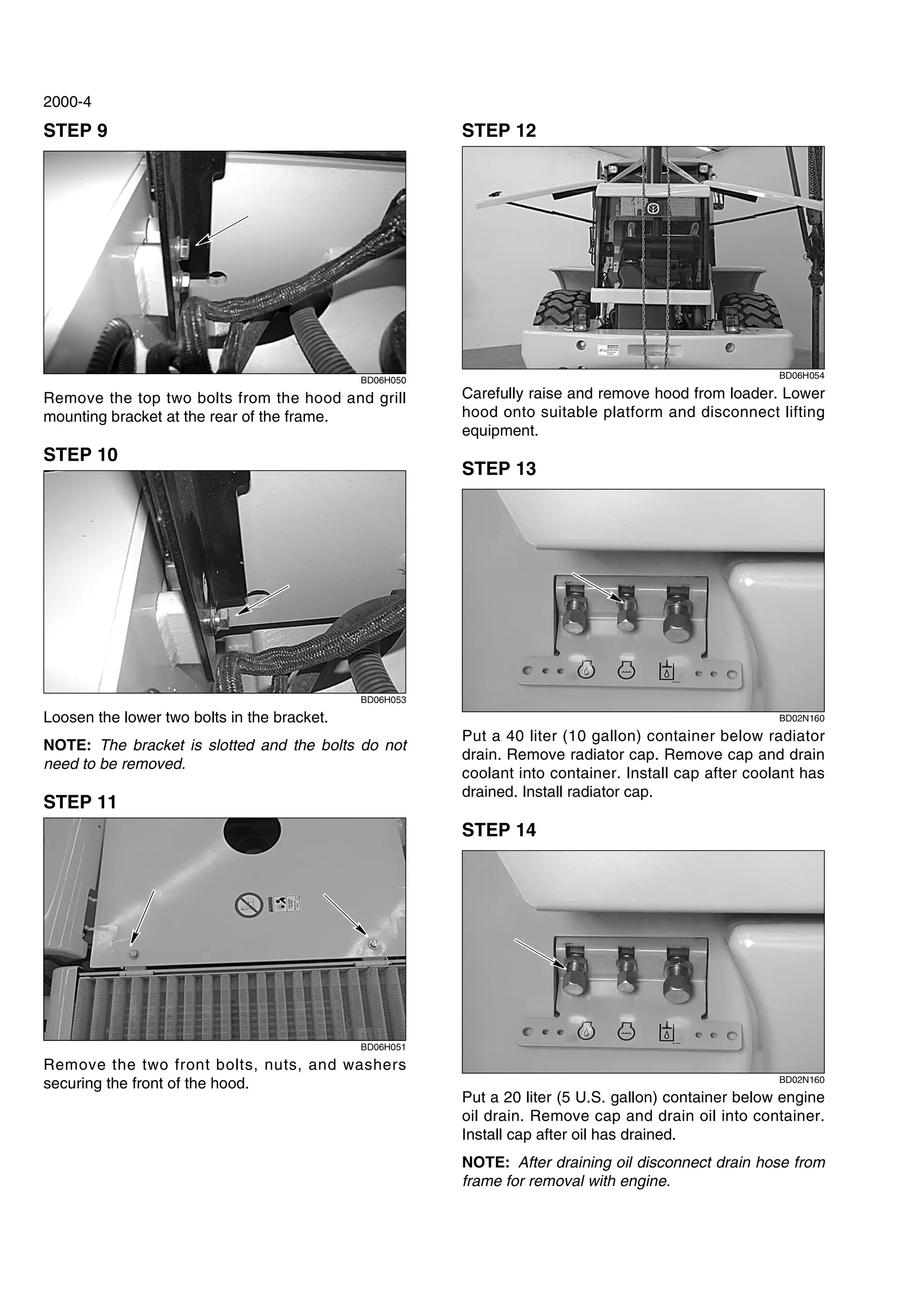
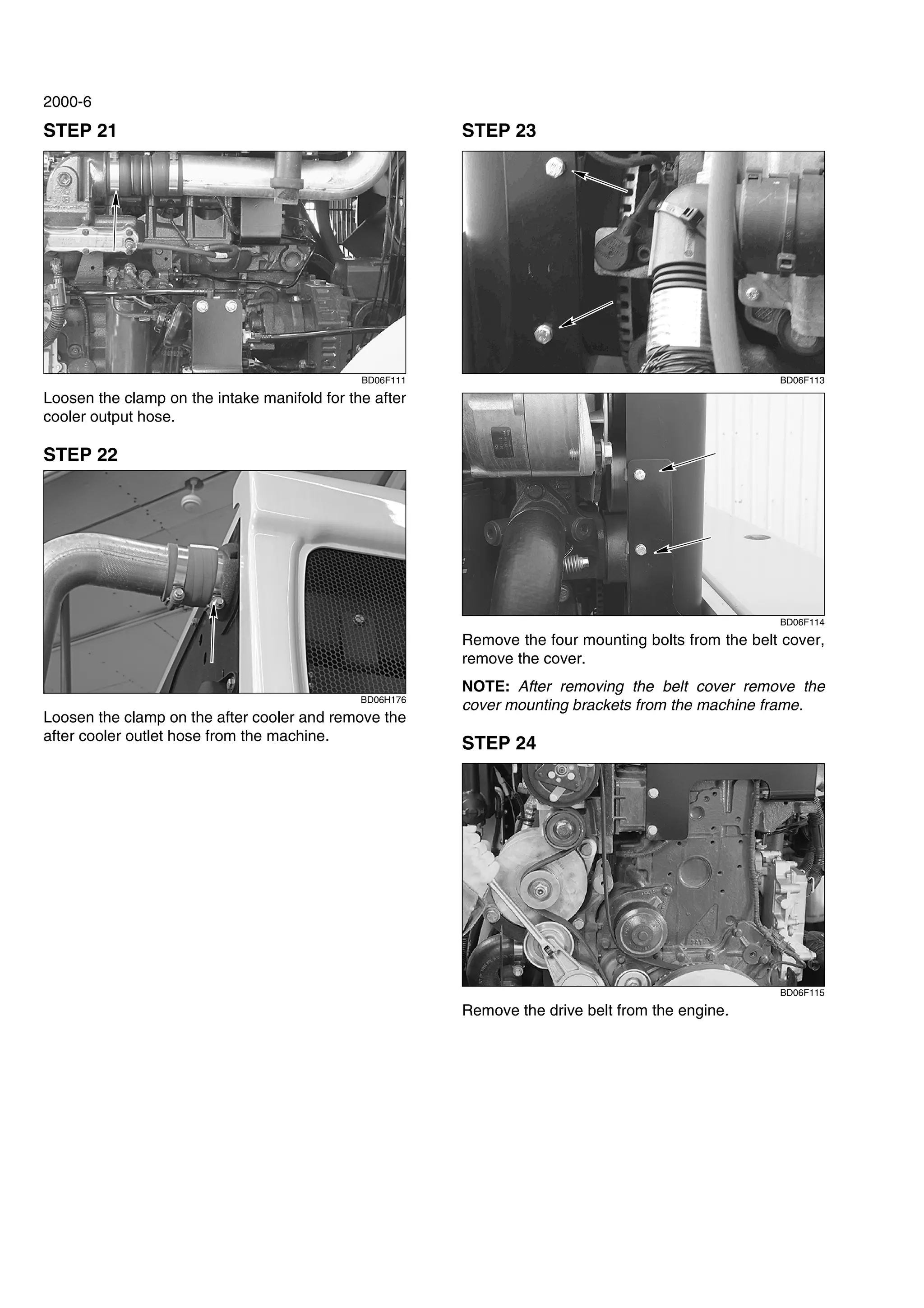
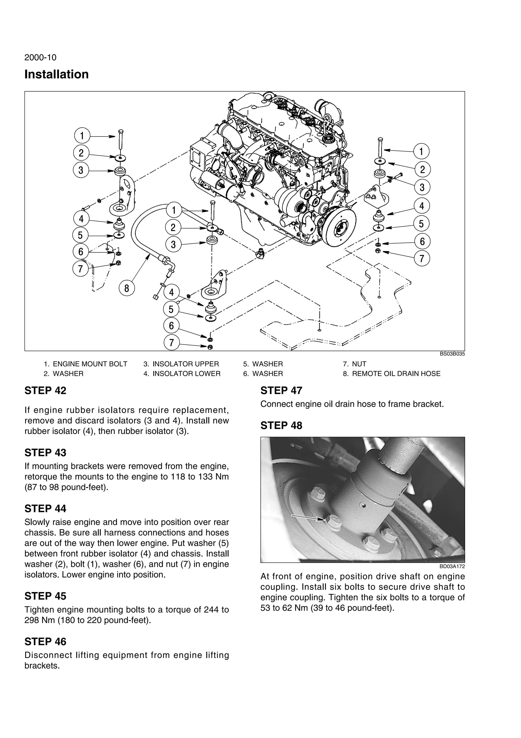
PT fuel system is made from the fuel tank, float tank, filter, governor, PT fuel pump, injector and low- pressure pipeline and return pipe. When working, PT fuel pump is responsible for oil regulator, PT injector completes the tasks that generate high pressure and timing injection.
Lathe-Types, Parts, Feed Mechanisms, Specifications,Lathe Accessories and Att...rajguptanitw
Who could ever think of manufacturing metals and other materials like wood and plastic without the lathe machine? Since the lathe machine is an important tool used in the machining process, which is an integral process in the manufacturing technology, it is just fitting to learn about it.
Machining is one of the most important material removal methods in the technology of manufacturing. It is basically a collection of material working processes that involves other processes such as drilling, shaping, sawing, planning, reaming, and grinding among others. Machining is practically a part of the manufacture of all metals and other materials such as plastics, and wood as well. An important machine that is useful in machining is the lathe machine.
A lathe machine is generally used in metalworking, metal spinning, woodturning, and glassworking. The various operations that it can perform include the following: sanding, cutting, knurling, drilling, and deforming of tools that are employed in creating objects which have symmetry about the axis of rotation. Some of the most common products of the lathe machine are crankshafts, camshafts, table legs, bowls, and candlestick holders.
The first lathe machine that was ever developed was the two-person lathe machine which was designed by the Egyptians in about 1300 BC. Primarily, there are two things that are achieved in this lathe machine set-up. The first is the turning of the wood working piece manually by a rope; and the second is the cutting of shapes in the wood by the use of a sharp tool. As civilizations progressed, there have been constant modifications and improvements over the original two-person lathe machine, most importantly on the production of the rotary motion.
The production of the rotary motion therefore evolved according to the following procedures: the Egyptians manual turning by hand; the Romans addition of a turning bow; the introduction of the pedal in the Middle Ages; the use of the steam engines during the Industrial Revolution; the employment of individual electric motors in the 19th and mid 20th centuries; and the latest of which is the adaption of numerically controlled mechanisms in controlling the lathe machine.
For the lathe machine to function and perform its operations, various important parts are integrated together. These essentials parts make up the lathe machine.
JCB 3CX BACKHOE LOADER Service Repair Manual SN:2000000 Onwardsjhsjen kjsmemf
This is the Highly Detailed factory service repair manual for theJCB 3CX BACKHOE LOADER, this Service Manual has detailed illustrations as well as step by step instructions,It is 100 percents complete and intact. they are specifically written for the do-it-yourself-er as well as the experienced mechanic.JCB 3CX BACKHOE LOADER Service Repair Workshop Manual provides step-by-step instructions based on the complete dis-assembly of the machine. It is this level of detail, along with hundreds of photos and illustrations, that guide the reader through each service and repair procedure. Complete download comes in pdf format which can work under all PC based windows operating system and Mac also, All pages are printable. Using this repair manual is an inexpensive way to keep your vehicle working properly.
Service Repair Manual Covers:
General Information
Care and Safety
Maintenance
Attachments
Body and Framework
Electrics
Hydraulics
Transmission
Brakes
Steering
Engine
Electronic Network
File Format: PDF
Compatible: All Versions of Windows & Mac
Language: English
Requirements: Adobe PDF Reader
NO waiting, Buy from responsible seller and get INSTANT DOWNLOAD, Without wasting your hard-owned money on uncertainty or surprise! All pages are is great to haveJCB 3CX BACKHOE LOADER Service Repair Workshop Manual.
Looking for some other Service Repair Manual,please check:
https://www.aservicemanualpdf.com/
Thanks for visiting!
YALE B875 GDP050VX LIFT TRUCK Service Repair Manualjkmdm eksmd
This is the Highly Detailed factory service repair manual for theYALE B875 GDP050VX LIFT TRUCK, this Service Manual has detailed illustrations as well as step by step instructions,It is 100 percents complete and intact. they are specifically written for the do-it-yourself-er as well as the experienced mechanic.YALE B875 GDP050VX LIFT TRUCK Service Repair Workshop Manual provides step-by-step instructions based on the complete dis-assembly of the machine. It is this level of detail, along with hundreds of photos and illustrations, that guide the reader through each service and repair procedure. Complete download comes in pdf format which can work under all PC based windows operating system and Mac also, All pages are printable. Using this repair manual is an inexpensive way to keep your vehicle working properly.
Service Repair Manual Covers:
Frame
Operator's cab
Gm 2.4l engine repair
Mazda fe and f2 engines
Y anmar diesel engines
Cooling system
Lpg fuel system (gm)
Gasoline fuel system gm 2.4l engine
Gasoline fuel system (mazda)
Gasoline fuel system mazda 2.0l and 2.2l 2007 emission compliant engines
Lpg fuel system mazda 2.0l and 2.2l 2007 emission compliant engines
1 and 2-speed powershift transmission repair
Single speed powershift aluminum transmission repair
Single speed powershift aluminum chain drive transmission
Powershift transmission repair
Drive axle - dry brake
Drive axle (wet brake)
Steering axle
Brake system
Hydraulic gear pump
Hydraulic cleanliness procedures
Main control valve
Cylinder repair (mast s/n a551, a555, a559, a661, a662, a663, a66, b507,
B508, b509, b551, b555, b559, b562, b563, b564, b661, b662, b663, c515,
C551, c555, c559, d507, d508, d509, d515, d562, d563, d564, e509, and e564)
Cylinder repair (mast s/n f507, f508, f562, f563)
Wire harness repair
User interface
Electrical system
Electrical system mazda 2.0l and 2.2l 2007 emission compliant engines
Mast repairs (s/n a551, a555, a559, a661, a662, a663, a664, b507, b508,
B509, b551, b555, b559, b562, b563, b564, b661, b662, b663, c515, c551,
C555, c559, d507, d508, d509, d515, d562, d563, d564, e509, and e564)
Mast repair (s/n f507, f508, f562, f563)
Metric and inch (sae) fasteners
Calibration procedures
Periodic maintenance
Capacities and specifications
Diagrams
Diagrams and schematics
Diagnostic troubleshooting manual
File Format: PDF
Compatible: All Versions of Windows & Mac
Language: English
Requirements: Adobe PDF Reader
NO waiting, Buy from responsible seller and get INSTANT DOWNLOAD, Without wasting your hard-owned money on uncertainty or surprise! All pages are is great to haveYALE B875 GDP050VX LIFT TRUCK Service Repair Workshop Manual.
Looking for some other Service Repair Manual,please check:
https://www.aservicemanualpdf.com/
Thanks for visiting!
8
Unit 5- balancing of reciprocating masses, Dynamics of machines of VTU Syllabus prepared by Hareesha N Gowda, Asst. Prof, Dayananda Sagar College of Engg, Blore. Please write to hareeshang@gmail.com for suggestions and criticisms.
Toyota 02-5FG45 Forklift Service Repair Manualjjkmsmnj
This is the Highly Detailed factory service repair manual for theTOYOTA 02-5FG45 FORKLIFT, this Service Manual has detailed illustrations as well as step by step instructions,It is 100 percents complete and intact. they are specifically written for the do-it-yourself-er as well as the experienced mechanic.TOYOTA 02-5FG45 FORKLIFT Service Repair Workshop Manual provides step-by-step instructions based on the complete dis-assembly of the machine. It is this level of detail, along with hundreds of photos and illustrations, that guide the reader through each service and repair procedure. Complete download comes in pdf format which can work under all PC based windows operating system and Mac also, All pages are printable. Using this repair manual is an inexpensive way to keep your vehicle working properly.
Service Repair Manual Covers:
General
Engine
Clutch
Torque Converter
Transmission and Differential
Front Axle
Rear Axle
Steering
Brake
Body
Material Handling System
Mast
Cylinder
Oil Pump
Oil Control Vavle
Appendix
File Format: PDF
Compatible: All Versions of Windows & Mac
Language: English
Requirements: Adobe PDF Reader
NO waiting, Buy from responsible seller and get INSTANT DOWNLOAD, Without wasting your hard-owned money on uncertainty or surprise! All pages are is great to haveTOYOTA 02-5FG45 FORKLIFT Service Repair Workshop Manual.
Looking for some other Service Repair Manual,please check:
https://www.aservicemanualpdf.com/
Thanks for visiting!
8
What Exactly Is The Common Rail Direct Injection System & How Does It WorkMotor Cars International
Learn about Common Rail Direct Injection (CRDi) - the revolutionary technology that has made diesel engines more efficient. Explore its workings, advantages like enhanced fuel efficiency and increased power output, along with drawbacks such as complexity and higher initial cost. Compare CRDi with traditional diesel engines and discover why it's the preferred choice for modern engines.
5 Warning Signs Your BMW's Intelligent Battery Sensor Needs AttentionBertini's German Motors
IBS monitors and manages your BMW’s battery performance. If it malfunctions, you will have to deal with an array of electrical issues in your vehicle. Recognize warning signs like dimming headlights, frequent battery replacements, and electrical malfunctions to address potential IBS issues promptly.
What Does the Active Steering Malfunction Warning Mean for Your BMWTanner Motors
Discover the reasons why your BMW’s Active Steering malfunction warning might come on. From electrical glitches to mechanical failures and software anomalies, addressing these promptly with professional inspection and maintenance ensures continued safety and performance on the road, maintaining the integrity of your driving experience.
In this presentation, we have discussed a very important feature of BMW X5 cars… the Comfort Access. Things that can significantly limit its functionality. And things that you can try to restore the functionality of such a convenient feature of your vehicle.
Comprehensive program for Agricultural Finance, the Automotive Sector, and Empowerment . We will define the full scope and provide a detailed two-week plan for identifying strategic partners in each area within Limpopo, including target areas.:
1. Agricultural : Supporting Primary and Secondary Agriculture
• Scope: Provide support solutions to enhance agricultural productivity and sustainability.
• Target Areas: Polokwane, Tzaneen, Thohoyandou, Makhado, and Giyani.
2. Automotive Sector: Partnerships with Mechanics and Panel Beater Shops
• Scope: Develop collaborations with automotive service providers to improve service quality and business operations.
• Target Areas: Polokwane, Lephalale, Mokopane, Phalaborwa, and Bela-Bela.
3. Empowerment : Focusing on Women Empowerment
• Scope: Provide business support support and training to women-owned businesses, promoting economic inclusion.
• Target Areas: Polokwane, Thohoyandou, Musina, Burgersfort, and Louis Trichardt.
We will also prioritize Industrial Economic Zone areas and their priorities.
Sign up on https://profilesmes.online/welcome/
To be eligible:
1. You must have a registered business and operate in Limpopo
2. Generate revenue
3. Sectors : Agriculture ( primary and secondary) and Automative
Women and Youth are encouraged to apply even if you don't fall in those sectors.
Why Is Your BMW X3 Hood Not Responding To Release CommandsDart Auto
Experiencing difficulty opening your BMW X3's hood? This guide explores potential issues like mechanical obstruction, hood release mechanism failure, electrical problems, and emergency release malfunctions. Troubleshooting tips include basic checks, clearing obstructions, applying pressure, and using the emergency release.
"Trans Failsafe Prog" on your BMW X5 indicates potential transmission issues requiring immediate action. This safety feature activates in response to abnormalities like low fluid levels, leaks, faulty sensors, electrical or mechanical failures, and overheating.
Symptoms like intermittent starting and key recognition errors signal potential problems with your Mercedes’ EIS. Use diagnostic steps like error code checks and spare key tests. Professional diagnosis and solutions like EIS replacement ensure safe driving. Consult a qualified technician for accurate diagnosis and repair.
What Does the PARKTRONIC Inoperative, See Owner's Manual Message Mean for You...Autohaus Service and Sales
Learn what "PARKTRONIC Inoperative, See Owner's Manual" means for your Mercedes-Benz. This message indicates a malfunction in the parking assistance system, potentially due to sensor issues or electrical faults. Prompt attention is crucial to ensure safety and functionality. Follow steps outlined for diagnosis and repair in the owner's manual.
Core technology of Hyundai Motor Group's EV platform 'E-GMP'Hyundai Motor Group
What’s the force behind Hyundai Motor Group's EV performance and quality?
Maximized driving performance and quick charging time through high-density battery pack and fast charging technology and applicable to various vehicle types!
Discover more about Hyundai Motor Group’s EV platform ‘E-GMP’!
Things to remember while upgrading the brakes of your carjennifermiller8137
Upgrading the brakes of your car? Keep these things in mind before doing so. Additionally, start using an OBD 2 GPS tracker so that you never miss a vehicle maintenance appointment. On top of this, a car GPS tracker will also let you master good driving habits that will let you increase the operational life of your car’s brakes.
𝘼𝙣𝙩𝙞𝙦𝙪𝙚 𝙋𝙡𝙖𝙨𝙩𝙞𝙘 𝙏𝙧𝙖𝙙𝙚𝙧𝙨 𝙞𝙨 𝙫𝙚𝙧𝙮 𝙛𝙖𝙢𝙤𝙪𝙨 𝙛𝙤𝙧 𝙢𝙖𝙣𝙪𝙛𝙖𝙘𝙩𝙪𝙧𝙞𝙣𝙜 𝙩𝙝𝙚𝙞𝙧 𝙥𝙧𝙤𝙙𝙪𝙘𝙩𝙨. 𝙒𝙚 𝙝𝙖𝙫𝙚 𝙖𝙡𝙡 𝙩𝙝𝙚 𝙥𝙡𝙖𝙨𝙩𝙞𝙘 𝙜𝙧𝙖𝙣𝙪𝙡𝙚𝙨 𝙪𝙨𝙚𝙙 𝙞𝙣 𝙖𝙪𝙩𝙤𝙢𝙤𝙩𝙞𝙫𝙚 𝙖𝙣𝙙 𝙖𝙪𝙩𝙤 𝙥𝙖𝙧𝙩𝙨 𝙖𝙣𝙙 𝙖𝙡𝙡 𝙩𝙝𝙚 𝙛𝙖𝙢𝙤𝙪𝙨 𝙘𝙤𝙢𝙥𝙖𝙣𝙞𝙚𝙨 𝙗𝙪𝙮 𝙩𝙝𝙚 𝙜𝙧𝙖𝙣𝙪𝙡𝙚𝙨 𝙛𝙧𝙤𝙢 𝙪𝙨.
Over the 10 years, we have gained a strong foothold in the market due to our range's high quality, competitive prices, and time-lined delivery schedules.
3. Steering Tab 5
Section Index - Steering
Removal and Installation of Steering Components 5001
Steering Specifications, Pressure Checks, and Troubleshooting 5002
Steering Cylinders 5005
Center Pivot 5006
Auxiliary Steering Motor and Pump 5007
Power Train Tab 6
Section Index - Power Train
Removal and Installation of Power Train Components 6001
Transmission Specifications, Pressure Checks, and Troubleshooting 6002
Transmission 6003
Front Axle 6004
Rear Axle 6004
Drive Shafts, Center Bearing, and Universal Joints 6005
Wheels and Tires 6006
Transmission Control Valve 6007
Brakes Tab 7
Section Index - Brakes
Removal and Installation of Brake Components 7001
Hydraulic Brake Troubleshooting 7002
Brake Pump 7003
Brake Accumulators 7004
Parking Brake 7008
Hydraulics Tab 8
Section Index - Hydraulics
Removal and Installation of Hydraulic Components 8001
Hydraulic Specifications, Troubleshooting, and Pressure Checks 8002
Cleaning the Hydraulic System 8003
Hydraulic Pump 8004
Loader Control Valve 8005
Cylinders 8006
Coupler Solenoid Locking Valve 8007
Pilot Pressure Accumulator and Ride Control Accumulator 8013
Ride Control Valve 8014
W170B Wheel Loader
Service Manual
87614924
Table of Contents
Description Section No.
6. 1001-3
TORQUE SPECIFICATIONS - DECIMAL HARDWARE
Use the torques in this chart when special torques
are not given. These torques apply to fasteners with
both UNC and UNF threads as received from
suppliers dry, or when lubricated with engine oil. Not
applicable if special graphities, Molydisulfide
greases, or other extreme pressure lubricants are
used.
Grade 5 Bolts, Nuts, and Studs
Size
Pound-
Inches
Newton
metres
1/4 inch 108 to 132 12 to 15
5/16 inch 204 to 252 23 to 28
3/8 inch 420 to 504 48 to 57
Size
Pound-
Feet
Newton
metres
7/16 inch 54 to 64 73 to 87
1/2 inch 80 to 96 109 to 130
9/16 inch 110 to 132 149 to 179
5/8 inch 150 to 180 203 to 244
3/4 inch 270 to 324 366 to 439
7/8 inch 400 to 480 542 to 651
1.0 inch 580 to 696 787 to 944
1-1/8 inch 800 to 880 1085 to 1193
1-1/4 inch 1120 to 1240 1519 to 1681
1-3/8 inch 1460 to 1680 1980 to 2278
1-1/2 inch 1940 to 2200 2631 to 2983
Grade 8 Bolts, Nuts, and Studs
Size
Pound-
Inches
Newton
metres
1/4 inch 144 to 180 16 to 20
5/16 inch 288 to 348 33 to 39
3/8 inch 540 to 648 61 to 73
Size
Pound-
Feet
Newton
metres
7/16 inch 70 to 84 95 to 114
1/2 inch 110 to 132 149 to 179
9/16 inch 160 to 192 217 to 260
5/8 inch 220 to 264 298 to 358
3/4 inch 380 to 456 515 to 618
7/8 inch 600 to 720 814 to 976
1.0 inch 900 to 1080 1220 to 1465
1-1/8 inch 1280 to 1440 1736 to 1953
1-1/4 inch 1820 to 2000 2468 to 2712
1-3/8 inch 2380 to 2720 3227 to 3688
1-1/2 inch 3160 to 3560 4285 to 4827
NOTE: Use thick nuts with Grade 8 bolts.
7. 1001-4
TORQUE SPECIFICATIONS - METRIC HARDWARE
Use the following torques when specifications are not
given.
These values apply to fasteners with coarse threads
as received from supplier, plated or unplated, or
when lubricated with engine oil. These values do not
apply if graphite or Molydisulfide grease or oil is
used.
Grade 12.9 Bolts, Nuts, and Studs
Usually the torque values specified for grade 10.9
fasteners can be used satisfactorily on grade 12.9
fasteners.
Grade 8.8 Bolts, Nuts, and Studs
Size
Pound-
Inches
Newton
metres
M4 24 to 36 3 to 4
M5 60 to 72 7 to 8
M6 96 to 108 11 to 12
M8 228 to 276 26 to 31
M10 456 to 540 52 to 61
Size
Pound-
Feet
Newton
metres
M12 66 to 79 90 to 107
M14 106 to 127 144 to 172
M16 160 to 200 217 to 271
M20 320 to 380 434 to 515
M24 500 to 600 675 to 815
M30 920 to 1100 1250 to 1500
M36 1600 to 1950 2175 to 2600
8.8
Grade 10.9 Bolts, Nuts, and Studs
Size
Pound-
Inches
Newton
metres
M4 36 to 48 4 to 5
M5 84 to 96 9 to 11
M6 132 to 156 15 to 18
M8 324 to 384 37 to 43
Size
Pound-
Feet
Newton
metres
M10 54 to 64 73 to 87
M12 93 to 112 125 to 150
M14 149 to 179 200 to 245
M16 230 to 280 310 to 380
M20 450 to 540 610 to 730
M24 780 to 940 1050 to 1275
M30 1470 to 1770 2000 to 2400
M36 2580 to 3090 3500 to 4200
10.9
12.9
8. 1001-5
TORQUE SPECIFICATIONS - STEEL HYDRAULIC FITTINGS
Tube OD
Hose ID
Thread
Size
Pound-
Inches
Newton
metres
37 Degree Flare Fitting
1/4 inch
6.4 mm
7/16-20 72 to 144 8 to 16
5/16 inch
7.9 mm
1/2-20 96 to 192 11 to 22
3/8 inch
9.5 mm
9/16-18 120 to 300 14 to 34
1/2 inch
12.7 mm
3/4-16 180 to 504 20 to 57
5/8 inch
15.9 mm
7/8-14 300 to 696 34 to 79
Tube OD
Hose ID
Thread
Size
Pound-
Inches
Newton
metres
3/4 inch
19.0 mm
1-1/16-12 40 to 80 54 to 108
7/8 inch
22.2 mm
1-3/16-12 60 to 100 81 to 135
1.0 inch
25.4 mm
1-5/16-12 75 to 117 102 to 158
1-1/4 inch
31.8 mm
1-5/8-12 125 to 165 169 to 223
1-1/2 inch
38.1 mm
1-7/8-12 210 to 250 285 to 338
Split Flange Mounting Bolts
Size
Pound-
Inches
Newton
metres
5/16-18 180 to 240 20 to 27
3/8-16 240 to 300 27 to 34
7/16-14 420 to 540 47 to 61
Size
Pound-
Feet
Newton
metres
1/2-13 55 to 65 74 to 88
5/8-11 140 to 150 190 to 203
Tube OD
Hose ID
Thread
Size
Pound-
Inches
Newton
metres
Straight Threads with O-ring
1/4 inch
6.4 mm
7/16-20 144 to 228 16 to 26
5/16 inch
7.9 mm
1/2-20 192 to 300 22 to 34
3/8 inch
9.5 mm
9/16-18 300 to 480 34 to 54
1/2 inch
12.7 mm
3/4-16 540 to 804 57 to 91
Tube OD
Hose ID
Thread
Size
Pound-
Inches
Newton
metres
5/8 inch
15.9 mm
7/8-14 58 to 92 79 to 124
3/4 inch
19.0 mm
1-1/16-12 80 to 128 108 to 174
7/8 inch
22.2 mm
1-3/16-12 100 to 160 136 to 216
1.0 inch
25.4 mm
1-5/16-12 117 to 187 159 to 253
1-1/4 inch
31.8 mm
1-5/8-12 165 to 264 224 to 357
1-1/2 inch
38.1 mm
1-7/8-12 250 to 400 339 to 542
10. 2000-3
ENGINE
Removal
STEP 1
BD03A040
Park machine on a level surface and lower bucket to
ground. Put articulation lock in LOCKED position.
STEP 2
Stop engine. Actuate brake pedal several times to
discharge brake accumulators. Put key switch in ON
position and move loader control lever back and forth
at least 30 times to release any pressure from
hydraulic circuit. Put key switch in OFF position.
STEP 3
Slowly loosen the filler cap for hydraulic reservoir to
release air pressure in hydraulic reservoir.
STEP 4
Put master disconnect switch in OFF position.
Disconnect batteries from the machine.
STEP 5
BD06H046
Disconnect the backup alarm.
STEP 6
BD06H047
Loosen clamps and remove air filter intake from air
filter.
STEP 7
BD06H048
Run a lifting strap through the back hinge on each
side of the hood, route the strap behind the exhaust
stack.
STEP 8
BD06H052
Route the strap in front of the exhaust stack, attach
lifting equipment to the strap, take up the slack.
11. 2000-4
STEP 9
BD06H050
Remove the top two bolts from the hood and grill
mounting bracket at the rear of the frame.
STEP 10
BD06H053
Loosen the lower two bolts in the bracket.
NOTE: The bracket is slotted and the bolts do not
need to be removed.
STEP 11
BD06H051
Remove the two front bolts, nuts, and washers
securing the front of the hood.
STEP 12
BD06H054
Carefully raise and remove hood from loader. Lower
hood onto suitable platform and disconnect lifting
equipment.
STEP 13
BD02N160
Put a 40 liter (10 gallon) container below radiator
drain. Remove radiator cap. Remove cap and drain
coolant into container. Install cap after coolant has
drained. Install radiator cap.
STEP 14
BD02N160
Put a 20 liter (5 U.S. gallon) container below engine
oil drain. Remove cap and drain oil into container.
Install cap after oil has drained.
NOTE: After draining oil disconnect drain hose from
frame for removal with engine.
12. 2000-5
STEP 15
BD06H055
Loosen clamp on air cleaner intake hose and remove
the crankcase ventilation hose.
STEP 16
BD06H056
Loosen clamps on turbocharger and air cleaner,
remove the intake hose.
STEP 17
BD06H057
Tag and disconnect engine wiring harness connector
from air filter restriction switch.
STEP 18
BD06H060
Disconnect the engine coolant vent hose and root to
the rear of the engine.
STEP 19
BD06H058
Loosen the clamp on the turbocharger for the after
cooler inlet hose.
STEP 20
BD06H059
Loosen the clamp on the after cooler and remove the
after cooler inlet hose from the machine.
13. 2000-6
STEP 21
BD06F111
Loosen the clamp on the intake manifold for the after
cooler output hose.
STEP 22
BD06H176
Loosen the clamp on the after cooler and remove the
after cooler outlet hose from the machine.
STEP 23
BD06F113
BD06F114
Remove the four mounting bolts from the belt cover,
remove the cover.
NOTE: After removing the belt cover remove the
cover mounting brackets from the machine frame.
STEP 24
BD06F115
Remove the drive belt from the engine.
14. 2000-7
STEP 25
BD06F116
Loosen clamps and remove lower cooler hose from
the engine.
STEP 26
BD06F117
If loader is equipped with air conditioning, identify,
tag, and disconnect the engine wiring harness
connectors from air compressor clutch connector (1).
Remove the three mounting bolts (2) for the
compressor and set the compressor on the left
battery cover.
STEP 27
BD06F118
Tag and disconnect the wiring from the alternator.
STEP 28
BD06F119
Remove bolt securing wiring harness clamp to
engine.
STEP 29
BD06F120
Remove bolt securing wiring harness clamp (1) to the
engine. Remove ground wires (2) from the engine.
STEP 30
BD06F121
Tag and remove the wires from the starter solenoid
(3), remove the ground cable (2), and ground strap
(1) from the starter.
NOTE: Move the starter cables away from the
engine, move the wiring harness away from the
engine.
1
2
1
2
3
1
2
15. 2000-8
STEP 31
BD06F122
Remove the radiator hose (1) from the rear of the
engine, remove the heater hose from the rear of the
engine (2), remove the clamp bolts and clamps (3)
from the bell housing.
STEP 32
BD06H061
Tag and remove the grid heater cable.
STEP 33
BD06H062
Disconnect the wiring harness from the EDC 7
controller.
NOTE: Lifting up on the lever will release the
connector from the controller.
STEP 34
BD06F123
Remove the fuel line from the top of the EDC 7
controller, plug the line and cap the fitting.
STEP 35
BD06H065
Tag and disconnect the fuel filter heater wires (1),
disconnect the fuel line (2) from the fuel filter head,
plug the line and cap the fitting.
STEP 36
BD06F125
Remove bolt and clamp and move the fuel return line
away from the engine.
2
1
3
1
2
16. 2000-9
STEP 37
BD06F126
Connect and turn on vacuum pump to hydraulic
reservoir. Tag and remove the hydraulic lines from
the brake system pump, plug the lines and cap the
fittings.
STEP 38
BD06F127
Remove the lower cover for the drive shaft.
STEP 39
BD03A172
Remove the drive shaft bolts from the flywheel. Move
the drive shaft clear of the flywheel.
STEP 40
Connect suitable lifting equipment to engine lifting
brackets. Take up all slack in lifting equipment.
Remove the engine mounting bolts and lift the engine
enough to gain access to the drain hose, pull the
drain hose with the engine.
STEP 41
Slowly raise engine from rear chassis. Be sure all
harness connections and hoses have been
disconnected and are clear of the engine. Remove
engine from machine.
17. 2000-10
Installation
BS03B035
STEP 42
If engine rubber isolators require replacement,
remove and discard isolators (3 and 4). Install new
rubber isolator (4), then rubber isolator (3).
STEP 43
If mounting brackets were removed from the engine,
retorque the mounts to the engine to 118 to 133 Nm
(87 to 98 pound-feet).
STEP 44
Slowly raise engine and move into position over rear
chassis. Be sure all harness connections and hoses
are out of the way then lower engine. Put washer (5)
between front rubber isolator (4) and chassis. Install
washer (2), bolt (1), washer (6), and nut (7) in engine
isolators. Lower engine into position.
STEP 45
Tighten engine mounting bolts to a torque of 244 to
298 Nm (180 to 220 pound-feet).
STEP 46
Disconnect lifting equipment from engine lifting
brackets.
STEP 47
Connect engine oil drain hose to frame bracket.
STEP 48
BD03A172
At front of engine, position drive shaft on engine
coupling. Install six bolts to secure drive shaft to
engine coupling. Tighten the six bolts to a torque of
53 to 62 Nm (39 to 46 pound-feet).
1. ENGINE MOUNT BOLT 3. INSOLATOR UPPER 5. WASHER 7. NUT
2. WASHER 4. INSOLATOR LOWER 6. WASHER 8. REMOTE OIL DRAIN HOSE
1
4
3
2
7
6
5
4
3
2
1
1
7
8
7
6
5
2
3
4
5
6
18. 2000-11
STEP 49
BD06F127
Install the lower cover for the drive shaft.
STEP 50
BD06F126
Connect and turn on vacuum pump to the hydraulic
reservoir. Remove caps from fittings and plugs from
hoses. Connect hoses to brake pump following tags
installed during removal. Remove and discard tags.
Turn off and disconnect vacuum pump from hydraulic
reservoir.
STEP 51
BD06F125
Install bolt and clamp for fuel return hose.
STEP 52
BD06H065
Remove cap from fitting and plug from the hose,
connect fuel line (2). Connect fuel filter heater wires
(1). Remove and discard tag.
STEP 53
BD06F123
Remove cap from fitting and plug from the hose,
connect fuel line to EDC 7.
STEP 54
BD06H062
Connect wiring harness to EDC 7 controller.
NOTE: Start the connector on the EDC 7 with lever
straight out from EDC 7. Use lever to pull connector
into position.
1
2
19. 2000-12
STEP 55
BD06H061
Connect grid heater cable to grid heater. Remove
and discard tag.
STEP 56
BD06F122
Install the heater hose (2) to the rear of the engine,
mount the clamps (3), install the radiator hose (1).
STEP 57
BD06H060
Connect the engine coolant vent hose.
STEP 58
BD06F121
Install the wires to the starter solenoid (3), install the
ground cable (2), and ground strap (1) to the starter.
Remove and discard tags.
STEP 59
BD06F120
Install bolt securing wiring harness (1) clamp to the
engine. Install ground wires (2) to the engine.
STEP 60
BD06F119
Install bolt securing wiring harness clamp to engine.
2
1
3
3
1
2
1
2
20. 2000-13
STEP 61
BD06F118
Connect the wiring to the alternator. Remove and
discard tags.
STEP 62
BD06F117
If loader is equipped with air conditioning, mount the
compressor using the three mounting bolts (2),
connect the engine wiring harness connectors to air
compressor clutch connector (1). Remove and
discard tags.
STEP 63
BD06F116
Install lower cooler hose to the engine and tighten
the clamps to a torque of 10.1 to 11.3 Nm (90 to 100
lb-inch).
STEP 64
BD06F115
Install the drive belt.
STEP 65
BD06F113
BD06F114
Install the cover mounting brackets to the machine
frame. Install the belt cover, install the four mounting
bolts for the belt cover.
1
2
21. 2000-14
STEP 66
BD06H176
Place the after cooler outlet hose on the machine.
Tighten the clamp on the after cooler.
STEP 67
BD06F111
Tighten the clamp on the intake manifold for the after
cooler output hose.
STEP 68
BD06H059
Place the after cooler inlet hose on the machine.
Tighten the clamp on the after cooler.
STEP 69
BD06H057
Connect engine wiring harness connector to air filter
restriction switch. Remove and discard tag.
STEP 70
BD06H058
Tighten the clamp on the turbocharger for the after
cooler inlet hose.
STEP 71
BD06H056
Install the intake hose and tighten the clamps on
turbocharger and air cleaner.
22. Thank you very much for
your reading. Please Click
Here. Then Get COMPLETE
MANUAL. NO WAITING
NOTE:
If there is no response to
click on the link above,
please download the PDF
document first and then
click on it.
23. 2000-15
STEP 72
BD06H055
Install the crankcase ventilation hose and tighten the
clamp on air cleaner intake hose.
STEP 73
BD06H054
Carefully raise and position the hood onto loader,
lower the hood and grill brackets onto the two lower
bolts at the rear of the frame.
STEP 74
BD06H051
Install the two front bolts and washers securing the
front of the hood.
STEP 75
BD06H049
Use two new self locking nuts on the front bolts,
tighten and secure the hood.
STEP 76
BD06H050
Install two top bolts and washers, one on each side
of the machine, securing the hood to the rear frame,
tighten all four bolts.
STEP 77
BD02N160
Check and make sure that drain caps are tight.
STEP 78
Install a new oil filter on engine. Fill engine with oil,
see section 1002 for specifications.
24. 2000-16
STEP 79
If hydraulic reservoir was drained, fill reservoir with
oil, see section 1002 for specifications.
STEP 80
Fill engine coolant system with a solution of 50%
Ethylene Glycol and 50% water. Fill cooling system,
see section 1002 for specifications. Install the
radiator cap. Fill the coolant reservoir up to the FULL
mark on the reservoir.
STEP 81
Connect the batteries, install battery covers, put
master disconnect switch in ON position.
STEP 82
Start engine and run the engine at low idle. Run the
engine at operating temperature for approximately
five minutes to completely mix the Ethylene Glycol
and water. When the coolant is at operating
temperature, stop the engine. When engine has
cooled, check the coolant level at the reservoir.
WARNING: Hot coolant can spray out if radiator cap
is removed. To remove radiator cap: Let system cool,
turn to first notch, then wait until all pressure is
released. Scalding can result from fast removal of
radiator cap.
STEP 83
Put articulation lock in OPERATING position.
25. 2000-17
RADIATOR
Removal
STEP 84
Park loader on level surface and lower bucket to
ground. Apply parking brake and shut down engine.
STEP 85
BD00M030
Put articulation lock in LOCKED position.
STEP 86
Open and raise hood.
STEP 87
Put master disconnect switch in OFF position.
STEP 88
Remove bolt and washer securing LH fender.
Remove LH fender.
STEP 89
BD00M031
Put a 37.8 liter (10 gallon) container below radiator
drain. Remove cap and drain coolant into container.
Install cap after coolant has drained.
STEP 90
BD01D188
At top of cooling system frame, loosen two hose
clamps (1). Remove hose (2).
STEP 91
BD01D229
Loosen two clamps securing radiator bottom hose.
Remove bottom hose.
STEP 92
BD01D223
1. HOSE CLAMP 2. HOSE
1. RADIATOR CAP 3. SCREW
2. OVERFLOW HOSE
1
1
2
3
1 2
26. 2000-18
Remove radiator cap (1) and disconnect overflow
hose (2) from radiator. Install radiator cap. Remove
screw (3) and install lifting eye.
STEP 93
BD01D226
Remove two bolts and lock washers on sides of
radiator. Remove screw and install lifting eye.
STEP 94
BD01D227
Connect lifting equipment to lifting eyes. Take up all
slack in lifting equipment.
STEP 95
BD01D225
Remove four bolts and lock washers securing
radiator to cooling frame. Carefully and slowly raise
radiator from cooling frame and remove from loader.
Installation
STEP 96
Move radiator into position above cooling frame.
Carefully lower radiator while guiding it into position
in cooling frame.
STEP 97
BD01D225
Install four lock washers and bolts to secure radiator
to cooling frame.
STEP 98
BD01D227
Disconnect lifting equipment from lifting eyes.
27. 2000-19
STEP 99
BD01D226
Remove lifting eye and install screw. Install two lock
washers and bolts to secure radiator on both sides.
STEP 100
BD01D223
Remove lifting eye and install screw (3). Remove
radiator cap (1) and connect overflow hose (2) to
radiator. Install radiator cap.
STEP 101
BD01D229
At bottom of radiator, install bottom radiator hose.
Position and tighten two hose clamps to a torque of
10.1 to 11.3 Nm (90 to 100 lb-inch).
STEP 102
BD01D188
At top of cooling system frame, install hose (2).
Position hose clamps (1) and tighten to a torque of
10.1 to 11.3 Nm (90 to 100 lb-inch).
STEP 103
Install LH fender. Install two bolts and washers to
secure LH fender.
STEP 104
BD00M031
Check that coolant drain cap is tight.
STEP 105
Fill engine coolant system with a solution of 50%
Ethylene Glycol and 50% water. Cooling system
capacity is 34.1 liters (9 gallons). Install the radiator
cap. Fill the coolant reservoir up to the FULL mark on
the reservoir.
STEP 106
Put master disconnect switch in ON position.
1. RADIATOR CAP 3. SCREW
2. OVERFLOW HOSE
3
1 2
1. HOSE CLAMP 2. HOSE
1
1
2