Downloaded 290 times
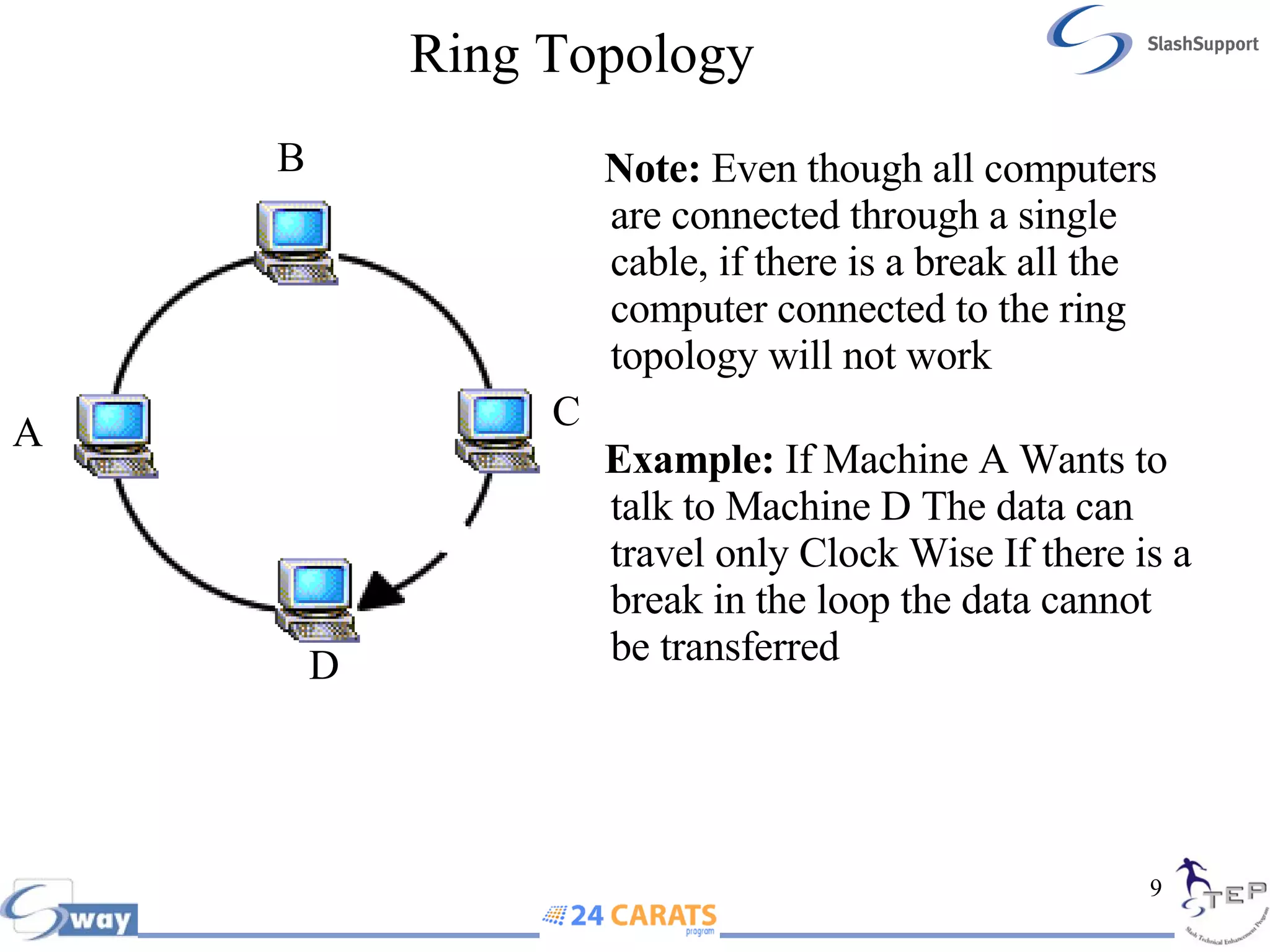
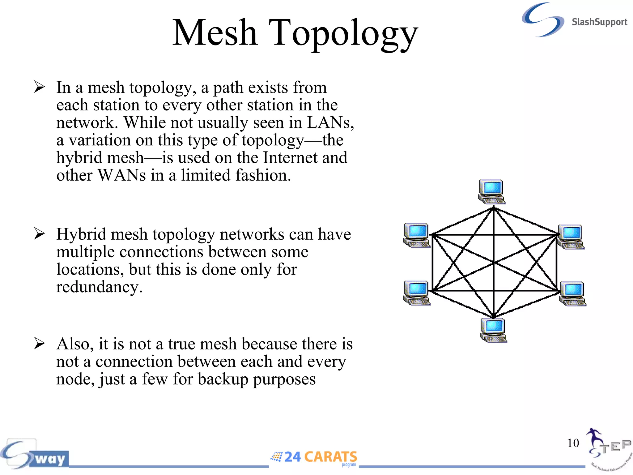
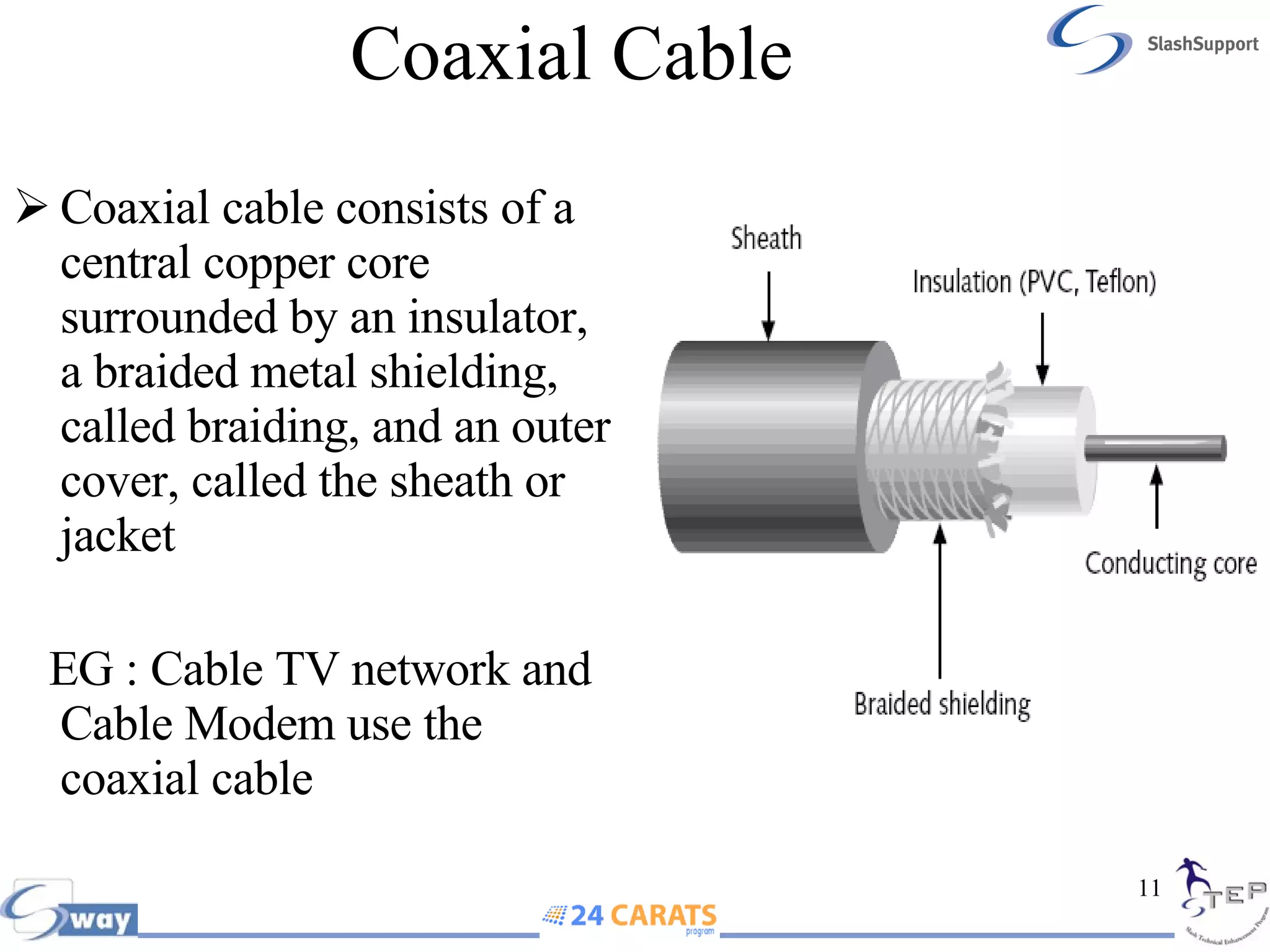
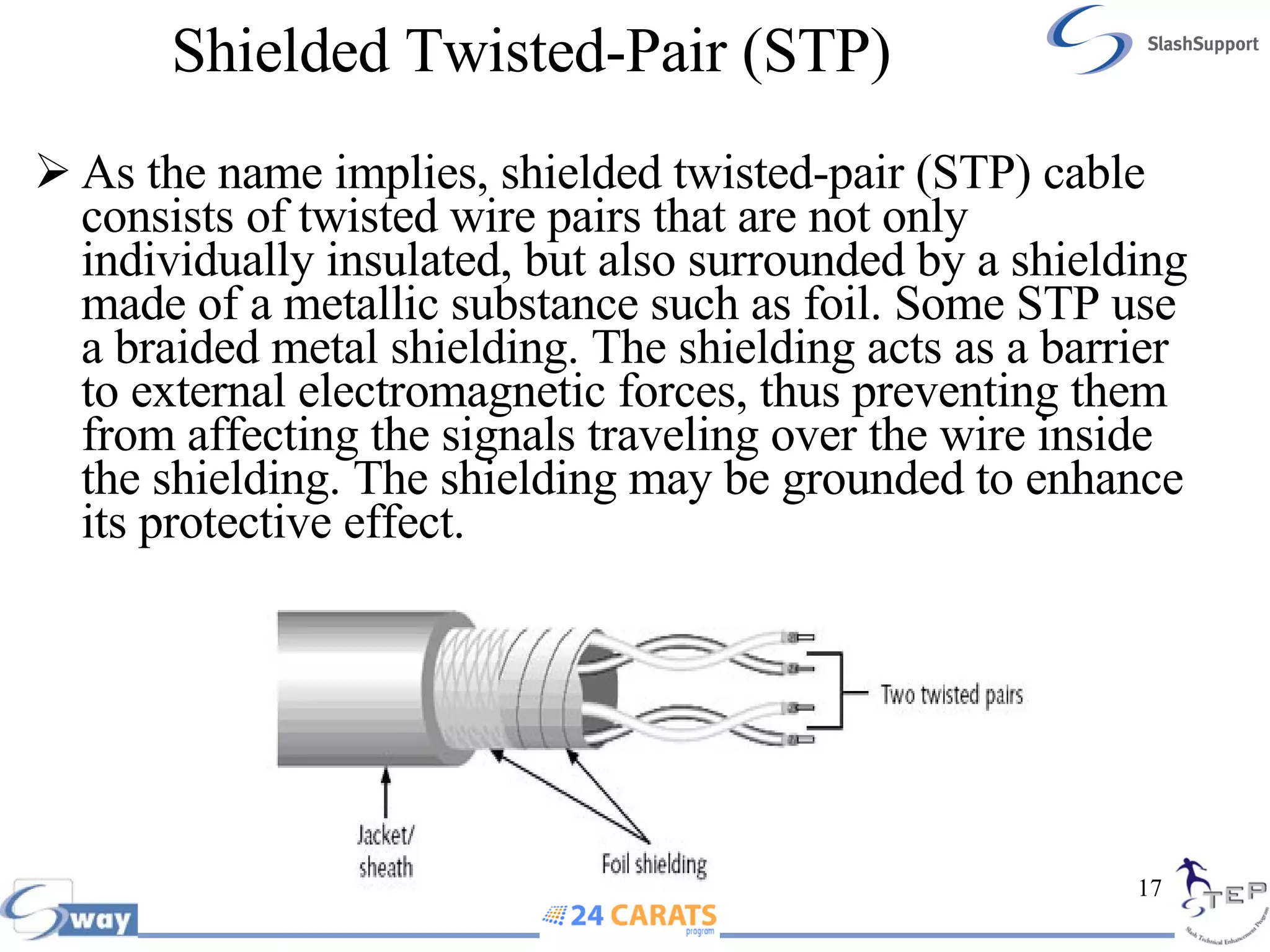
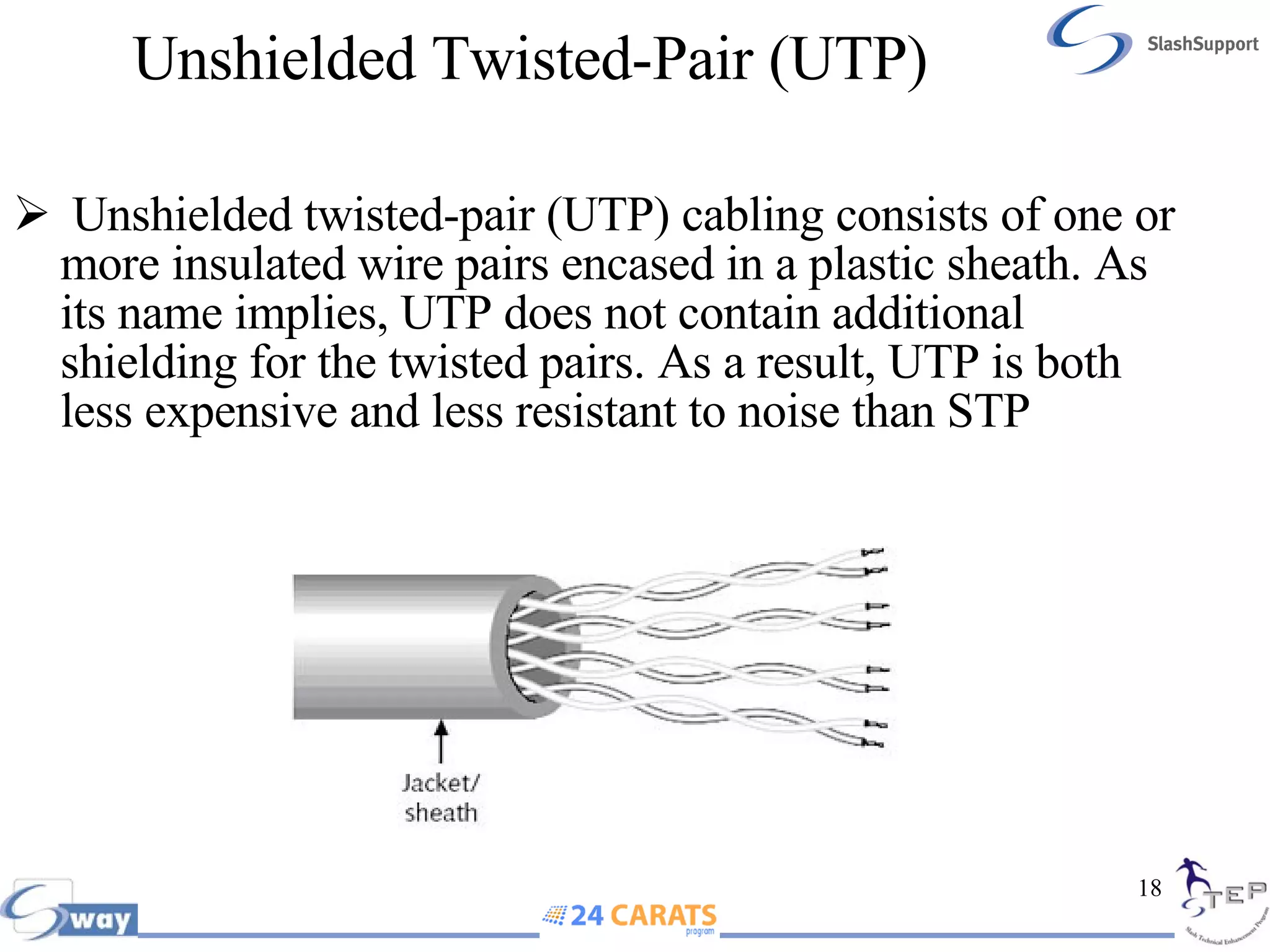
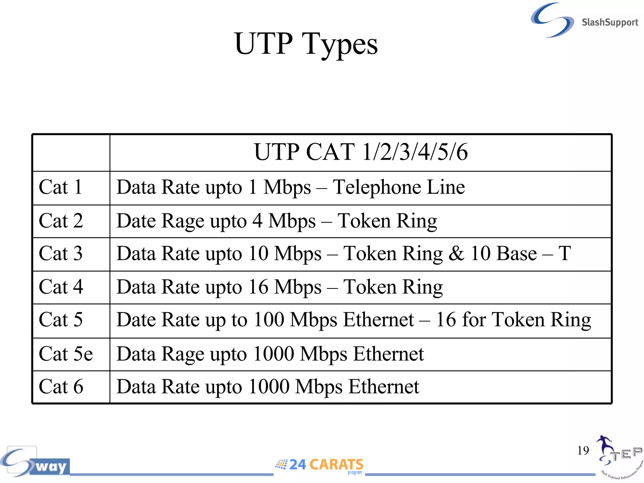
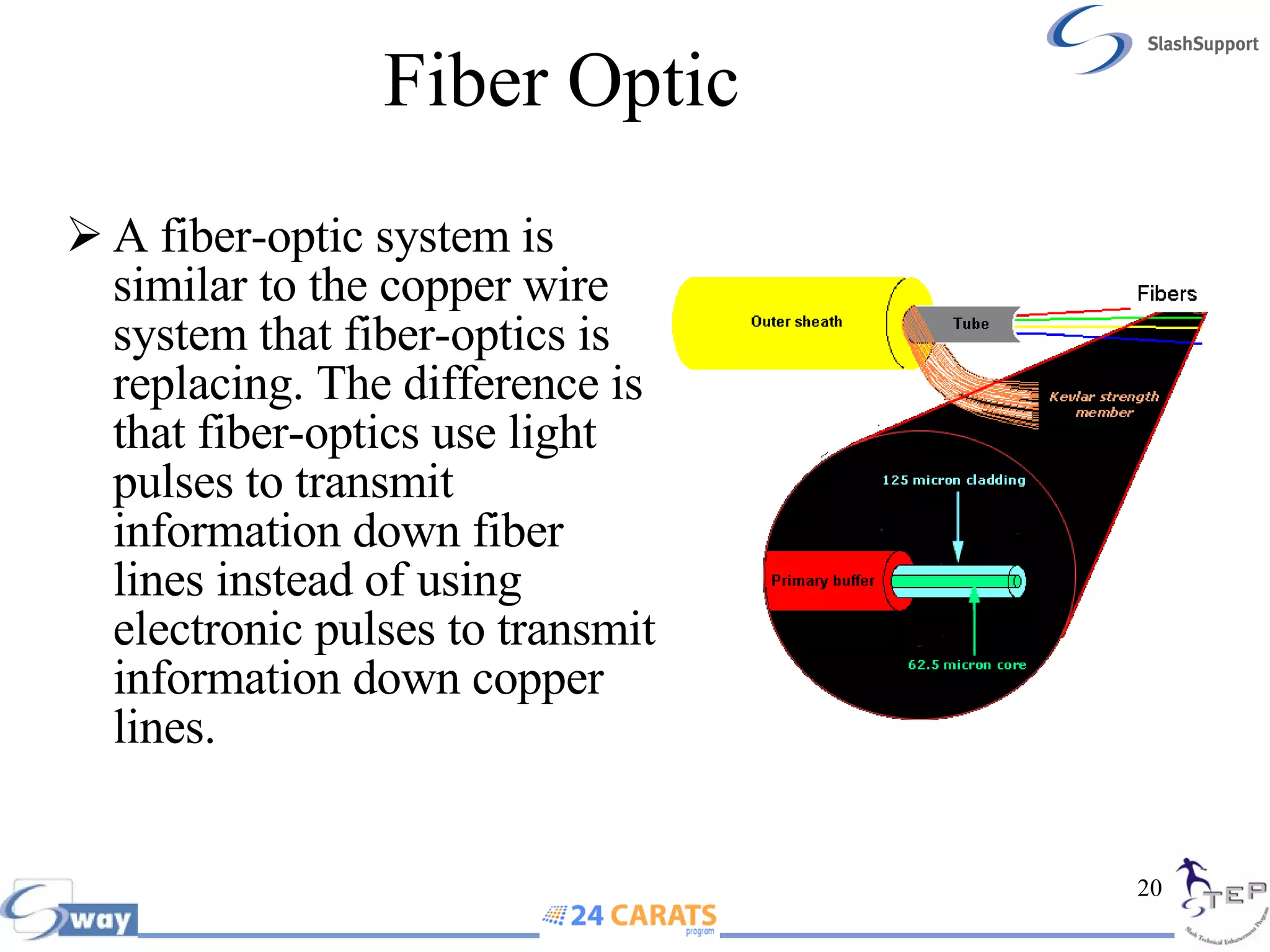
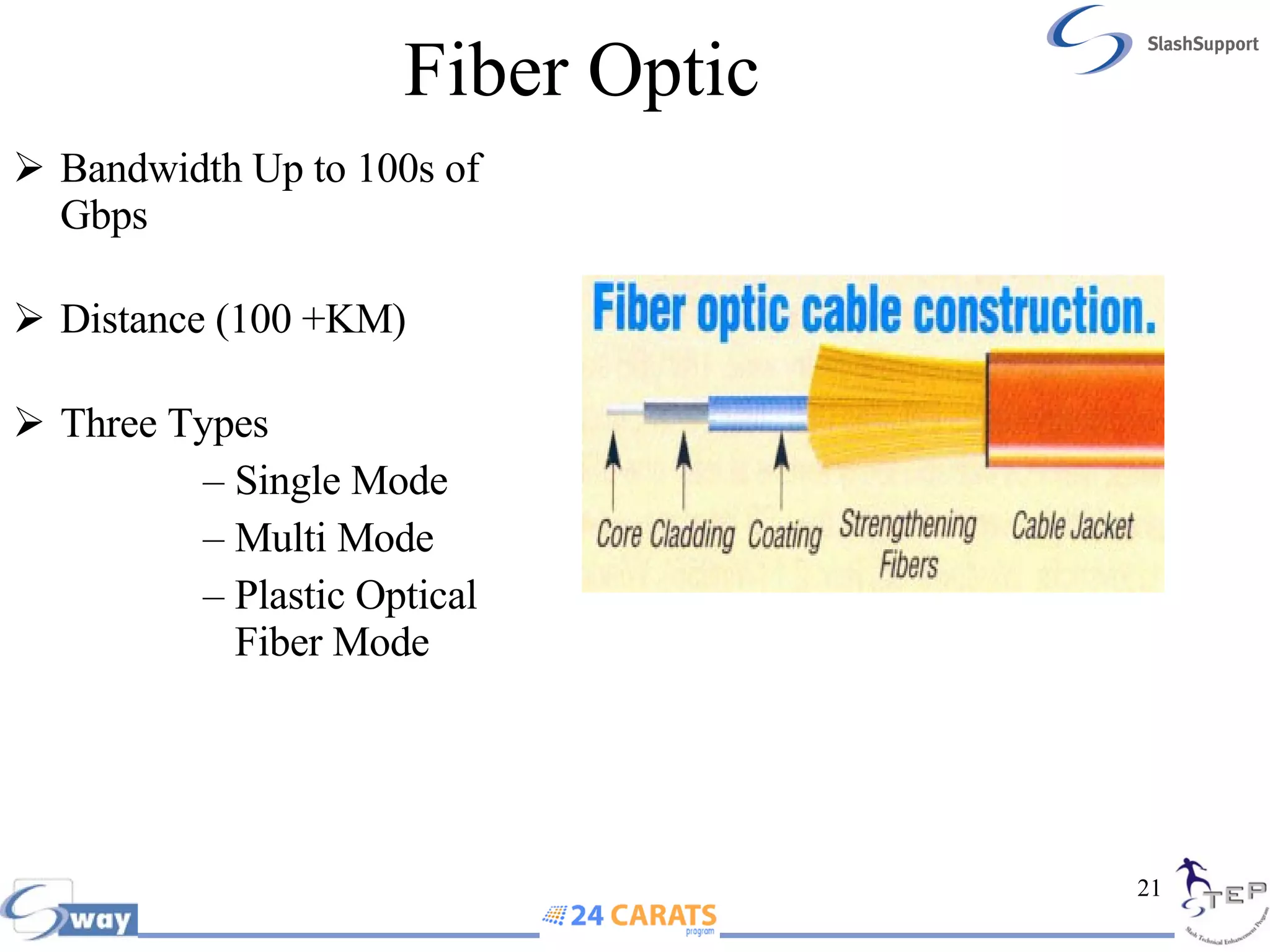
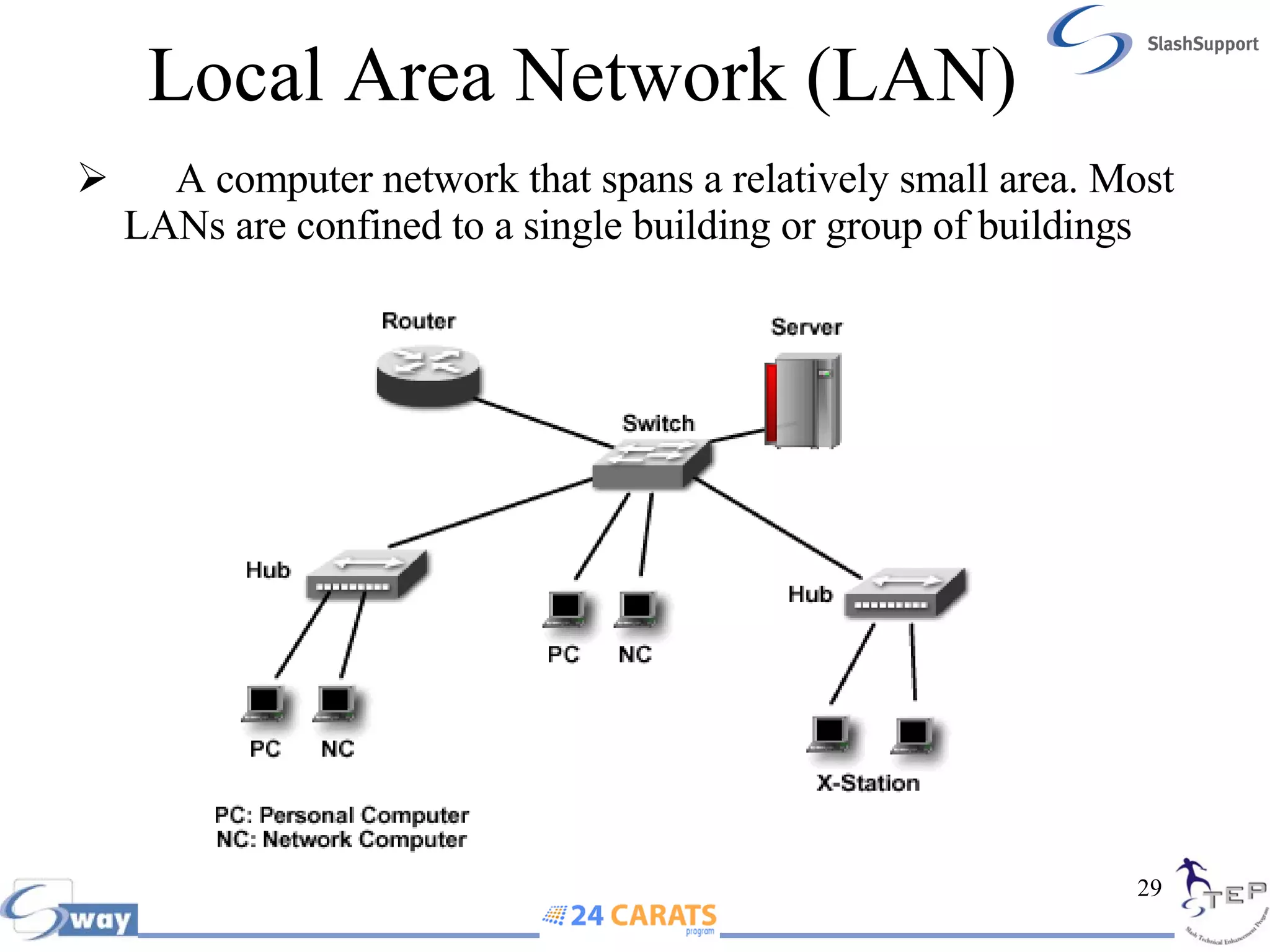
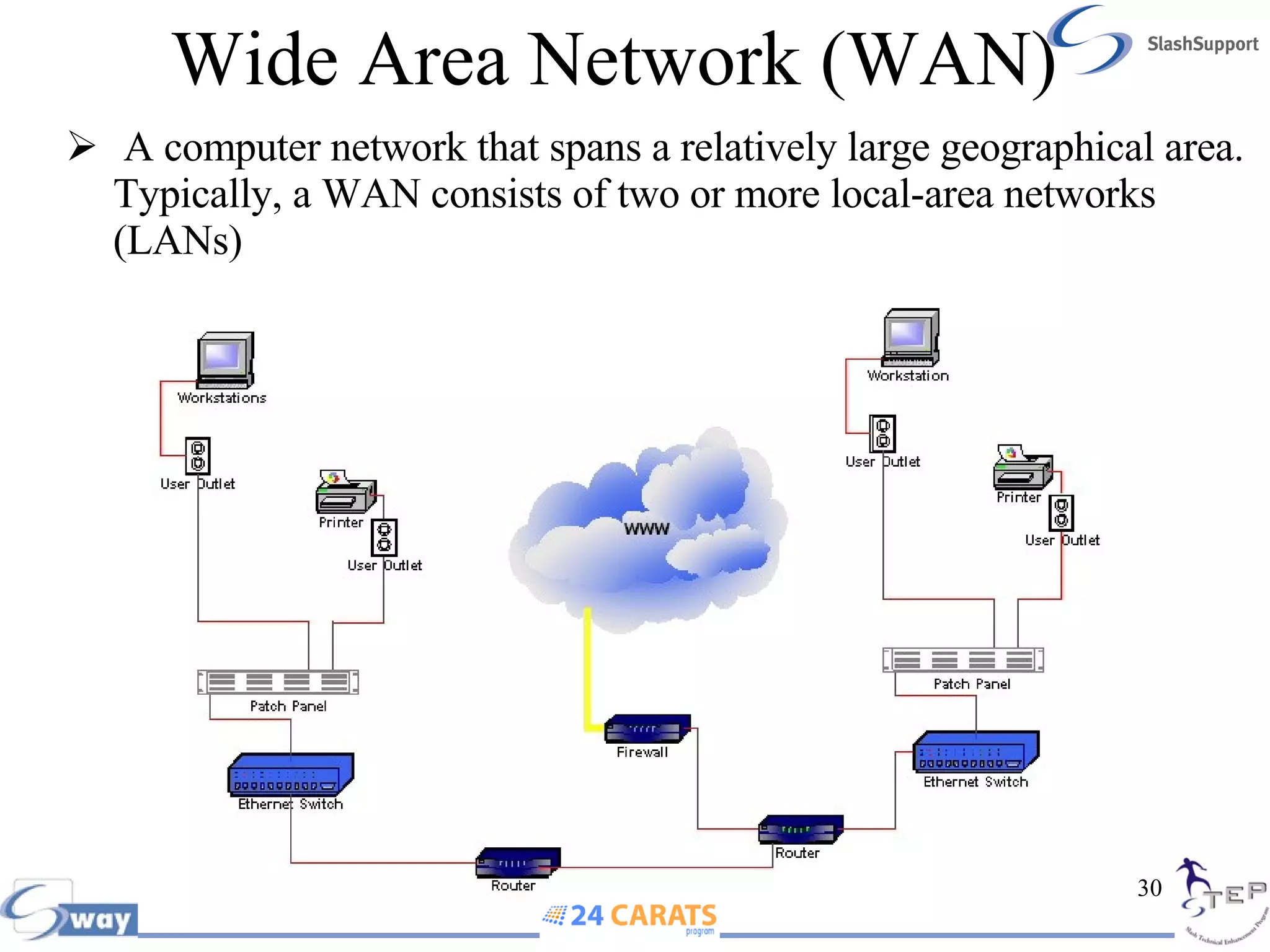
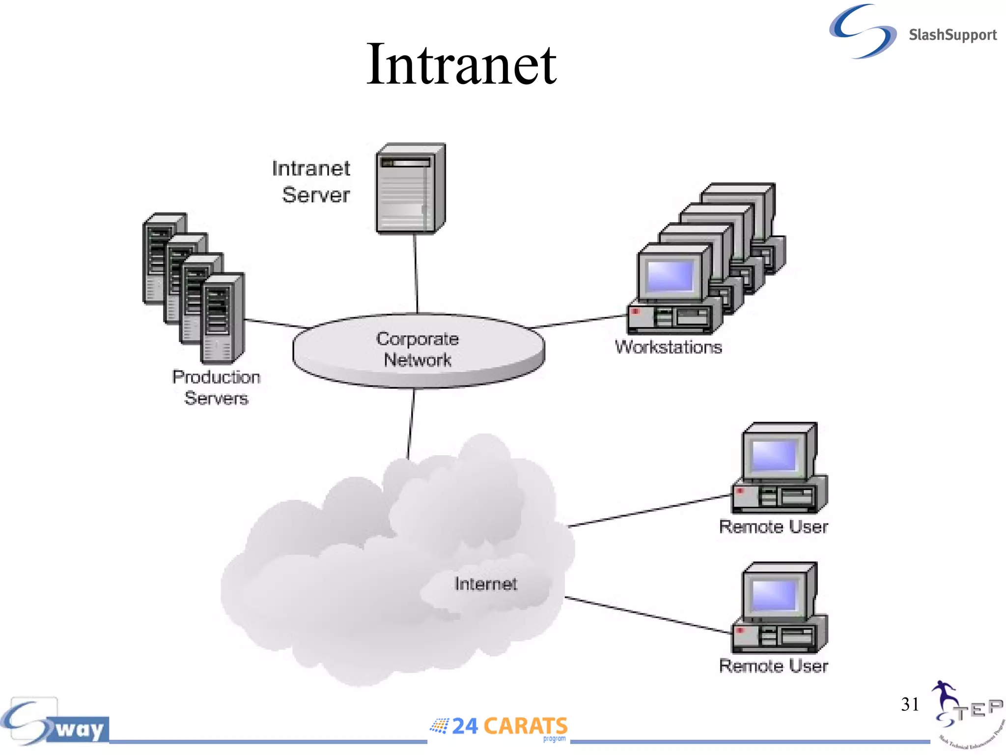
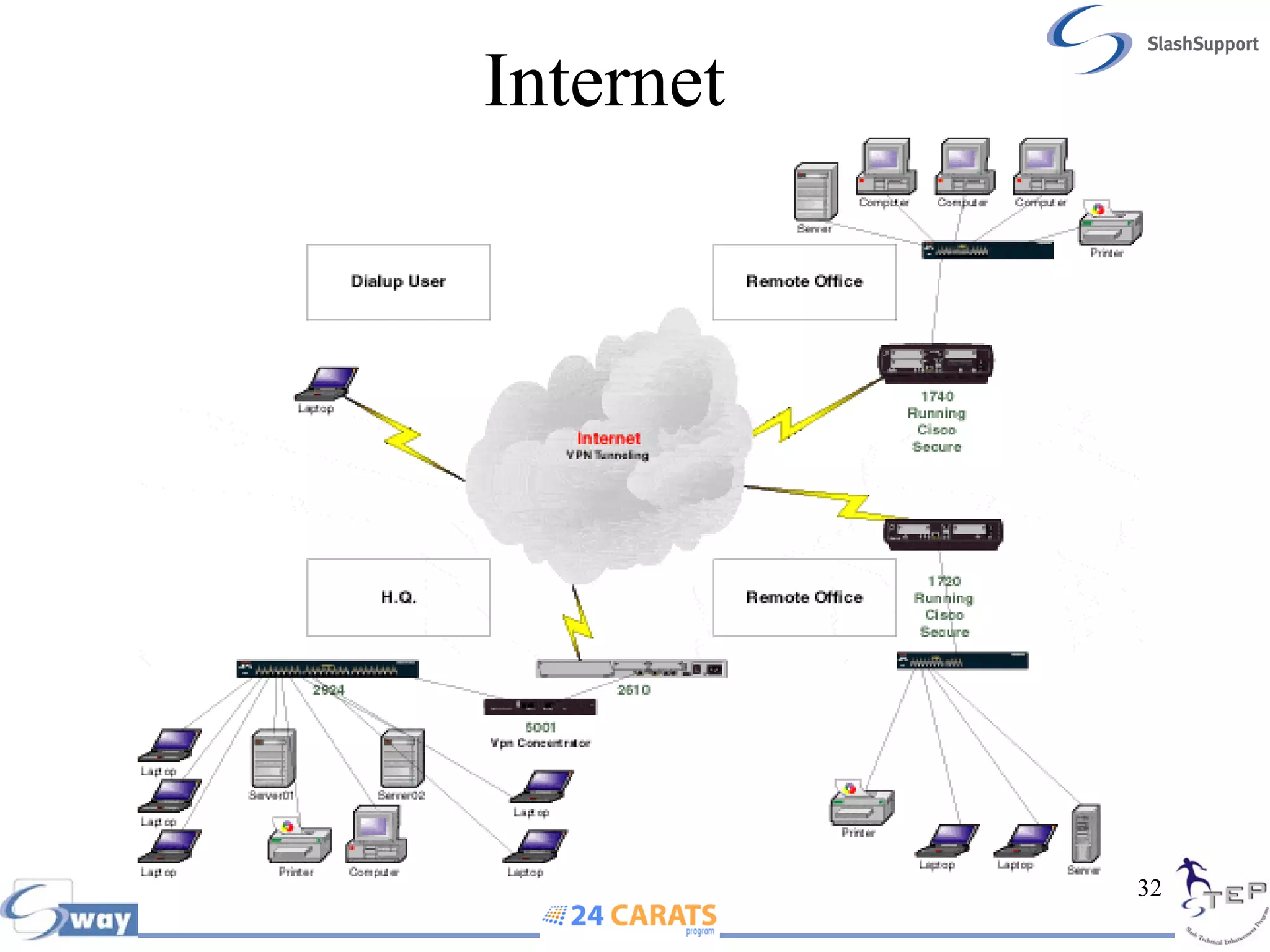
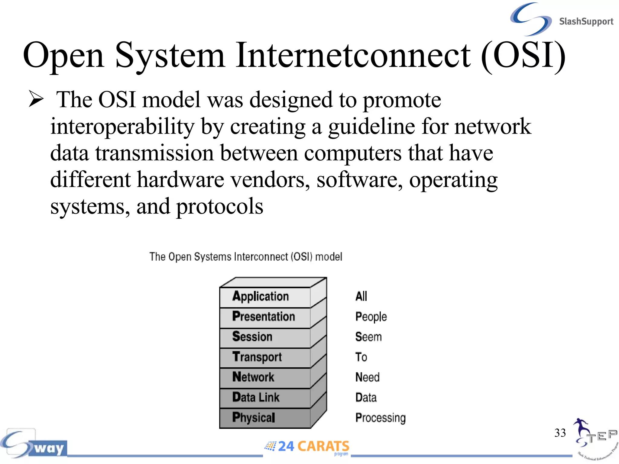
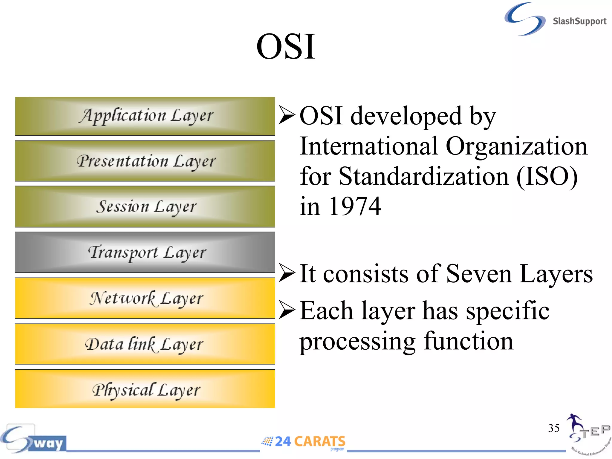
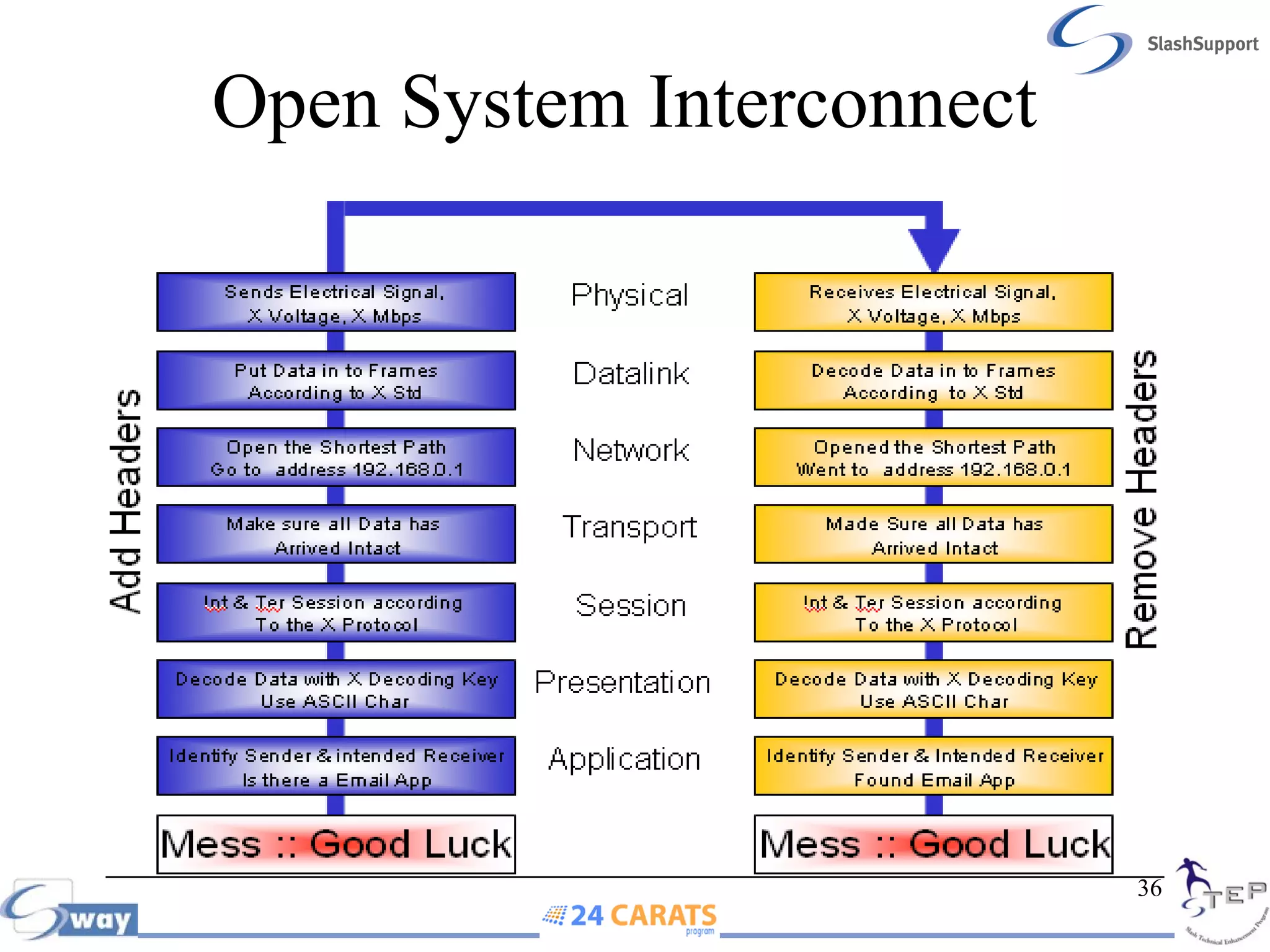
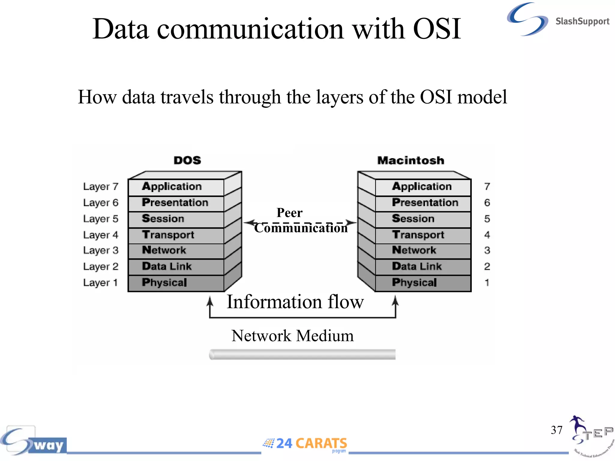
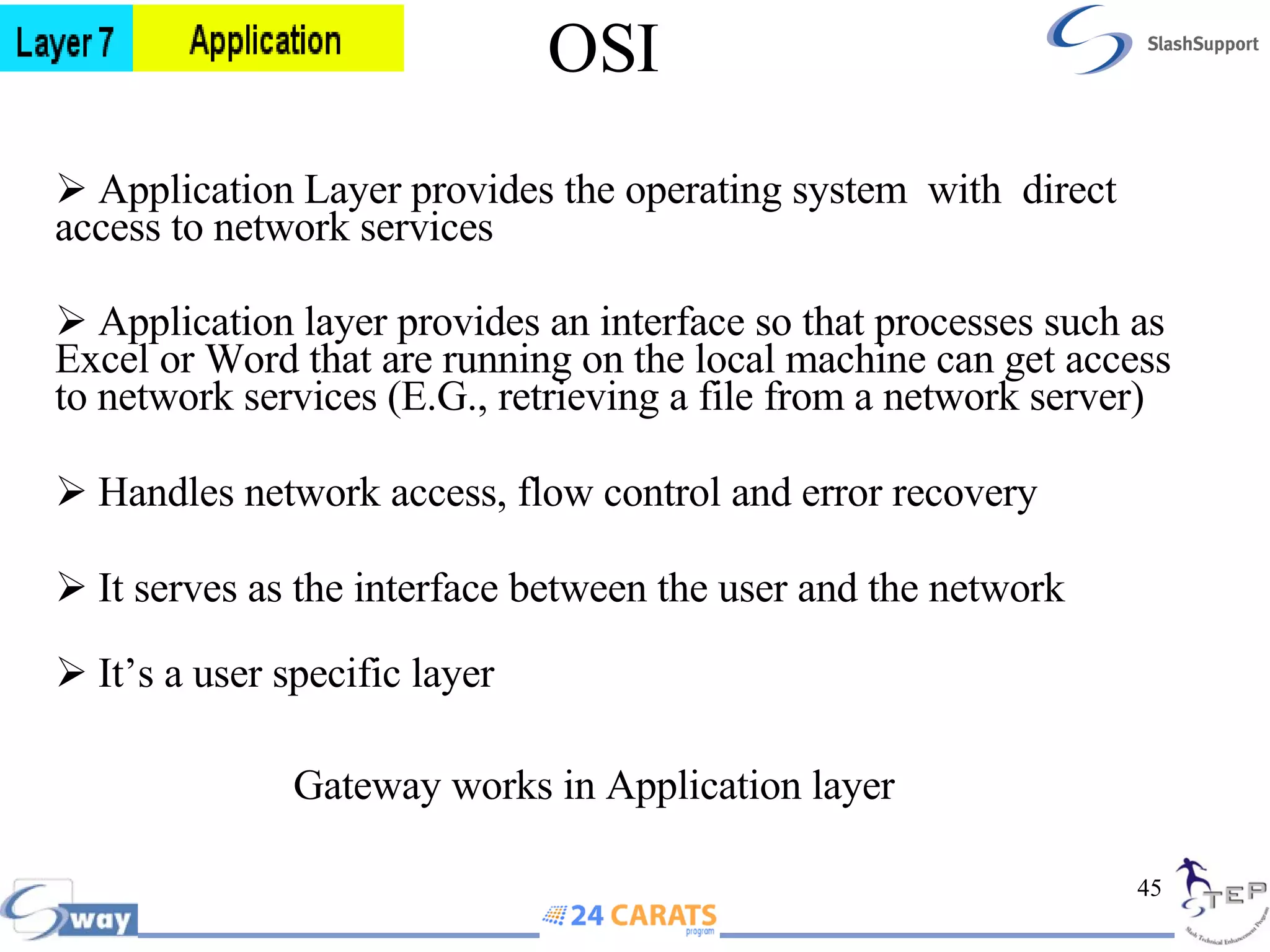
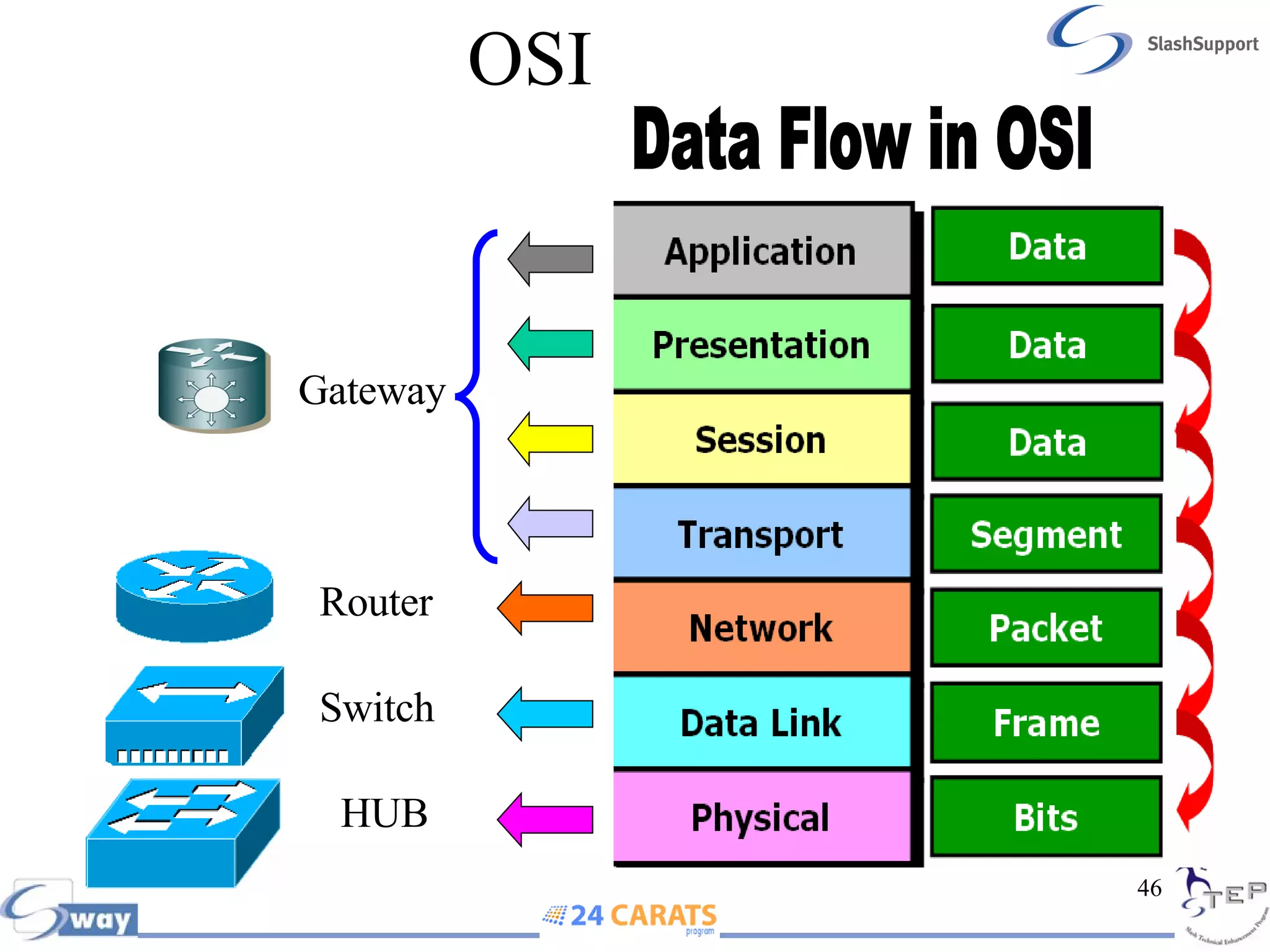
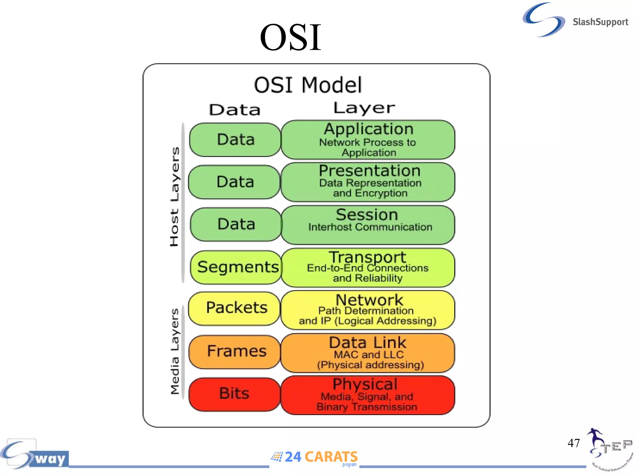
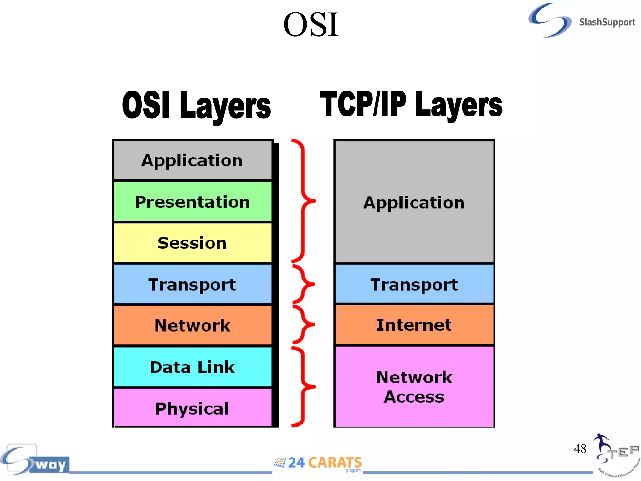


The document discusses various networking concepts including: - Common network topologies like bus, star, ring, and mesh and the characteristics of each. - Twisted pair cabling types like UTP, STP, and fiber optic. - Network devices like hubs, switches, routers, and the differences between LANs, WANs, intranets, and the internet. - The OSI model which defines 7 layers of networking with specific functions at each layer to prepare data for transmission.