Error Detection andCorrection:
• Types of Errors
• Whenever bits flow from one point to another, they are subject to
unpredictable changes because of interference. This interference can
change the shape of the signal.
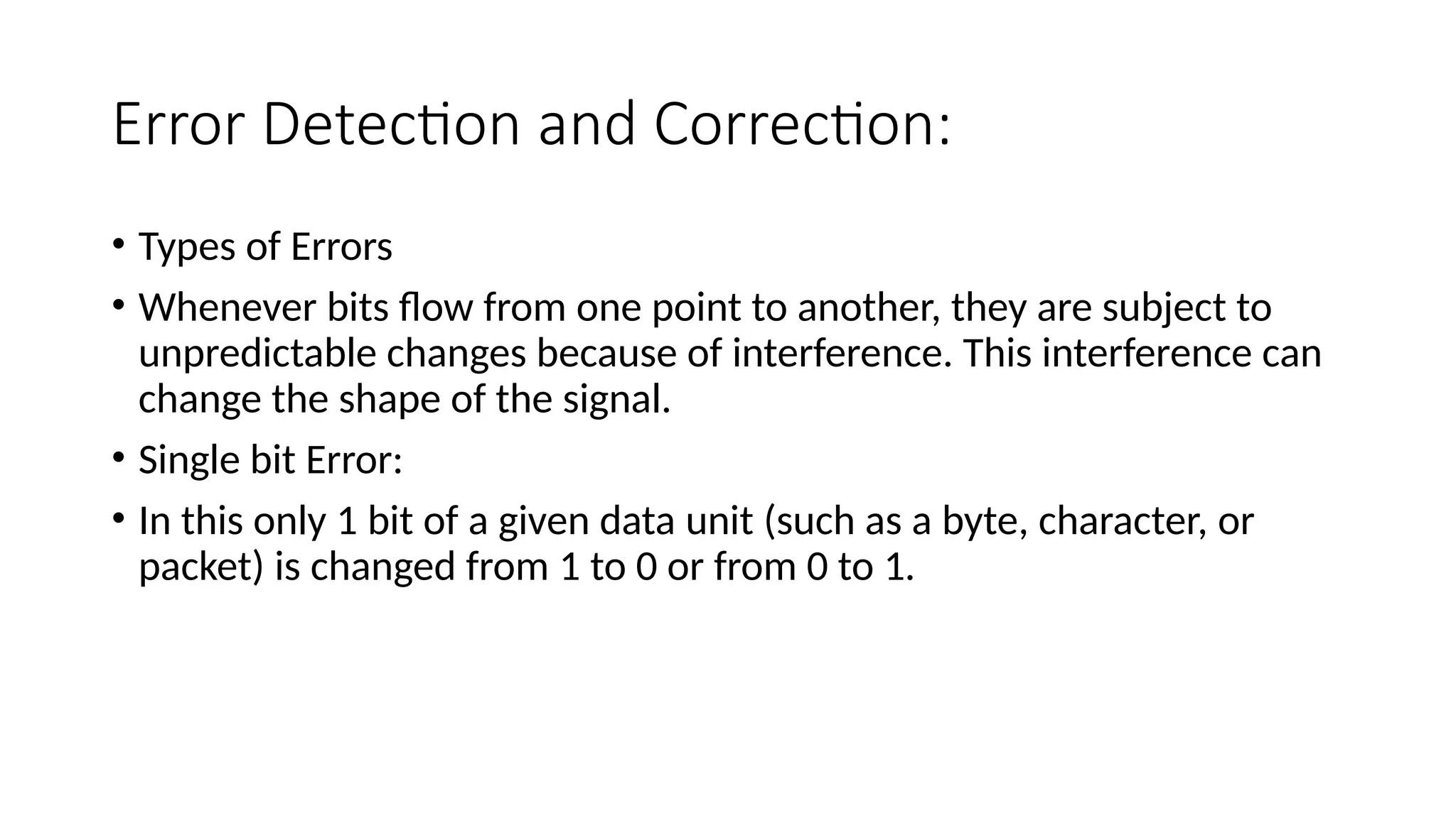
• Single bit Error:
• In this only 1 bit of a given data unit (such as a byte, character, or
packet) is changed from 1 to 0 or from 0 to 1.
TYPES OF ERRORS
•Redundancy:
• The central concept in detecting or correcting errors is redundancy.
• To be able to detect or correct errors, we need to send some extra
bits with our data.
• These redundant bits are added by the sender and removed by the
receiver.
• The number of errors and the size of the message are important
factors.
• There are two coding techniques are commonly available- Block
coding and Convolutional coding
4.
• BLOCK CODING:
•In block coding, the total message is divided into blocks, each of k bits, called data
words.
• There are r redundant bits are added to each block to make the length n = k + r. The
resulting n-bit blocks are called code words.
• Since n > k, the number of possible code words is larger than the number of
possible data words.
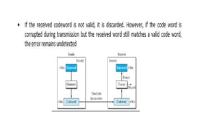
• If the receiver receives an invalid code word, this indicates that the data was
corrupted during transmission.
• The sender creates codewords out of data words by using a generator that applies
the rules and procedures of encoding.
• Each code word sent to the receiver may change during transmission.
• If the received code word is the same as one of the valid code words, the word is
accepted; the corresponding data word is extracted for use.
6.
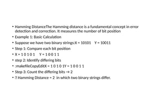
• Hamming DistanceTheHamming distance is a fundamental concept in error
detection and correction. It measures the number of bit position
• Example 1: Basic Calculation
• Suppose we have two binary strings:X = 10101 Y = 10011
• Step 1: Compare each bit position
• X = 1 0 1 0 1 Y = 1 0 0 1 1
• step 2: Identify differing bits
• :makefileCopyEditX = 1 0 1 0 1Y = 1 0 0 1 1
• Step 3: Count the differing bits → 2
• ✅ Hamming Distance = 2 in which two binary strings differ.
7.
• Linear BlockCodes:
• Almost all block codes used today belong to a subset of block codes
called linear block codes.
• In this an exclusive OR (addition modulo-2) of two valid code words
creates another valid code word.
8.
Error cont…
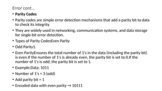
• ParityCodes
• Parity codes are simple error detection mechanisms that add a parity bit to data
to check its integrity.
• They are widely used in networking, communication systems, and data storage
for single-bit error detection.
• Types of Parity CodesEven Parity
• Odd Parity1.
• Even ParityEnsures the total number of 1's in the data (including the parity bit)
is even.If the number of 1's is already even, the parity bit is set to 0.If the
number of 1's is odd, the parity bit is set to 1.
• Example:Data: 1011
• Number of 1's = 3 (odd)
• Add parity bit = 1
• Encoded data with even parity → 10111
9.
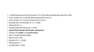
• 2. OddParityEnsures the total number of 1's in the data (including the parity bit) is odd.
• If the number of 1's is already odd, the parity bit is set to 0.
• If the number of 1's is even, the parity bit is set to 1.
• Example:Data: 1011Number of 1's = 3 (odd)
• Add parity bit = 0
• Encoded data with odd parity → 10110
• step-by-Step Example with Sender and Receiver
• Suppose the sender is using Even Parity.
• Step 1: Sender Side (Encoding)
• Data to send: 1101
• Number of 1's = 3 (odd)
• Add parity bit = 1
• encoded data = 11011
10.
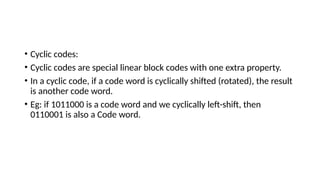
• Cyclic codes:
•Cyclic codes are special linear block codes with one extra property.
• In a cyclic code, if a code word is cyclically shifted (rotated), the result
is another code word.
• Eg: if 1011000 is a code word and we cyclically left-shift, then
0110001 is also a Code word.
11.
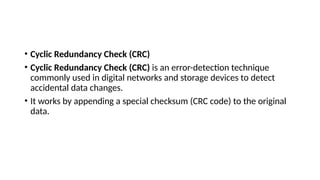
• Cyclic RedundancyCheck (CRC)
• Cyclic Redundancy Check (CRC) is an error-detection technique
commonly used in digital networks and storage devices to detect
accidental data changes.
• It works by appending a special checksum (CRC code) to the original
data.
12.
CRC
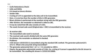
• Cyclic RedundancyCheck:
• LANs and WANs
• It is based on binary division.
• Sender Side:
• A string of n 0’s is appended to the data unit to be transmitted.
• Here, n is one less than the number of bits in CRC generator.
• Binary division is performed of the resultant string with the CRC generator.
• After division, the remainder so obtained is called as CRC.
• It may be noted that CRC also consists of n bits.
• The newly formed code word (Original data + CRC) is transmitted to the receiver.
• At receiver side:
• The transmitted code word is received.
• The received code word is divided with the same CRC generator.
• On division, the remainder so obtained is checked.
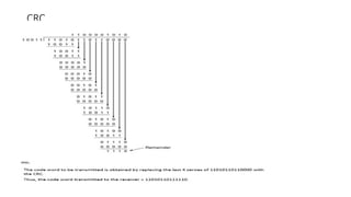
• Problems:
• A bit stream 1101011011 is transmitted using the standard CRC method. The generator polynomial is
x4+x+1. What is the actual bit string transmitted?
• The generator polynomial G(x) = x4 + x + 1 is encoded as 10011.
• Clearly, the generator polynomial consists of 5 bits. So, a string of 4 zeroes is appended to the bit stream to
be transmitted. The resulting bit stream is 11010110110000.
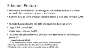
Ethernet Protocol:
• Ethernetis a widely used technology for connecting devices in a wired
network, like computers, printers, and routers.
• It allows data to travel through cables to create a local area network (LAN).
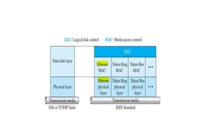
• The IEEE has subdivided the data-link layer into two sub layers:
• logical link control (LLC)
• media access control (MAC).
• IEEE has also created several physical-layer standards for different LAN
protocols
• Logical Link Control (LLC)
The data link control handles framing, flow control, and error control
Framing is handled in both the LLC sub layer and the MAC sub layer.
The LLC provides a single link-layer control protocol for all IEEE LANs.
16.
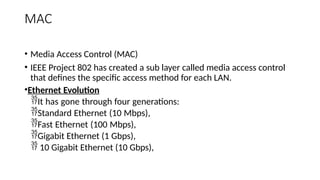
MAC
• Media AccessControl (MAC)
• IEEE Project 802 has created a sub layer called media access control
that defines the specific access method for each LAN.
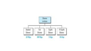
•Ethernet Evolution
It has gone through four generations:
Standard Ethernet (10 Mbps),
Fast Ethernet (100 Mbps),
Gigabit Ethernet (1 Gbps),
10 Gigabit Ethernet (10 Gbps),
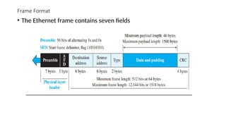
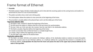
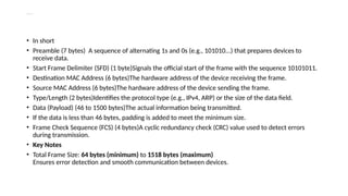
Frame format ofEthernet
• Preamble
• This field contains 7 bytes (56 bits) of alternating 0s and 1s that alert the receiving system to the coming frame and enable it to
synchronize its clock if it’s out of synchronization.
• The pattern provides only an alert and a timing pulse.
• The 56-bit pattern allows the stations to miss some bits at the beginning of the frame.
• The preamble is actually added at the physical layer and is not (formally) part of the frame
•Start frame delimiter (SFD)
This field (1 byte: 10101011) signals the beginning of the frame.
The SFD warns the station or stations that this is the last chance for synchronization.
The last 2 bits are (11)2 and alert the receiver that the next field is the destination address.
This field is actually a flag that defines the beginning of the frame.
It needs to remember that an Ethernet frame is a variable-length frame.
It needs a flag to define the beginning of the frame.
The SFD field is also added at the physical layer.
•Destination address (DA):
This field is six bytes (48 bits) and contains the linklayer address of the destination station or stations to receive the packet.
When the receiver sees its own link-layer address, or a multicast address for a group that the receiver is a member of, or a
broadcast address, it decapsulates the data from the frame and passes the data to the upper layer protocol defined by the
value of the type field.
20.
Cont..
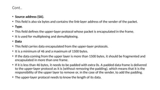
• Source address(SA).
• This field is also six bytes and contains the link-layer address of the sender of the packet.
• Type.
• This field defines the upper-layer protocol whose packet is encapsulated in the frame.
• It is used for multiplexing and demultiplexing.
• Data
• This field carries data encapsulated from the upper-layer protocols.
• It is a minimum of 46 and a maximum of 1500 bytes.
• If the data coming from the upper layer is more than 1500 bytes, it should be fragmented and
encapsulated in more than one frame.
• If it is less than 46 bytes, it needs to be padded with extra 0s. A padded data frame is delivered
to the upper-layer protocol as it is (without removing the padding), which means that it is the
responsibility of the upper layer to remove or, in the case of the sender, to add the padding.
• The upper-layer protocol needs to know the length of its data.
21.
Explanation of EachPart
• In short
• Preamble (7 bytes) A sequence of alternating 1s and 0s (e.g., 101010...) that prepares devices to
receive data.
• Start Frame Delimiter (SFD) (1 byte)Signals the official start of the frame with the sequence 10101011.
• Destination MAC Address (6 bytes)The hardware address of the device receiving the frame.
• Source MAC Address (6 bytes)The hardware address of the device sending the frame.
• Type/Length (2 bytes)Identifies the protocol type (e.g., IPv4, ARP) or the size of the data field.
• Data (Payload) (46 to 1500 bytes)The actual information being transmitted.
• If the data is less than 46 bytes, padding is added to meet the minimum size.
• Frame Check Sequence (FCS) (4 bytes)A cyclic redundancy check (CRC) value used to detect errors
during transmission.
• Key Notes
• Total Frame Size: 64 bytes (minimum) to 1518 bytes (maximum)
Ensures error detection and smooth communication between devices.
23.
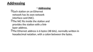
Addressing
• Addressing
Each stationon an Ethernet
network has its own network
interface card (NIC).
The NIC fits inside the station and
provides the station with a link-
layer address.
The Ethernet address is 6 bytes (48 bits), normally written in
hexadecimal notation, with a colon between the bytes.
24.
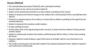
Access Method
• Thestandard Ethernet choose CSMA/CD with 1-persistent method
• Assume station A has a frame to send to station D.
• Station A first should check whether any other station is sending (carrier sense).
• Station A measures the level of energy on the medium (for a short period of time, normally less than
100 μs).
• If there is no signal energy on the medium, it means that no station is sending (or the signal has not
reached station A).
• Station A interprets this situation as idle medium.
• It starts sending its frame.
• On the other hand, if the signal energy level is not zero, it means that the medium is being used by
another station.
• Station A continuously monitors the medium until it becomes idle for 100 μs. It then starts sending
the frame.
• However, station A needs to keep a copy of the frame in its buffer until it is sure that there is no
collision.
• The medium sensing does not stop after station A has started sending the frame. Station A needs to
send and receive continuously.
25.
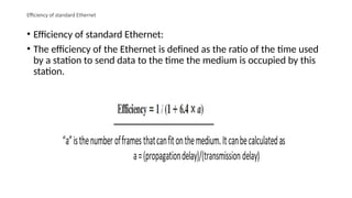
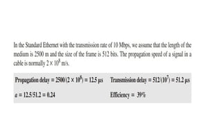
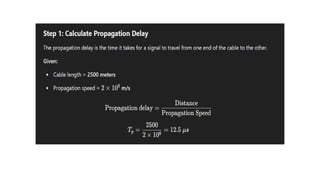
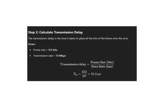
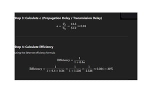
Efficiency of standardEthernet
• Efficiency of standard Ethernet:
• The efficiency of the Ethernet is defined as the ratio of the time used
by a station to send data to the time the medium is occupied by this
station.
30.
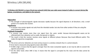
Wireless LAN (WLAN)
•AWireless LAN (WLAN) is a type of local area network (LAN) that uses radio waves instead of cables to connect devices like
laptops, smartphones, and tablets to the network.
•Attenuation
The strength of electromagnetic signals decreases rapidly because the signal disperses in all directions; only a small
portion of it reaches the receiver.
•Interference
A receiver may receive signals not only from the intended sender, but also from other senders if they are using the
same frequency band.
•Multipath Propagation
A receiver may receive more than one signal from the same sender because electromagnetic waves can be
reflected back from obstacles such as walls, the ground, or objects.
The result is that the receiver receives some signals at different phases (because they travel different paths). This
makes the signal less recognizable
•Error
The errors and error detection are more serious issues in a wireless network than in a wired network.
Error level is measured using signal-to-noise ratio (SNR).
If SNR is high, it means that the signal is stronger than the noise (unwanted signal), so we may be able to convert the
signal to actual data.
On the other hand, when SNR is low, it means that the signal is corrupted by the noise and the data cannot be
recovered.
31.
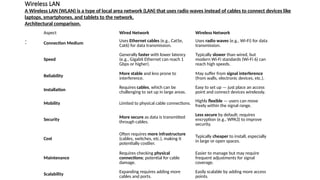
Wireless LAN
A WirelessLAN (WLAN) is a type of local area network (LAN) that uses radio waves instead of cables to connect devices like
laptops, smartphones, and tablets to the network.
Architectural comparison.
:
Aspect Wired Network Wireless Network
Connection Medium
Uses Ethernet cables (e.g., Cat5e,
Cat6) for data transmission.
Uses radio waves (e.g., Wi-Fi) for data
transmission.
Speed
Generally faster with lower latency
(e.g., Gigabit Ethernet can reach 1
Gbps or higher).
Typically slower than wired, but
modern Wi-Fi standards (Wi-Fi 6) can
reach high speeds.
Reliability
More stable and less prone to
interference.
May suffer from signal interference
(from walls, electronic devices, etc.).
Installation
Requires cables, which can be
challenging to set up in large areas.
Easy to set up — just place an access
point and connect devices wirelessly.
Mobility Limited to physical cable connections.
Highly flexible — users can move
freely within the signal range.
Security
More secure as data is transmitted
through cables.
Less secure by default; requires
encryption (e.g., WPA3) to improve
security.
Cost
Often requires more infrastructure
(cables, switches, etc.), making it
potentially costlier.
Typically cheaper to install, especially
in large or open spaces.
Maintenance
Requires checking physical
connections; potential for cable
damage.
Easier to manage but may require
frequent adjustments for signal
coverage.
Scalability
Expanding requires adding more
cables and ports.
Easily scalable by adding more access
points.
32.
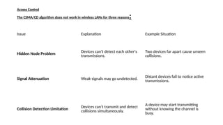
Access Control
The CSMA/CDalgorithm does not work in wireless LANs for three reasons:
Issue Explanation Example Situation
Hidden Node Problem Devices can’t detect each other's
transmissions.
Two devices far apart cause unseen
collisions.
Signal Attenuation Weak signals may go undetected. Distant devices fail to notice active
transmissions.
Collision Detection Limitation Devices can’t transmit and detect
collisions simultaneously.
A device may start transmitting
without knowing the channel is
busy.
33.
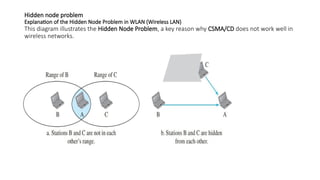
Hidden node problem
Explanationof the Hidden Node Problem in WLAN (Wireless LAN)
This diagram illustrates the Hidden Node Problem, a key reason why CSMA/CD does not work well in
wireless networks.
34.
Cont…
Diagram (a):
Stations Band C are not in each other's range
• Device B and Device C are both within range of Device A, but B and C
cannot "see" each other because they are too far apart.
• This creates a scenario where:
Device B can send data to Device A.
Device C can send data to Device A.
However, Device B and Device C are unaware of each other's
transmissions.
• Result: If both B and C send data at the same time, a collision will
occur at Device A — yet neither B nor C realizes it happened.
35.
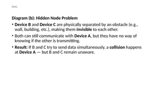
Cont..
Diagram (b): HiddenNode Problem
• Device B and Device C are physically separated by an obstacle (e.g.,
wall, building, etc.), making them invisible to each other.
• Both can still communicate with Device A, but they have no way of
knowing if the other is transmitting.
• Result: If B and C try to send data simultaneously, a collision happens
at Device A — but B and C remain unaware.
36.
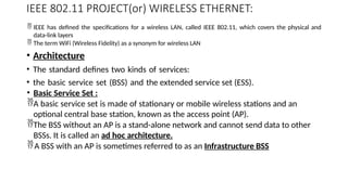
IEEE 802.11 PROJECT(or)WIRELESS ETHERNET:
IEEE has defined the specifications for a wireless LAN, called IEEE 802.11, which covers the physical and
data-link layers
The term WiFi (Wireless Fidelity) as a synonym for wireless LAN
• Architecture
• The standard defines two kinds of services:
• the basic service set (BSS) and the extended service set (ESS).
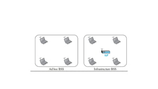
• Basic Service Set :
A basic service set is made of stationary or mobile wireless stations and an
optional central base station, known as the access point (AP).
The BSS without an AP is a stand-alone network and cannot send data to other
BSSs. It is called an ad hoc architecture.
A BSS with an AP is sometimes referred to as an Infrastructure BSS
38.
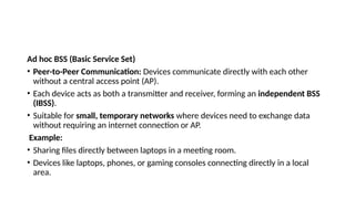
Ad hoc BSS(Basic Service Set)
• Peer-to-Peer Communication: Devices communicate directly with each other
without a central access point (AP).
• Each device acts as both a transmitter and receiver, forming an independent BSS
(IBSS).
• Suitable for small, temporary networks where devices need to exchange data
without requiring an internet connection or AP.
Example:
• Sharing files directly between laptops in a meeting room.
• Devices like laptops, phones, or gaming consoles connecting directly in a local
area.
39.
Cont..
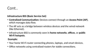
Infrastructure BSS (BasicService Set)
• Centralized Communication: Devices connect through an Access Point (AP),
which manages data flow.
• The AP acts as a bridge between wireless devices and the wired network
(like Ethernet).
• Infrastructure BSS is commonly seen in home networks, offices, or public
Wi-Fi hotspots.
Example:
• Your home Wi-Fi router connecting phones, laptops, and smart devices.
• Office networks using centralized routers for stable connections.
40.
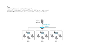
Ess
•Extended Service Set
Anextended service set (ESS) is made up of two or more BSSs with APs.
In this case, the BSSs are connected through a distribution system,
which is a wired or a wireless network.
The distribution system connects the APs in the BSSs.
IEEE 802.11 does not restrict the distribution system; it can be any IEEE
LAN such as an Ethernet.
The mobile stations are normal stations inside a BSS.
The stationary stations are AP stations that are part of a wired LAN.
41.
Ess
Devices within aBSS communicate directly through their respective AP.
If a device in BSS 1 wants to communicate with a device in BSS 3, the data travels:
From the device → To the AP in BSS 1 → Through the Distribution System → To the AP in BSS 3 → To the target device.
The Distribution System acts like a backbone network to ensure smooth data flow between multiple BSS regions
42.
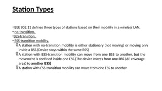
Station Types
•IEEE 802.11defines three types of stations based on their mobility in a wireless LAN:
• no-transition,
•BSS-transition,
• ESS-transition mobility.
A station with no-transition mobility is either stationary (not moving) or moving only
inside a BSS.(Device stays within the same BSS)
A station with BSS-transition mobility can move from one BSS to another, but the
movement is confined inside one ESS.(The device moves from one BSS (AP coverage
area) to another BSS)
A station with ESS-transition mobility can move from one ESS to another
43.
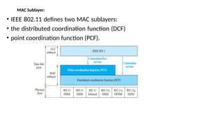
MAC Sublayer:
• IEEE802.11 defines two MAC sublayers:
• the distributed coordination function (DCF)
• point coordination function (PCF).
44.
Cont..
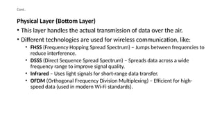
Physical Layer (BottomLayer)
• This layer handles the actual transmission of data over the air.
• Different technologies are used for wireless communication, like:
• FHSS (Frequency Hopping Spread Spectrum) – Jumps between frequencies to
reduce interference.
• DSSS (Direct Sequence Spread Spectrum) – Spreads data across a wide
frequency range to improve signal quality.
• Infrared – Uses light signals for short-range data transfer.
• OFDM (Orthogonal Frequency Division Multiplexing) – Efficient for high-
speed data (used in modern Wi-Fi standards).
45.
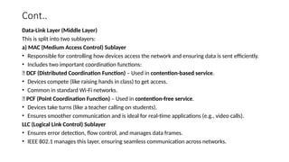
Cont..
Data-Link Layer (MiddleLayer)
This is split into two sublayers:
a) MAC (Medium Access Control) Sublayer
• Responsible for controlling how devices access the network and ensuring data is sent efficiently.
• Includes two important coordination functions:
✅ DCF (Distributed Coordination Function) – Used in contention-based service.
• Devices compete (like raising hands in class) to get access.
• Common in standard Wi-Fi networks.
✅ PCF (Point Coordination Function) – Used in contention-free service.
• Devices take turns (like a teacher calling on students).
• Ensures smoother communication and is ideal for real-time applications (e.g., video calls).
LLC (Logical Link Control) Sublayer
• Ensures error detection, flow control, and manages data frames.
• IEEE 802.1 manages this layer, ensuring seamless communication across networks.
46.
Cont..
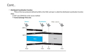
• Distributed CoordinationFunction:
One of the two protocols defined by IEEE at the MAC sub layer is called the distributed coordination function
(DCF).
DCF uses CSMA/CA as the access method
Frame Exchange Time Line:
47.
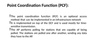
Point Coordination Function(PCF):
The point coordination function (PCF) is an optional access
method that can be implemented in an infrastructure network
It is implemented on top of the DCF and is used mostly for time-
sensitive transmission.
The AP performs polling for stations that are capable of being
polled. The stations are polled one after another, sending any data
they have to the AP.
48.
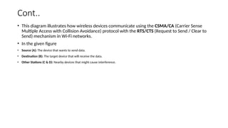
Cont..
• This diagramillustrates how wireless devices communicate using the CSMA/CA (Carrier Sense
Multiple Access with Collision Avoidance) protocol with the RTS/CTS (Request to Send / Clear to
Send) mechanism in Wi-Fi networks.
• In the given figure
• Source (A): The device that wants to send data.
• Destination (B): The target device that will receive the data.
• Other Stations (C & D): Nearby devices that might cause interference.
49.
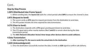
Cont..
Step-by-Step Process
1.DIFS (DistributedInter-Frame Space):
1. Before sending data, the Source (A) waits for a short period called DIFS to ensure the channel is clear.
2.RTS (Request to Send):
1. The source sends an RTS signal to request permission from the destination to send data.
2. This RTS packet includes the time required for data transmission.
3.CTS (Clear to Send):
1. The destination responds with a CTS signal, granting permission to send data.
2. This CTS signal alerts other nearby stations (like C and D) to remain silent during the data
transmission period.
3. The NAV (Network Allocation Vector) timer keeps other devices silent to avoid collisions.
4.Data Transmission:
1. After receiving CTS, the source sends the actual data to the destination.
5.ACK (Acknowledgment):
1. Once the destination successfully receives the data, it sends an ACK signal to confirm safe delivery.
50.
Cont..
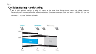
•Collision During Handshaking
Two or more stations may try to send RTS frames at the same time. These control frames may collide. However,
because there is no mechanism for collision detection, the sender assumes there has been a collision if it has not
received a CTS frame from the receiver.
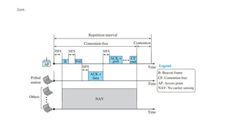
To give priorityto PCF over DCF, another interframe space, PIFS, has
been defined.
PIFS (PCF IFS) is shorter than DIFS.
Due to the priority of PCF over DCF, stations that only use DCF may
not gain access to the medium.
To prevent this, a repetition interval has been designed to cover
both contention-free PCF and contention-based DCF traffic. The
repetition interval, which is repeated continuously, starts with a
special control frame, called a beacon frame.
When the stations hear the beacon frame, they start their NAV for
the duration of the contention-free period of the repetition interval
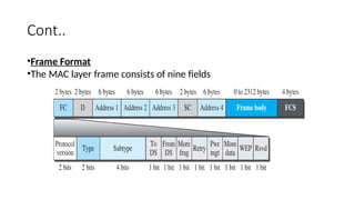
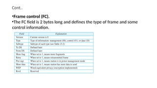
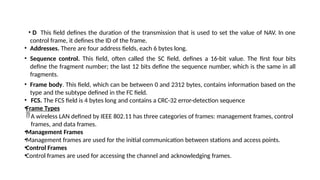
• D Thisfield defines the duration of the transmission that is used to set the value of NAV. In one
control frame, it defines the ID of the frame.
• Addresses. There are four address fields, each 6 bytes long.
• Sequence control. This field, often called the SC field, defines a 16-bit value. The first four bits
define the fragment number; the last 12 bits define the sequence number, which is the same in all
fragments.
• Frame body. This field, which can be between 0 and 2312 bytes, contains information based on the
type and the subtype defined in the FC field.
• FCS. The FCS field is 4 bytes long and contains a CRC-32 error-detection sequence
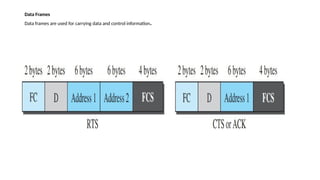
•Frame Types
A wireless LAN defined by IEEE 802.11 has three categories of frames: management frames, control
frames, and data frames.
•Management Frames
•Management frames are used for the initial communication between stations and access points.
•Control Frames
•Control frames are used for accessing the channel and acknowledging frames.
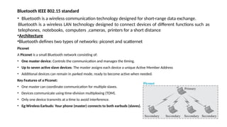
Bluetooth IEEE 802.15standard
• Bluetooth is a wireless communication technology designed for short-range data exchange.
Bluetooth is a wireless LAN technology designed to connect devices of different functions such as
telephones, notebooks, computers ,cameras, printers for a short distance
•Architecture
•Bluetooth defines two types of networks: piconet and scatternet
Piconet
A Piconet is a small Bluetooth network consisting of:
• One master device: Controls the communication and manages the timing.
• Up to seven active slave devices: The master assigns each device a unique Active Member Address
• Additional devices can remain in parked mode, ready to become active when needed.
Key Features of a Piconet:
• One master can coordinate communication for multiple slaves.
• Devices communicate using time-division multiplexing (TDM).
• Only one device transmits at a time to avoid interference.
• Eg:Wireless Earbuds: Your phone (master) connects to both earbuds (slaves).
58.
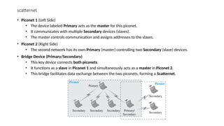
scatternet
• Piconet 1(Left Side)
• The device labeled Primary acts as the master for this piconet.
• It communicates with multiple Secondary devices (slaves).
• The master controls communication and assigns addresses to the slaves.
• Piconet 2 (Right Side)
• The second network has its own Primary (master) controlling two Secondary (slave) devices.
• Bridge Device (Primary/Secondary)
• This key device connects both piconets.
• It functions as a slave in Piconet 1 and simultaneously acts as a master in Piconet 2.
• This bridge facilitates data exchange between the two piconets, forming a Scatternet.
59.
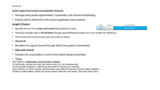
Bluetooth Layers
L2CAP (LogicalLink Control and Adaptation Protocol)
• Manages data packet segmentation, reassembly, and channel multiplexing.
• Ensures data is delivered to the correct application layer protocol.
Length (2 bytes)
• Specifies the size of the Data and Control field (payload) in bytes.
• Maximum possible value is 65,535 bytes (though typical Bluetooth packets are much smaller for efficiency).
• This ensures the receiver knows how much data to expect.
• Channel ID
• Identifies the logical channel through which the packet is transmitted.
• Data and control
• Contains the actual data or control information being transmitted.
• TDMA
•DD-TDMA is a half-duplex communication method.
•In half-duplex, devices can send and receive data, but not simultaneously.
•Communication happens in alternating time slots for sending and receiving.
•Each direction of communication (send/receive) uses different frequency hops for better reliability.
•Similar to walkie-talkies, where one person speaks while the other listens, then they switch roles
60.
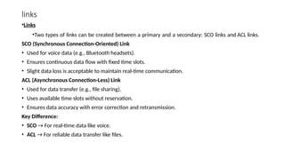
links
•Links
•Two types oflinks can be created between a primary and a secondary: SCO links and ACL links.
SCO (Synchronous Connection-Oriented) Link
• Used for voice data (e.g., Bluetooth headsets).
• Ensures continuous data flow with fixed time slots.
• Slight data loss is acceptable to maintain real-time communication.
ACL (Asynchronous Connection-Less) Link
• Used for data transfer (e.g., file sharing).
• Uses available time slots without reservation.
• Ensures data accuracy with error correction and retransmission.
Key Difference:
• SCO → For real-time data like voice.
• ACL → For reliable data transfer like files.
61.
Frame format
1.Access Code(72 bits)
•Used for synchronization and identifying the intended receiver.
2.Header (54 bits)
•Contains key control information for managing the Bluetooth connection.
•Repeated 3 times for reliability.
•Divided into several parts:
•Address (3 bits): Identifies the device within the network (e.g., primary or secondary).
•Type (4 bits): Describes the type of packet being sent (e.g., data or control).
•F (1 bit): Flow control bit (manages data flow).
•A (1 bit): Acknowledgment bit (confirms receipt of previous data).
•S (1 bit): Sequence number bit (tracks the order of packets).
•HEC (8 bits): Header Error Check (used to detect errors in the header).
3.Payload (0 to N bits)
•The actual data being sent.
•The size can vary based on the number of time slots:
•1-slot frame: 240 bits
•3-slot frame: 1490 bits
•5-slot frame: 2740 bits
Summary:
•Access Code helps sync devices.
•Header manages data control and error detection.
•Payload carries the actual data, and its size varies based on the number of slots.
•Bluetooth uses a 2.4-GHz ISM(Industrial, Scientific, and Medical) band divided into 79 channels of 1 MHz each.
• FHSS Bluetooth uses the frequency-hopping spread spectrum (FHSS) method in the physical layer to avoid interference from other
devices or other networks
• Modulation To transform bits to a signal, Bluetooth uses a sophisticated version of FSK, called GFSK (FSK with Gaussian bandwidth
filtering)
62.
Flow and ErrorControl Protocols:
•Flow and Error Control Protocols:
•The Data Link Control (DLC) protocol can be either connectionless or connection-oriented.
•Connectionless Protocol:
In a connectionless protocol, frames are sent from one node to the next without any relationship between the frames; each frame is independent.
•Connection-Oriented Protocol
In a connection-oriented protocol, a logical connection should first be established between the two nodes (setup phase).
After all frames that are somehow related to each other are transmitted (transfer phase), the logical connection is terminated (teardown phase)
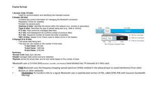
Simple Protocol
•Network Layer at the Sender creates packets of data to send.
•These packets are passed down to the Data Link Layer, which wraps them into frames for transmission.
•The frames travel across the communication channel to the receiving node.
•On the receiving side, the Data Link Layer extracts the data from the received frames and passes the original packets up to the Network Layer
63.
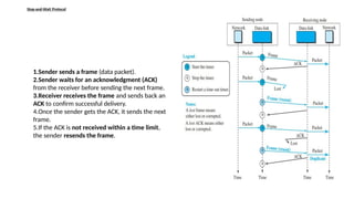
Stop-and-Wait Protocol
1.Sender sendsa frame (data packet).
2.Sender waits for an acknowledgment (ACK)
from the receiver before sending the next frame.
3.Receiver receives the frame and sends back an
ACK to confirm successful delivery.
4.Once the sender gets the ACK, it sends the next
frame.
5.If the ACK is not received within a time limit,
the sender resends the frame.
64.
HDLC
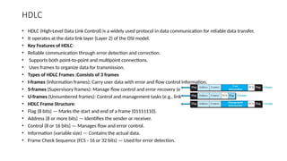
• HDLC (High-LevelData Link Control) is a widely used protocol in data communication for reliable data transfer.
• It operates at the data link layer (Layer 2) of the OSI model.
• Key Features of HDLC:
• Reliable communication through error detection and correction.
• Supports both point-to-point and multipoint connections.
• Uses frames to organize data for transmission.
• Types of HDLC Frames :Consists of 3 frames
• I-frames (Information frames): Carry user data with error and flow control information.
• S-frames (Supervisory frames): Manage flow control and error recovery (e.g., ACK).
• U-frames (Unnumbered frames): Control and management tasks (e.g., link setup).
• HDLC Frame Structure:
• Flag (8 bits) — Marks the start and end of a frame (01111110).
• Address (8 or more bits) — Identifies the sender or receiver.
• Control (8 or 16 bits) — Manages flow and error control.
• Information (variable size) — Contains the actual data.
• Frame Check Sequence (FCS - 16 or 32 bits) — Used for error detection.
65.
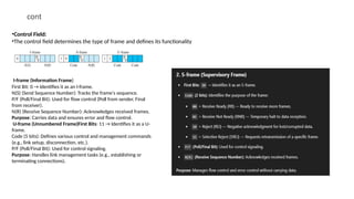
cont
•Control Field:
•The controlfield determines the type of frame and defines its functionality
I-frame (Information Frame)
First Bit: 0 → Identifies it as an I-frame.
N(S) (Send Sequence Number): Tracks the frame's sequence.
P/F (Poll/Final Bit): Used for flow control (Poll from sender, Final
from receiver).
N(R) (Receive Sequence Number): Acknowledges received frames.
Purpose: Carries data and ensures error and flow control.
U-frame (Unnumbered Frame)First Bits: 11 → Identifies it as a U-
frame.
Code (5 bits): Defines various control and management commands
(e.g., link setup, disconnection, etc.).
P/F (Poll/Final Bit): Used for control signaling.
Purpose: Handles link management tasks (e.g., establishing or
terminating connections).
66.
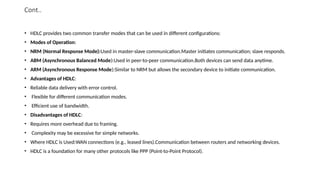
Cont..
• HDLC providestwo common transfer modes that can be used in different configurations:
• Modes of Operation:
• NRM (Normal Response Mode):Used in master-slave communication.Master initiates communication; slave responds.
• ABM (Asynchronous Balanced Mode):Used in peer-to-peer communication.Both devices can send data anytime.
• ARM (Asynchronous Response Mode):Similar to NRM but allows the secondary device to initiate communication.
• Advantages of HDLC:
• Reliable data delivery with error control.
• Flexible for different communication modes.
• Efficient use of bandwidth.
• Disadvantages of HDLC:
• Requires more overhead due to framing.
• Complexity may be excessive for simple networks.
• Where HDLC is Used:WAN connections (e.g., leased lines).Communication between routers and networking devices.
• HDLC is a foundation for many other protocols like PPP (Point-to-Point Protocol).
67.
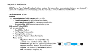
PPP (Point-to-Point Protocol)
•PPP (Point-to-Point Protocol) is a data link layer protocol that allows direct communication between two devices. It’s
commonly used to connect a home computer to the internet via an Internet Service Provider (ISP).
Services Provided by PPP:
Framing
•PPP encapsulates data inside frames, which include:
• Start/End markers (to define frame boundaries)
• Address and control fields (to manage communication)
• Error-checking field (to detect transmission errors)
Link Control Protocol (LCP)
•LCP is responsible for:
• Establishing the link
• Configuring the connection
• Testing the link for issues
• Terminating the connection when needed
Frame format
Flag: Marks the start and end(011111110)
Address: Fixed broadcast value(11111111)
Control: Manages the data type(always set to 00000011)
Protocol: Identifies the type of content(IP,IPV6)
Payload: The main data(1,500 bytes by default)
FCS: Ensures data integrity(CRC)
68.
PPP
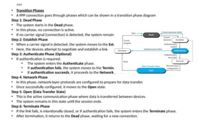
• Transition Phases
•A PPP connection goes through phases which can be shown in a transition phase diagram
Step 1: Dead Phase
• The system starts in the Dead phase.
• In this phase, no connection is active.
• If no carrier signal (connection) is detected, the system remains in this phase.
Step 2: Establish Phase
• When a carrier signal is detected, the system moves to the Establish phase.
• Here, the devices attempt to negotiate and establish a link.
Step 3: Authenticate Phase (Optional)
• If authentication is required:
• The system enters the Authenticate phase.
• If authentication fails, the system moves to the Terminate phase.
• If authentication succeeds, it proceeds to the Network phase.
Step 4: Network Phase
• In this phase, network-layer protocols are configured to prepare for data transfer.
• Once successfully configured, it moves to the Open state.
Step 5: Open (Data Transfer State)
• This is the active communication phase where data is transferred between devices.
• The system remains in this state until the session ends.
Step 6: Terminate Phase
• If the link fails, is intentionally closed, or if authentication fails, the system enters the Terminate phase.
• After termination, it returns to the Dead phase, waiting for a new connection.
69.
UNIT II NETWORKLAYER PROTOCOLS
• Network Layer – IPv4 Addressing – Network Layer Protocols (IP, ICMP and Mobile IP)- Unicast and Multicast Routing – Intradomain
and Interdomain Routing Protocols – IPv6 Addresses – IPv6 – Datagram Format - Transition from IPv4 to IPv6.