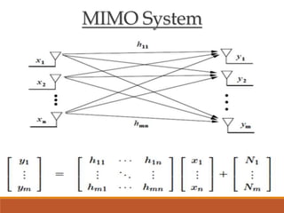
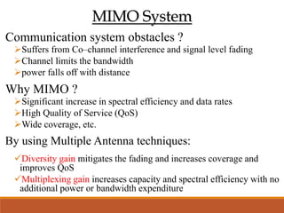
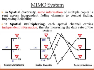
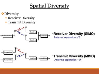
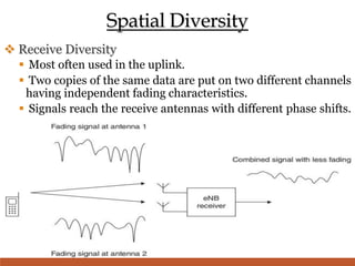
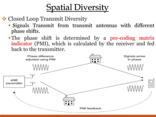
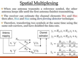
MultipleAntennatechniques
Introduced By
Murtadha Baji Eidan
Electronic and Communication Engineering
M.Sc. 2022 - 2023
Topics
 MIMO System
 Spatial Diversity
 Receive Diversity
 Transmit Diversity
 Spatial Multiplexing
 Open Loop Spatial Multiplexing
 Closed Loop Spatial Multiplexing
 Beamforming
 Multiple User MIMO
 Uplink MU-MIMO
 Downlink MU-MIMO
MIMO System
MIMO System
Communication system obstacles ?
Suffers from Co–channel interference and signal level fading
Channel limits the bandwidth
power falls off with distance
Why MIMO ?
Significant increase in spectral efficiency and data rates
High Quality of Service (QoS)
Wide coverage, etc.
By using Multiple Antenna techniques:
Diversity gain mitigates the fading and increases coverage and
improves QoS
Multiplexing gain increases capacity and spectral efficiency with no
additional power or bandwidth expenditure
MIMO System
 in Spatial diversity, same information of multiple copies is
sent across independent fading channels to combat fading,
improving Reliability
 in Spatial multiplexing, each spatial channel carries
independent information, thereby increasing the data rate of the
system
Spatial Diversity
Diversity
 Receiver Diversity
 Transmit Diversity
Spatial Diversity
 Receive Diversity
 Most often used in the uplink.
 Two copies of the same data are put on two different channels
having independent fading characteristics.
 Signals reach the receive antennas with different phase shifts.
Spatial Diversity
 Closed Loop Transmit Diversity
 Signals Transmit from transmit antennas with different
phase shifts.
The phase shift is determined by a pre-coding matrix
indicator (PMI), which is calculated by the receiver and fed
back to the transmitter.
Spatial Diversity
 Open Loop Transmit Diversity
 the transmitter uses two antennas with two successive time steps :
 Transmitter sends S1 from the First antenna and S2 from the
second Antenna.
 Transmitter sends –S2∗ from the first antenna and S1∗ from
the Second antenna .
The receiver can now make two successive measurements of the
received signal, which correspond to two different combinations
of S1 and S2.
Spatial Multiplexing
 When one antenna transmits a reference symbol, the other
antenna keeps idle until the first antenna finishes transmitting.
 The receiver can estimate the channel elements H11 and H21
then after, H12 and H22 using Zero forcing detector technique.
 Therefore, transferring two symbols at the same time using the
same sub-carriers, and have doubled the data rate.
Spatial Multiplexing
 Open Loop Spatial Multiplexing
 There is a problem with the technique described before.
 Denominator could be zero using symbol estimation
equation 𝑥1 =
𝐻22∗𝑦1 −𝐻12∗𝑦2
𝐻11∗𝐻22 −𝐻21∗𝐻12
To solve this problem:
 the receiver measures the channel elements and works out a
Rank indication (RI), which indicates the number of symbols
that it can successfully receive at a certain location.
If RI = 2 => x1 = s1 - x2 = s2 , as before
 If RI = 1 => x1 = s1 - x2 = s1 , Then the receiver equation
will be: y1 = H11*s1 + H12*s1 +n1
y2 = H21*s2 + H22*s2 +n2
Spatial Multiplexing
Open Loop Spatial Multiplexing
Spatial Multiplexing
 Closed Loop Spatial Multiplexing
 There is a problem with the technique described before.
 using the earlier equation of: y1 = H11*s1 + H12*s1 +n1,
assuming H11 = - H12 , this will leads to that the reciver will
only receive the noise power : y1 = (s1 + (-s1)) + n1
To solve this problem:
 the receiver measures the channel elements and works out a
Rank indication (RI) and a Pre-Coding Matrix Indicator (PMI)
 If RI = 1 and no PMI => x1 = s1 - x2 = s1 , as before
 If RI = 1 and has PMI => x1 = s1 - x2 = -s1 , Then the
receiver equation will be: y1 = H11*s1 + H12*(-s1) +n1
y2 = H21*s2 + H22*(-s2) +n2
Spatial Multiplexing
Closed Loop Spatial Multiplexing
Spatial Multiplexing
 Implementation Issues :
 If the antennas are too close together, then the
channel elements Hij will be very similar.
 in the case of line-of-sight transmission and
reception, the channel elements Hij are
uncorrelated with each other.
 For fast moving mobiles, delays in the feedback
loop can make the PMI unreliable by the time the
transmitter comes to use it, so open loop spatial
multiplexing is often preferred.
BeamForming
 similar to diversity transmission and reception.
 multiple antennas separation is less than diversity technique,
typically half a wavelength of the carrier frequency.
 multiple antennas increase the coverage of the cell
 main beam pointing towards mobile 1 and a null pointing
towards mobile 2
Beam Steering
 By applying a phase ramp to the transmitted signals, we can
change the direction at which constructive interference arises.
 By applying a suitable set of antenna weights. In a system
with “ N ” antennas, this allows us to adjust the direction of
the main beam and up to N - 2 nulls or sidelobes.
 It can also be used to construct a synthetic reception beam for
the uplink.
Multiuser MIMO
 uses multiple antennas to improve communication by creating
multiple connections to the same device at the same time.
helps relieve this potential congestion by creating multiple
connections to a device at the same time, which increase network
efficiency
 Takes advantage of multi-path reflecting and signal cooperating.
Multiuser MIMO
Uplink MU-MIMO
Multiuser MIMO
 Uplink MU-MIMO
 Mobiles transmit at the same time and on the same carrier frequency,
but without using any pre-coding technique.
 The base station receives their transmissions and separates them
using some techniques.
 This technique only works if the channel matrix is well behaved.
 The base station can freely choose mobiles that lead to a well-behaved
channel matrix.
 This technique does not increase the peak data rate of an individual
mobile, but it is still beneficial because of the increase in cell
throughput.
Multiuser MIMO
Downlink MU-MIMO
Multiuser MIMO
 Downlink MU-MIMO
 Base Station transmit sends two different data streams into its antenna
array instead of just one , using any pre-coding technique.
 Neither mobile has complete knowledge of the channel elements or of the
received signals.
 Transmitter has created two separate antenna beams, which share the
same sub-carriers but carry two different sets of information to be steered.
Multiuser MIMO
 Benefits of MU-MIMO
use of beamforming to direct signals toward a device.
decrease in the time each device has to wait for signals.
increase in the capacity and efficiency of a user.
Less affected by antenna correlation and channel rank
loss.
user's devices do not have to use multiple antennas.
can improve video playback streams and eliminate
some buffering or lower video quality.
Any Question ?

Multiple Antenna techniques.pptx

  • 1.
    MultipleAntennatechniques Introduced By Murtadha BajiEidan Electronic and Communication Engineering M.Sc. 2022 - 2023
  • 2.
    Topics  MIMO System Spatial Diversity  Receive Diversity  Transmit Diversity  Spatial Multiplexing  Open Loop Spatial Multiplexing  Closed Loop Spatial Multiplexing  Beamforming  Multiple User MIMO  Uplink MU-MIMO  Downlink MU-MIMO
  • 3.
  • 4.
    MIMO System Communication systemobstacles ? Suffers from Co–channel interference and signal level fading Channel limits the bandwidth power falls off with distance Why MIMO ? Significant increase in spectral efficiency and data rates High Quality of Service (QoS) Wide coverage, etc. By using Multiple Antenna techniques: Diversity gain mitigates the fading and increases coverage and improves QoS Multiplexing gain increases capacity and spectral efficiency with no additional power or bandwidth expenditure
  • 5.
    MIMO System  inSpatial diversity, same information of multiple copies is sent across independent fading channels to combat fading, improving Reliability  in Spatial multiplexing, each spatial channel carries independent information, thereby increasing the data rate of the system
  • 6.
    Spatial Diversity Diversity  ReceiverDiversity  Transmit Diversity
  • 7.
    Spatial Diversity  ReceiveDiversity  Most often used in the uplink.  Two copies of the same data are put on two different channels having independent fading characteristics.  Signals reach the receive antennas with different phase shifts.
  • 8.
    Spatial Diversity  ClosedLoop Transmit Diversity  Signals Transmit from transmit antennas with different phase shifts. The phase shift is determined by a pre-coding matrix indicator (PMI), which is calculated by the receiver and fed back to the transmitter.
  • 9.
    Spatial Diversity  OpenLoop Transmit Diversity  the transmitter uses two antennas with two successive time steps :  Transmitter sends S1 from the First antenna and S2 from the second Antenna.  Transmitter sends –S2∗ from the first antenna and S1∗ from the Second antenna . The receiver can now make two successive measurements of the received signal, which correspond to two different combinations of S1 and S2.
  • 10.
    Spatial Multiplexing  Whenone antenna transmits a reference symbol, the other antenna keeps idle until the first antenna finishes transmitting.  The receiver can estimate the channel elements H11 and H21 then after, H12 and H22 using Zero forcing detector technique.  Therefore, transferring two symbols at the same time using the same sub-carriers, and have doubled the data rate.
  • 11.
    Spatial Multiplexing  OpenLoop Spatial Multiplexing  There is a problem with the technique described before.  Denominator could be zero using symbol estimation equation 𝑥1 = 𝐻22∗𝑦1 −𝐻12∗𝑦2 𝐻11∗𝐻22 −𝐻21∗𝐻12 To solve this problem:  the receiver measures the channel elements and works out a Rank indication (RI), which indicates the number of symbols that it can successfully receive at a certain location. If RI = 2 => x1 = s1 - x2 = s2 , as before  If RI = 1 => x1 = s1 - x2 = s1 , Then the receiver equation will be: y1 = H11*s1 + H12*s1 +n1 y2 = H21*s2 + H22*s2 +n2
  • 12.
    Spatial Multiplexing Open LoopSpatial Multiplexing
  • 13.
    Spatial Multiplexing  ClosedLoop Spatial Multiplexing  There is a problem with the technique described before.  using the earlier equation of: y1 = H11*s1 + H12*s1 +n1, assuming H11 = - H12 , this will leads to that the reciver will only receive the noise power : y1 = (s1 + (-s1)) + n1 To solve this problem:  the receiver measures the channel elements and works out a Rank indication (RI) and a Pre-Coding Matrix Indicator (PMI)  If RI = 1 and no PMI => x1 = s1 - x2 = s1 , as before  If RI = 1 and has PMI => x1 = s1 - x2 = -s1 , Then the receiver equation will be: y1 = H11*s1 + H12*(-s1) +n1 y2 = H21*s2 + H22*(-s2) +n2
  • 14.
  • 15.
    Spatial Multiplexing  ImplementationIssues :  If the antennas are too close together, then the channel elements Hij will be very similar.  in the case of line-of-sight transmission and reception, the channel elements Hij are uncorrelated with each other.  For fast moving mobiles, delays in the feedback loop can make the PMI unreliable by the time the transmitter comes to use it, so open loop spatial multiplexing is often preferred.
  • 16.
    BeamForming  similar todiversity transmission and reception.  multiple antennas separation is less than diversity technique, typically half a wavelength of the carrier frequency.  multiple antennas increase the coverage of the cell  main beam pointing towards mobile 1 and a null pointing towards mobile 2
  • 17.
    Beam Steering  Byapplying a phase ramp to the transmitted signals, we can change the direction at which constructive interference arises.  By applying a suitable set of antenna weights. In a system with “ N ” antennas, this allows us to adjust the direction of the main beam and up to N - 2 nulls or sidelobes.  It can also be used to construct a synthetic reception beam for the uplink.
  • 18.
    Multiuser MIMO  usesmultiple antennas to improve communication by creating multiple connections to the same device at the same time. helps relieve this potential congestion by creating multiple connections to a device at the same time, which increase network efficiency  Takes advantage of multi-path reflecting and signal cooperating.
  • 19.
  • 20.
    Multiuser MIMO  UplinkMU-MIMO  Mobiles transmit at the same time and on the same carrier frequency, but without using any pre-coding technique.  The base station receives their transmissions and separates them using some techniques.  This technique only works if the channel matrix is well behaved.  The base station can freely choose mobiles that lead to a well-behaved channel matrix.  This technique does not increase the peak data rate of an individual mobile, but it is still beneficial because of the increase in cell throughput.
  • 21.
  • 22.
    Multiuser MIMO  DownlinkMU-MIMO  Base Station transmit sends two different data streams into its antenna array instead of just one , using any pre-coding technique.  Neither mobile has complete knowledge of the channel elements or of the received signals.  Transmitter has created two separate antenna beams, which share the same sub-carriers but carry two different sets of information to be steered.
  • 23.
    Multiuser MIMO  Benefitsof MU-MIMO use of beamforming to direct signals toward a device. decrease in the time each device has to wait for signals. increase in the capacity and efficiency of a user. Less affected by antenna correlation and channel rank loss. user's devices do not have to use multiple antennas. can improve video playback streams and eliminate some buffering or lower video quality.
  • 24.