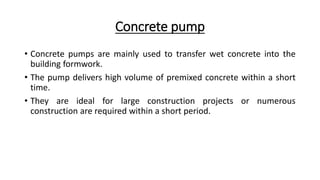
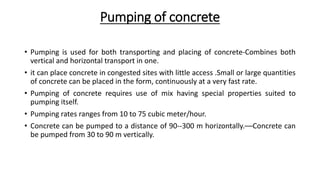
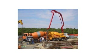
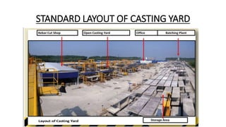
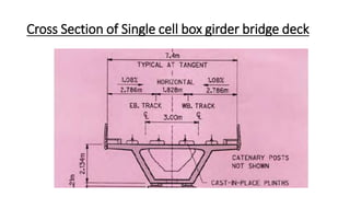
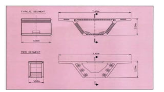
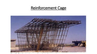
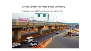
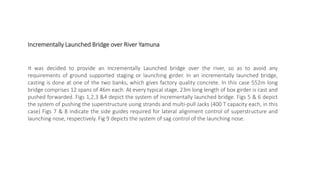
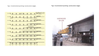
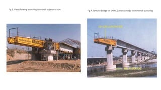
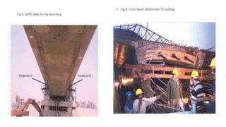
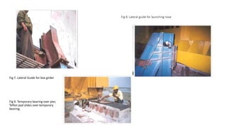
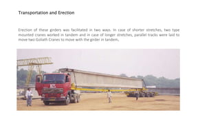
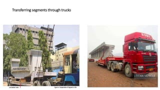
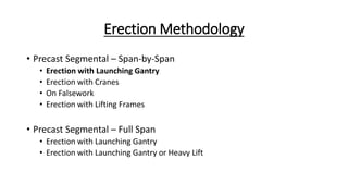
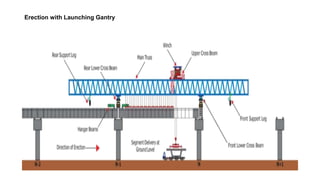
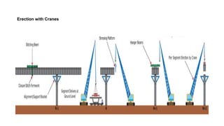
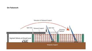
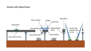
Technology for Infrastructure Construction
Guided by,
Dr. Debasis Sarkar
Associate Professor
PDEU
Submitted by,
ABHISHEK PARMAR (20MCL001)
AXAY SHARMA (20MCL002)
CASE STUDY OF SEGMENT CASTING AND TRANSPORTATION
FOR ELEVATED CORRIDOR METRO RAIL PROJECT
1
Concrete pump
• Concrete pumps are mainly used to transfer wet concrete into the
building formwork.
• The pump delivers high volume of premixed concrete within a short
time.
• They are ideal for large construction projects or numerous
construction are required within a short period.
Pumping of concrete
• Pumping is used for both transporting and placing of concrete-Combines both
vertical and horizontal transport in one.
• it can place concrete in congested sites with little access .Small or large quantities
of concrete can be placed in the form, continuously at a very fast rate.
• Pumping of concrete requires use of mix having special properties suited to
pumping itself.
• Pumping rates ranges from 10 to 75 cubic meter/hour.
• Concrete can be pumped to a distance of 90--300 m horizontally.––Concrete can
be pumped from 30 to 90 m vertically.
Types of pumps
• Main pumps:
• Boom pump
• Line pump
• Pneumatic pump
• Squeeze pump
• There are two main configurations of concrete pumping equipment:
(1) pump with a separate pipeline
(2) a pump and boom combination
• third, less common configuration, used mostly in high-rise construction, the
pump and pipeline with a separate, tower-mounted boom.
Different type of pump
Stationary pump.
• The pump is mounted on a steel frame and stationed in a fixed location
throughout construction. This configuration is suitable for limited-area sites
with large and frequent concreting operations.
Trailer pump.
• The pump is mounted on a one- or two-axle trailer to enable easy on-site
relocation as well as movement between sites.
• It is suitable mainly for spread-out sites. One pump can also serve several
adjacent sites, as it can be moved between them according to concreting
schedule.
Truck pump
• Truck-mounted pump and boom combination, this quick setup pump is
moved between sites and operated on a standard truck chassis.
• It is commonly used for one-time concrete operations (such as in small-scale
repair or renovation projects, or on a regular construction project prior to
setup of the main concrete transportation equipment) when a reach greater
than that provided by a pump-truck boom is needed.
Advantages of concrete pumping
• Faster concrete placement
• Less labour
• Improved concrete
• Concrete pouring accuracy
• convenience
SEGMENT CASTING
METHODS OF SEGMENT CASTING
1. LONG LINE METHOD
2. SHORT LINE METHOD
1. LONG LINE METHOD
• All segments of a span are manufactured on a fixed bed with the formwork
moving along the bed for successive casting operation.
• All segments are cast on a soffit which is a full span upto coupling section
in a span by span method.
 Advantage
• The obvious advantage is that all the geometry control is done when
constructing the soffit thus simplifying this process during segment
production and avoiding errors in geometry control in finished structure.
Disadvantage
• It requires a large area.
• The soffit can not be used for new project.
• The soffit can be made for only one casting curve.
2. SHORT LINE METHOD
• It is a match casting process.
• Stationary forms are used next to the previously cast segment in order to get a
homogeneous perfect fitting match-cast joint.
Advantage
• Space requirements are much less compared to the long line method.
• The entire manufacturing process is centralized.
• The system is extremely adaptable to geometry variations such as horizontal and
vertical curvature and super elevation transition which are obtained without
increase in costs.
• The forms are reusable for other projects.
STANDARD LAYOUT OF CASTING YARD
Cross Section of Single cell box girder bridge deck
Reinforcement Cage
Casting Form
Batching and mixing of concrete
• Raw material Cement (OPC grade 53)
• Fly Ash (Maximum 30% of cement)
• Water (between 0.1 & 0.4)
• Admixture (SP-430, SP-432)
• Fine aggregate Coarse aggregates of 10mm & 20mm size
Batching procedure
• Batching plant may be of manually operated type or may be operated with the
help of computer aided software.
• The quantities are filled in the computer and start key is pressed, the sensors
provided near the gates get into action and according to the load scale value, that
much quantity of sand, 10mm aggregates, & 20mm aggregates are filled in a
bucket.
• When the required quantity of the aggregates is filled the gates get closed
automatically and the bucket is pulled up.
• As the bucket reaches the top,
its contents are put into a mixing
pan, where it gets mixed with
the cement, water & admixtures
from their separate hoppers.
Mixing tank
QUALITY CONTROL
• Initial Set Up Survey - Required for formwork setting and getting the match cast
segment in “rough” position.
• Final Set Up Survey - Required for final adjustments of the match cast segment
and small adjustments to the formwork once the forms have been closed up to
final position.
• As Cast Survey - Required to obtain “as cast” data on the segment used to
determine the positioning of the segment in the “match cast” position.
• Inputting Data - Required for geometry control for the for the next segment to
be cast.
Ranjit Buildcon Casting Yard
• India has taken a giant leap in the field of construction over the past 15-20 years. And infrastructure
development is feather to the cap. A large number of cities are constructing metro projects. Similarly, an
average of about 35 km of road is constructed every day in the country, which perhaps is the most rapid
expansion in the world. In most urban habitats, it becomes inevitable to go for long elevated viaducts, as
effective means of transport. These elevated viaducts easily clear the congested roads and other
inhabitations, at ground level leaving them unhindered. However, certain difficulties may be faced in locating
the substructures and foundations caused due to underground/ elevated utilities, land encroachments,
important establishments etc. Once the difficulties are surmounted, the elevated viaducts tend to provide
seamless connectivity. Needless to mention that they create additional movement area, without jeopardizing
the existing ground level network.
• Several such elevated viaducts have been constructed in the country, and some are in different phases of
construction. To name a few, 3 phases of Delhi Metro, over 60 km of Bangalore Metro, 30 km long Noida-
Greater Noida Metro, Bangalore Hosur Elevated Expressway, Delhi Gurgaon Expressway, Barapulla Nallah
Elevated Road, Badarpur Elevated Corridor etc.
• It is understood and agreed by masses that Metro Rail is the best means of transporting large set of
commuters, especially in mega cities. Like any developing/developed country, Delhi also started planning of
Metro project in the year 1995. About 60 km was constructed in Phase-1, 130 km in Phase-2 and another 110
km is now nearing completion in Phase-3. Essential ingredients of structures of a Metro Rail are i) Viaduct, ii)
Elevated Station, iii) Tunnel, iv) Underground Station, v) Workshop-cum-Depot etc. Similary, other major cities
where metro is under construction are Bangalore, Chennai, Kochi, Kolkata, Lucknow, Meerut, Agra, Bhopal,
Indore, Nagpur, Pune, Mumbai, Jaipur etc.
• a large number of long elevated viaducts are in various phases of construction. These include 26 km long
Delhi-Gurgaon Toll Raod, 10 km long Bangalore-Hosur Elevated Toll Expressway, 4 km long Barapullah Elevated
Viaduct, 4 km long Badarpur Elevated Expressway etc. All these viaducts are servicing their intended purpose
efficiently. In fact, it is difficult to imagine life without these metro & road viaducts.
Elevated Corridors For - Metro & Road Connectivity
Vinay Gupta, Director & CEO, Tandon Consultants Pvt. Ltd. New Delhi
It was decided to provide an Incrementally Launched bridge over the river, so as to avoid any
requirements of ground supported staging or launching girder. In an incrementally launched bridge,
casting is done at one of the two banks, which gives factory quality concrete. In this case 552m long
bridge comprises 12 spans of 46m each. At every typical stage, 23m long length of box girder is cast and
pushed forwarded. Figs 1,2,3 &4 depict the system of incrementally launched bridge. Figs 5 & 6 depict
the system of pushing the superstructure using strands and multi-pull Jacks (400 T capacity each, in this
case) Figs 7 & 8 indicate the side guides required for lateral alignment control of superstructure and
launching nose, respectively. Fig 9 depicts the system of sag control of the launching nose.
Incrementally Launched Bridge over River Yamuna
Fig 1. Incremental launching: Construction stages Fig 2. Incremental launching: construction stages
Fig 3. View showing launching nose with superstructure Fig 4. Yamuna bridge for DMRC Construcetd by incremental launching
Fig 5. Soffit view during launching
• Fig 6. Cross beam attachment for pulling
Fig 8. Lateral guide for launching nose
Fig 7. Lateral Guide for box girder
Fig 9. Temporary bearing over pier,
Teflon pad slides over temporary
bearing.
Transportation and Erection
Erection of these girders was facilitated in two ways. In case of shorter stretches, two type
mounted cranes worked in tandem and in case of longer stretches, parallel tracks were laid to
move two Goliath Cranes to move with the girder in tandem.
Transferring segments through trucks
Erection Methodology
• Precast Segmental – Span-by-Span
• Erection with Launching Gantry
• Erection with Cranes
• On Falsework
• Erection with Lifting Frames
• Precast Segmental – Full Span
• Erection with Launching Gantry
• Erection with Launching Gantry or Heavy Lift
Erection with Launching Gantry
Erection with Cranes
On Falsework
Erection with Lifting Frames
References
• https://www.zaubacorp.com/company/RANJIT-BUILDCON-
LIMITED/U45206GJ2006PLC049570
• https://www.nbmcw.com/articles-reports/building-construction-
material/precast-construction/elevated-corridors-for-metro-road-
connectivity.html
• https://www.tcpl.com/
• https://www.youtube.com/watch?v=7rIDv7Q_Cy4
THANK YOU

Metro rail segments

  • 1.
    Technology for InfrastructureConstruction Guided by, Dr. Debasis Sarkar Associate Professor PDEU Submitted by, ABHISHEK PARMAR (20MCL001) AXAY SHARMA (20MCL002) CASE STUDY OF SEGMENT CASTING AND TRANSPORTATION FOR ELEVATED CORRIDOR METRO RAIL PROJECT 1
  • 2.
    Concrete pump • Concretepumps are mainly used to transfer wet concrete into the building formwork. • The pump delivers high volume of premixed concrete within a short time. • They are ideal for large construction projects or numerous construction are required within a short period.
  • 3.
    Pumping of concrete •Pumping is used for both transporting and placing of concrete-Combines both vertical and horizontal transport in one. • it can place concrete in congested sites with little access .Small or large quantities of concrete can be placed in the form, continuously at a very fast rate. • Pumping of concrete requires use of mix having special properties suited to pumping itself. • Pumping rates ranges from 10 to 75 cubic meter/hour. • Concrete can be pumped to a distance of 90--300 m horizontally.––Concrete can be pumped from 30 to 90 m vertically.
  • 4.
    Types of pumps •Main pumps: • Boom pump • Line pump • Pneumatic pump • Squeeze pump
  • 5.
    • There aretwo main configurations of concrete pumping equipment: (1) pump with a separate pipeline (2) a pump and boom combination • third, less common configuration, used mostly in high-rise construction, the pump and pipeline with a separate, tower-mounted boom.
  • 6.
    Different type ofpump Stationary pump. • The pump is mounted on a steel frame and stationed in a fixed location throughout construction. This configuration is suitable for limited-area sites with large and frequent concreting operations. Trailer pump. • The pump is mounted on a one- or two-axle trailer to enable easy on-site relocation as well as movement between sites. • It is suitable mainly for spread-out sites. One pump can also serve several adjacent sites, as it can be moved between them according to concreting schedule.
  • 7.
    Truck pump • Truck-mountedpump and boom combination, this quick setup pump is moved between sites and operated on a standard truck chassis. • It is commonly used for one-time concrete operations (such as in small-scale repair or renovation projects, or on a regular construction project prior to setup of the main concrete transportation equipment) when a reach greater than that provided by a pump-truck boom is needed.
  • 10.
    Advantages of concretepumping • Faster concrete placement • Less labour • Improved concrete • Concrete pouring accuracy • convenience
  • 11.
  • 12.
    METHODS OF SEGMENTCASTING 1. LONG LINE METHOD 2. SHORT LINE METHOD
  • 13.
    1. LONG LINEMETHOD • All segments of a span are manufactured on a fixed bed with the formwork moving along the bed for successive casting operation. • All segments are cast on a soffit which is a full span upto coupling section in a span by span method.  Advantage • The obvious advantage is that all the geometry control is done when constructing the soffit thus simplifying this process during segment production and avoiding errors in geometry control in finished structure.
  • 14.
    Disadvantage • It requiresa large area. • The soffit can not be used for new project. • The soffit can be made for only one casting curve.
  • 15.
    2. SHORT LINEMETHOD • It is a match casting process. • Stationary forms are used next to the previously cast segment in order to get a homogeneous perfect fitting match-cast joint.
  • 17.
    Advantage • Space requirementsare much less compared to the long line method. • The entire manufacturing process is centralized. • The system is extremely adaptable to geometry variations such as horizontal and vertical curvature and super elevation transition which are obtained without increase in costs. • The forms are reusable for other projects.
  • 18.
    STANDARD LAYOUT OFCASTING YARD
  • 19.
    Cross Section ofSingle cell box girder bridge deck
  • 21.
  • 22.
  • 23.
    Batching and mixingof concrete • Raw material Cement (OPC grade 53) • Fly Ash (Maximum 30% of cement) • Water (between 0.1 & 0.4) • Admixture (SP-430, SP-432) • Fine aggregate Coarse aggregates of 10mm & 20mm size
  • 24.
    Batching procedure • Batchingplant may be of manually operated type or may be operated with the help of computer aided software. • The quantities are filled in the computer and start key is pressed, the sensors provided near the gates get into action and according to the load scale value, that much quantity of sand, 10mm aggregates, & 20mm aggregates are filled in a bucket. • When the required quantity of the aggregates is filled the gates get closed automatically and the bucket is pulled up.
  • 26.
    • As thebucket reaches the top, its contents are put into a mixing pan, where it gets mixed with the cement, water & admixtures from their separate hoppers. Mixing tank
  • 27.
    QUALITY CONTROL • InitialSet Up Survey - Required for formwork setting and getting the match cast segment in “rough” position. • Final Set Up Survey - Required for final adjustments of the match cast segment and small adjustments to the formwork once the forms have been closed up to final position. • As Cast Survey - Required to obtain “as cast” data on the segment used to determine the positioning of the segment in the “match cast” position. • Inputting Data - Required for geometry control for the for the next segment to be cast.
  • 28.
  • 31.
    • India hastaken a giant leap in the field of construction over the past 15-20 years. And infrastructure development is feather to the cap. A large number of cities are constructing metro projects. Similarly, an average of about 35 km of road is constructed every day in the country, which perhaps is the most rapid expansion in the world. In most urban habitats, it becomes inevitable to go for long elevated viaducts, as effective means of transport. These elevated viaducts easily clear the congested roads and other inhabitations, at ground level leaving them unhindered. However, certain difficulties may be faced in locating the substructures and foundations caused due to underground/ elevated utilities, land encroachments, important establishments etc. Once the difficulties are surmounted, the elevated viaducts tend to provide seamless connectivity. Needless to mention that they create additional movement area, without jeopardizing the existing ground level network. • Several such elevated viaducts have been constructed in the country, and some are in different phases of construction. To name a few, 3 phases of Delhi Metro, over 60 km of Bangalore Metro, 30 km long Noida- Greater Noida Metro, Bangalore Hosur Elevated Expressway, Delhi Gurgaon Expressway, Barapulla Nallah Elevated Road, Badarpur Elevated Corridor etc.
  • 32.
    • It isunderstood and agreed by masses that Metro Rail is the best means of transporting large set of commuters, especially in mega cities. Like any developing/developed country, Delhi also started planning of Metro project in the year 1995. About 60 km was constructed in Phase-1, 130 km in Phase-2 and another 110 km is now nearing completion in Phase-3. Essential ingredients of structures of a Metro Rail are i) Viaduct, ii) Elevated Station, iii) Tunnel, iv) Underground Station, v) Workshop-cum-Depot etc. Similary, other major cities where metro is under construction are Bangalore, Chennai, Kochi, Kolkata, Lucknow, Meerut, Agra, Bhopal, Indore, Nagpur, Pune, Mumbai, Jaipur etc. • a large number of long elevated viaducts are in various phases of construction. These include 26 km long Delhi-Gurgaon Toll Raod, 10 km long Bangalore-Hosur Elevated Toll Expressway, 4 km long Barapullah Elevated Viaduct, 4 km long Badarpur Elevated Expressway etc. All these viaducts are servicing their intended purpose efficiently. In fact, it is difficult to imagine life without these metro & road viaducts.
  • 33.
    Elevated Corridors For- Metro & Road Connectivity Vinay Gupta, Director & CEO, Tandon Consultants Pvt. Ltd. New Delhi
  • 34.
    It was decidedto provide an Incrementally Launched bridge over the river, so as to avoid any requirements of ground supported staging or launching girder. In an incrementally launched bridge, casting is done at one of the two banks, which gives factory quality concrete. In this case 552m long bridge comprises 12 spans of 46m each. At every typical stage, 23m long length of box girder is cast and pushed forwarded. Figs 1,2,3 &4 depict the system of incrementally launched bridge. Figs 5 & 6 depict the system of pushing the superstructure using strands and multi-pull Jacks (400 T capacity each, in this case) Figs 7 & 8 indicate the side guides required for lateral alignment control of superstructure and launching nose, respectively. Fig 9 depicts the system of sag control of the launching nose. Incrementally Launched Bridge over River Yamuna
  • 35.
    Fig 1. Incrementallaunching: Construction stages Fig 2. Incremental launching: construction stages
  • 36.
    Fig 3. Viewshowing launching nose with superstructure Fig 4. Yamuna bridge for DMRC Construcetd by incremental launching
  • 37.
    Fig 5. Soffitview during launching • Fig 6. Cross beam attachment for pulling
  • 38.
    Fig 8. Lateralguide for launching nose Fig 7. Lateral Guide for box girder Fig 9. Temporary bearing over pier, Teflon pad slides over temporary bearing.
  • 39.
    Transportation and Erection Erectionof these girders was facilitated in two ways. In case of shorter stretches, two type mounted cranes worked in tandem and in case of longer stretches, parallel tracks were laid to move two Goliath Cranes to move with the girder in tandem.
  • 40.
  • 41.
    Erection Methodology • PrecastSegmental – Span-by-Span • Erection with Launching Gantry • Erection with Cranes • On Falsework • Erection with Lifting Frames • Precast Segmental – Full Span • Erection with Launching Gantry • Erection with Launching Gantry or Heavy Lift
  • 42.
  • 43.
  • 44.
  • 45.
  • 47.
  • 48.