
Recommended
More Related Content
More from olfjsekdmmes
More from olfjsekdmmes (20)
Recently uploaded
Recently uploaded (18)
Mercruiser sterndrive mc 200 mr service repair manual sn6849290 to 0a471374
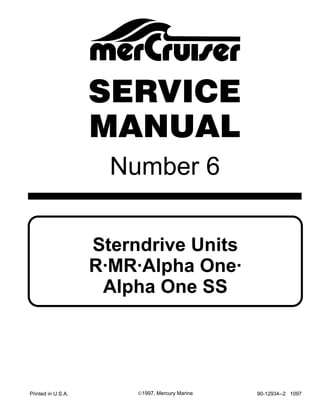
- 1. Number 6 Printed in U.S.A. 90-12934--2 1097©1997, Mercury Marine Sterndrive Units R·MR·Alpha One· Alpha One SS SERVICE MANUAL
- 3. 90-12934--2 1097 i Models Covered in This Manual Transom Assemblies Model Serial Number MC 120R/140B/185R/488R/898R/228R/260R 6216687 – 6849289 MC 120MR/140MR/170MR/185MR/190MR/200MR/ 230MR/260MR/300 Tempest MR 6849290 – 0A471374 MC Alpha One/Alpha One SS 0A471375 and Above Sterndrive Units MC 120R-260R Original Ratio Ratio If Serviced With 13:21 Gears Serial Number 1.98:1 1.94:1 6237861-6854392 1.84:1 1.81:1 6225577-6862701 1.65:1 1.62:1 6268065-6810537 1.50:1 1.47:1 6229158-6847029 1.32:1 1.29:1 6231571-6663947 MC 120 MR - 300 TEMPEST MR Original Ratio Ratio If Serviced With 13:28 Gears Serial Number 1.98:1 1.94:1 6854393-0A476746 1.84:1 1.81:1 6862702-0A470164 1.65:1 1.62:1 6810538-0A475786 1.50:1 1.47:1 6847030-0A479506 MC ALPHA ONE / ALPHA ONE SS Original Ratio Ratio If Serviced With 13:28 Gears R.H. Serial Number L.H. Serial Number 1.98:1 1.98:1 0A476747 and Above 0C881740 and Above 1.84:1 1.84:1 0A470165 and Above 0C884040 and Above 1.65:1 1.65:1 0A475787 and Above 0C881790 and Above 1.50:1 1.50:1 0A479507 and Above 0C852908 and Above 1.32:1 1.32:1 0A613927 and Above Alpha One SS 1.50:1/1.32:1 1.50/1.32:1 0A545004 and Above
- 4. 90-12934--2 1097ii Sea Ray Sterndrive Units and Transom Assembly (Oyster White) Original Ratio Ratio If Serviced With 13:21 Gears Serial Number 1.98:1 0B803866-0C348031 1.84:1 0B800854-0C343526 1.50:1 0B796473-0C340666 1.32:1 0B804807-0C340030 Transom Assembly 0B815811-0C340333 When making repairs to Sea Ray (Oyster White) sterndrives, follow procedures as outlined for corresponding MerCruiser models as shown in the cross-reference chart below. Sea Ray MerCruiser 3.0L 3.0L Alpha One 4.3L2 4.3L Alpha One 4.3L4 4.3LX Alpha One 5.7L 5.7L Alpha One SRX 5.7L 350 Magnum Alpha One SRX 7.4L 454 Magnum Alpha One
- 5. 90-12934--2 1097 iii Notice Throughout this publication, “Warnings” and “Cau- tions” (accompanied by the International HAZARD symbol ! ) are used to alert the mechanic to special instructions concerning a particular service or opera- tion that may be hazardous if performed incorrectly or carelessly. — OBSERVE THEM CAREFULLY! These “Safety Alerts” alone cannot eliminate the hazards that they signal. Strict compliance to these special instructions when performing the service, plus “common sense” operation, are major accident prevention measures. DANGER! DANGER - Immediate hazards which will result in severe personal injury or death. ! WARNING WARNING - Hazards or unsafe practices which COULD result in severe personal injury or death. ! CAUTION CAUTION - Hazards or unsafe practices which could result in minor personal injury or product or property damage. IMPORTANT: Indicates information or instruc- tions that are necessary for proper operation and/or maintenance. Notice To Users of This Manual This service manual has been written and published by the service department of the manufacturer to aid our dealers’ mechanics and company service per- sonnel when servicing the product described herein. It is assumed that these personnel are familiar with the servicing procedures of this product, or like or similar products. That they have been trained in the recommended servicing procedures of these prod- ucts which includes the use of mechanics’ common hand tools from other suppliers. We could not possibly know of and advise the service trade of all conceivable procedures by which a service might be performed and of all possible hazards and/or result of each method. We have not undertaken any such wise evaluation. Therefore, anyone who uses a service procedure and/or tool which is not recommended by the manufacturer, first must completely satisfy himself that neither his nor the product’s safety will be endangered by the service procedure selected. All information, illustrations, and specifications con- tained in this manual are based on the latest product information available at time of publication. As required, revisions to this manual will be sent to all dealers contracted by us to sell and/or service these products.
- 6. 90-12934--2 1097iv Replacement Parts ! WARNING Electrical system components on gasoline engines and MerCruiser Stern Drives are designed and manufactured to comply with U.S. Coast Guard Rules and Regulations to minimize risks of fire or explosion. Use of replacement electrical system compo- nents, which do not comply to these rules and regulations, could result in a fire or explosion hazard and should be avoided. When servicing electrical systems, it is extremely important that all components are properly installed and tightened. If not, any electrical component opening would permit sparks to ignite fuel vapors from fuel system leaks, if they exist or develop. ! WARNING Electrical system components on diesel engines are not external ignition protected. DO NOT STORE OR UTILIZE GASOLINE ON BOATS EQUIPPED WITH THESE ENGINES, UNLESS PROVISIONS HAVE BEEN MADE TO EXCLUDE GASOLINE VAPORS FROM ENGINE COMPART- MENT (ref: 33 CFR). Failure to comply could result in fire, explosion and/or severe personal injury.
- 7. Important Information Removal, Installation and Adjustments Sterndrive Unit Transom Assembly Power Trim Steering Systems Corrosion Protection 1 2 3 4 5 6 7 90-12934--2 1097 v Service Manual Outline Section 1 - Important Information A - Important Information B - Maintenance C - Troubleshooting Section 2 - Removal, Installation and Adjustments A - All Models Section 3 - Sterndrive Unit A - Drive Shaft Housing B - Gear Housing - MR/Alpha One/Alpha One SS C - Gear Housing - I-R D - Gear Housing - Alpha One Counter Rotation Section 4 - Transom Assembly A - Service Procedures Requiring Minor Disassembly B - Service Procedures Requiring Major Disassembly Section 5 - Power Trim A - Oildyne Power Trim Pump (Plastic Reservoir) B - Oildyne Power Trim Pump (Aluminum Reservoir) C - Prestolite Power Trim Pump D - Trim Cylinders E - Dual Power Trim Control F - Auto Trim II Section 6 - Steering Systems A - Power Steering B - Manual Steering Section 7 - Corrosion Protection A - All Models
- 9. 1A-0 - IMPORTANT INFORMATION 90-12934--2 1097 Table of Contents Page How To Use This Manual 1A-1. . . . . . . . . . . . . . . . . . Page Numbering 1A-1. . . . . . . . . . . . . . . . . . . . . . Introduction 1A-1. . . . . . . . . . . . . . . . . . . . . . . . . . . . . . Special Product Information 1A-1. . . . . . . . . . . . . . . Directional References 1A-1. . . . . . . . . . . . . . . . . . . . Propeller Rotation 1A-1. . . . . . . . . . . . . . . . . . . . . . . . Serial Number Locations 1A-2. . . . . . . . . . . . . . . . . . Hi-Performance Boating 1A-2. . . . . . . . . . . . . . . . . . . Sterndrive Unit 10-Hour Break-In Period 1A-2. . . . Decal Application 1A-2. . . . . . . . . . . . . . . . . . . . . . . . . Decal Removal 1A-2. . . . . . . . . . . . . . . . . . . . . . . . Temperature 1A-2. . . . . . . . . . . . . . . . . . . . . . . . Surface Preparation 1A-2. . . . . . . . . . . . . . . . . Decal Application 1A-2. . . . . . . . . . . . . . . . . . . . . . Painting Procedures 1A-3. . . . . . . . . . . . . . . . . . . . . . Cleaning & Painting Aluminum Propellers & Gear Housings 1A-3. . . . . . . . . . . . . . . . . . . . . . Propellers 1A-3. . . . . . . . . . . . . . . . . . . . . . . . . . Gear Housings 1A-3. . . . . . . . . . . . . . . . . . . . .
- 10. IMPORTANT INFORMATION - 1A-190-12934--2 1097 How To Use This Manual This Manual is divided into sections which represent major components and systems. Some sections are further divided into parts which more fully describe the component. Sections and parts are listed on page. Page Numbering Two number groups appear at the bottom of each page. Following is an example and description. Introduction This comprehensive overhaul and repair manual is designed as a service guide for the MerCruiser models previously listed. It provides specific information, including procedures for disassembly, inspection, assembly and adjustment, to enable dealers and service mechanics to repair these products. Before attempting repairs, it is suggested that proce- dure first be read through to gain knowledge of the methods and tools used and the cautions and warnings required for safety. Special Product Information During production of these models, special product improvements and changes have been made to increase product reliability and performance. Such changes to a sterndrive assembly component(s) are covered in the “Special Information” portion of the appropriate sterndrive assembly section. (Refer to the section “Index”.) Serial number breaks are provided, where applicable, for ease of identification. Directional References Front of boat is bow; rear is stern. Starboard side is right side; port side is left side. In this service manual, all directional references are given as they appear when viewing boat from stern, looking toward bow. Propeller Rotation Propeller rotation for sterndrive can be right hand or left hand rotation as viewed from the aft end of the propeller. 22266 22267 Right Hand Rotation Left Hand Rotation
- 11. 1A-2 - IMPORTANT INFORMATION 90-12934--2 1097 Serial Number Locations 23254 Transom Assembly Serial Number Location a - Transom Assembly Serial Number 23254 Sterndrive Unit Serial Number Location – Port Decal a - Sterndrive Unit Serial Number b - Sterndrive Unit Gear Ratio Hi-Performance Boating Written by marine engineers, order Part No. 90-86168, entitled “Hi-Performance Boat Opera- tion.” Sterndrive Unit 10-Hour Break-In Period (New or with Replacement Gears) 1. Avoid full throttle starts. 2. DO NOT operate at any one constant speed for extended periods of time. 3. DO NOT exceed 75% of full throttle during the first 5 hours. During the next 5 hours, operate at intermittent full throttle. 4. Drive unit should be shifted into forward gear a minimum of 10 times during break-in, with run-in time at moderate RPM after each shift. Decal Application Decal Removal 1. Mark decal location before removal to assure proper alignment of new decal. 2. Carefully soften decal and decal adhesive with a heat gun or heat blower while removing old decal. 3. Clean decal contact area with a 1:1 mixture of iso- propyl alcohol and water. 4. Thoroughly dry decal contact area and check for a completely cleaned surface. TEMPERATURE IMPORTANT: Installation of vinyl decals should not be attempted while in direct sunlight. Air and surface temperature should be between 60°F (15°C) and 100°F (38°C) for best application. SURFACE PREPARATION IMPORTANT: Do not use a soap or any petroleum based solvents to clean application surface. Decal Application NOTE: Ensure area where decal will be applied is clean. 1. Remove backing from decal. 2. Apply to drive unit. 3. Carefully smooth decal on surface.
- 12. IMPORTANT INFORMATION - 1A-390-12934--2 1097 Painting Procedures Cleaning & Painting Aluminum Propellers & Gear Housings ! WARNING Avoid serious injury from flying debris. Avoid se- rious injury from airborne particles. Use eye and breathing protection with proper ventilation. PROPELLERS 1. Sand the entire area to be painted with 3M 120 Regalite Polycut or coarse Scotch-Brite, disc or belts. 2. Feather edges of all broken paint edges. Try not to sand through the primer. 3. Clean the surface to be painted using PPG Industries DX330 Wax and Grease Remover or equivalent (Xylene or M.E.K.). 4. If bare metal has been exposed, use Quicksil- ver’s Light Gray Primer. 5. Allow a minimum of 1 hour dry time and no more than 1 week before applying the finish coat. 6. Apply the finish coat using Quicksilver’s EDP Propeller Black. GEAR HOUSINGS The following procedures should be used in refinish- ing gear housings. This procedure will provide the most durable paint system available in the field. The materials recommended are of high quality and approximate marine requirements. The following procedure will provide a repaint job that compares with a properly applied factory paint finish. It is rec- ommended that the listed materials be purchased from a local Ditzler Automotive Finish Supply Outlet. The minimum package quantity of each material shown following is sufficient to refinish several gear housings. Procedure: 1. Wash gear housing with a muriatic acid base cleaner to remove any type of marine growth and rinse with water, if necessary. 2. Wash gear housing with soap and water, then rinse. 3. Sand blistered area with 3M 180 grit sandpaper or P180 Gold Film Disc to remove paint blisters only. Feather edge all broken paint edges. 4. Clean gear housing thoroughly with (DX-330) wax and grease remover. 5. Spot repair surfaces where bare metal is ex- posed with (DX-503) alodine treatment. IMPORTANT: Do not use any type of aerosol spray paints as the paint will not properly adhere to the surface nor will the coating be sufficiently thick to resist future paint blistering. 6. Mix epoxy chromate primer (DP-40) with equal part catalyst (DP-401) per manufacturer’s instructions, allowing proper induction period for permeation of the epoxy primer and catalyst. 7. Allow a minimum of one hour drying time and no more than one week before top coating assem- blies. 8. Use Ditzler Urethane DU9000 for Mercury Black and DU33414M for Sea Ray White. Catalyze all three colors with Ditzler DU5 catalyst mixed 1:1 ratio. Reduce with solvents per Ditzler label. ! CAUTION Be sure to comply with instructions on the label for ventilation and respirators. Using a spray gun, apply one half to one mil even film thick- ness. Let dry, flash off for five minutes and apply another even coat of one half to one mil film thick- ness. This urethane paint will dry to the touch in a matter of hours, but will remain sensitive to scratches and abrasions for a few days. 9. The type of spray gun used will determine the proper reduction ratio of the paint. IMPORTANT: Do not paint sacrificial trim tab or anode. 10. Cut out a cardboard “plug” for trim tab pocket to keep paint off of mating surface to maintain good continuity circuitry between trim tab and gear housing.
- 14. 2A-0 –REMOVAL, INSTALLATION AND ADJUSTMENTS 90-12934--2 1097 Table of Contents Page Specifications 2A-1. . . . . . . . . . . . . . . . . . . . . . . . . . Torque Specifications 2A-1. . . . . . . . . . . . . . . . . . Lubricants/Sealers/Adhesives 2A-1. . . . . . . . . . . . Special Installation Tools 2A-1. . . . . . . . . . . . . . . . Special Information 2A-1. . . . . . . . . . . . . . . . . . . . . Transom Specifications 2A-1. . . . . . . . . . . . . . . . Checking Transom Thickness 2A-2. . . . . . . . . . . . Sterndrive Unit Removal 2A-2. . . . . . . . . . . . . . . . Transom Assembly Removal 2A-3. . . . . . . . . . . . Transom Assembly Installation 2A-7. . . . . . . . . . . Sterndrive Unit Installation 2A-15. . . . . . . . . . . . . . Shift Cable Adjustment 2A-18. . . . . . . . . . . . . . . . . Installing Shift Cables 2A-19. . . . . . . . . . . . . . . . Propeller Installation 2A-24. . . . . . . . . . . . . . . . . . .
- 15. 90-12934--2 1097 REMOVAL, INSTALLATION AND ADJUSTMENT 2A-1 Specifications Torque Specifications NOTE: Listed below are the torque specifications for those fasteners which have a specific torque value. Tighten all other fasteners (not listed) securely. DESCRIPTION TORQUE DESCRIPTION lb. in. lb. ft. N⋅m Exhaust Pipe To Gimbal Housing Screws 20-25 27-34 Power Trim Cylinder To An- chor Pin Nut Tighten Until Nut Just Bottoms Out Propeller 55 (Min.) 75 (Min.) Shift Cable End Guide At- taching Nuts Tighten Until Nut Bot- toms And Then Loosen 1/2 Turn Steering Cable Coupler Nut 35 48 Steering Cable Coupler Nut Locking Plate Screw 60-72 7-8 Steering System Pivot Bolts 25 34 Sterndrive Unit To Bell Housing Attaching Nuts 50 68 Transom Assembly Attach- ing Screws and Nuts 20-25 27-34 Power Steering Hydraulic Hose Fitting - Large 20-25 27-34 Power Steering Hydraulic Hose Fitting - Small 96-108 11-12 Lubricants/Sealers/ Adhesives Description Part No. Quicksilver 2-4-C Marine Lubricant With Teflon 92-825407A3 Quicksilver Special Lubricant 101 92-13872A1 Liquid Neoprene 92-25711-2 Perfect Seal 92-34227--1 Engine Coupler Spline Grease 92-816391A4 Special Installation Tools Description Part No. Alignment Tool Assembly 91-805475A1 Engine Alignment Tool 91-57797A3 Special Information Transom Specifications 22170 a - Transom Thickness-to Be 2 In. (51 mm) Minimum To 2-1/4 in. (57 mm) Maximum b - Transom Surfaces-MUST BE Parallel Within 1/8 in. (3.2 mm) Measured At Top And Bottom Of Cutout Hole c - Area Covered By Inner Transom Plate-MUST BE Flat Within 1/8 in. (3.2 mm) d - Area Covered By Gimbal Housing Assembly-MUST BE Flat Within 1/16 in. (1.6 mm) e - Transom Angle-10_ to 16_ f - Keel (If Equipped)-Remove 4 Ft. (1.2m) Forward To Tran- som
- 16. 2A-2 –REMOVAL, INSTALLATION AND ADJUSTMENTS 90-12934--2 1097 Checking Transom Thickness Ensure transom surface thickness and flatness con- form to minimums specified in “Installation Require- ments” listed previously. 70004 a b a - Measuring Thickness b - Measuring Flatness 75479 a a - Suitable Mandrel To Check For Uniform Transom Thick- ness NOTE: Transom must be between 2” (51 mm) and 2-1/4” (57 mm) a distance of 8” (203 mm) to either side of the vertical centerline. Sterndrive Unit Removal 1. Move remote control shift lever into the forward gear position. 2. Remove power trim cylinders (aft end) from drive shaft housing. 22060 22441 a - Anchor Pin b - Washers (2)-Large I.D. c - Rubber Bushings (4) d - Washer (2)-Small I.D. e - Locknuts (2) f - Plastic Caps (2)
- 17. 90-12934--2 1097 REMOVAL, INSTALLATION AND ADJUSTMENT 2A-3 3. If installed, remove and cap remote oil reservoir hose. Remove adaptor fitting and plug drive unit vent hole. 23253 a - Oil Reservoir Hose b - Adaptor Fitting 4. Remove locknuts and washers holding drive unit to bell housing. Keep ground plate secured to drive shaft housing. Pull drive unit straight away from bell housing. 22062 a - Locknuts (6)-Remove b - Washers (5)-Remove c - Ground Plate d - Sterndrive Unit 5. Remove bell housing gasket. 22062 a a - Bell Housing Gasket Transom Assembly Removal 1. If equipped, remove power steering assembly as follows: a. Remove cotter pin and clevis pin from clevis. Loosen the cable retaining nut. Disconnect clevis from steering lever. b. Remove cotter pin and clevis pin from the steering lever. Disconnect steering cable from clevis. 22023 a - Cable End b - Clevis c - Cotter Pin d - Clevis Pin e - Locking Plate f - Cable Retaining Nut g - Steering Lever h - Cotter Pin i - Clevis Pin
- 18. 2A-4 –REMOVAL, INSTALLATION AND ADJUSTMENTS 90-12934--2 1097 c. Bend tab on tab washer down. Loosen pivot bolts or remove pivot pins. Use a screw to re- move pivot pins. Remove power steering unit. 23256 Power Steering Units Secured With Pivot Bolts 23256 Power Steering Units Secured With Pivot Pins a - Power Steering Unit b - Tab Washer c - Pivot Bolt a - Power Steering Unit b - Cotter Pins c - Pivot Pins 2. If equipped, disconnect manual steering as follows: a. Remove cotter pin and clevis pin from clevis. Loosen the cable retaining nut. Disconnect clevis from steering lever. or b. Remove cotter pin and clevis pin from the steering lever. Disconnect steering cable from clevis. 22055 Single Installation Models a - Steering Lever b - Steering Cable c - Cotter Pin d - Clevis Pin 50483 Dual Installation Models a - Steering Lever b - Clevis Assembly c - Steering Cable d - Cotter Pin e - Clevis Pin f - Tie Bar
- 19. 90-12934--2 1097 REMOVAL, INSTALLATION AND ADJUSTMENT 2A-5 c. Bend tab on tab washer down. Loosen pivot bolts or remove pivot pins. Use a screw to re- move pivot pins. Remove manual steering ring. 22945 Manual Steering Units Secured With Pivot Bolts 23256 Manual Steering Units Secured With Pivot Pins a - Swivel Ring b - Tab Washer-Bend tab c - Pivot Bolt a - Swivel Ring b - Cotter Pins-Remove c - Pivot Pins 3. Remove engine (Refer to appropriate Engine Service Manual). 4. Disconnect trim limit switch wires and trim posi- tion sender wires. 5. Remove power trim pump hydraulic hoses. Cap hoses and plug pump fitting holes. 6. Remove sta-strap and disconnect trim limit switch wires. 22031 Oildyne Power Trim Pump (Plastic Reservoir) 50483 Oildyne Power Trim Pump (Metal Reservoir) a - Sta-Strap b - Trim Limit Switch Wires c - Hydraulic Hoses
- 20. Thank you very much for your reading. Please Click Here. Then Get COMPLETE MANUAL. NO WAITING NOTE: If there is no response to click on the link above, please download the PDF document first and then click on it.
- 21. 2A-6 –REMOVAL, INSTALLATION AND ADJUSTMENTS 90-12934--2 1097 50483 Prestolite Power Trim Pump a - Sta-Strap b - Trim Limit Switch Wires c - Hydraulic Hoses 7. If installed, remove exhaust pipe. 22054 In-line 4 Cylinder Models a - Exhaust Pipe b - Screws 22057 V6/V8 Models a - Exhaust Pipe b - Screws 8. Remove ground wire from steering lever. 22028 a - Steering Lever b - Ground Wire c - Screws
- 22. 90-12934--2 1097 REMOVAL, INSTALLATION AND ADJUSTMENT 2A-7 9. Separate inner transom plate from transom gim- bal housing assembly. 22058 a - Short Screws With Lock Washers b - Flat Washers And Locknuts c - Long Screws, Lock Washers And Square Flat Washers d - Flat Washers And Locknuts (Securing Anode Head Bolts) e - Hydraulic Hoses f - Drive Unit Shift Cable g - Trim Limit And Trim Position Sender Wires h - Inner Transom Plate i - Ground Wire (Continuity Circuit) j - Mercathode Wires (If Equipped) Transom Assembly Installation ! CAUTION Rubber seal MUST BE installed on anode head bolts, or water will leak into boat. 22028 Non MerCathode Models a - Anode Head b - Rubber Seal 50094 MerCathode Models a - Plastic Cap b - Rubber Seal ! CAUTION Steering lever ground wire MUST BE positioned as shown or wire may fatigue.
- 23. 2A-8 –REMOVAL, INSTALLATION AND ADJUSTMENTS 90-12934--2 1097 22028 a - Steering Lever b - Inner Transom Plate c - Ground Wire IMPORTANT: Torque bolts and nuts evenly (start- ing from center and working out) to 20-25 lb. ft. (27-34 N·m). IMPORTANT: Be sure to pull all wires and cables completely through inner transom plate and en- sure wires are not pinched. 1. Install transom assembly. Tighten attaching bolts and nuts evenly (starting from center and working out). Torque to 20-25 lb. ft. (27-34 N·m). 22058 a - Short Screws And Lock Washers b - Flat Washers And Locknuts c - Long Screws, Lock Washers And Square Flat Washers d - Flat Washers And Locknuts (Securing Anode Head Bolts) e - Hydraulic Hoses f - Drive Unit Shift Cable g - Trim Limit Switch And Trim Position Sender Wires h - Inner Transom Plate i - Gimbal Housing To Inner Transom Plate Ground Wire j - Steering Lever Ground Wire k - Mercathode Wires (If Equipped)