SYLLABUS
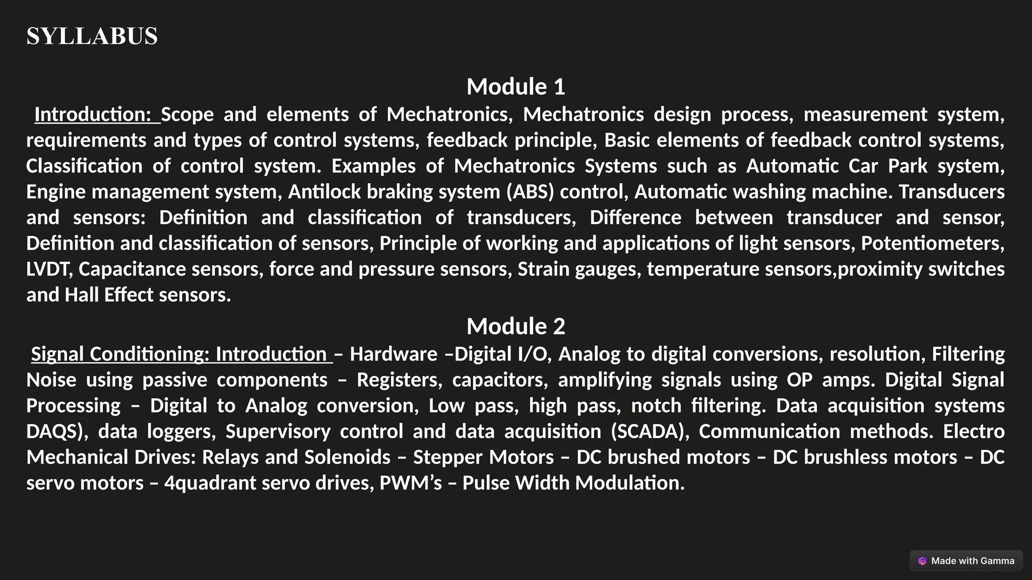
Module 1
Introduction: Scopeand elements of Mechatronics, Mechatronics design process, measurement system,
requirements and types of control systems, feedback principle, Basic elements of feedback control systems,
Classification of control system. Examples of Mechatronics Systems such as Automatic Car Park system,
Engine management system, Antilock braking system (ABS) control, Automatic washing machine. Transducers
and sensors: Definition and classification of transducers, Difference between transducer and sensor,
Definition and classification of sensors, Principle of working and applications of light sensors, Potentiometers,
LVDT, Capacitance sensors, force and pressure sensors, Strain gauges, temperature sensors,proximity switches
and Hall Effect sensors.
Module 2
Signal Conditioning: Introduction – Hardware –Digital I/O, Analog to digital conversions, resolution, Filtering
Noise using passive components – Registers, capacitors, amplifying signals using OP amps. Digital Signal
Processing – Digital to Analog conversion, Low pass, high pass, notch filtering. Data acquisition systems
DAQS), data loggers, Supervisory control and data acquisition (SCADA), Communication methods. Electro
Mechanical Drives: Relays and Solenoids – Stepper Motors – DC brushed motors – DC brushless motors – DC
servo motors – 4quadrant servo drives, PWM’s – Pulse Width Modulation.
3.
SYLLABUS
Module 3
Microprocessor &Microcontrollers: Introduction, Microprocessor systems, Basic elements of control systems,
Microcontrollers, Difference between Microprocessor and Microcontrollers. Microprocessor Architecture:
Microprocessor architecture and terminology CPU, memory and address, I/O and Peripheral devices, ALU,
Instruction and Program, Assembler, Data Registers, Program Counter, Flags, Fetch cycle, write cycle, state,
bus interrupts. Intel’s 8085A Microprocessor.
Module 4
Programmable Logic Controller: Introduction to PLCs, Basic structure of PLC, Principle of operation, input and
output processing, PLC programming language, ladder diagram, ladder diagrams circuits, timer counters,
internal relays, master control, jump control, shift registers, data handling, and manipulations, analogue input
and output, selection of PLC for application. Application of PLC control: Extending and retracting a pneumatic
piston using latches, control of two pneumatic pistons, control of process motor, control of vibrating machine,
control of process tank, control of conveyer motor etc.
4.
SYLLABUS
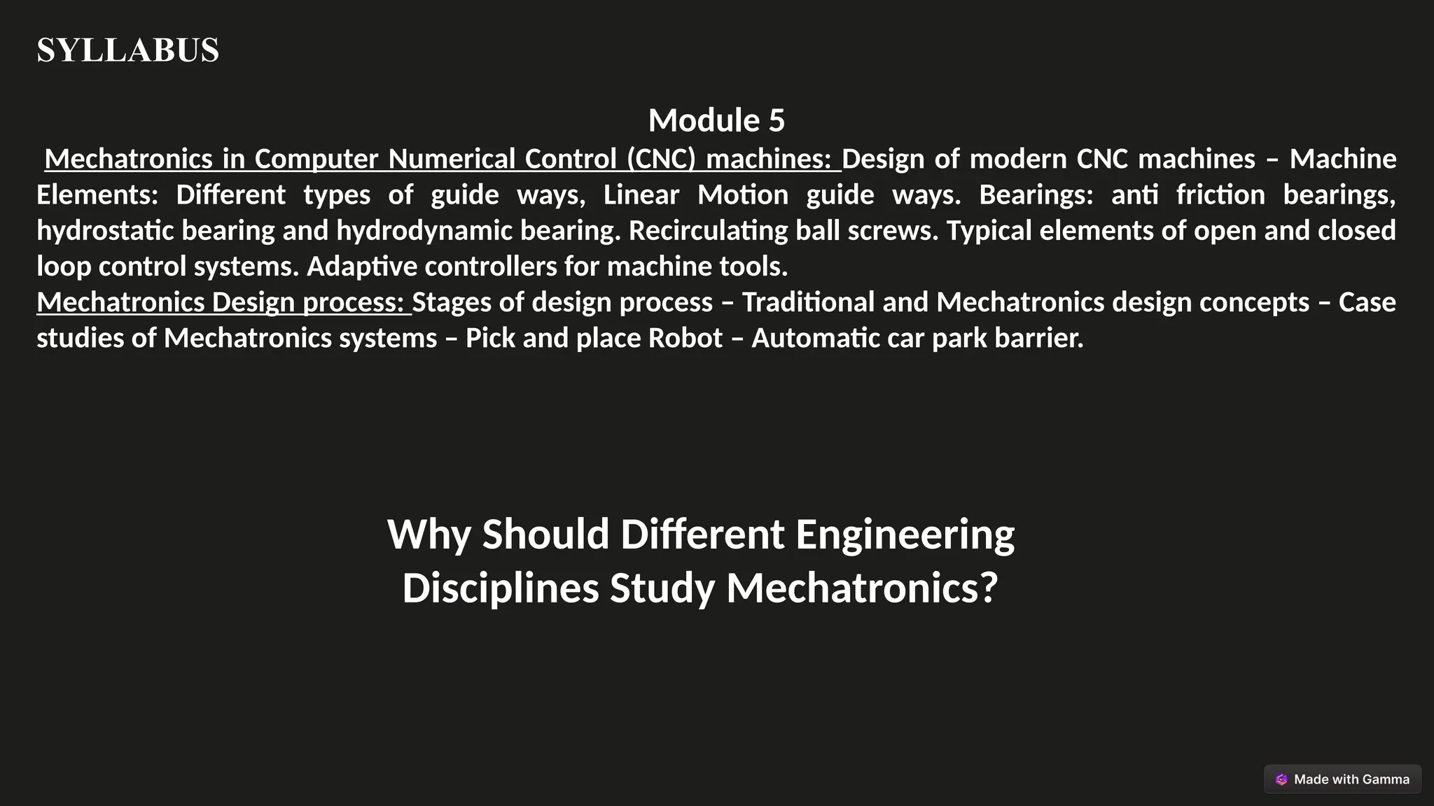
Module 5
Mechatronics inComputer Numerical Control (CNC) machines: Design of modern CNC machines – Machine
Elements: Different types of guide ways, Linear Motion guide ways. Bearings: anti friction bearings,
hydrostatic bearing and hydrodynamic bearing. Recirculating ball screws. Typical elements of open and closed
loop control systems. Adaptive controllers for machine tools.
Mechatronics Design process: Stages of design process – Traditional and Mechatronics design concepts – Case
studies of Mechatronics systems – Pick and place Robot – Automatic car park barrier.
Why Should Different Engineering
Disciplines Study Mechatronics?
5.
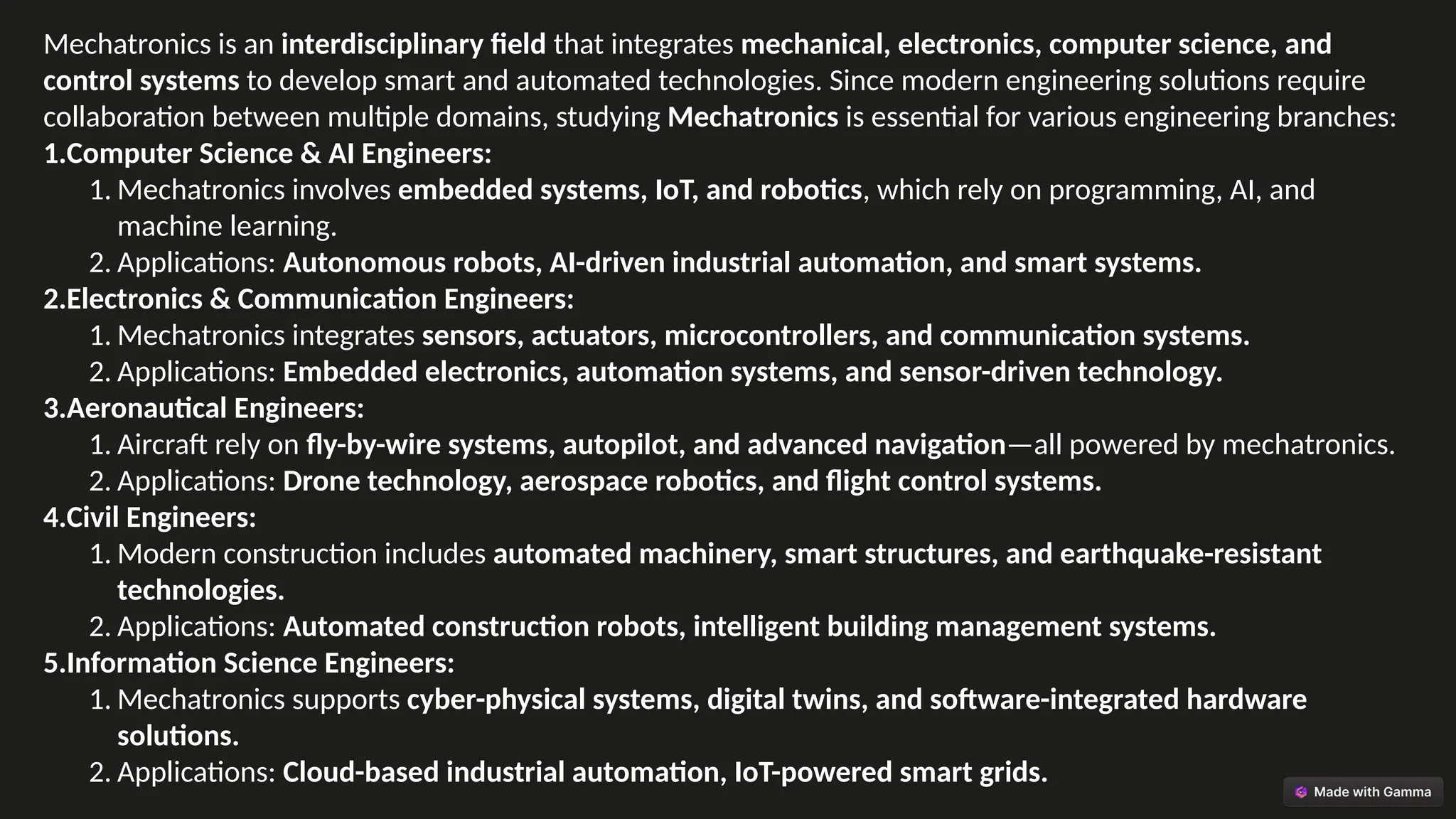
Mechatronics is aninterdisciplinary field that integrates mechanical, electronics, computer science, and
control systems to develop smart and automated technologies. Since modern engineering solutions require
collaboration between multiple domains, studying Mechatronics is essential for various engineering branches:
1.Computer Science & AI Engineers:
1. Mechatronics involves embedded systems, IoT, and robotics, which rely on programming, AI, and
machine learning.
2. Applications: Autonomous robots, AI-driven industrial automation, and smart systems.
2.Electronics & Communication Engineers:
1. Mechatronics integrates sensors, actuators, microcontrollers, and communication systems.
2. Applications: Embedded electronics, automation systems, and sensor-driven technology.
3.Aeronautical Engineers:
1. Aircraft rely on fly-by-wire systems, autopilot, and advanced navigation—all powered by mechatronics.
2. Applications: Drone technology, aerospace robotics, and flight control systems.
4.Civil Engineers:
1. Modern construction includes automated machinery, smart structures, and earthquake-resistant
technologies.
2. Applications: Automated construction robots, intelligent building management systems.
5.Information Science Engineers:
1. Mechatronics supports cyber-physical systems, digital twins, and software-integrated hardware
solutions.
2. Applications: Cloud-based industrial automation, IoT-powered smart grids.
6.
COURSE OUTCOMES
CO 1:Understand mechatronic systems, its relevance in engineering design and differentiate
between various sensors, transducers and actuators and their applications.
CO 2: Explain the fundamental concepts of signal conditioning, data acquisition systems, and
electromechanical drives
CO 3: Understand the functions of micro controllers and Microprocessor Architecture
CO 4: Explain the fundamental concepts of PLC programming, including ladder diagrams, timers,
counters, and internal relays.
CO 5: Interpret the design of modern CNC machines and their key components, including
guideways, linear motion guideways, and bearings.
7.
What is Mechatronics?Core Elements Defined
Mechanical Systems
The backbone of physical
action. Gears, motors, and
structural components are
key.
Electronic Systems
Circuits, sensors, and
microcontrollers enable
intelligent control and
processing.
Control Systems
Algorithms managing
system behavior. Feedback
loops are vital for
precision.
Computer Systems
Process data and execute
control algorithms. Enable
automated decision-
making.
8.
Mechatronics is amultidisciplinary engineering field that integrates
mechanical, electrical, electronics, computer science, and control systems
to create intelligent and automated solutions. Its applications span across
various industries:
1.Industrial Automation – Robotics, CNC machines, automated assembly lines.
2.Automotive Systems – ABS, engine management, adaptive cruise control.
3.Aerospace & Defense – Autopilot systems, UAVs, flight control systems.
4.Medical Devices – Robotic surgery, prosthetics, diagnostic equipment.
5.Consumer Electronics – Smart home devices, wearable technology.
6.Agriculture & Construction – Precision farming, autonomous machinery.
Scope of Mechatronics
9.
The Mechatronics Design
Process:A Step-by-Step Guide
Requirements
Define project needs and goals.
System Design
Conceptualize integrated solutions.
Prototyping
Build and test the system.
Implementation
Deploy final product.
10.
Mechatronics Design Process,Measurement System, and Control
Systems
1. Mechatronics Design Process
The Mechatronics design process follows a systematic approach to integrating mechanical,
electrical, and software components:
1.Problem Identification – Define system requirements and objectives.
2.Conceptual Design – Develop design ideas and component selection.
3.Modeling & Simulation – Use software (MATLAB, SolidWorks) for virtual testing.
4.Prototype Development – Build a functional model for validation.
5.Testing & Optimization – Refine performance based on feedback.
6.Implementation & Maintenance – Deploy and monitor the system in real-world
conditions.
📌 Example: Developing an automated robotic arm for assembly lines.
11.
Mechatronics Design Process
TheMechatronics Design Process is a structured methodology used to develop intelligent
systems by integrating mechanical, electrical, and software components. It ensures efficiency,
reliability, and automation in various applications.
1. Problem Identification – Define System
Requirements and Objectives
This step involves identifying the problem, defining project goals, and
setting system requirements based on functional needs.
📌 Example:
Developing an automated robotic arm for an assembly line.
•Problem: Manual assembly is slow and error-prone.
•Objective: Design a robotic arm that increases efficiency, reduces
human error, and operates with precision.
•System Requirements:
•Must pick and place objects with ±0.5 mm accuracy.
•Should integrate with a PLC-based control system.
•Needs to handle objects up to 2 kg.
2. Conceptual Design – Develop Design Ideas &
Component Selection
At this stage, engineers brainstorm different design solutions
and select suitable components.
📌 Example:
For a robotic arm, the conceptual design includes:
•Mechanical Structure: Decide on the number of joints and
degrees of freedom.
•Actuators: Selection of servo motors for precise motion.
•Sensors: Use of force sensors for grip control.
•Controllers: Implementation of a microcontroller or PLC.
•Power Source: Electrical or pneumatic system
12.
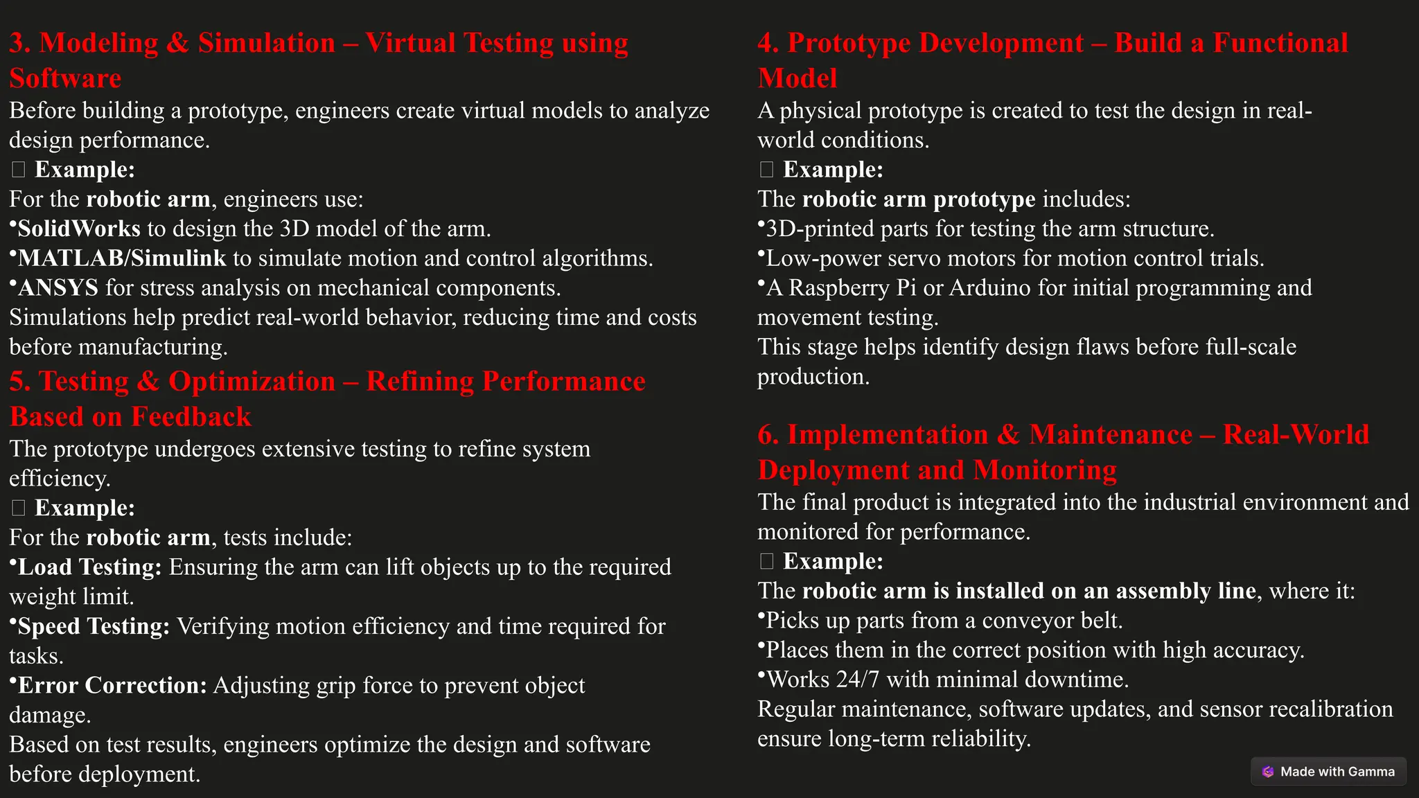
3. Modeling &Simulation – Virtual Testing using
Software
Before building a prototype, engineers create virtual models to analyze
design performance.
📌 Example:
For the robotic arm, engineers use:
•SolidWorks to design the 3D model of the arm.
•MATLAB/Simulink to simulate motion and control algorithms.
•ANSYS for stress analysis on mechanical components.
Simulations help predict real-world behavior, reducing time and costs
before manufacturing.
4. Prototype Development – Build a Functional
Model
A physical prototype is created to test the design in real-
world conditions.
📌 Example:
The robotic arm prototype includes:
•3D-printed parts for testing the arm structure.
•Low-power servo motors for motion control trials.
•A Raspberry Pi or Arduino for initial programming and
movement testing.
This stage helps identify design flaws before full-scale
production.
5. Testing & Optimization – Refining Performance
Based on Feedback
The prototype undergoes extensive testing to refine system
efficiency.
📌 Example:
For the robotic arm, tests include:
•Load Testing: Ensuring the arm can lift objects up to the required
weight limit.
•Speed Testing: Verifying motion efficiency and time required for
tasks.
•Error Correction: Adjusting grip force to prevent object
damage.
Based on test results, engineers optimize the design and software
before deployment.
6. Implementation & Maintenance – Real-World
Deployment and Monitoring
The final product is integrated into the industrial environment and
monitored for performance.
📌 Example:
The robotic arm is installed on an assembly line, where it:
•Picks up parts from a conveyor belt.
•Places them in the correct position with high accuracy.
•Works 24/7 with minimal downtime.
Regular maintenance, software updates, and sensor recalibration
ensure long-term reliability.
13.
Measurement Systems:
Accuracy, Precision,and
Applications
1 Accuracy
How close to the real value?
2 Precision
Repeatability of
measurements.
3 Resolution
Smallest detectable change.
14.
Control Systems: Open-Loopvs. Closed-Loop
Open-Loop
Simple, no feedback. Output not monitored.
Closed-Loop
Uses feedback. Corrects errors in real-time.
15.
Feedback Principle: TheHeart of Control
Sensor
Measures output.
1
Controller
Analyzes error.
2
Actuator
Adjusts system.
3
16.
Mechatronics in Action:
Examplesand Case Studies
Robotics
Automated manufacturing.
Aerospace
Flight control systems.
Automotive
Engine management.
Healthcare
Medical devices.
17.
Conclusion: The Futureof
Mechatronics
Mechatronics is driving innovation. Expect smarter, more efficient
systems. It is key to automation and AI integration. Mechatronics will
shape future tech.
18.
Automatic Car Parksystem
Car parks use sensors and controllers to guide cars. Systems optimize space and improve traffic. Automation enhances
parking efficiency.
19.
Antilock braking system
(ABS)Control
ABS prevents wheel
lockup. Sensors
monitor wheel speed.
A controller adjusts
brake pressure. This
maintains stability
and control.
Actuators precisely
manage braking.
Enhances safety on
roads.