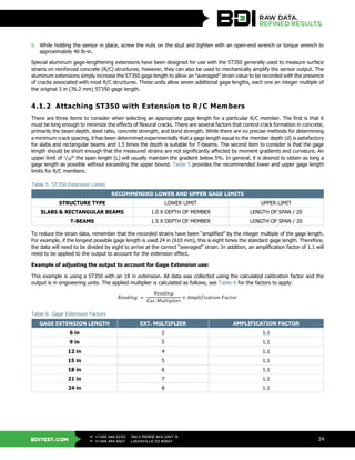
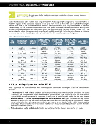
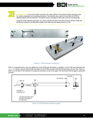
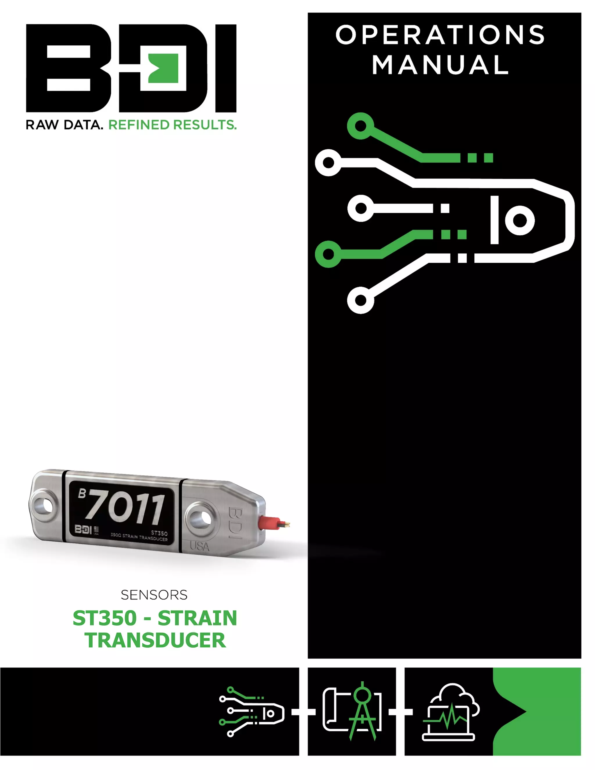
This document provides an operations manual for the ST350 strain transducer. It includes specifications, installation instructions, testing procedures, and maintenance guidelines. The manual has been revised multiple times to update specifications and reflect hardware and compliance changes. It provides warranty information and instructions for returning products for repair. Installation sections cover attaching the transducer to steel, concrete, timber and composite materials.

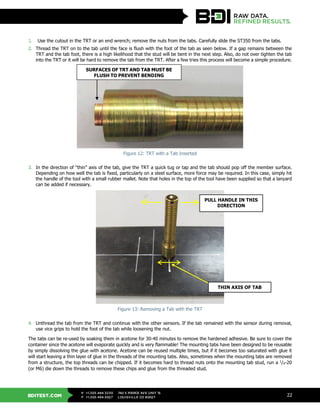
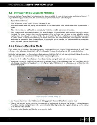
![BDITEST.COM
+1.303.494.3230
+1.303.494.5027
P
F
740 S PIERCE AVE UNIT 15
LOUISVILLE CO 80027
8
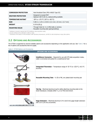
2. ST350 OVERVIEW
2.1 TECHNICAL SPECIFICATIONS
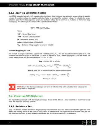
Figure 1: ST350 Drawing (inches)
Table 1: ST350 Specifications
MODEL ST350
TYPE 350Ω
CIRCUIT Full Wheatstone bridge with 4 active 350Ω strain gages
EXCITATION VOLTAGE +1.0 to +10.0 Vdc
OUTPUT mV level, ratiometric to Excitation Voltage
OFFSET < 1.5 mV at time and temperature of calibration
POWER RATING:
MAX
TYPICAL
INTELLIDUCER1
300 mW
72 mW @ +5.0 Vdc
13 mW @ +5.0 Vdc
STRAIN RANGE ±4,000 µε (Calibrated to ±2,000 µε)
FORCE REQUIRED FOR 1,000µε ~17 lb (~76N)
TYPICAL SENSITIVITY ~500 με/mVout/Vin
ACCURACY2
< ±1%
CALIBRATION
Individually calibrated using N.I.S.T.-traceable automated system.
Calibration curve & factor provided
THERMISTOR (OPTIONAL) 3 kΩ - NTC
EFFECTIVE GAGE LENGTH 3.0 in (76.2 mm) [Gage Extensions available for R/C structures]
CABLE
Custom lead cable length made to order:
IC-02-187 [22 AWG, 2 shielded pair, drain wire, red PVC jacket]
IC-02-250 [22 AWG, 2 shielded pair, drain wire, blue PVC jacket]
IC-03-250 [24 AWG, 3 shielded pair, drain wire, black PVC jacket]
HOUSING Machined 6061 Aluminum Alloy](https://image.slidesharecdn.com/manual-strain-transducer-st350-201511-rev-a-201120095437/85/Manual-strain-transducer-st350-201511-rev-a-8-320.jpg)