Download to read offline
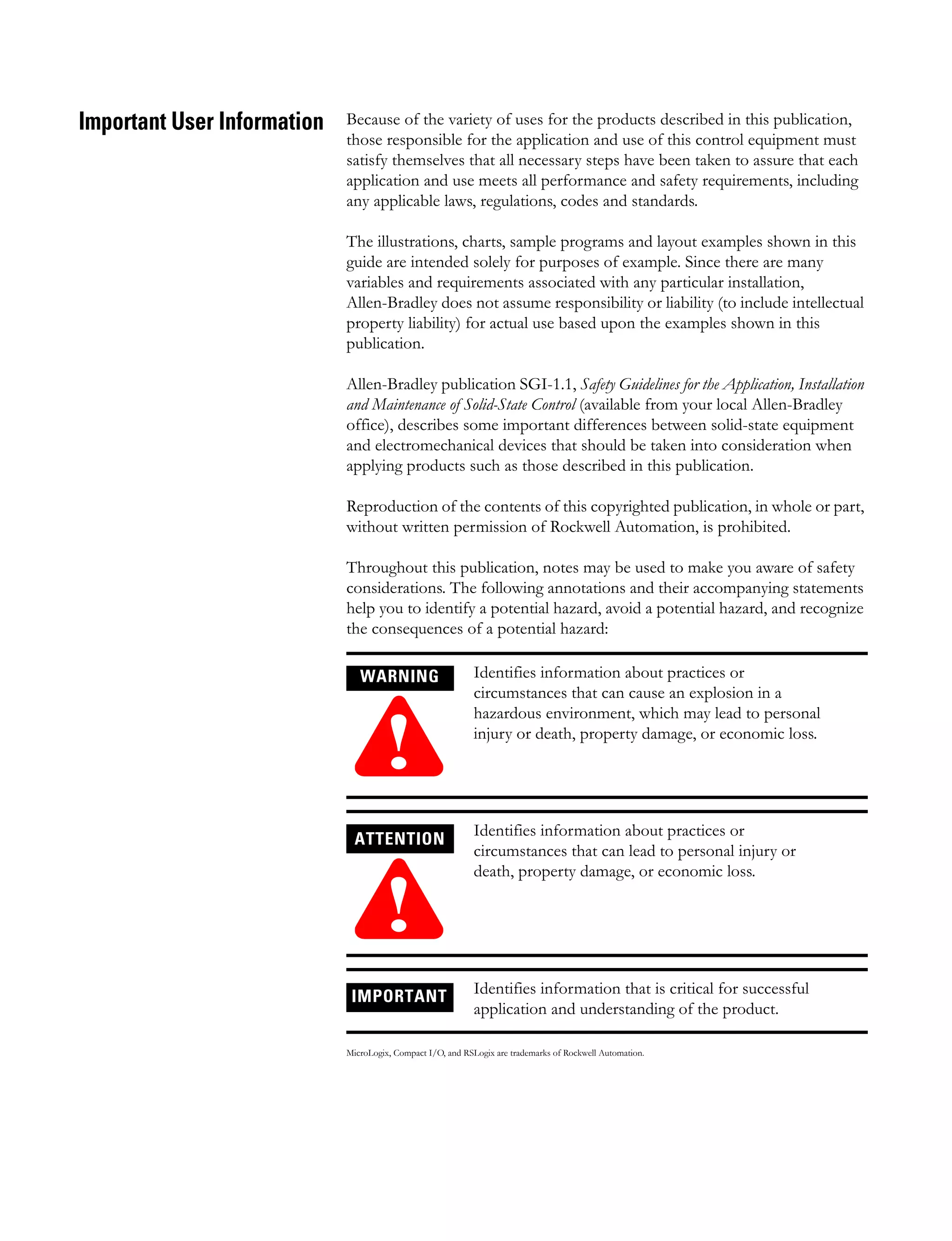


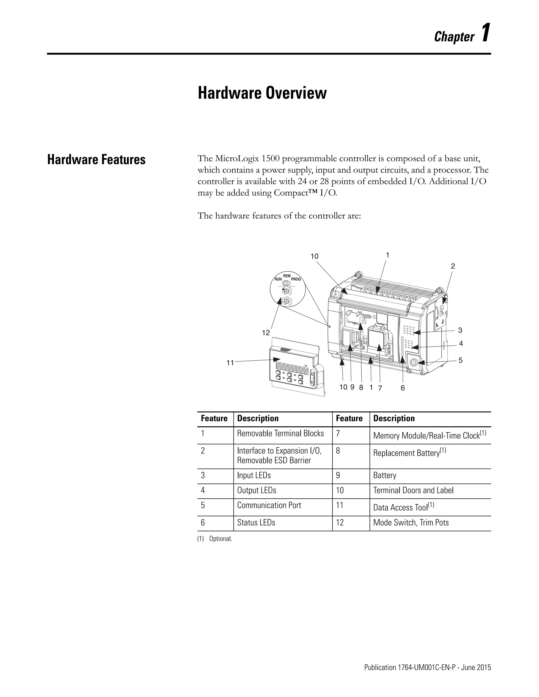
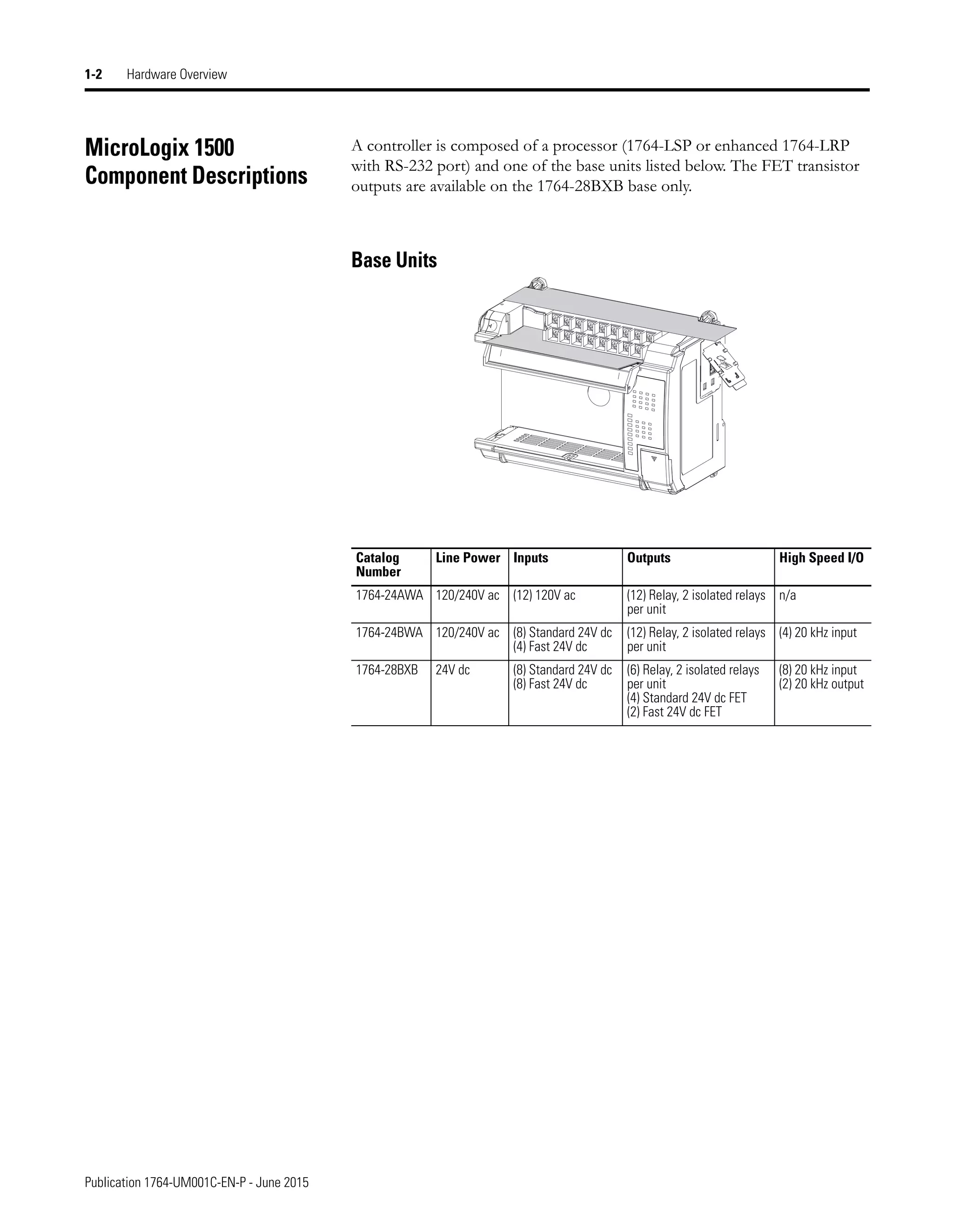
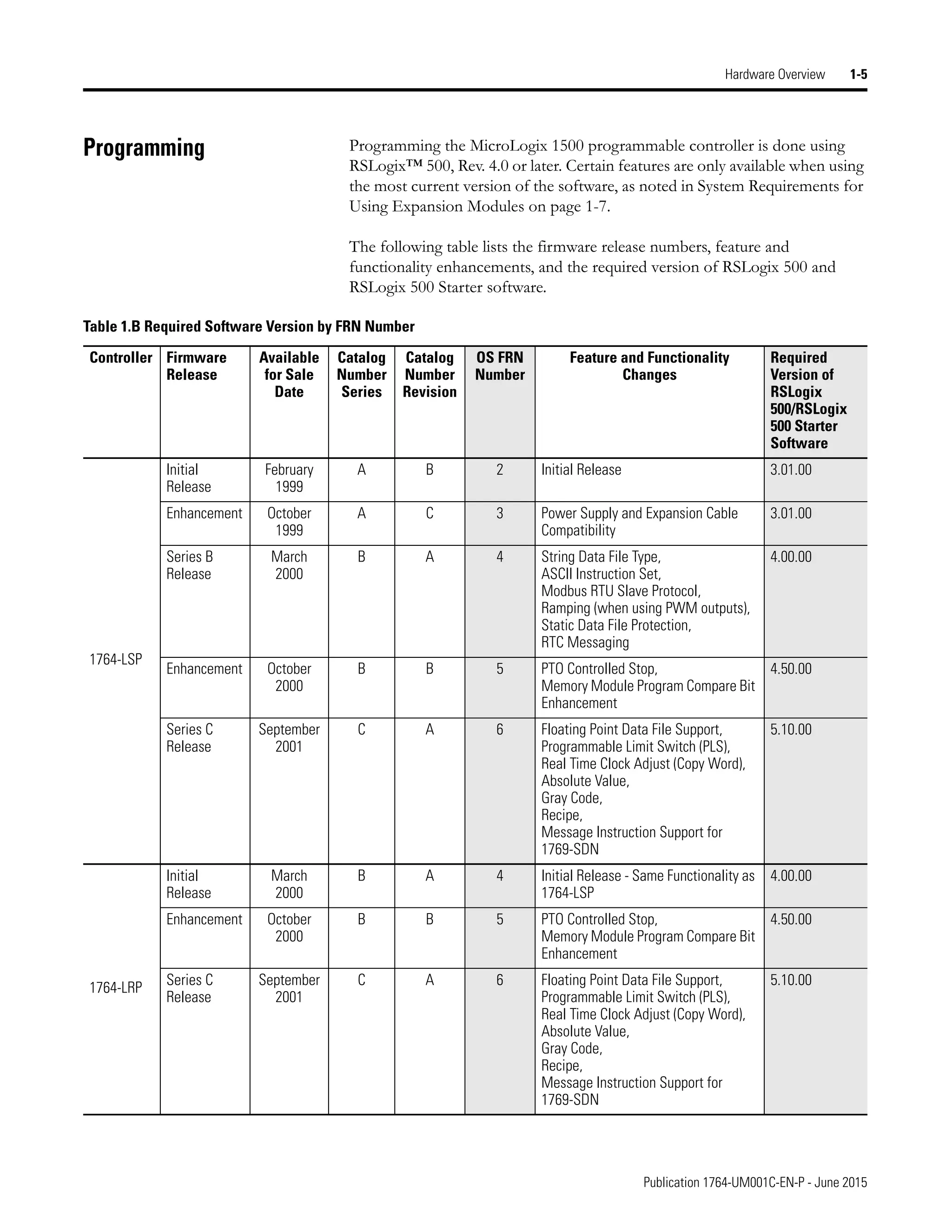
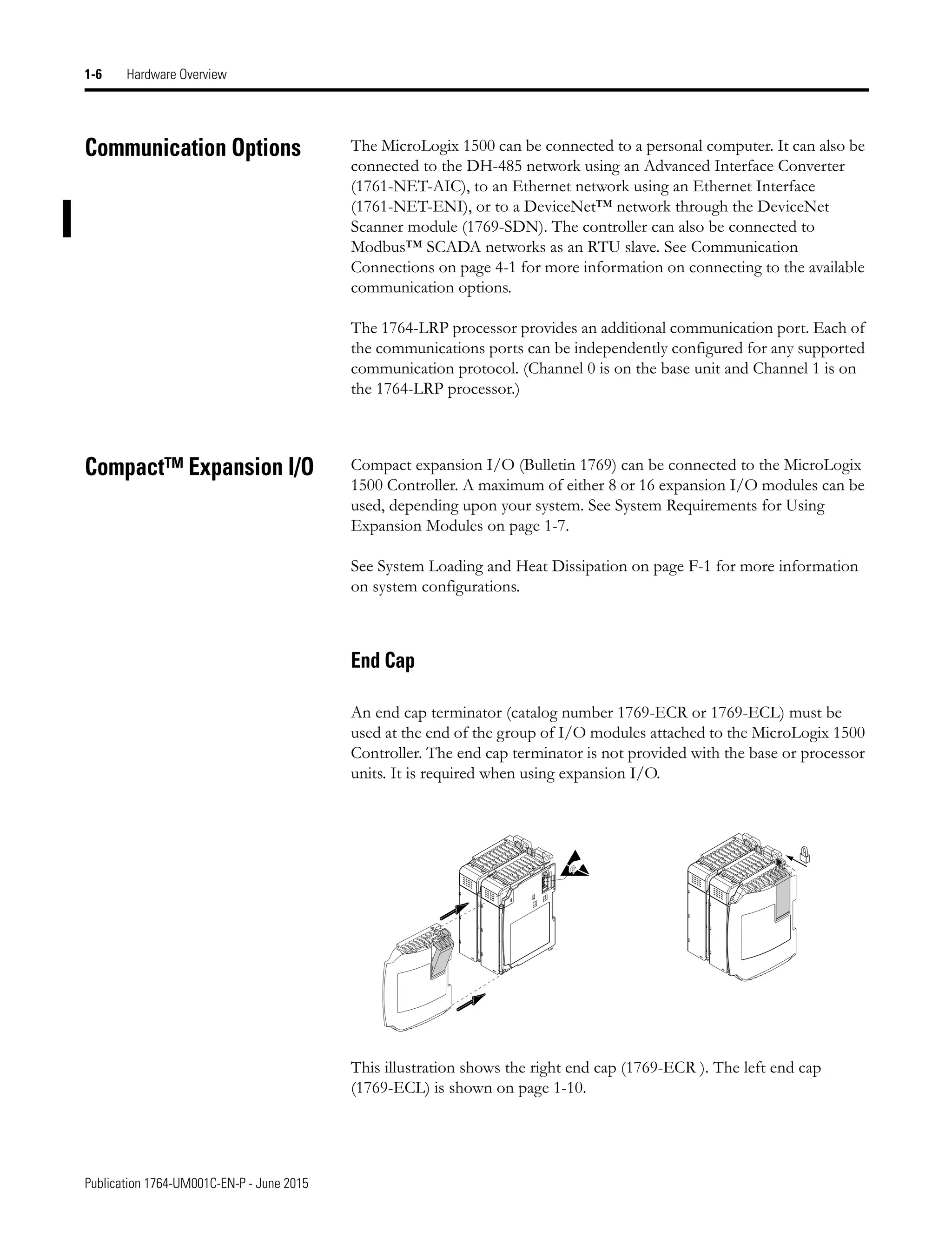
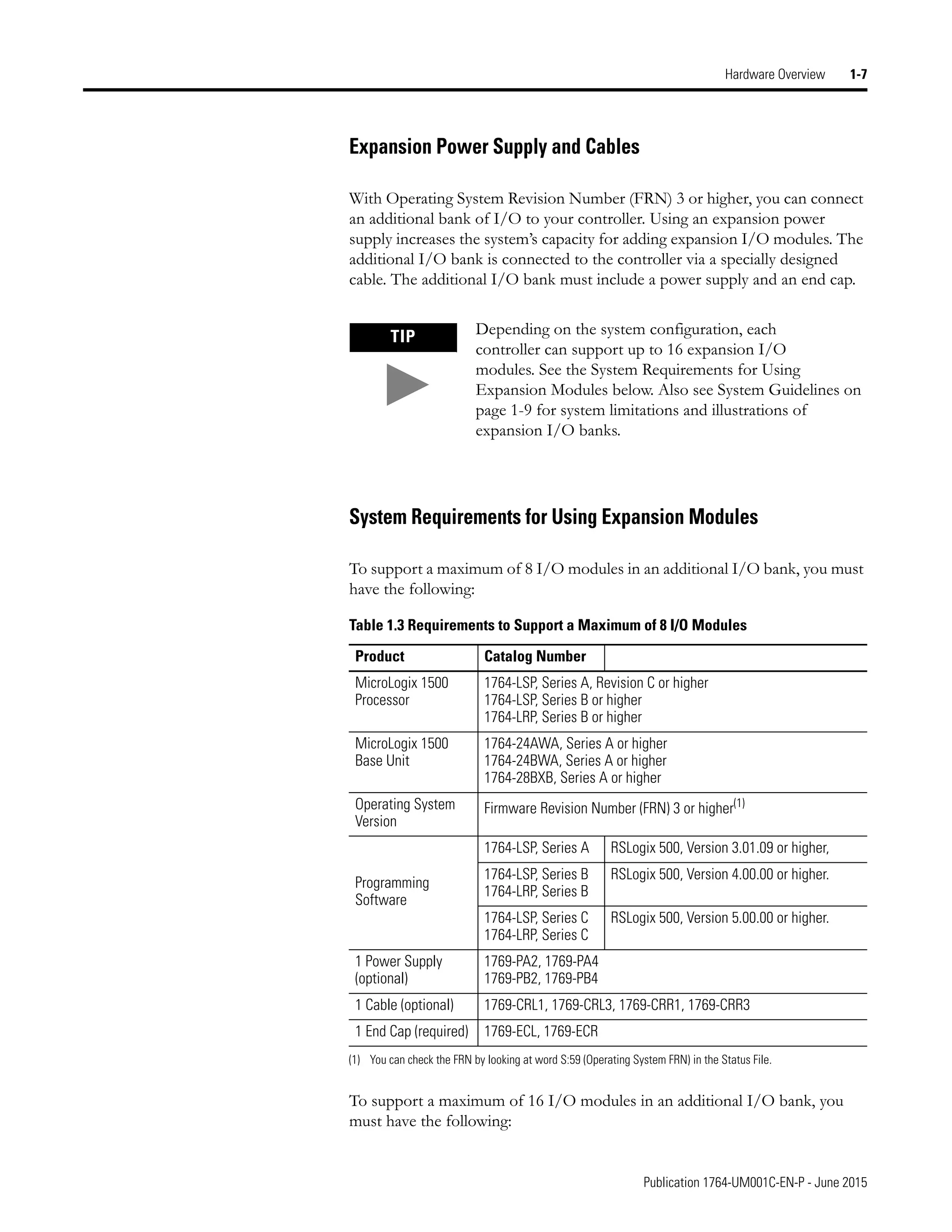
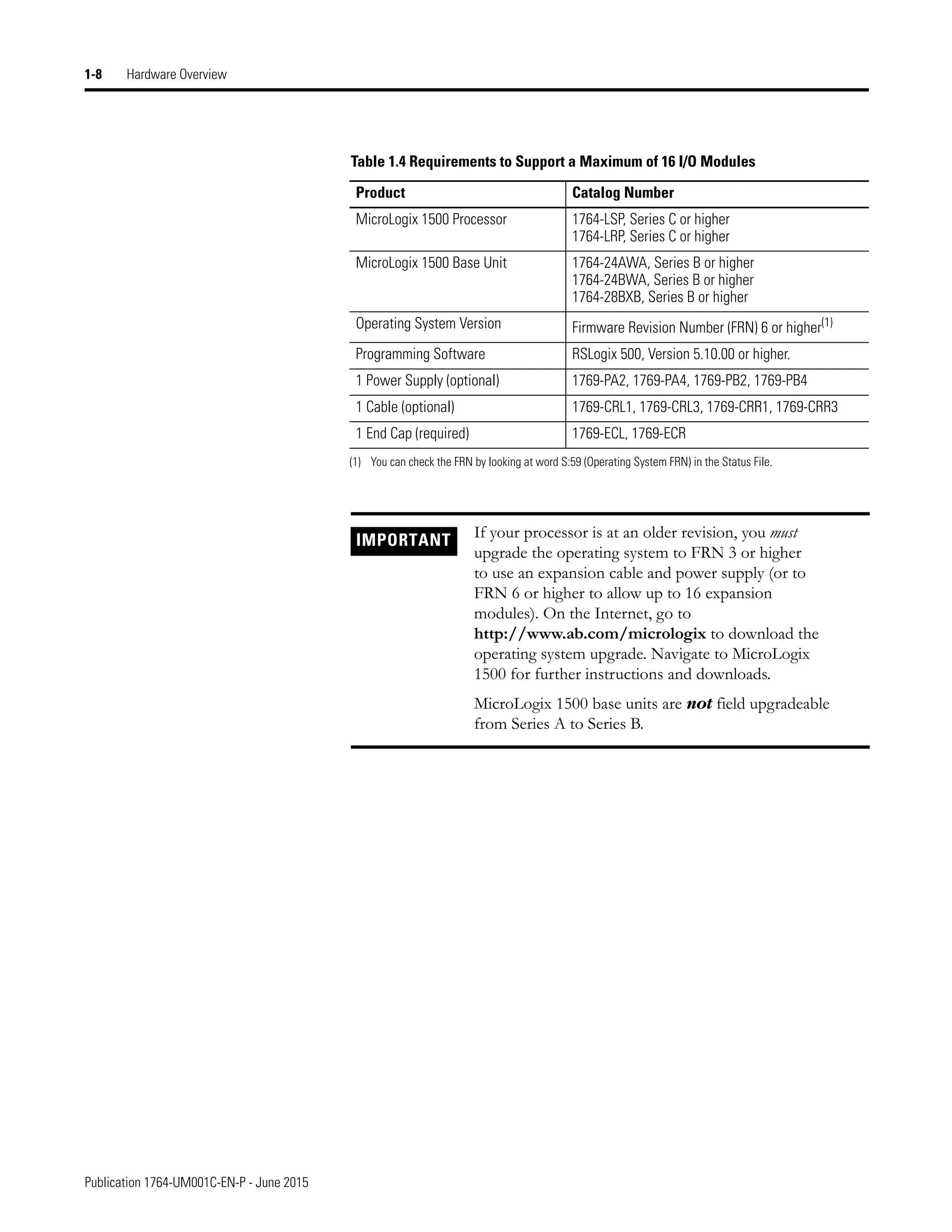


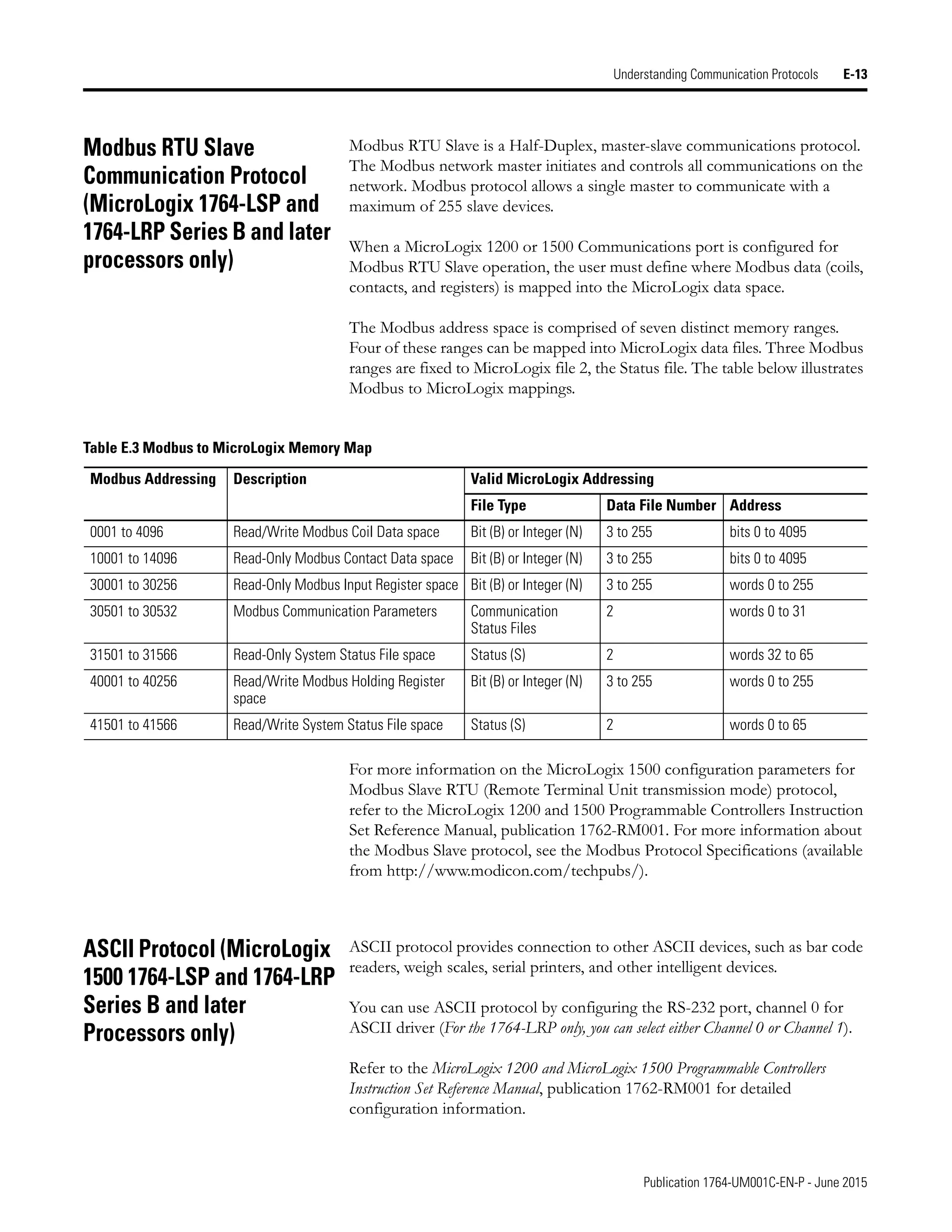
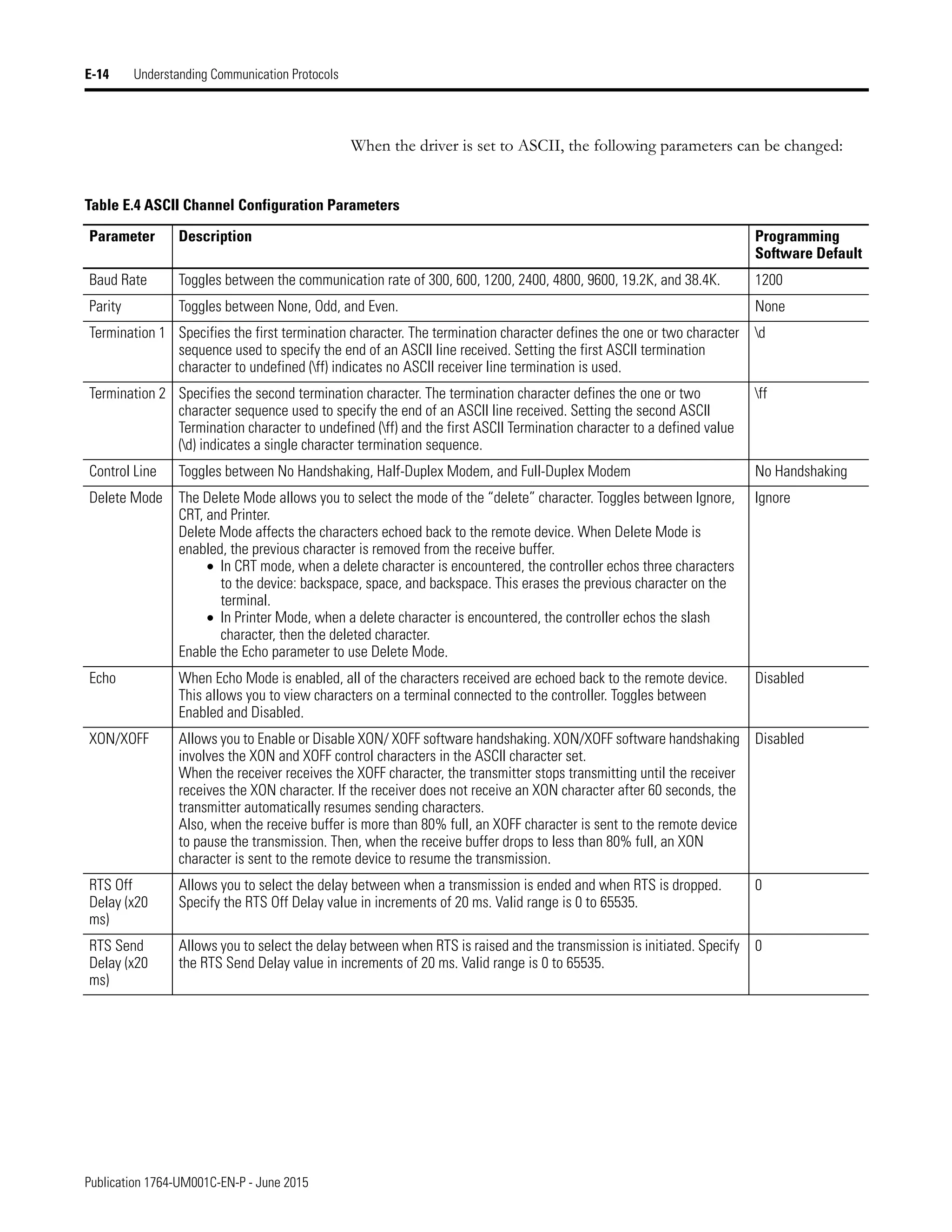
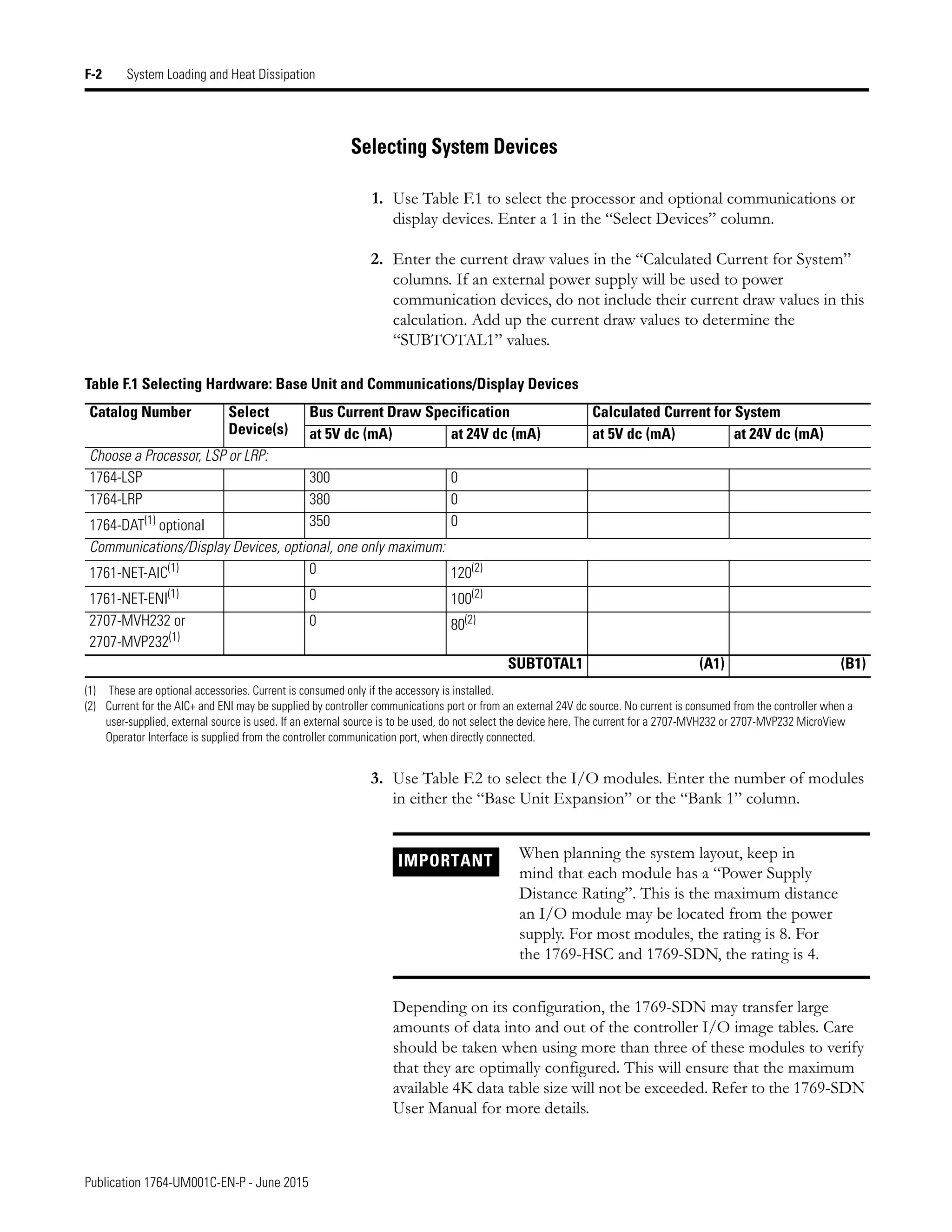


This document provides the user manual for MicroLogix 1500 programmable controllers. It contains important safety information and describes the hardware components, installation, wiring, and programming of MicroLogix 1500 controllers. The manual instructs users on agency certifications, safety considerations, mounting the controller, installing components, wiring requirements, and using expansion I/O modules. It is intended to guide users through setting up and implementing MicroLogix 1500 programmable logic controllers.


