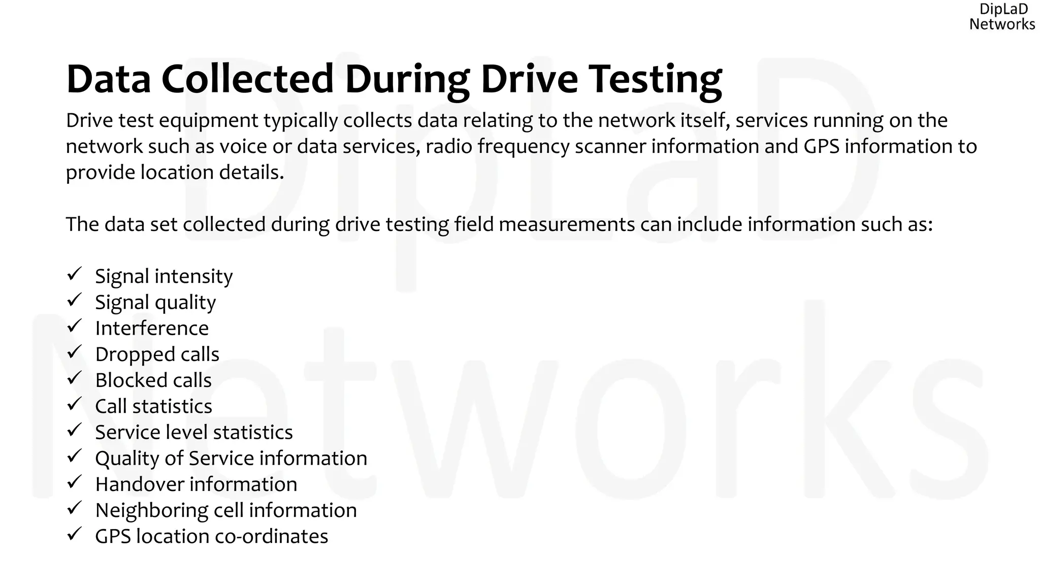
This document provides an overview of LTE drive testing, including:
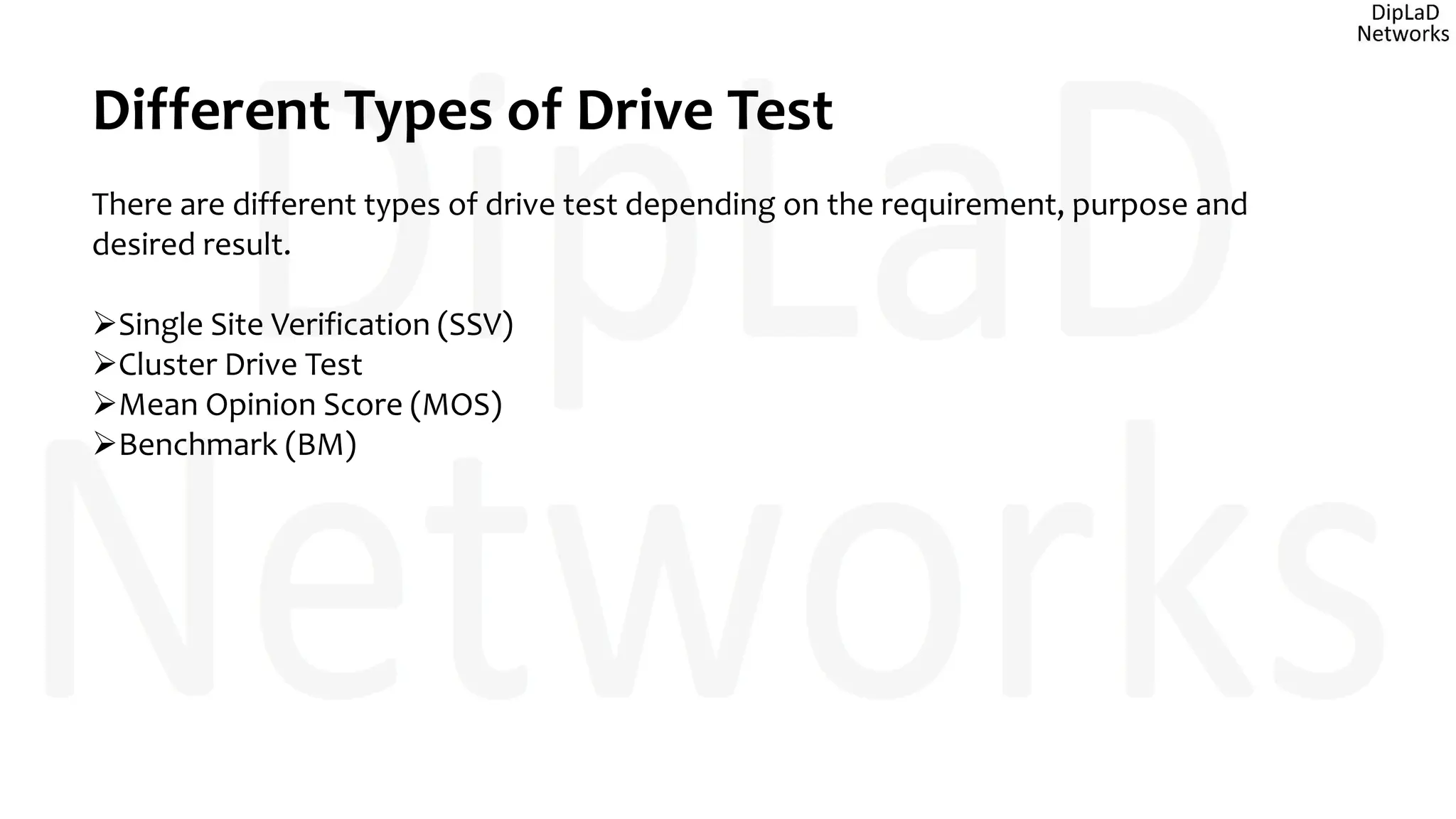
- The objectives and types of drive testing such as single site verification, cluster, and benchmark tests
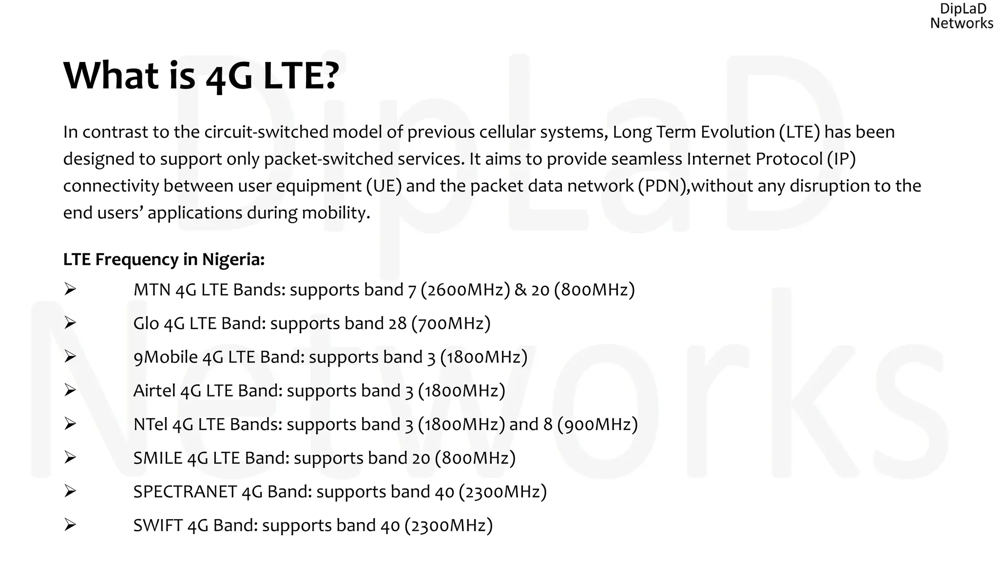
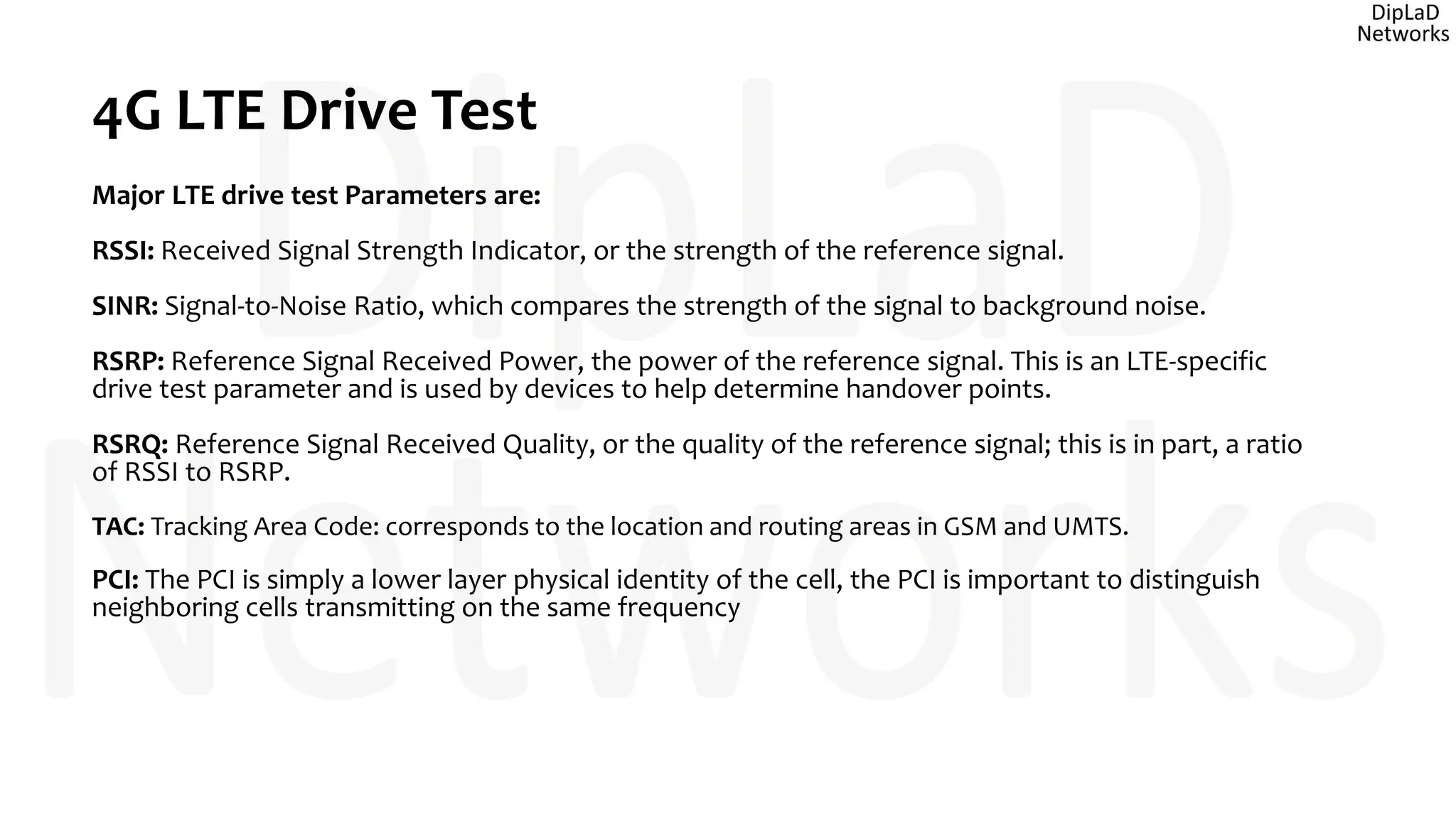
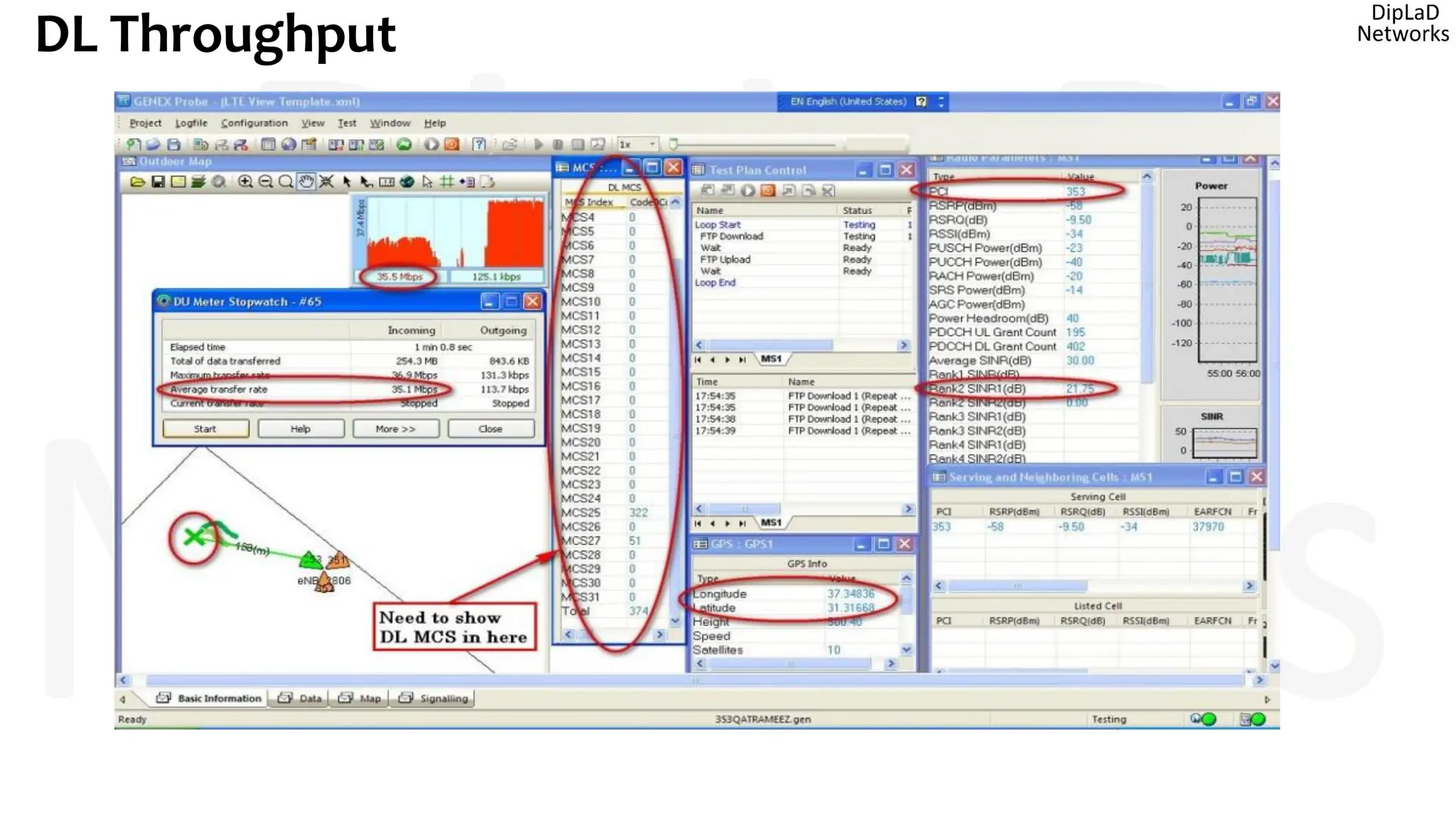
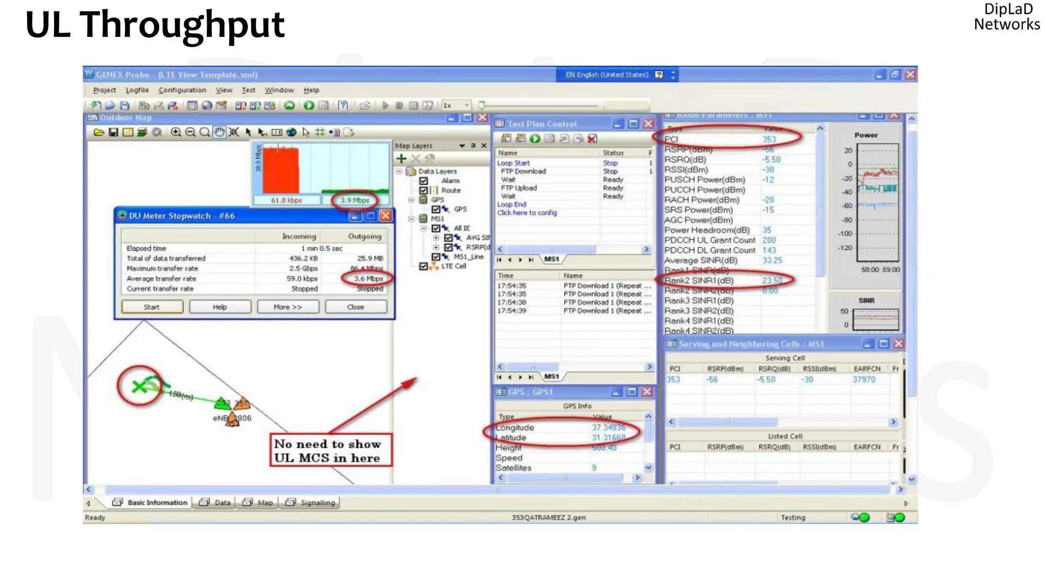
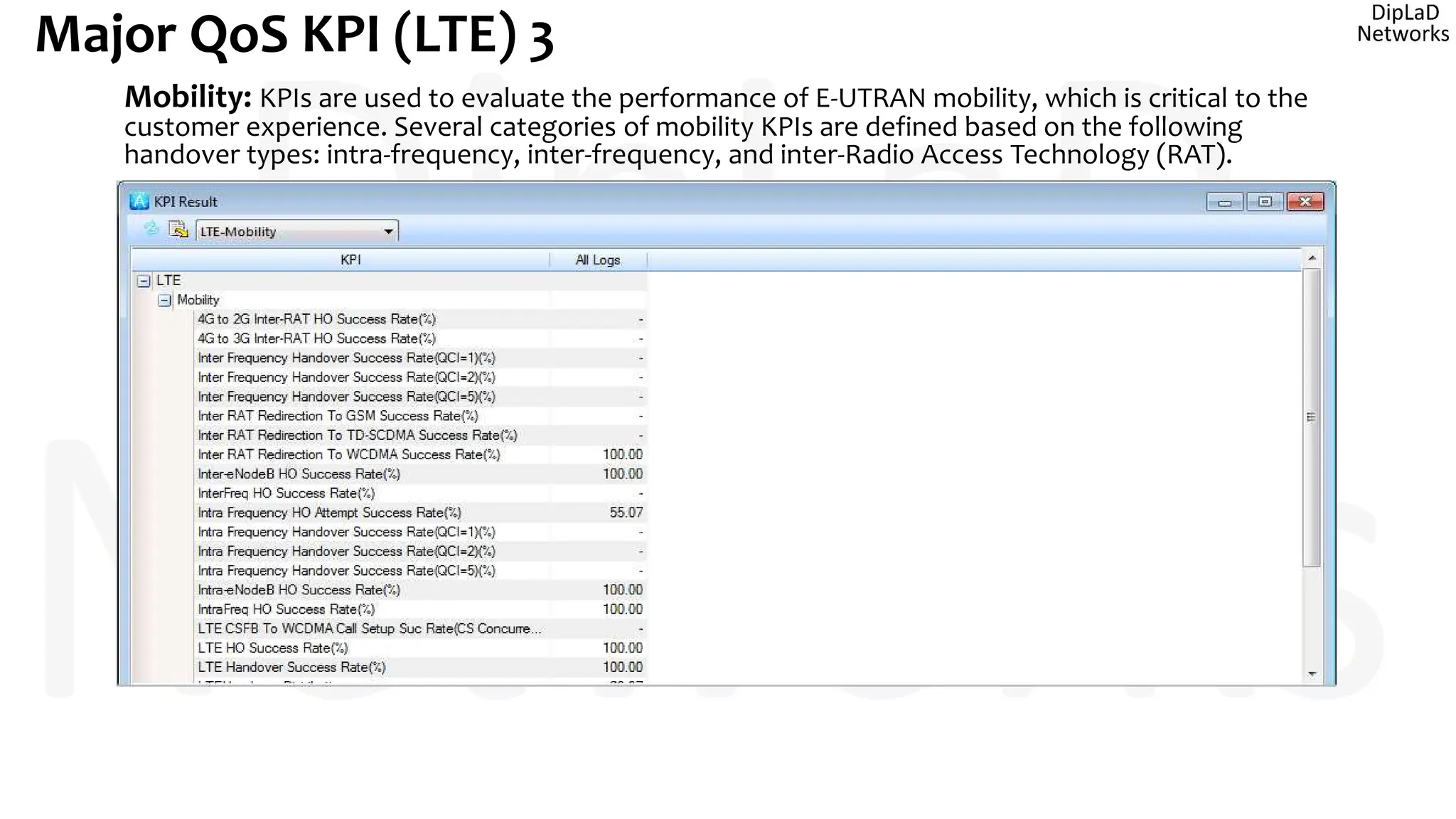
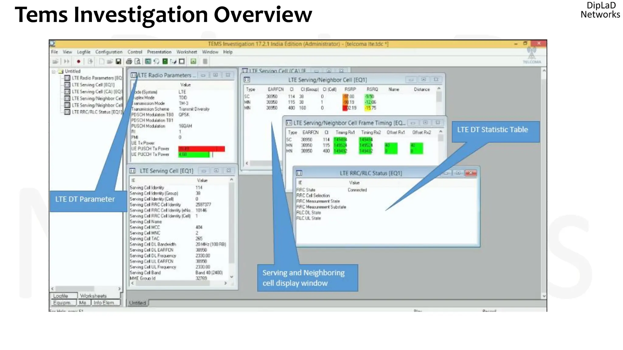
- The key parameters measured in 4G drive testing like RSSI, SINR, RSRP, and RSRQ
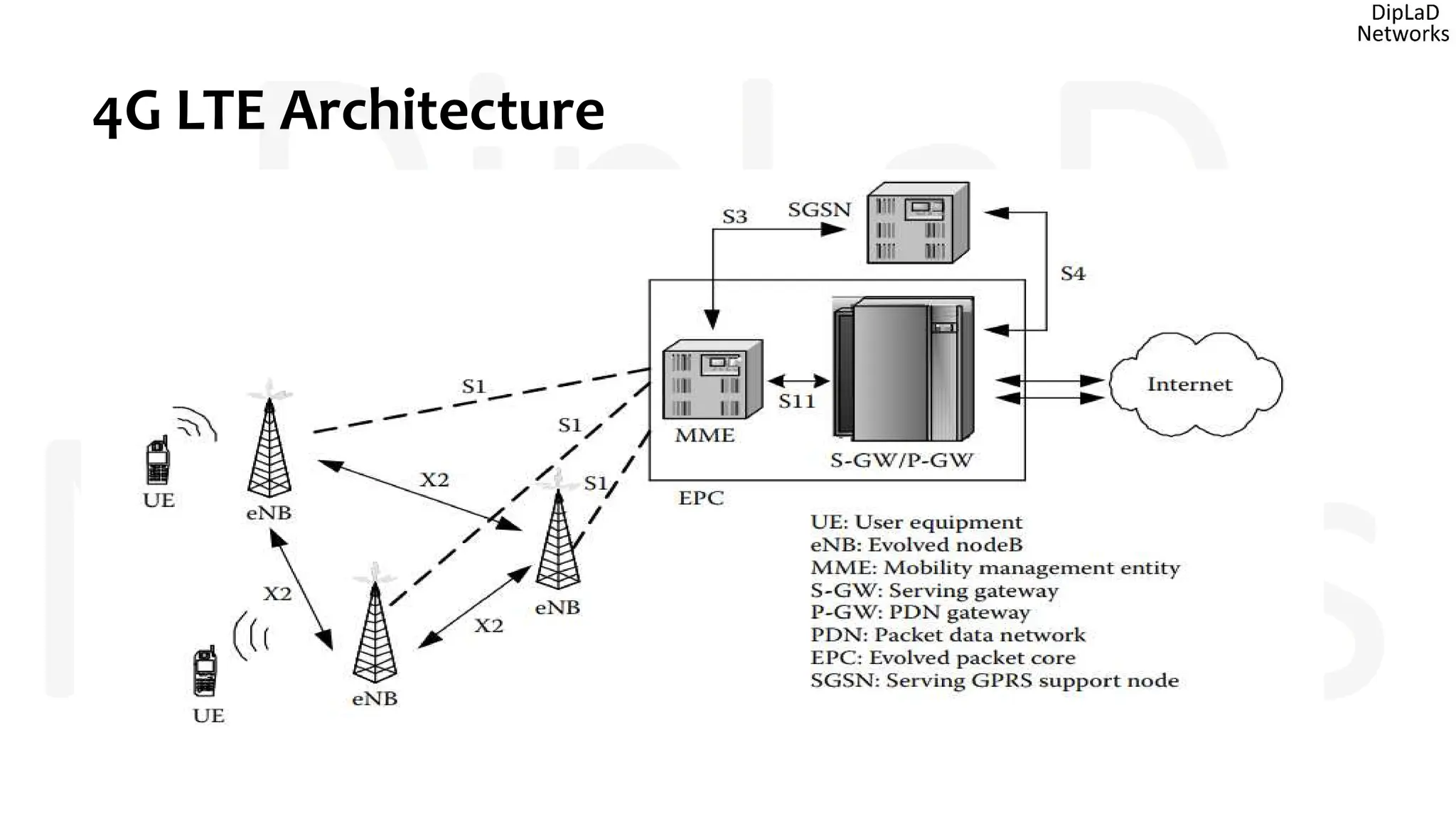
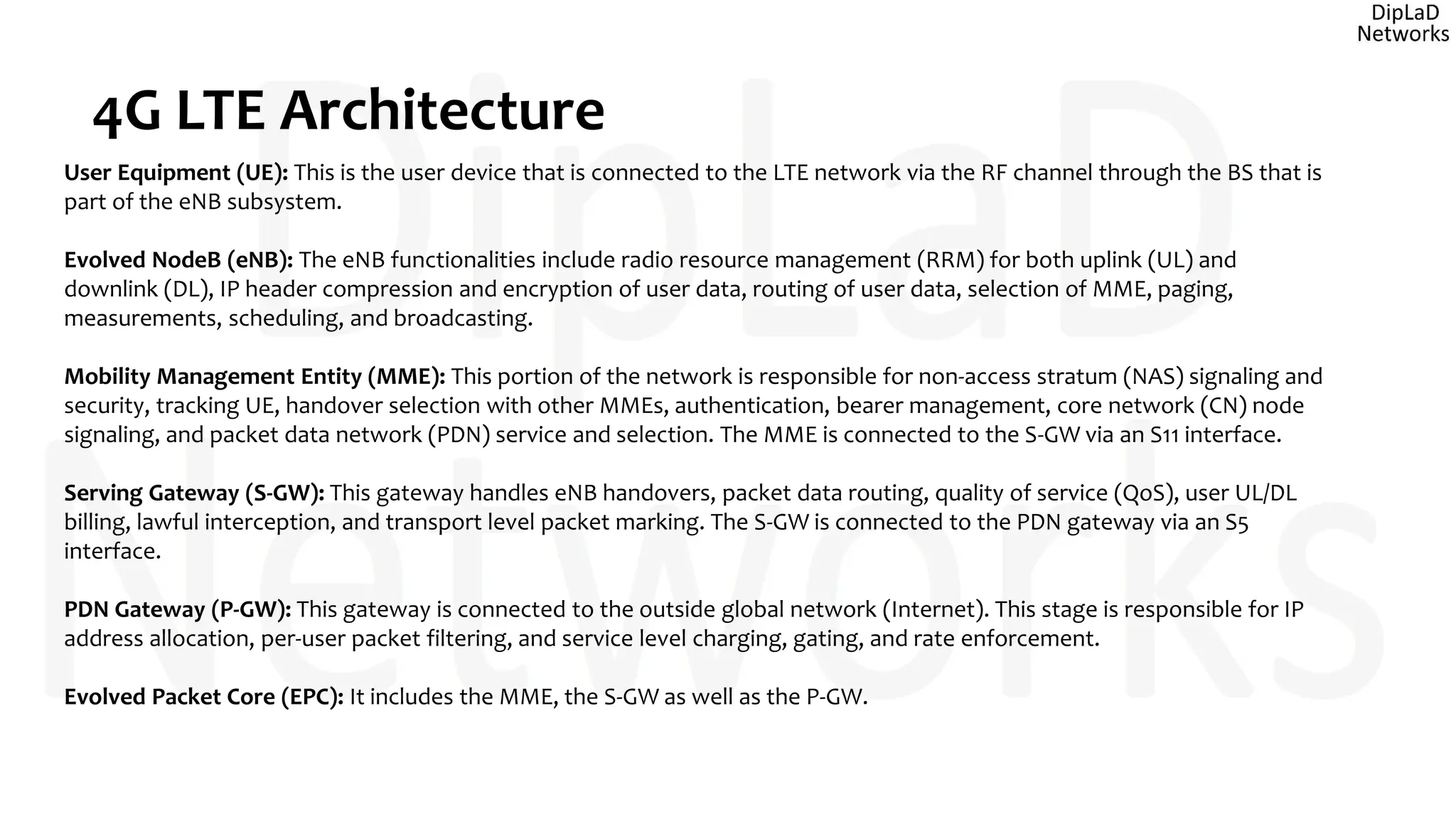
- An overview of the 4G LTE network architecture including components like the eNB, MME, S-GW, and P-GW
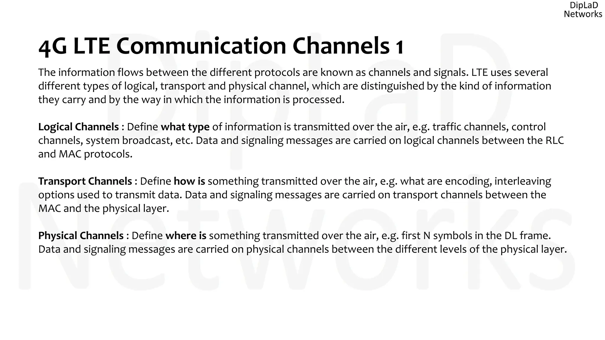
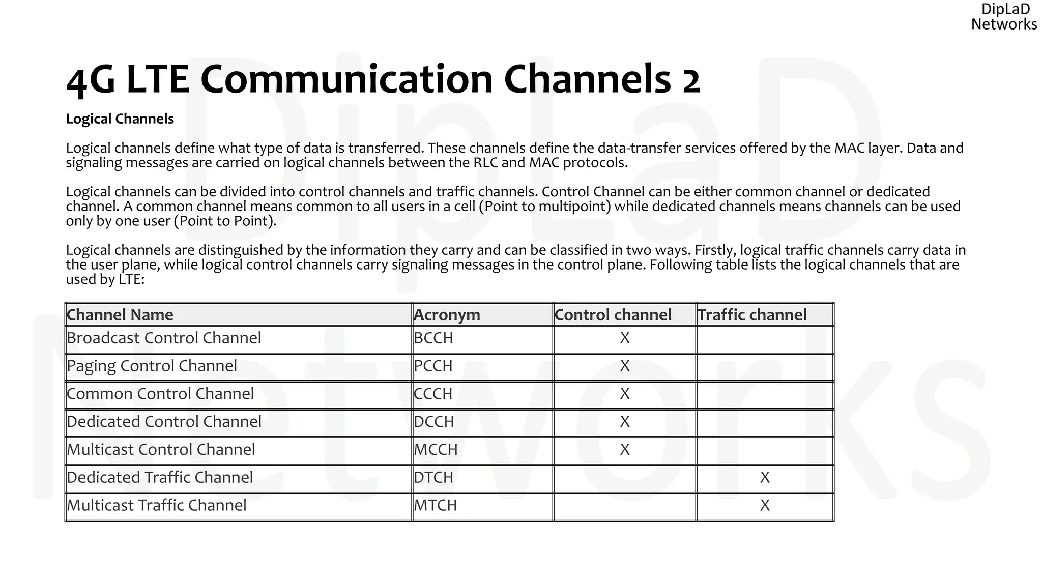
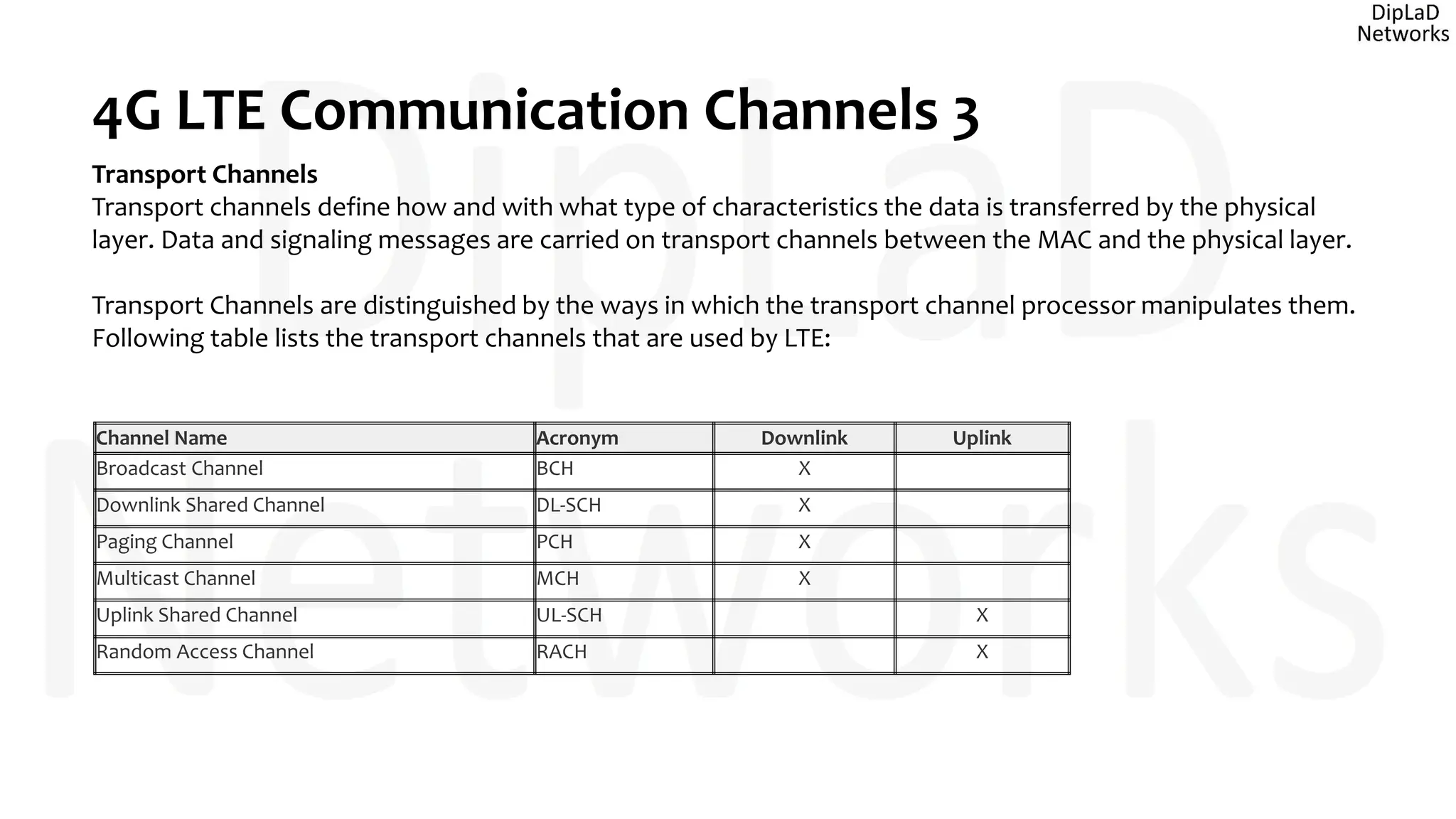
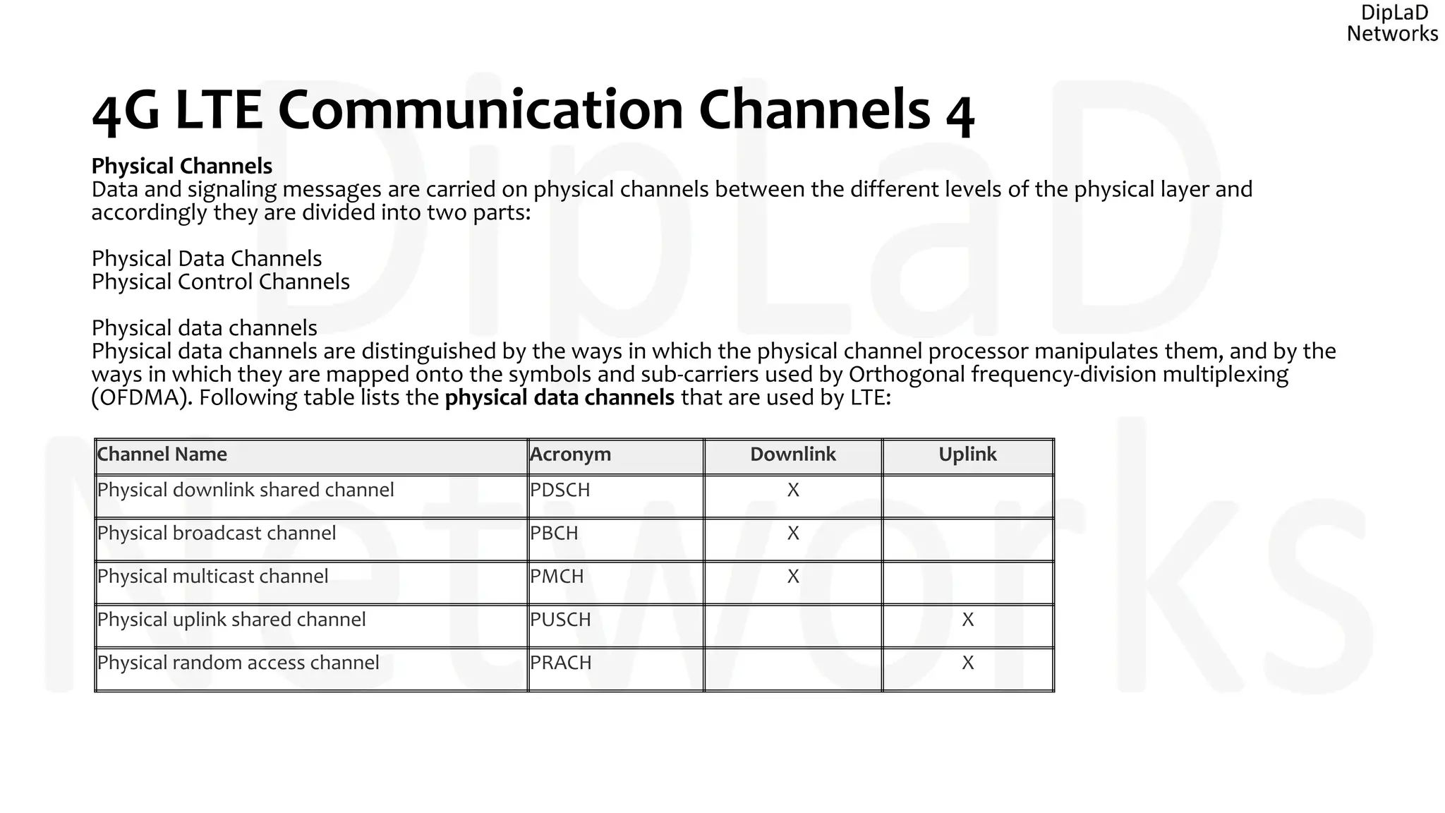
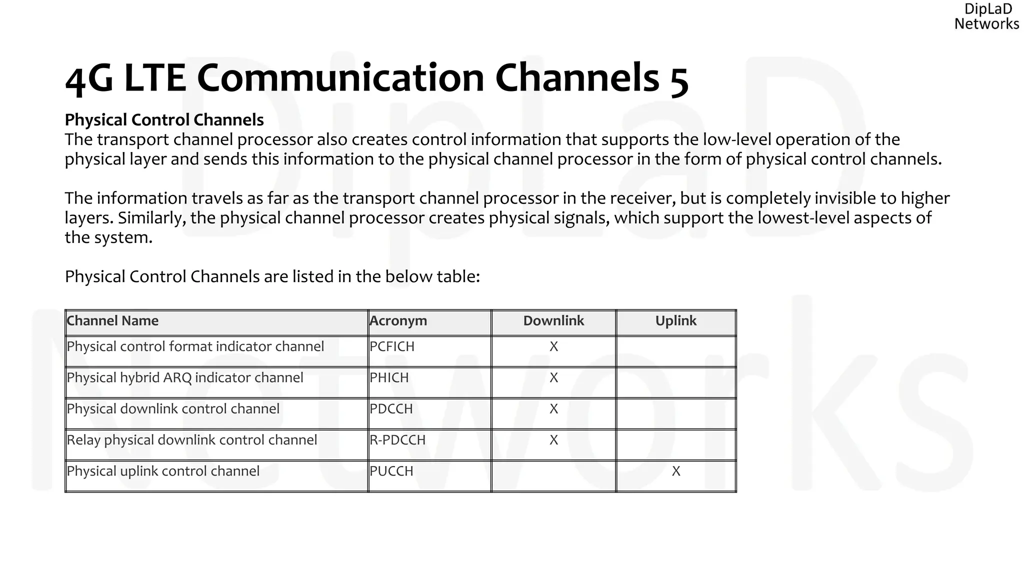
- A description of the different logical, transport, and physical channels used for communication in LTE networks
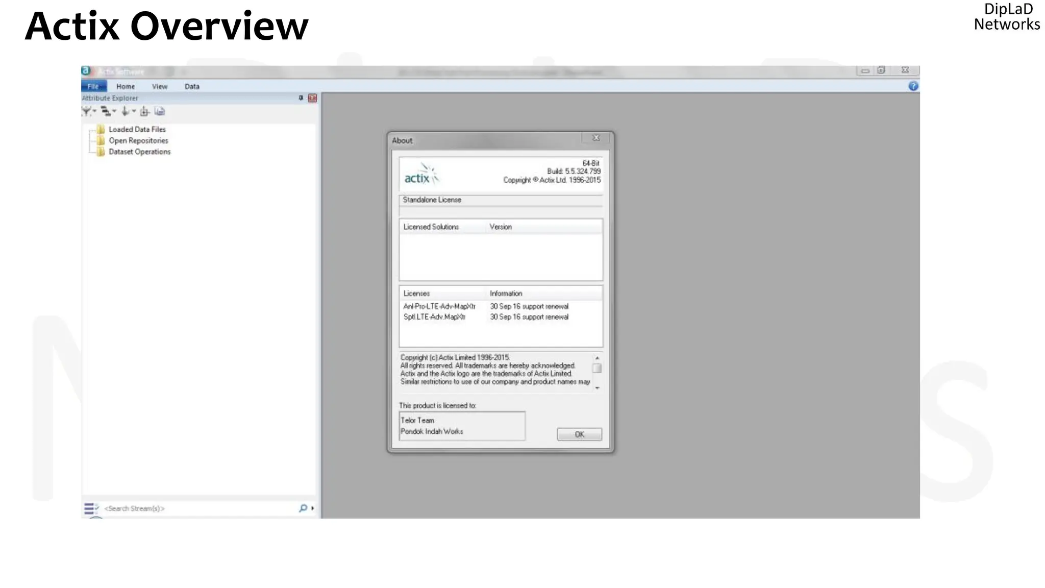
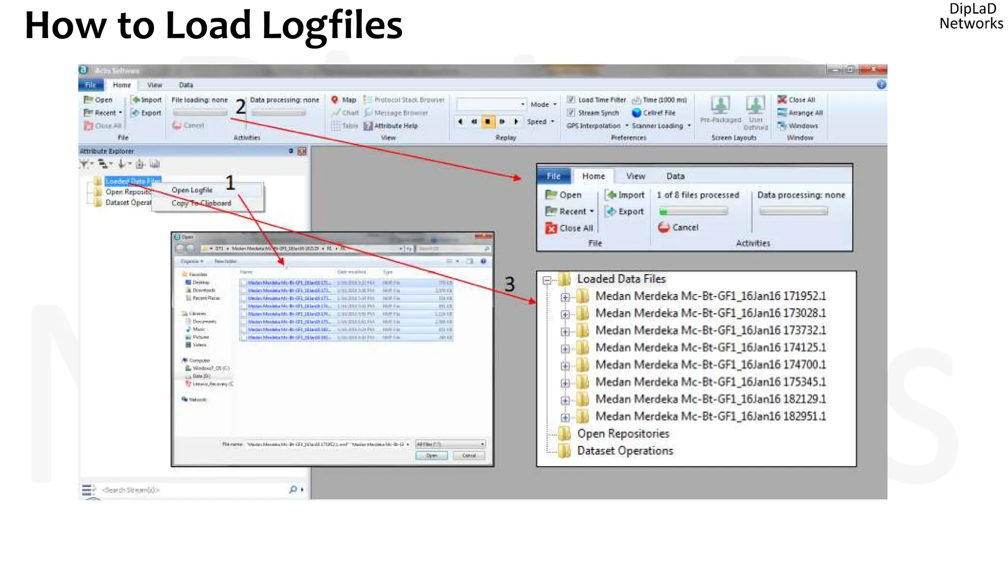
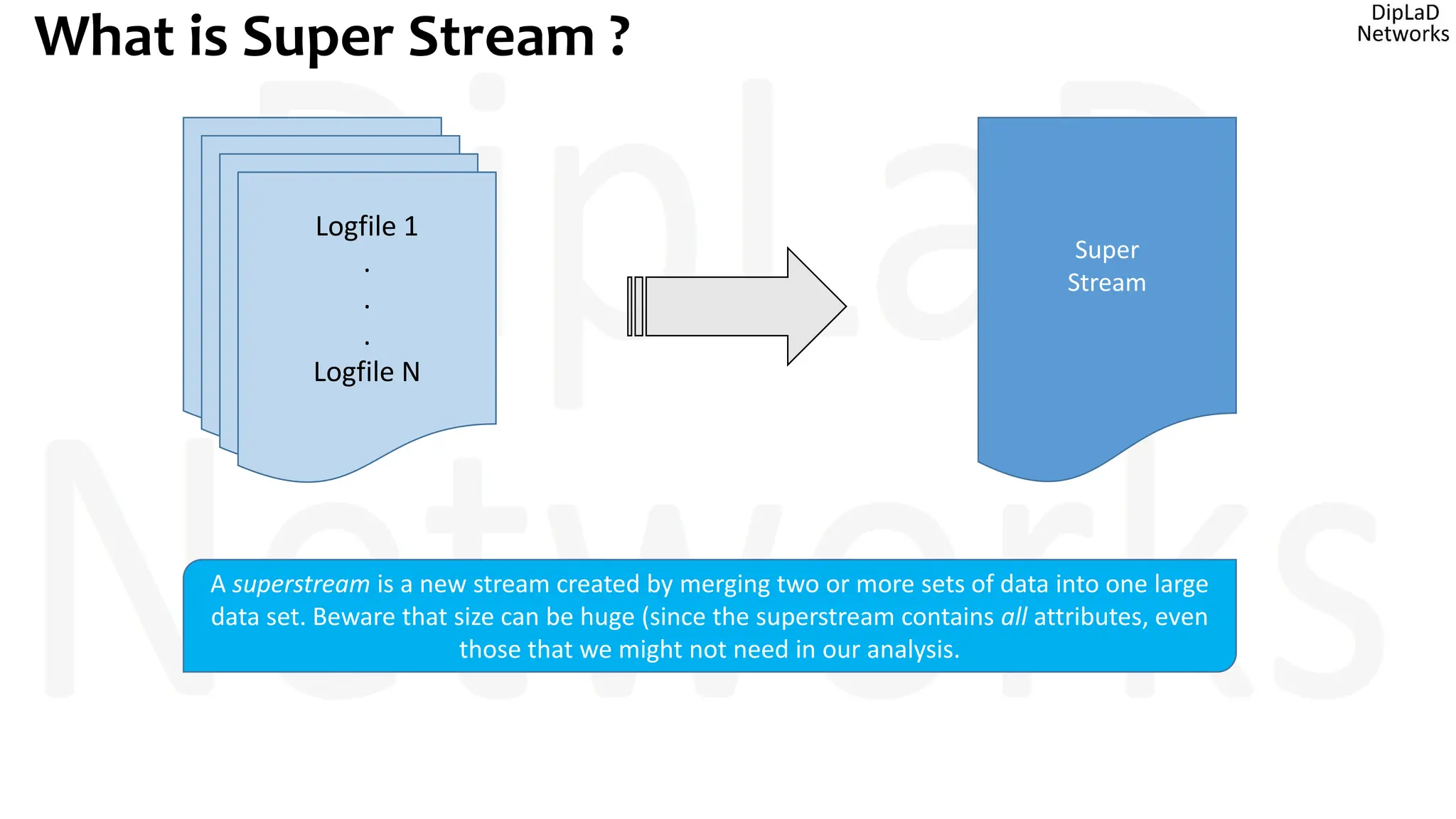
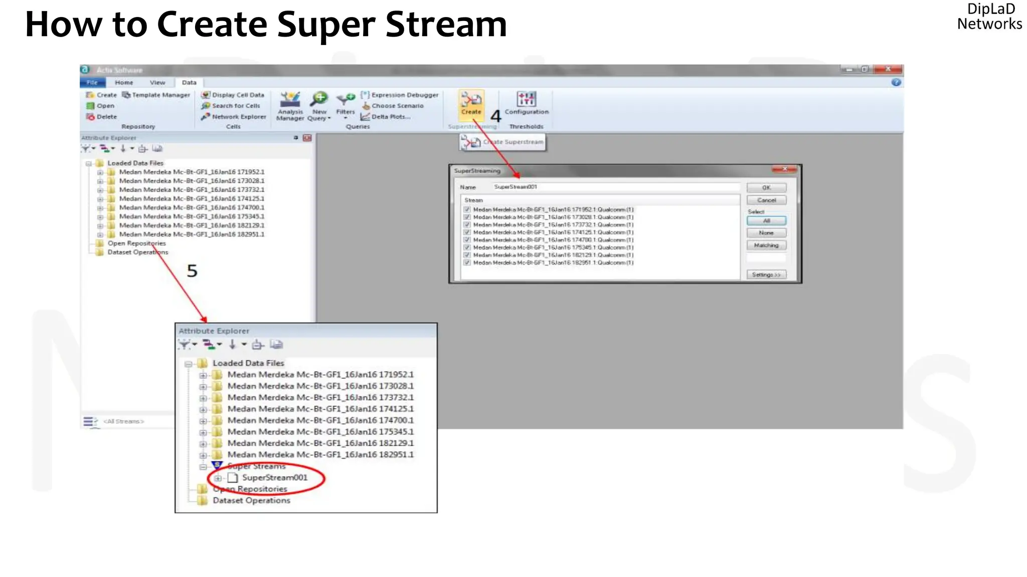
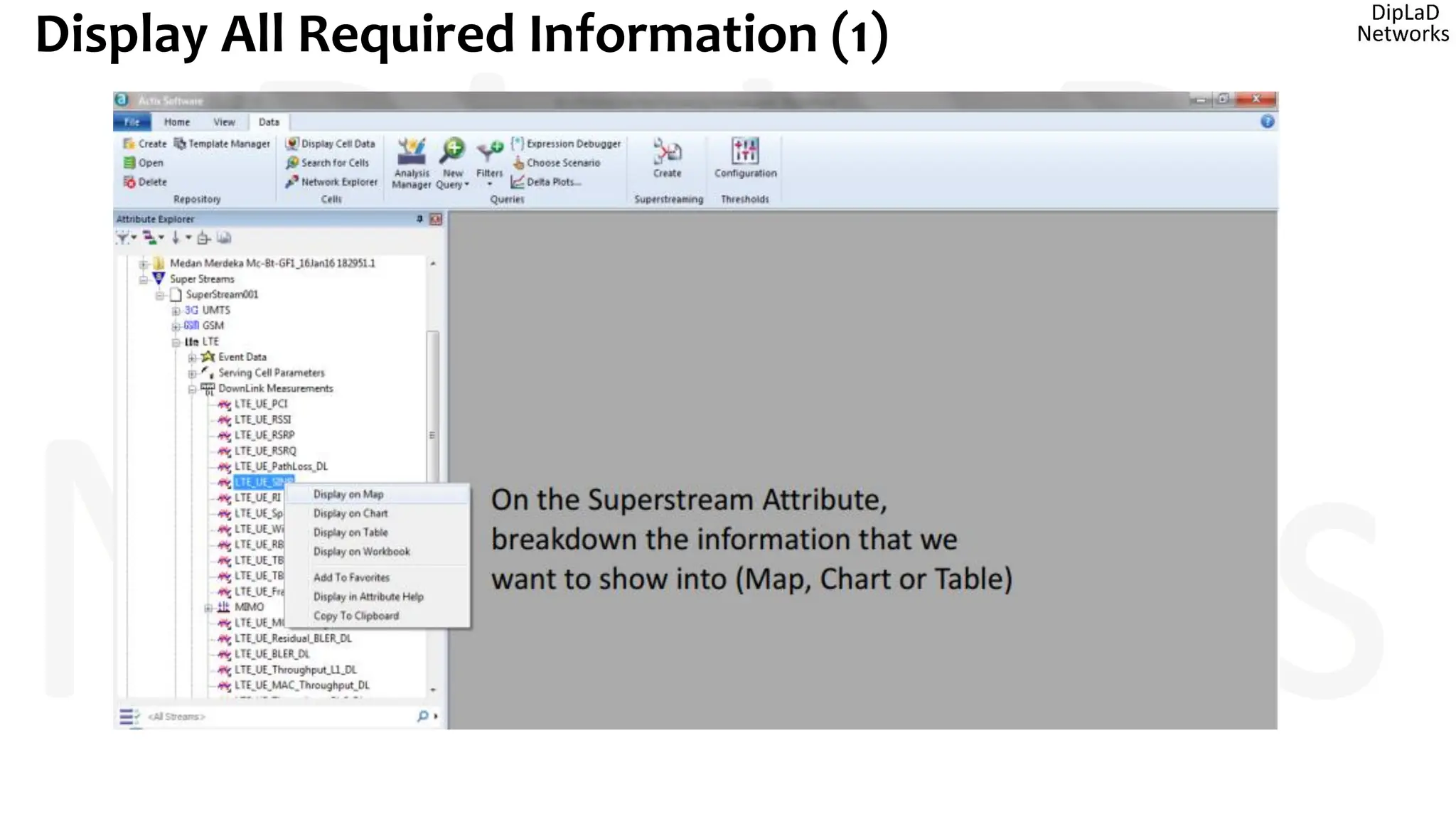
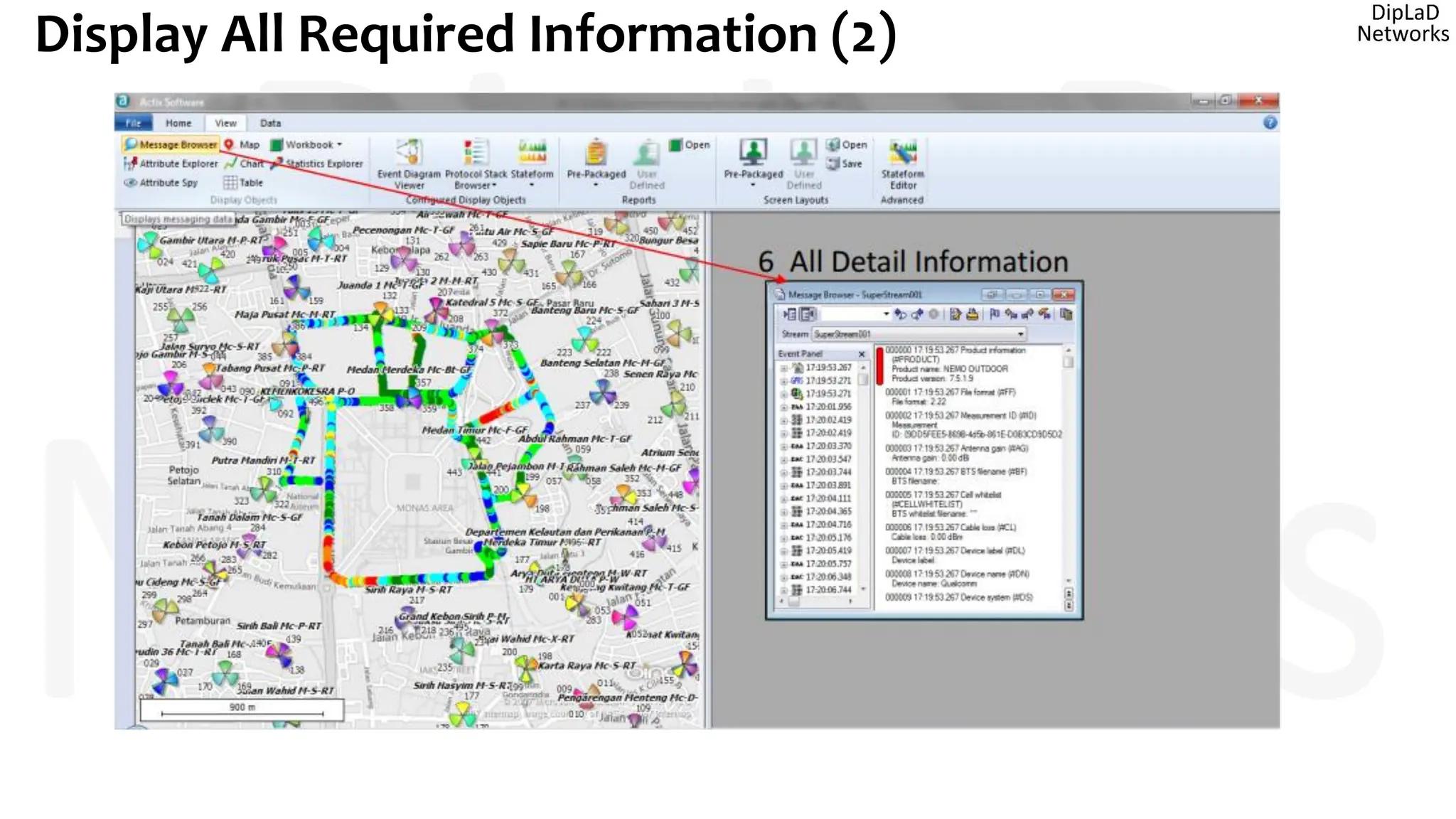
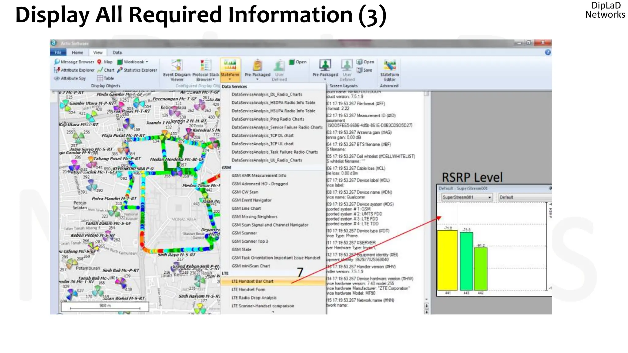
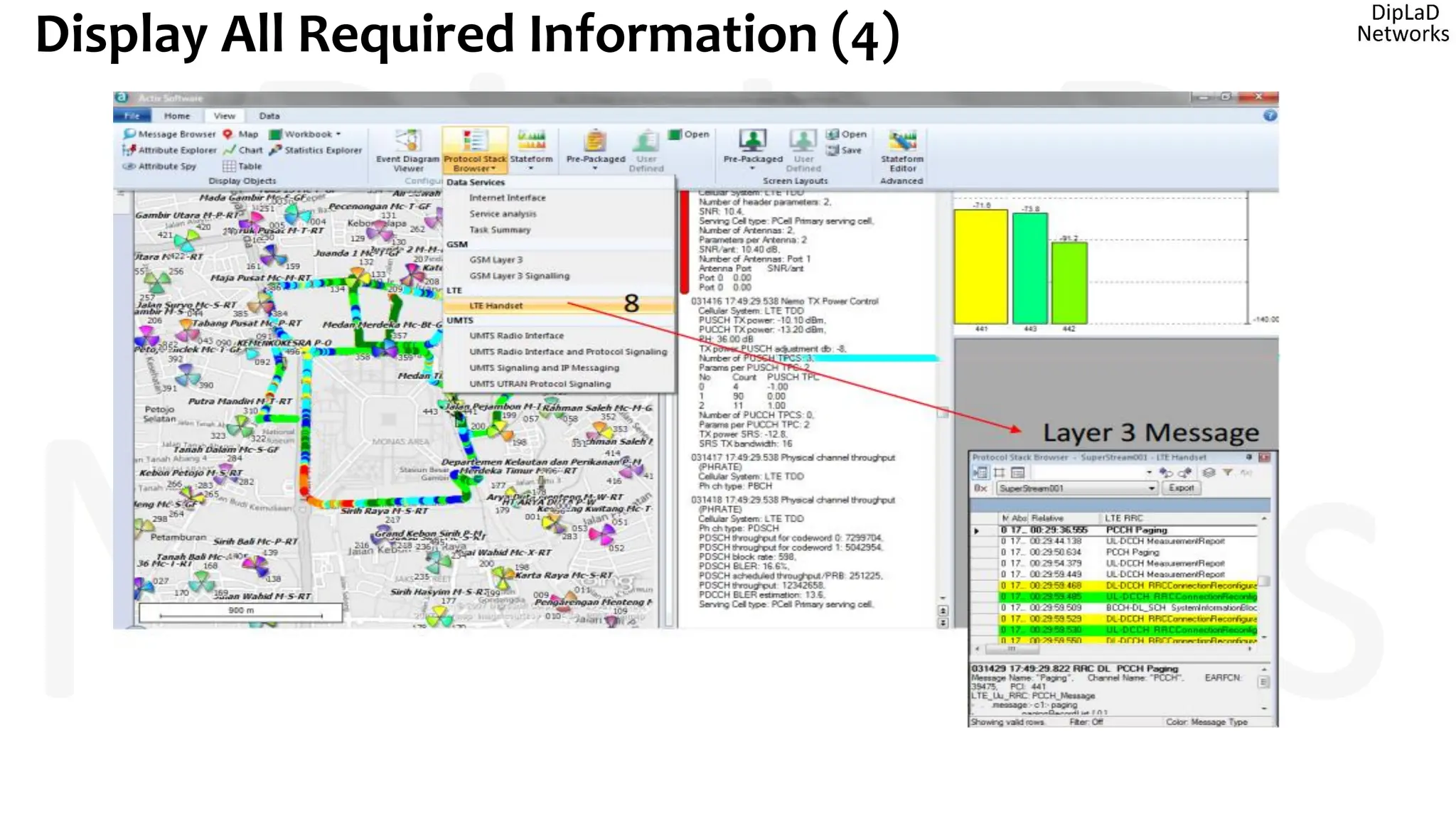
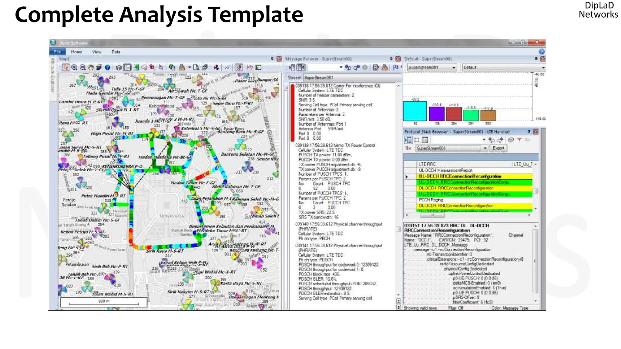
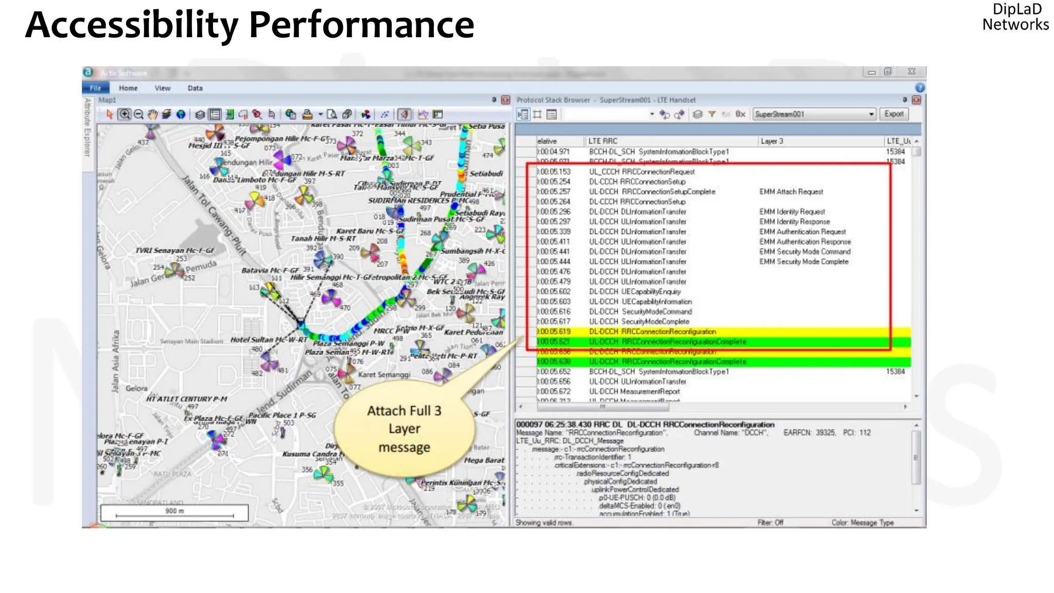
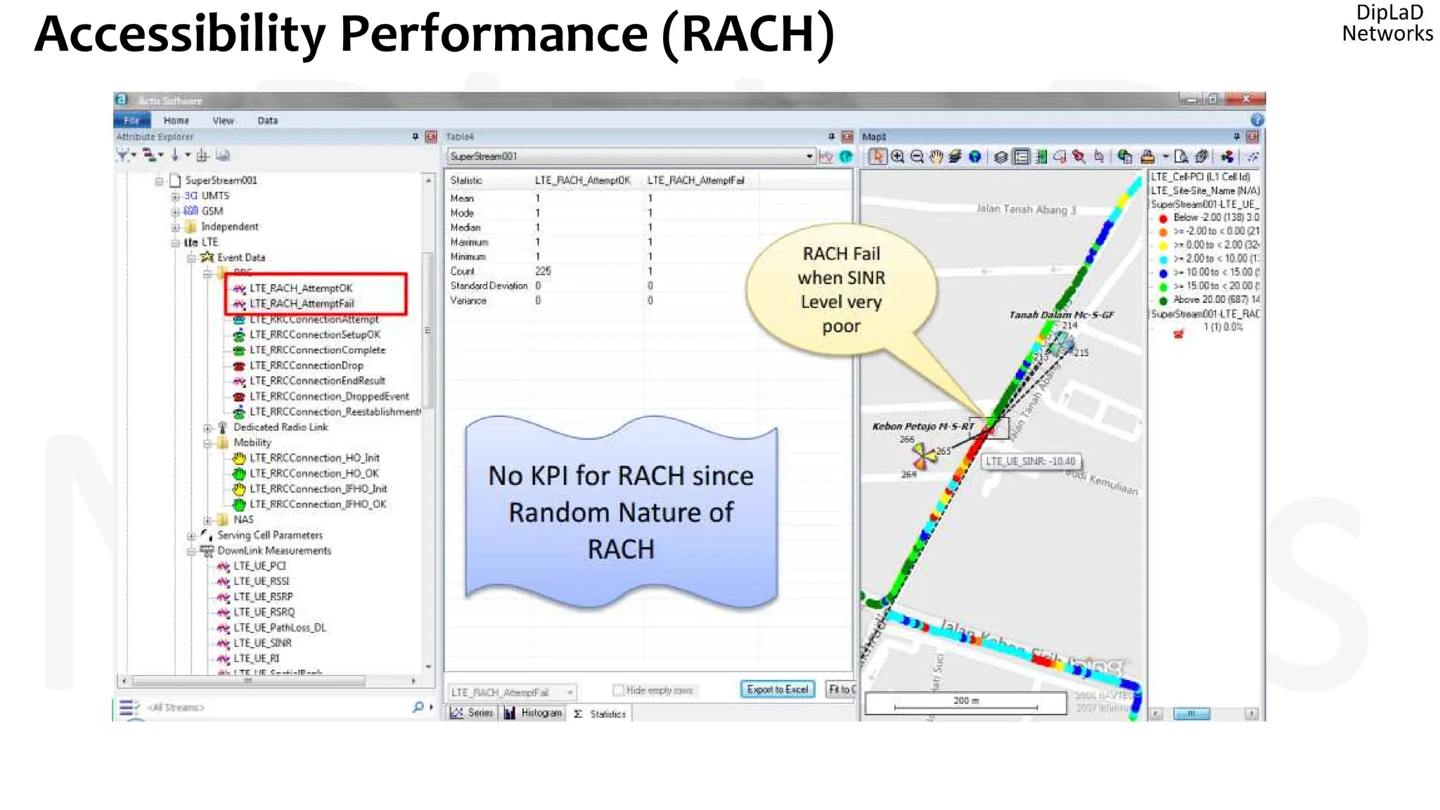
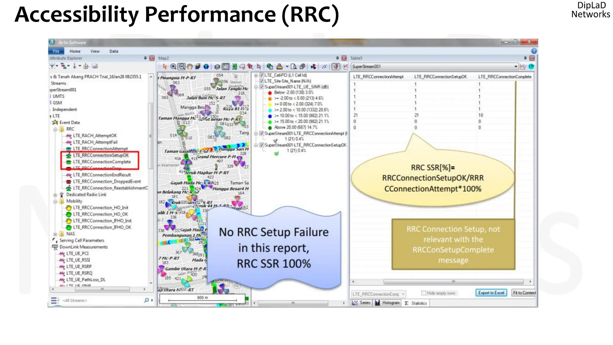
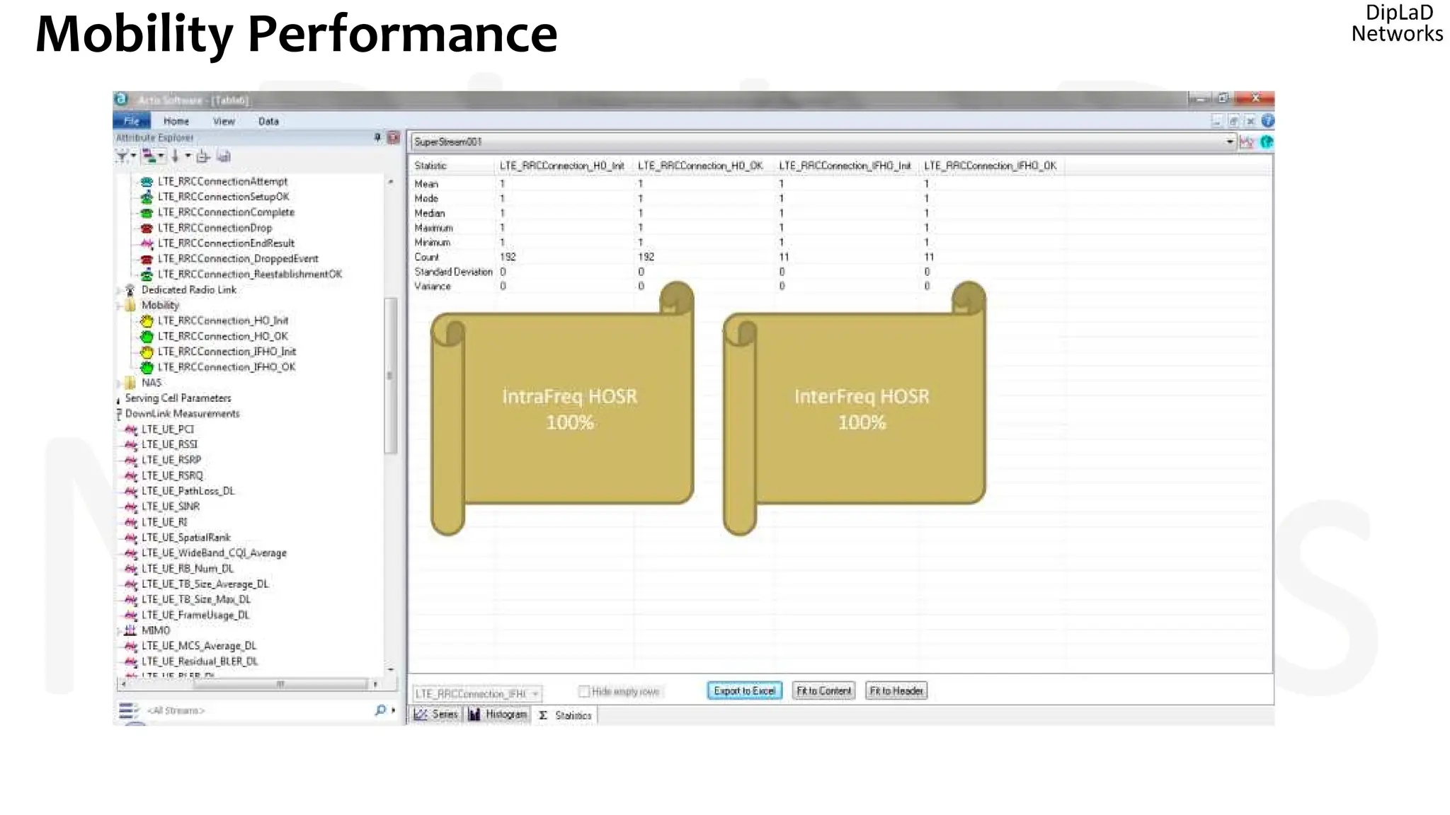
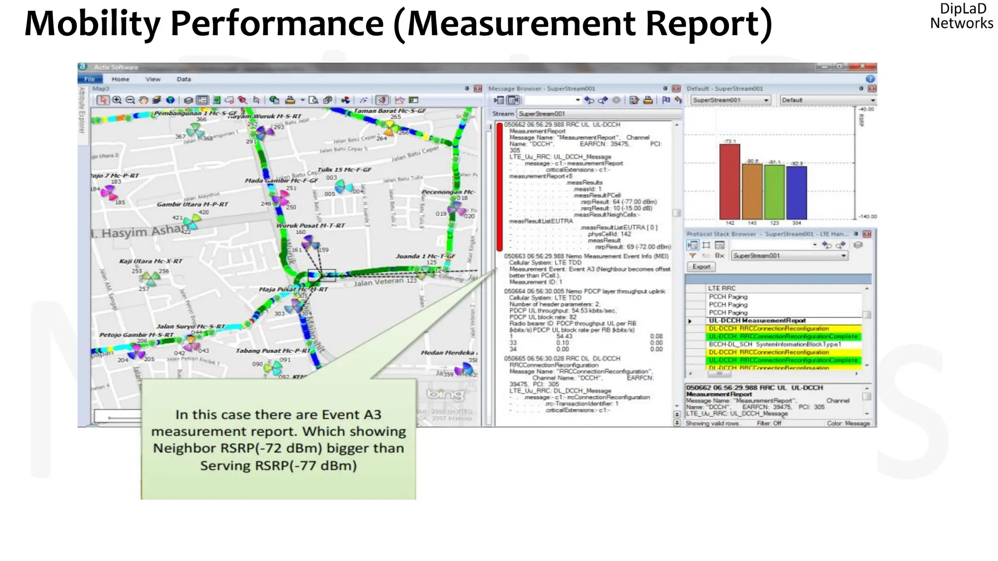
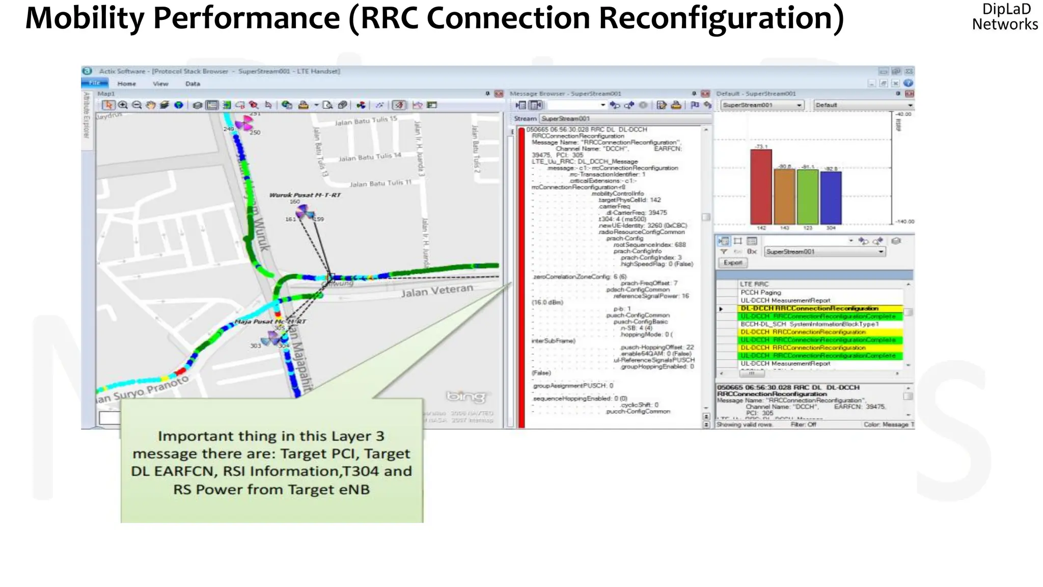
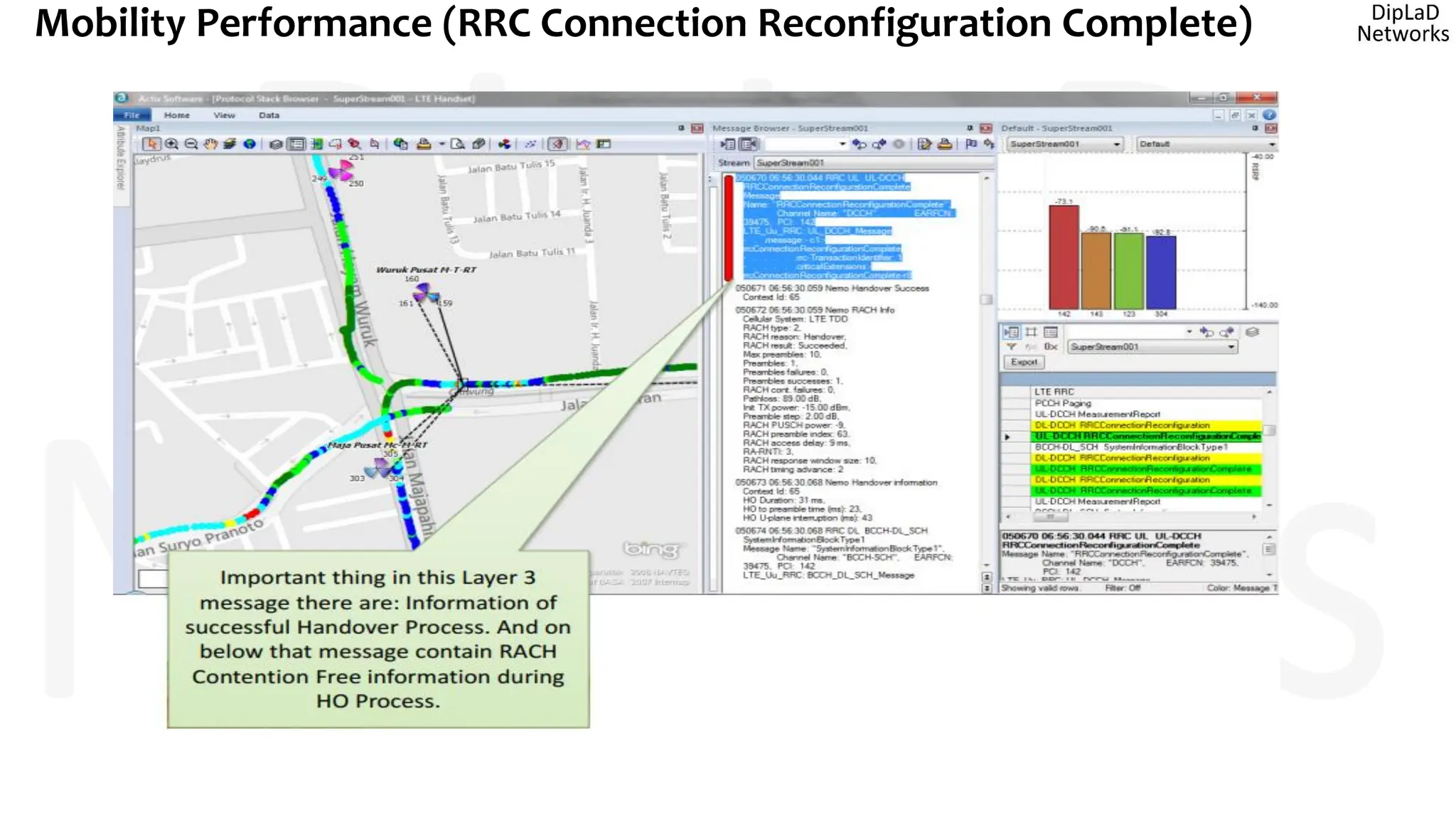
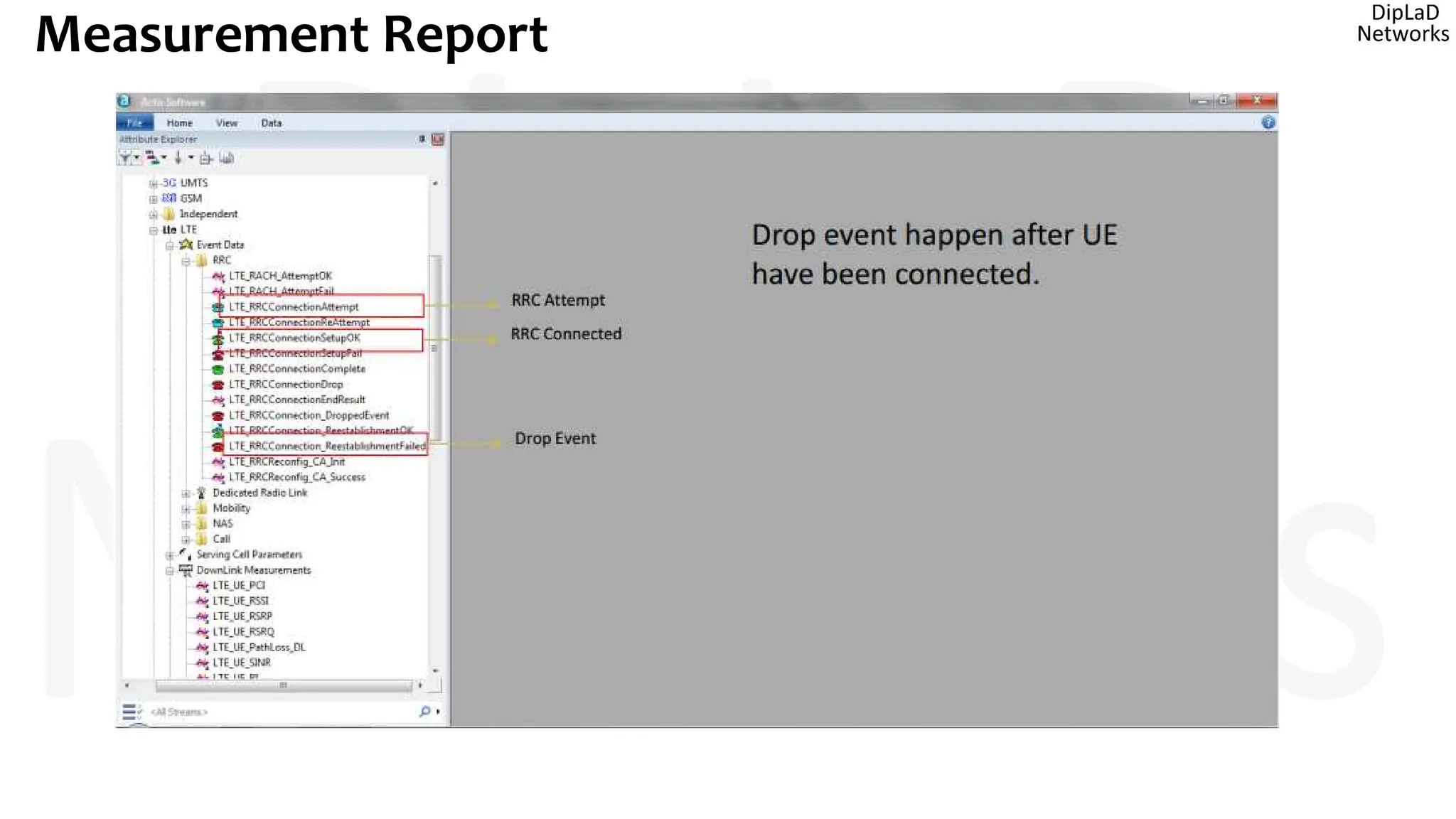
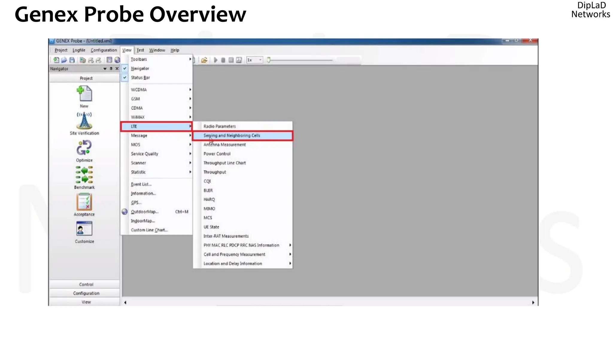
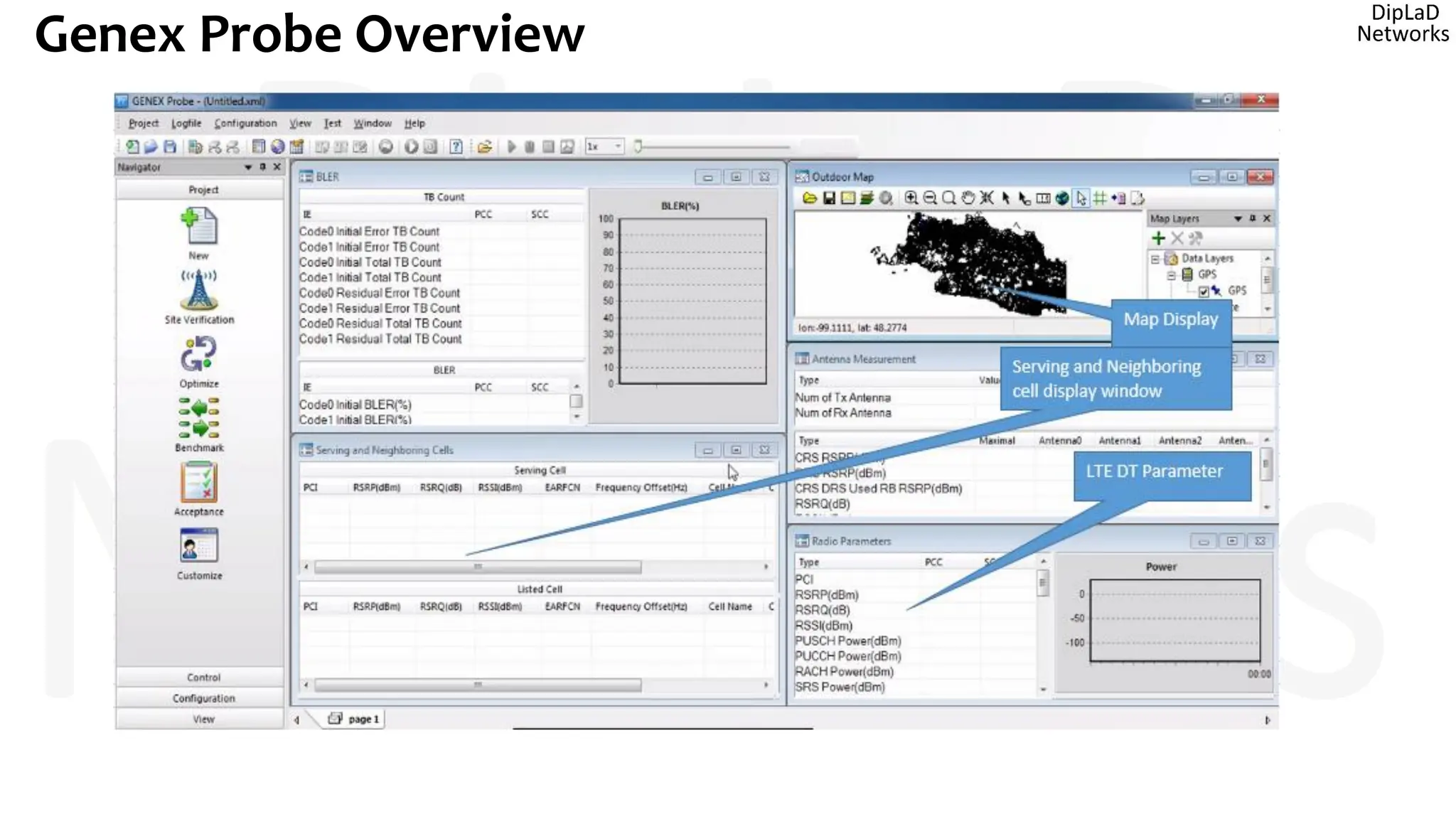
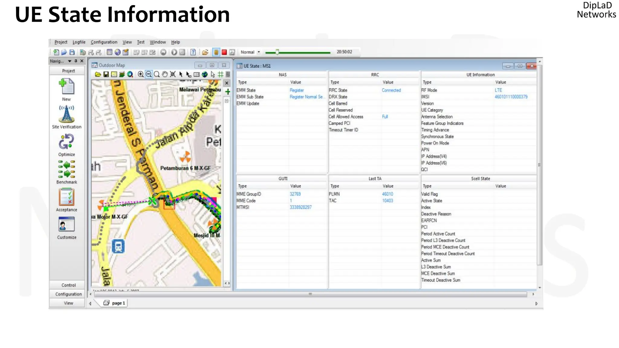
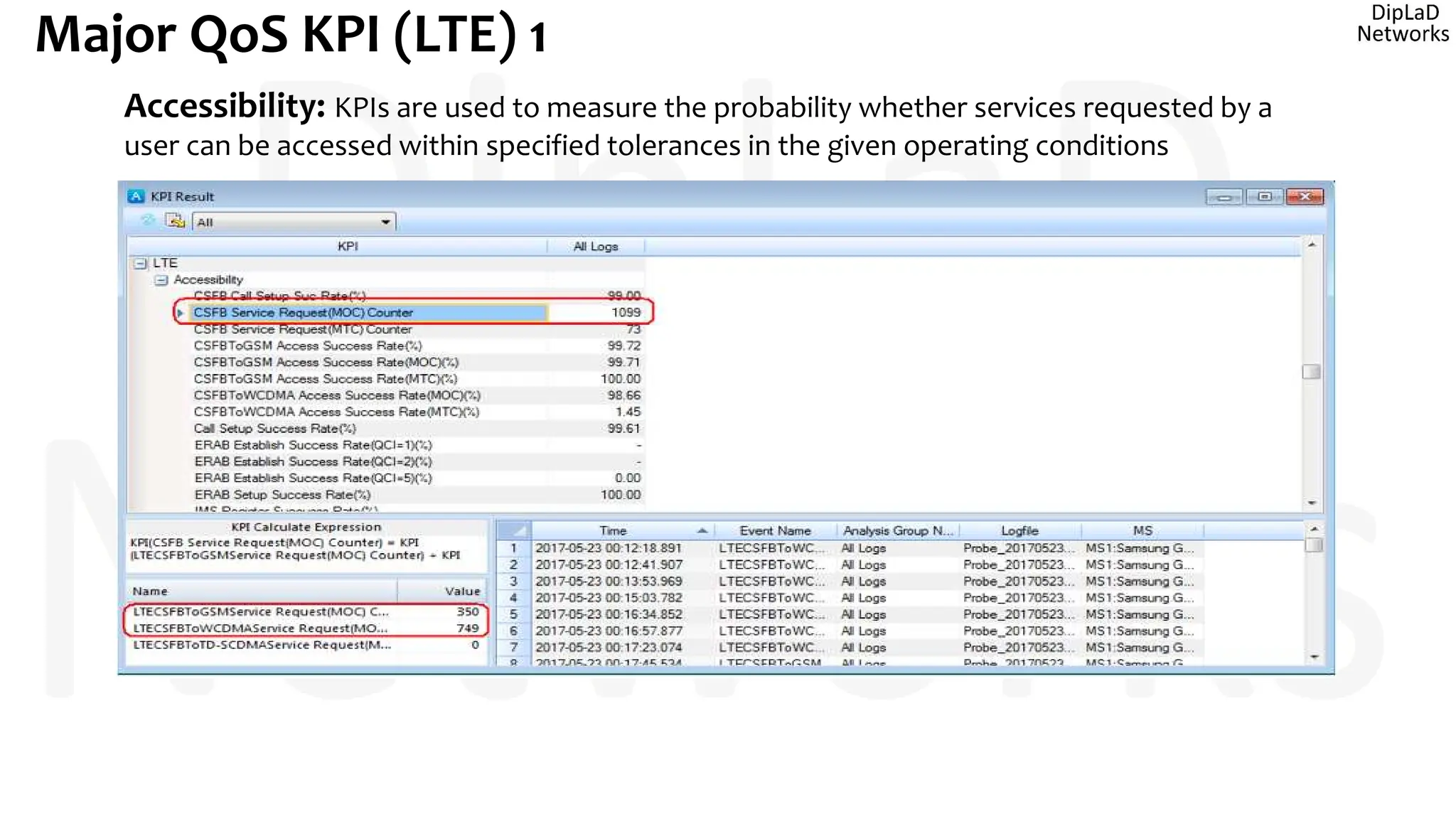
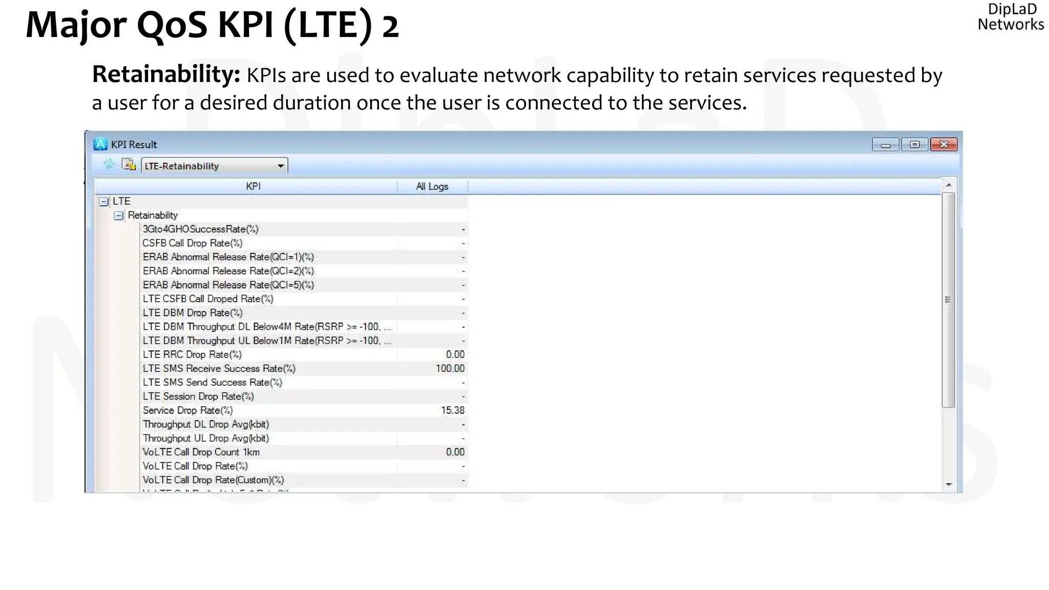
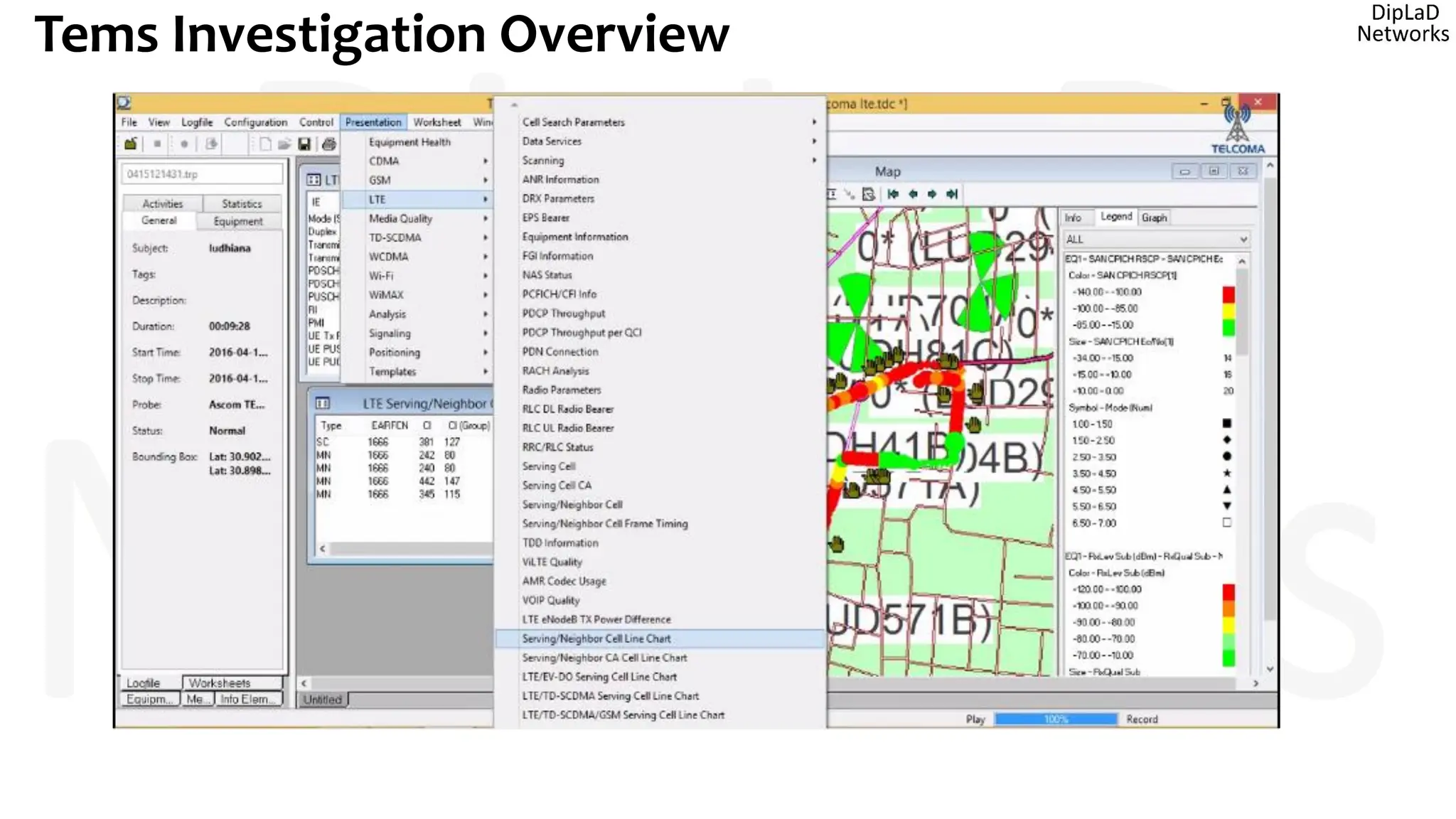
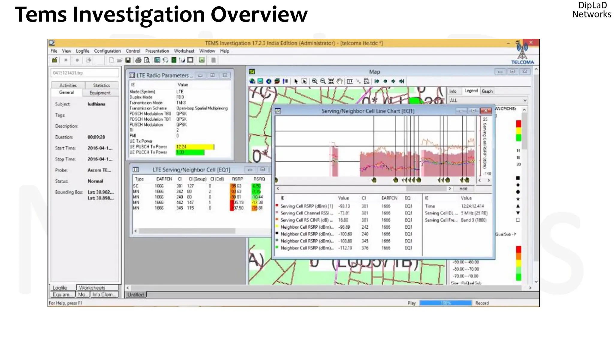
- A review of the post-processing of drive test logs and analysis using the Actix software


![Coded Agents – with UiPath SDK + LangGraph [Virtual Hands-on Workshop]](https://cdn.slidesharecdn.com/ss_thumbnails/codedagentsdeck-251215155422-5497c599-thumbnail.jpg?width=640&height=640&fit=bounds)


