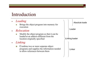
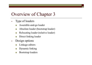
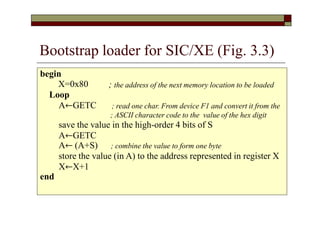
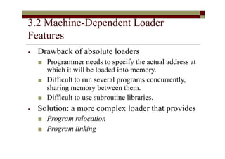
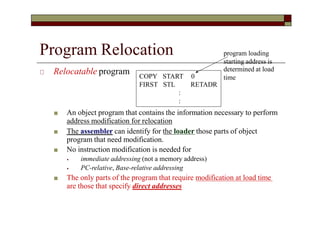
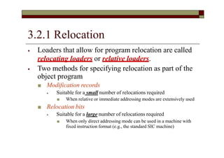
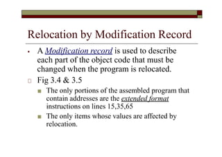
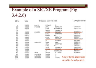
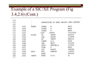
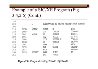
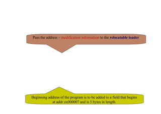
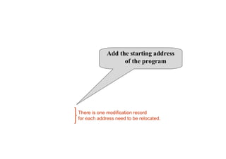
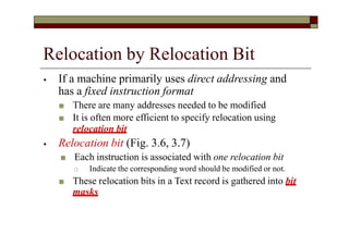
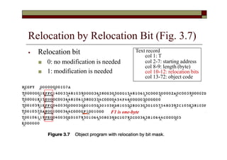
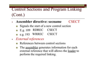
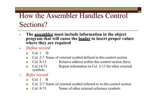
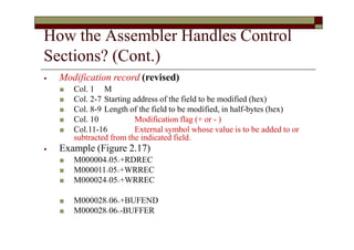
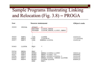
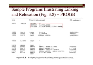
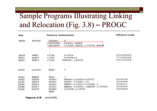
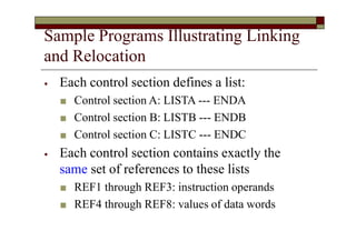
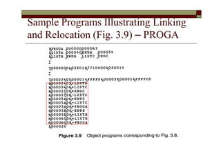
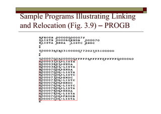
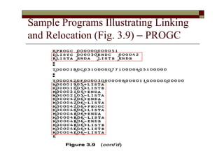
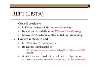
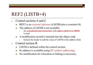
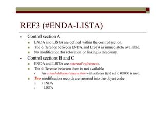
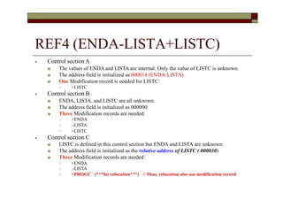
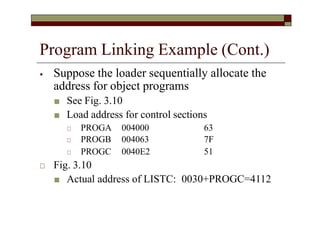
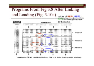
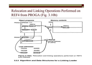
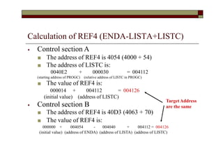
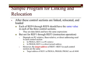
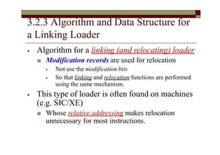
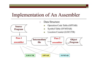
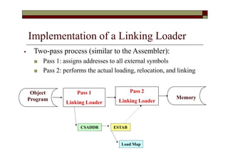
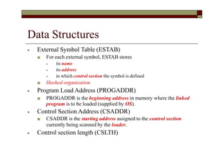
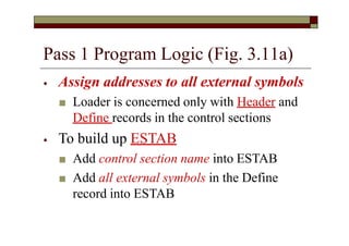
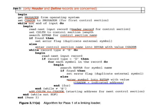
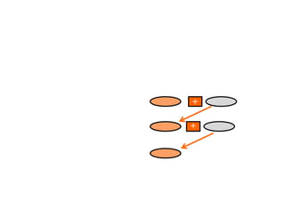
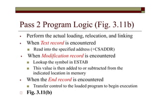
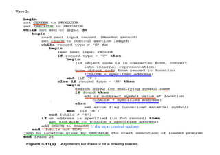
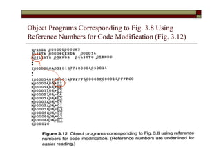
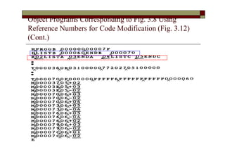
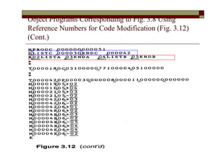
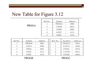
Chapter 3 Loaders and
Linkers
Outline
⦁ 3.1 Basic Loader Functions
⦁ 3.2 Machine-Dependent Loader Features
⦁ 3.3 Machine-Independent Loader Features
⦁ 3.4 Loader Design Options
⦁ 3.5 Implementation Examples
Introduction
⦁ Loading
■ Brings the object program into memory for
execution
⦁ Relocation
■ Modify the object program so that it can be
loaded at an address different from the
location originally specified
⦁ Linking
■ Combine two or more separate object
programs and supplies the information needed
to allow references between them
Absolute loade
Loader
Linking loader
Linker
Overview of Chapter 3
⦁ Type of loaders
■ Assemble-and-go loader
■ Absolute loader (bootstrap loader)
■ Relocating loader (relative loader)
■ Direct linking loader
⦁ Design options
■ Linkage editors
■ Dynamic linking
■ Bootstrap loaders
3.1 Basic Loader Functions
⦁ The most fundamental functions of a loader:
■ Bringing an object program into memory and
starting its execution
⦁ Design of an Assemble-and-Go Loader
⦁ Design of an Absolute Loader
⦁ A Simple Bootstrap Loader
3.1.0 Assemble-and-Go Loader
⦁ Characteristic
■ The object code is produced directly in memory for
immediate execution after assembly
⦁ Advantage
■ Useful for program development and testing
⦁ Disadvantage
■ Whenever the assembly program is to be executed, it has
to be assembled again
■ Programs consist of many control sections have to be
coded in the same language
3.1.1 Design of an Absolute Loader
⦁ Absolute Program (e.g. SIC programs)
■ Advantage
⦁ Simple and efficient
■ Disadvantages
⦁ The need for programmer to specify the actual address at which it
will be loaded into memory
⦁ Difficult to use subroutine libraries efficiently
⦁ Absolute loader only performs loading function
■ Does not need to perform linking and program relocation.
■ All functions are accomplished in a single pass.
Design of an Absolute Loader (Cont.)
⦁ In a single pass
■ Check the Header record for program name,
starting address, and length
■ Bring the object program contained in the Text
record to the indicated address
■ No need to perform program linking and
relocation
■ Start the execution by jumping to the address
specified in the End record
Loading of an Absolute Program (Fig
3.1 a)
⦁ Object program contains
■ H record
■ T record
■ E record
Loading of an Absolute Program (Fig
3.1 b)
Algorithm for an Absolute Loader (Fig. 3.2)
E.g., convert the pair of
characters “14” (two bytes) in
the object program to a single
byte with hexadecimal value 14
Object Code Representation
⦁ Figure 3.1 (a)
■ Each byte of assembled code is given using its
hexadecimal representation in character form
⦁ For example, 14 (opcode of STL) occupies two bytes of memory
⦁ Easy to read by human beings
■ Each pair of bytes from the object program record must be
packed together into one byte during loading.
⦁ Inefficient in terms of both space and execution time
⦁ Thus, most machine store object programs in a
binary form
3.1.2 A Simple Bootstrap Loader
⦁ Bootstrap Loader
■ When a computer is first turned on or restarted, a
special type of absolute loader, called a bootstrap
loader is executed
🞏 In PC, BIOS acts as a bootstrap loader
■ This bootstrap loads the first program to be run
by the computer -- usually an operating system
A Simple Bootstrap Loader (Cont.)
⦁ Example: a simple SIC/XE bootstrap loader (Fig. 3.3)
■ The bootstrap itself begins at address 0 in the memory of
the machine
■ It loads the OS (or some other program) starting address
0x80
⦁ The object code from device F1 is always loaded into
consecutive bytes of memory, starting at address 80.
■ After all the object code from device F1 has been loaded,
the bootstraps jumps to address 80
⦁ Begin the execution of the program that was loaded.
Bootstrap loader for SIC/XE (Fig. 3.3)
; the address of the next memory location to be loaded
begin
X=0x80
Loop
A←GETC ; read one char. From device F1 and convert it from the
; ASCII character code to the value of the hex digit
save the value in the high-order 4 bits of S
A←GETC
A← (A+S) ; combine the value to form one byte
store the value (in A) to the address represented in register X
X←X+1
end
3.2 Machine-Dependent Loader
Features
⦁ Drawback of absolute loaders
■ Programmer needs to specify the actual address at
which it will be loaded into memory.
■ Difficult to run several programs concurrently,
sharing memory between them.
■ Difficult to use subroutine libraries.
⦁ Solution: a more complex loader that provides
■ Program relocation
■ Program linking
Machine-Dependent Loader Features
(Cont.)
⦁ 3.2.1 Relocation
⦁ 3.2.2 Program Linking
⦁ 3.2.3 Algorithm and Data Structures
for a Linking Loader
Review
Section 2.2.2
Program Relocation
Program Relocation
🞏 Relocatable program
■ An object program that contains the information necessary to perform
address modification for relocation
■ The assembler can identify for the loader those parts of object
program that need modification.
■ No instruction modification is needed for
⦁ immediate addressing (not a memory address)
⦁ PC-relative, Base-relative addressing
■ The only parts of the program that require modification at load time
are those that specify direct addresses
COPY
FIRST
START 0
STL RETADR
:
:
program loading
starting address is
determined at load
time
Instruction Format vs. Relocatable
Loader
⦁ In SIC/XE
■ Relative and immediate addressing
⦁ Do not need to modify their object code after relocation
■ Extended format
⦁ Whose values are affected by relocation
⦁ Need to modify when relocation
⦁ In SIC
■ Format 3 with address field
⦁ Should be modified
⦁ SIC does not support PC-relative and base-relative addressing
3.2.1 Relocation
⦁ Loaders that allow for program relocation are called
relocating loaders or relative loaders.
⦁ Two methods for specifying relocation as part of the
object program
■ Modification records
⦁ Suitable for a small number of relocations required
■ When relative or immediate addressing modes are extensively used
■ Relocation bits
⦁ Suitable for a large number of relocations required
■ When only direct addressing mode can be used in a machine with
fixed instruction format (e.g., the standard SIC machine)
Relocation by Modification Record
⦁ A Modification record is used to describe
each part of the object code that must be
changed when the program is relocated.
🞏 Fig 3.4 & 3.5
■ The only portions of the assembled program that
contain addresses are the extended format
instructions on lines 15,35,65
■ The only items whose values are affected by
relocation.
Example of a SIC/XE Program (Fig
3.4,2.6)
Only three addresses
need to be relocated.
Example of a SIC/XE Program (Fig
3.4,2.6) (Cont.)
Example of a SIC/XE Program (Fig
3.4,2.6) (Cont.)
Relocatable Program
🞏 Modification record
■ Col 1 M
■ Col 2-7 Starting location of the address field to be
modified, relative to the beginning of the program (hex)
■ Col 8-9 length of the address field to be modified, in half-bytes
■ E.g M^000007^05
Pass the address – modification information to the relocatable loader
Beginning address of the program is to be added to a field that begins
at addr ox000007 and is 5 bytes in length.
Object Program with Relocation by
Modification Records for Fig 3.5 (Fig 2.8)
Add the starting address
of the program
There is one modification record
for each address need to be relocated.
Relocation by Modification Record
(Cont.)
⦁ The Modification record scheme is a
convenient means for specifying program
relocation.
⦁ However, it is not well suited for use with all
machine architectures
■ See Fig. 3.6.
⦁ Relocatable program for a SIC machine
■ Most instructions use direct addressing
⦁ Too many modification records
Relocatable program for a standard
SIC machine (Fig. 3.6)
Relocatable program for a standard
SIC machine (Fig. 3.6) (Cont.)
Relocatable program for a Standard
SIC Machine (fig. 3.6) (Cont.)
This SIC program does not use relative addressing.
The addresses in all the instructions except RSUB must be modified.
This would require 31 Modification records.
Relocation by Relocation Bit
⦁ If a machine primarily uses direct addressing and
has a fixed instruction format
■ There are many addresses needed to be modified
■ It is often more efficient to specify relocation using
relocation bit
⦁ Relocation bit (Fig. 3.6, 3.7)
■ Each instruction is associated with one relocation bit
🞏 Indicate the corresponding word should be modified or not.
■ These relocation bits in a Text record is gathered into bit
masks
Relocation by Relocation Bit (Fig. 3.7)
⦁ Relocation bit
■ 0: no modification is needed
■ 1: modification is needed
Text record
col 1: T
col 2-7: starting address
col 8-9: length (byte)
col 10-12: relocation bits
col 13-72: object code
F1 is one-byte
Relocation Bits (Cont.)
⦁ Each bit mask consists of 12 relocation bit in
each Text record
■ Since each text record contains less than 12 words
■ Unused words are set to 0
🞏 E.g. FFC=111111111100 for line 10-55
🞏 However, only 10 words in the first text record
Relocation Bits (Cont.)
⦁ Note that, any value that is to be modified
during relocation must coincide with one of
these 3-byte segments
■ E.g. Begin a new Text record for line 210
⦁ Because line 185 has only 1-byte object code (F1)
⦁ Make the following object code does not align to 3-
byte boundary
3.2.2 Program Linking
⦁ Control sections
■ Refer to segments of codes that are translated into
independent object program units
■ These control sections could be assembled
together or independently of one another
■ It is necessary to provide some means for linking
control sections together
⦁ External definitions
⦁ External references
Illustration of Control Sections and
Program Linking (Fig 2.15 & 2.16)
Illustration of Control Sections and
Program Linking (Fig 2.15 & 2.16) (Cont.)
Illustration of Control Sections and
Program Linking (Fig 2.15 & 2.16) (Cont.)
Control Sections and Program Linking
(Cont.)
⦁ Assembler directive: secname CSECT
■ Signals the start of a new control section
■ E.g. 109
■ e.g. 193
RDREC
WRREC
CSECT
CSECT
⦁ External references
■ References between control sections
■ The assembler generates information for each
external reference that will allows the loader to
perform the required linking.
How the Assembler Handles Control
Sections?
⦁ The assembler must include information in the object
program that will cause the loader to insert proper values
where they are required
⦁ Define record
■ Col. 1 D
■ Col. 2-7 Name of external symbol defined in this control section
Relative address within this control section (hex)
Repeat information in Col. 2-13 for other external
■ Col. 8-13
■ Col.14-73
symbols
🞏 Refer record
■ Col. 1 R
■ Col. 2-7 Name of external symbol referred to in this control section
■ Col. 8-73 Name of other external reference symbols
How the Assembler Handles Control
Sections? (Cont.)
⦁ Modification record (revised)
■ Col. 1 M
■ Col. 2-7 Starting address of the field to be modified (hex)
■ Col. 8-9 Length of the field to be modified, in half-bytes (hex)
■ Col. 10 Modification flag (+ or - )
■ Col.11-16 External symbol whose value is to be added to or
subtracted from the indicated field.
⦁ Example (Figure 2.17)
■ M000004^05^+RDREC
■ M000011^05^+WRREC
■ M000024^05^+WRREC
■ M000028^06^+BUFEND
■ M000028^06^-BUFFER
Program Linking (Cont.)
⦁ Goal of program linking
■ Resolve the problems with EXTREF and
EXTDEF from different control sections
⦁ Example:
■ Fig. 3.8 and Fig. 3.9
Sample Programs Illustrating Linking
and Relocation (Fig. 3.8) – PROGA
Sample Programs Illustrating Linking
and Relocation (Fig. 3.8) – PROGB
Sample Programs Illustrating Linking
and Relocation (Fig. 3.8) – PROGC
Sample Programs Illustrating Linking
and Relocation
⦁ Each control section defines a list:
■ Control section A: LISTA --- ENDA
■ Control section B: LISTB --- ENDB
■ Control section C: LISTC --- ENDC
⦁ Each control section contains exactly the
same set of references to these lists
■ REF1 through REF3: instruction operands
■ REF4 through REF8: values of data words
Sample Programs Illustrating Linking
and Relocation (Fig. 3.9) – PROGA
Sample Programs Illustrating Linking
and Relocation (Fig. 3.9) – PROGB
Sample Programs Illustrating Linking
and Relocation (Fig. 3.9) – PROGC
⦁ Control section A
■ LISTA is defined within the control section.
■ Its address is available using PC-relative addressing.
■ No modification for relocation or linking is necessary.
⦁ Control sections B and C
■ LISTA is an external reference.
■ Its address is not available
⦁ An extended-format instruction with address field set to 00000
is used.
■ A modification record is inserted into the object code
⦁ Instruct the loader to add the value of LISTA to this address field.
REF1 (LISTA)
REF2 (LISTB+4)
⦁ Control sections A and C
■ REF2 is an external reference (LISTB) plus a constant (4).
■ The address of LISTB is not available
⦁ An extended-format instruction with address field set to 00004
is used.
■ A modification record is inserted into the object code
⦁ Instruct the loader to add the value of LISTB to this address field.
⦁ Control section B
■ LISTB is defined within the control section.
■ Its address is available using PC-relative addressing.
■ No modification for relocation or linking is necessary.
REF3 (#ENDA-LISTA)
⦁ Control section A
■ ENDA and LISTA are defined within the control section.
■ The difference between ENDA and LISTA is immediately available.
■ No modification for relocation or linking is necessary.
⦁ Control sections B and C
■ ENDA and LISTA are external references.
■ The difference between them is not available
⦁ An extended-format instruction with address field set to 00000 is used.
■ Two modification records are inserted into the object code
🞏 +ENDA
⦁ -LISTA
REF4 (ENDA-LISTA+LISTC)
⦁ Control sectionA
■ The values of ENDA and LISTA are internal. Only the value of LISTC is unknown.
■ The address field is initialized as 000014 (ENDA-LISTA).
■ One Modification record is needed for LISTC:
🞏 +LISTC
⦁ Control section B
■ ENDA, LISTA, and LISTC are all unknown.
■ The address field is initialized as 000000.
■ Three Modification records are needed:
🞏
🞏
🞏
+ENDA
-LISTA
+LISTC
⦁ Control section C
■ LISTC is defined in this control section but ENDA and LISTA are unknown.
■ The address field is initialized as the relative address of LISTC ( 000030)
■ Three Modification records are needed:
🞏
🞏
🞏
+ENDA
-LISTA
+PROGC (***for relocation***) // Thus, relocation also use modification record
Program Linking Example (Cont.)
⦁ Suppose the loader sequentially allocate the
address for object programs
■ See Fig. 3.10
■ Load address for control sections
🞏 PROGA 004000 63
🞏 PROGB 004063 7F
🞏 PROGC 0040E2 51
🞏 Fig. 3.10
■ Actual address of LISTC: 0030+PROGC=4112
Programs From Fig 3.8 After Linking
and Loading (Fig. 3.10a) Values of REF4, REF5, …,
REF8 in three places are
all the same.
Relocation and Linking Operations Performed on
REF4 from PROGA (Fig. 3.10b)
Calculation of REF4 (ENDA-LISTA+LISTC)
⦁ Control section A
■ The address of REF4 is 4054 (4000 + 54)
■ The address of LISTC is:
0040E2 + 000030 = 004112
(starting address of PROGC) (relative address of LISTC in PROGC)
■ The value of REF4 is:
000014 + 004112 = 004126
(initial value) (address of LISTC)
⦁ Control section B
■ The address of REF4 is 40D3 (4063 + 70)
■ The value of REF4 is:
000000 + 004054 - 004040 + 004112 = 004126
(initial value) (address of ENDA) (address of LISTA) (address of LISTC)
TargetAddress
are the same
Sample Program for Linking and
Relocation
⦁ After these control sections are linked, relocated, and
loaded
■ Each of REF4 through REF8 should have the same value
in each of the three control sections.
⦁ They are data labels and have the same expressions
■ But not for REF1 through REF3 (instruction operation)
⦁ Depends on PC-relative, Base-relative, or direct addressing used
in each control section
■ In PROGA, REF1 is a PC-relative
■ In PROGB, REF1 is a direct (actual) address
⦁ However, the target address of REF1~REF3 in each control
section are the same
■ Target address of REF1 in PROGA, PROGB, PROGC are all 4040
3.2.3 Algorithm and Data Structure for
a Linking Loader
⦁ Algorithm for a linking (and relocating) loader
■ Modification records are used for relocation
⦁ Not use the modification bits
⦁ So that linking and relocation functions are performed
using the same mechanism.
⦁ This type of loader is often found on machines
(e.g. SIC/XE)
■ Whose relative addressing makes relocation
unnecessary for most instructions.
Implementation of An Assembler
Pass 1
assembler
Pass 2
assembler
Intermediate
file
OPTAB SYMTAB
LOCCTR
Source
Program
Object
Program
🞏 Data Structure
■ Operation Code Table (OPTAB)
■ Symbol Table (SYMTAB)
■ Location Counter (LOCCTR)
Implementation of a Linking Loader
Pass 1
Linking Loader
Pass 2
Linking Loader
ESTAB
Load Map
CSADDR
Object
Program Memory
⦁ Two-pass process (similar to the Assembler):
■ Pass 1: assigns addresses to all external symbols
■ Pass 2: performs the actual loading, relocation, and linking
Algorithm for a Linking Loader
⦁ Input is a set of object programs, i.e., control
sections
⦁ A linking loader usually makes two passes
over its input, just as an assembler does
■ Pass 1: assign addresses to all external symbols
■ Pass 2: perform the actual loading, relocation, and
linking
Data Structures
⦁ External Symbol Table (ESTAB)
■ For each external symbol, ESTAB stores
⦁ its name
⦁ its address
⦁ in which control section the symbol is defined
■ Hashed organization
⦁ Program Load Address (PROGADDR)
■ PROGADDR is the beginning address in memory where the linked
program is to be loaded (supplied by OS).
⦁ Control Section Address (CSADDR)
■ CSADDR is the starting address assigned to the control section
currently being scanned by the loader.
⦁ Control section length (CSLTH)
Pass 1 Program Logic (Fig. 3.11a)
⦁ Assign addresses to all external symbols
■ Loader is concerned only with Header and
Define records in the control sections
⦁ To build up ESTAB
■ Add control section name into ESTAB
■ Add all external symbols in the Define
record into ESTAB
(only Header and Define records are concerned)
Load Map
🞏 ESTAB (External Symbol Table) may also look like Load MAP
+
+
Pass 2 Program Logic (Fig. 3.11b)
⦁ Perform the actual loading, relocation, and linking
⦁ When Text record is encountered
■ Read into the specified address (+CSADDR)
⦁ When Modification record is encountered
■ Lookup the symbol in ESTAB
■ This value is then added to or subtracted from the
indicated location in memory
⦁ When the End record is encountered
■ Transfer control to the loaded program to begin execution
🞏 Fig. 3.11(b)
// the next control section
Improve Efficiency
⦁ Use local searching instead of multiple searches of ESTAB
for the same symbol
■ Assign a reference number to each external symbol referred to in a
control section
■ The reference number (instead of symbol name) is also used in
Modification records
⦁ Avoiding multiple searches of ESTAB for the same symbol
during the loading of a control section.
■ Search of ESTAB for each external symbol can be performed once
and the result is stored in a new table indexed by the reference
number.
■ The values for code modification can then be obtained by simply
indexing into the table.
Improve Efficiency (Cont.)
⦁ Implementation
■ 01: control section name
■ other: external reference symbols
⦁ Example
■ Fig. 3.12
Object Programs Corresponding to Fig. 3.8 Using
Reference Numbers for Code Modification (Fig. 3.12)
Object Programs Corresponding to Fig. 3.8 Using
Reference Numbers for Code Modification (Fig. 3.12)
(Cont.)
Object Programs Corresponding to Fig. 3.8 Using
Reference Numbers for Code Modification (Fig. 3.12)
(Cont.)
New Table for Figure 3.12
Ref No. Symbol Address
1 PROGA 4000
2 LISTB 40C3
3 ENDB 40D3
4 LISTC 4112
5 ENDC 4124
Ref No. Symbol Address
1 PROGB 4063
2 LISTA 4040
3 ENDA 4054
4 LISTC 4112
5 ENDC 4124
R e f N o . S y m b o l A d d r e s s
1 P R O G C 4 0 6 3
2 L I S T A 4 0 4 0
3 E N D A 4 0 5 4
4 L I S T B 4 0 C 3
5 E N D B 4 0 D 3
PROGA
PROGB PROGC

Loader and linker.pptx

  • 1.
    Chapter 3 Loadersand Linkers
  • 2.
    Outline ⦁ 3.1 BasicLoader Functions ⦁ 3.2 Machine-Dependent Loader Features ⦁ 3.3 Machine-Independent Loader Features ⦁ 3.4 Loader Design Options ⦁ 3.5 Implementation Examples
  • 3.
    Introduction ⦁ Loading ■ Bringsthe object program into memory for execution ⦁ Relocation ■ Modify the object program so that it can be loaded at an address different from the location originally specified ⦁ Linking ■ Combine two or more separate object programs and supplies the information needed to allow references between them Absolute loade Loader Linking loader Linker
  • 4.
    Overview of Chapter3 ⦁ Type of loaders ■ Assemble-and-go loader ■ Absolute loader (bootstrap loader) ■ Relocating loader (relative loader) ■ Direct linking loader ⦁ Design options ■ Linkage editors ■ Dynamic linking ■ Bootstrap loaders
  • 5.
    3.1 Basic LoaderFunctions ⦁ The most fundamental functions of a loader: ■ Bringing an object program into memory and starting its execution ⦁ Design of an Assemble-and-Go Loader ⦁ Design of an Absolute Loader ⦁ A Simple Bootstrap Loader
  • 6.
    3.1.0 Assemble-and-Go Loader ⦁Characteristic ■ The object code is produced directly in memory for immediate execution after assembly ⦁ Advantage ■ Useful for program development and testing ⦁ Disadvantage ■ Whenever the assembly program is to be executed, it has to be assembled again ■ Programs consist of many control sections have to be coded in the same language
  • 7.
    3.1.1 Design ofan Absolute Loader ⦁ Absolute Program (e.g. SIC programs) ■ Advantage ⦁ Simple and efficient ■ Disadvantages ⦁ The need for programmer to specify the actual address at which it will be loaded into memory ⦁ Difficult to use subroutine libraries efficiently ⦁ Absolute loader only performs loading function ■ Does not need to perform linking and program relocation. ■ All functions are accomplished in a single pass.
  • 8.
    Design of anAbsolute Loader (Cont.) ⦁ In a single pass ■ Check the Header record for program name, starting address, and length ■ Bring the object program contained in the Text record to the indicated address ■ No need to perform program linking and relocation ■ Start the execution by jumping to the address specified in the End record
  • 9.
    Loading of anAbsolute Program (Fig 3.1 a) ⦁ Object program contains ■ H record ■ T record ■ E record
  • 10.
    Loading of anAbsolute Program (Fig 3.1 b)
  • 11.
    Algorithm for anAbsolute Loader (Fig. 3.2) E.g., convert the pair of characters “14” (two bytes) in the object program to a single byte with hexadecimal value 14
  • 12.
    Object Code Representation ⦁Figure 3.1 (a) ■ Each byte of assembled code is given using its hexadecimal representation in character form ⦁ For example, 14 (opcode of STL) occupies two bytes of memory ⦁ Easy to read by human beings ■ Each pair of bytes from the object program record must be packed together into one byte during loading. ⦁ Inefficient in terms of both space and execution time ⦁ Thus, most machine store object programs in a binary form
  • 13.
    3.1.2 A SimpleBootstrap Loader ⦁ Bootstrap Loader ■ When a computer is first turned on or restarted, a special type of absolute loader, called a bootstrap loader is executed 🞏 In PC, BIOS acts as a bootstrap loader ■ This bootstrap loads the first program to be run by the computer -- usually an operating system
  • 14.
    A Simple BootstrapLoader (Cont.) ⦁ Example: a simple SIC/XE bootstrap loader (Fig. 3.3) ■ The bootstrap itself begins at address 0 in the memory of the machine ■ It loads the OS (or some other program) starting address 0x80 ⦁ The object code from device F1 is always loaded into consecutive bytes of memory, starting at address 80. ■ After all the object code from device F1 has been loaded, the bootstraps jumps to address 80 ⦁ Begin the execution of the program that was loaded.
  • 15.
    Bootstrap loader forSIC/XE (Fig. 3.3)
  • 16.
    Bootstrap loader forSIC/XE (Fig. 3.3)
  • 17.
    Bootstrap loader forSIC/XE (Fig. 3.3) ; the address of the next memory location to be loaded begin X=0x80 Loop A←GETC ; read one char. From device F1 and convert it from the ; ASCII character code to the value of the hex digit save the value in the high-order 4 bits of S A←GETC A← (A+S) ; combine the value to form one byte store the value (in A) to the address represented in register X X←X+1 end
  • 18.
    3.2 Machine-Dependent Loader Features ⦁Drawback of absolute loaders ■ Programmer needs to specify the actual address at which it will be loaded into memory. ■ Difficult to run several programs concurrently, sharing memory between them. ■ Difficult to use subroutine libraries. ⦁ Solution: a more complex loader that provides ■ Program relocation ■ Program linking
  • 19.
    Machine-Dependent Loader Features (Cont.) ⦁3.2.1 Relocation ⦁ 3.2.2 Program Linking ⦁ 3.2.3 Algorithm and Data Structures for a Linking Loader
  • 20.
  • 21.
    Program Relocation 🞏 Relocatableprogram ■ An object program that contains the information necessary to perform address modification for relocation ■ The assembler can identify for the loader those parts of object program that need modification. ■ No instruction modification is needed for ⦁ immediate addressing (not a memory address) ⦁ PC-relative, Base-relative addressing ■ The only parts of the program that require modification at load time are those that specify direct addresses COPY FIRST START 0 STL RETADR : : program loading starting address is determined at load time
  • 22.
    Instruction Format vs.Relocatable Loader ⦁ In SIC/XE ■ Relative and immediate addressing ⦁ Do not need to modify their object code after relocation ■ Extended format ⦁ Whose values are affected by relocation ⦁ Need to modify when relocation ⦁ In SIC ■ Format 3 with address field ⦁ Should be modified ⦁ SIC does not support PC-relative and base-relative addressing
  • 23.
    3.2.1 Relocation ⦁ Loadersthat allow for program relocation are called relocating loaders or relative loaders. ⦁ Two methods for specifying relocation as part of the object program ■ Modification records ⦁ Suitable for a small number of relocations required ■ When relative or immediate addressing modes are extensively used ■ Relocation bits ⦁ Suitable for a large number of relocations required ■ When only direct addressing mode can be used in a machine with fixed instruction format (e.g., the standard SIC machine)
  • 24.
    Relocation by ModificationRecord ⦁ A Modification record is used to describe each part of the object code that must be changed when the program is relocated. 🞏 Fig 3.4 & 3.5 ■ The only portions of the assembled program that contain addresses are the extended format instructions on lines 15,35,65 ■ The only items whose values are affected by relocation.
  • 25.
    Example of aSIC/XE Program (Fig 3.4,2.6) Only three addresses need to be relocated.
  • 26.
    Example of aSIC/XE Program (Fig 3.4,2.6) (Cont.)
  • 27.
    Example of aSIC/XE Program (Fig 3.4,2.6) (Cont.)
  • 28.
    Relocatable Program 🞏 Modificationrecord ■ Col 1 M ■ Col 2-7 Starting location of the address field to be modified, relative to the beginning of the program (hex) ■ Col 8-9 length of the address field to be modified, in half-bytes ■ E.g M^000007^05 Pass the address – modification information to the relocatable loader Beginning address of the program is to be added to a field that begins at addr ox000007 and is 5 bytes in length.
  • 29.
    Object Program withRelocation by Modification Records for Fig 3.5 (Fig 2.8) Add the starting address of the program There is one modification record for each address need to be relocated.
  • 30.
    Relocation by ModificationRecord (Cont.) ⦁ The Modification record scheme is a convenient means for specifying program relocation. ⦁ However, it is not well suited for use with all machine architectures ■ See Fig. 3.6. ⦁ Relocatable program for a SIC machine ■ Most instructions use direct addressing ⦁ Too many modification records
  • 31.
    Relocatable program fora standard SIC machine (Fig. 3.6)
  • 32.
    Relocatable program fora standard SIC machine (Fig. 3.6) (Cont.)
  • 33.
    Relocatable program fora Standard SIC Machine (fig. 3.6) (Cont.) This SIC program does not use relative addressing. The addresses in all the instructions except RSUB must be modified. This would require 31 Modification records.
  • 34.
    Relocation by RelocationBit ⦁ If a machine primarily uses direct addressing and has a fixed instruction format ■ There are many addresses needed to be modified ■ It is often more efficient to specify relocation using relocation bit ⦁ Relocation bit (Fig. 3.6, 3.7) ■ Each instruction is associated with one relocation bit 🞏 Indicate the corresponding word should be modified or not. ■ These relocation bits in a Text record is gathered into bit masks
  • 35.
    Relocation by RelocationBit (Fig. 3.7) ⦁ Relocation bit ■ 0: no modification is needed ■ 1: modification is needed Text record col 1: T col 2-7: starting address col 8-9: length (byte) col 10-12: relocation bits col 13-72: object code F1 is one-byte
  • 36.
    Relocation Bits (Cont.) ⦁Each bit mask consists of 12 relocation bit in each Text record ■ Since each text record contains less than 12 words ■ Unused words are set to 0 🞏 E.g. FFC=111111111100 for line 10-55 🞏 However, only 10 words in the first text record
  • 37.
    Relocation Bits (Cont.) ⦁Note that, any value that is to be modified during relocation must coincide with one of these 3-byte segments ■ E.g. Begin a new Text record for line 210 ⦁ Because line 185 has only 1-byte object code (F1) ⦁ Make the following object code does not align to 3- byte boundary
  • 38.
    3.2.2 Program Linking ⦁Control sections ■ Refer to segments of codes that are translated into independent object program units ■ These control sections could be assembled together or independently of one another ■ It is necessary to provide some means for linking control sections together ⦁ External definitions ⦁ External references
  • 39.
    Illustration of ControlSections and Program Linking (Fig 2.15 & 2.16)
  • 40.
    Illustration of ControlSections and Program Linking (Fig 2.15 & 2.16) (Cont.)
  • 41.
    Illustration of ControlSections and Program Linking (Fig 2.15 & 2.16) (Cont.)
  • 42.
    Control Sections andProgram Linking (Cont.) ⦁ Assembler directive: secname CSECT ■ Signals the start of a new control section ■ E.g. 109 ■ e.g. 193 RDREC WRREC CSECT CSECT ⦁ External references ■ References between control sections ■ The assembler generates information for each external reference that will allows the loader to perform the required linking.
  • 43.
    How the AssemblerHandles Control Sections? ⦁ The assembler must include information in the object program that will cause the loader to insert proper values where they are required ⦁ Define record ■ Col. 1 D ■ Col. 2-7 Name of external symbol defined in this control section Relative address within this control section (hex) Repeat information in Col. 2-13 for other external ■ Col. 8-13 ■ Col.14-73 symbols 🞏 Refer record ■ Col. 1 R ■ Col. 2-7 Name of external symbol referred to in this control section ■ Col. 8-73 Name of other external reference symbols
  • 44.
    How the AssemblerHandles Control Sections? (Cont.) ⦁ Modification record (revised) ■ Col. 1 M ■ Col. 2-7 Starting address of the field to be modified (hex) ■ Col. 8-9 Length of the field to be modified, in half-bytes (hex) ■ Col. 10 Modification flag (+ or - ) ■ Col.11-16 External symbol whose value is to be added to or subtracted from the indicated field. ⦁ Example (Figure 2.17) ■ M000004^05^+RDREC ■ M000011^05^+WRREC ■ M000024^05^+WRREC ■ M000028^06^+BUFEND ■ M000028^06^-BUFFER
  • 45.
    Program Linking (Cont.) ⦁Goal of program linking ■ Resolve the problems with EXTREF and EXTDEF from different control sections ⦁ Example: ■ Fig. 3.8 and Fig. 3.9
  • 46.
    Sample Programs IllustratingLinking and Relocation (Fig. 3.8) – PROGA
  • 47.
    Sample Programs IllustratingLinking and Relocation (Fig. 3.8) – PROGB
  • 48.
    Sample Programs IllustratingLinking and Relocation (Fig. 3.8) – PROGC
  • 49.
    Sample Programs IllustratingLinking and Relocation ⦁ Each control section defines a list: ■ Control section A: LISTA --- ENDA ■ Control section B: LISTB --- ENDB ■ Control section C: LISTC --- ENDC ⦁ Each control section contains exactly the same set of references to these lists ■ REF1 through REF3: instruction operands ■ REF4 through REF8: values of data words
  • 50.
    Sample Programs IllustratingLinking and Relocation (Fig. 3.9) – PROGA
  • 51.
    Sample Programs IllustratingLinking and Relocation (Fig. 3.9) – PROGB
  • 52.
    Sample Programs IllustratingLinking and Relocation (Fig. 3.9) – PROGC
  • 53.
    ⦁ Control sectionA ■ LISTA is defined within the control section. ■ Its address is available using PC-relative addressing. ■ No modification for relocation or linking is necessary. ⦁ Control sections B and C ■ LISTA is an external reference. ■ Its address is not available ⦁ An extended-format instruction with address field set to 00000 is used. ■ A modification record is inserted into the object code ⦁ Instruct the loader to add the value of LISTA to this address field. REF1 (LISTA)
  • 54.
    REF2 (LISTB+4) ⦁ Controlsections A and C ■ REF2 is an external reference (LISTB) plus a constant (4). ■ The address of LISTB is not available ⦁ An extended-format instruction with address field set to 00004 is used. ■ A modification record is inserted into the object code ⦁ Instruct the loader to add the value of LISTB to this address field. ⦁ Control section B ■ LISTB is defined within the control section. ■ Its address is available using PC-relative addressing. ■ No modification for relocation or linking is necessary.
  • 55.
    REF3 (#ENDA-LISTA) ⦁ Controlsection A ■ ENDA and LISTA are defined within the control section. ■ The difference between ENDA and LISTA is immediately available. ■ No modification for relocation or linking is necessary. ⦁ Control sections B and C ■ ENDA and LISTA are external references. ■ The difference between them is not available ⦁ An extended-format instruction with address field set to 00000 is used. ■ Two modification records are inserted into the object code 🞏 +ENDA ⦁ -LISTA
  • 56.
    REF4 (ENDA-LISTA+LISTC) ⦁ ControlsectionA ■ The values of ENDA and LISTA are internal. Only the value of LISTC is unknown. ■ The address field is initialized as 000014 (ENDA-LISTA). ■ One Modification record is needed for LISTC: 🞏 +LISTC ⦁ Control section B ■ ENDA, LISTA, and LISTC are all unknown. ■ The address field is initialized as 000000. ■ Three Modification records are needed: 🞏 🞏 🞏 +ENDA -LISTA +LISTC ⦁ Control section C ■ LISTC is defined in this control section but ENDA and LISTA are unknown. ■ The address field is initialized as the relative address of LISTC ( 000030) ■ Three Modification records are needed: 🞏 🞏 🞏 +ENDA -LISTA +PROGC (***for relocation***) // Thus, relocation also use modification record
  • 57.
    Program Linking Example(Cont.) ⦁ Suppose the loader sequentially allocate the address for object programs ■ See Fig. 3.10 ■ Load address for control sections 🞏 PROGA 004000 63 🞏 PROGB 004063 7F 🞏 PROGC 0040E2 51 🞏 Fig. 3.10 ■ Actual address of LISTC: 0030+PROGC=4112
  • 58.
    Programs From Fig3.8 After Linking and Loading (Fig. 3.10a) Values of REF4, REF5, …, REF8 in three places are all the same.
  • 59.
    Relocation and LinkingOperations Performed on REF4 from PROGA (Fig. 3.10b)
  • 60.
    Calculation of REF4(ENDA-LISTA+LISTC) ⦁ Control section A ■ The address of REF4 is 4054 (4000 + 54) ■ The address of LISTC is: 0040E2 + 000030 = 004112 (starting address of PROGC) (relative address of LISTC in PROGC) ■ The value of REF4 is: 000014 + 004112 = 004126 (initial value) (address of LISTC) ⦁ Control section B ■ The address of REF4 is 40D3 (4063 + 70) ■ The value of REF4 is: 000000 + 004054 - 004040 + 004112 = 004126 (initial value) (address of ENDA) (address of LISTA) (address of LISTC) TargetAddress are the same
  • 61.
    Sample Program forLinking and Relocation ⦁ After these control sections are linked, relocated, and loaded ■ Each of REF4 through REF8 should have the same value in each of the three control sections. ⦁ They are data labels and have the same expressions ■ But not for REF1 through REF3 (instruction operation) ⦁ Depends on PC-relative, Base-relative, or direct addressing used in each control section ■ In PROGA, REF1 is a PC-relative ■ In PROGB, REF1 is a direct (actual) address ⦁ However, the target address of REF1~REF3 in each control section are the same ■ Target address of REF1 in PROGA, PROGB, PROGC are all 4040
  • 62.
    3.2.3 Algorithm andData Structure for a Linking Loader ⦁ Algorithm for a linking (and relocating) loader ■ Modification records are used for relocation ⦁ Not use the modification bits ⦁ So that linking and relocation functions are performed using the same mechanism. ⦁ This type of loader is often found on machines (e.g. SIC/XE) ■ Whose relative addressing makes relocation unnecessary for most instructions.
  • 63.
    Implementation of AnAssembler Pass 1 assembler Pass 2 assembler Intermediate file OPTAB SYMTAB LOCCTR Source Program Object Program 🞏 Data Structure ■ Operation Code Table (OPTAB) ■ Symbol Table (SYMTAB) ■ Location Counter (LOCCTR)
  • 64.
    Implementation of aLinking Loader Pass 1 Linking Loader Pass 2 Linking Loader ESTAB Load Map CSADDR Object Program Memory ⦁ Two-pass process (similar to the Assembler): ■ Pass 1: assigns addresses to all external symbols ■ Pass 2: performs the actual loading, relocation, and linking
  • 65.
    Algorithm for aLinking Loader ⦁ Input is a set of object programs, i.e., control sections ⦁ A linking loader usually makes two passes over its input, just as an assembler does ■ Pass 1: assign addresses to all external symbols ■ Pass 2: perform the actual loading, relocation, and linking
  • 66.
    Data Structures ⦁ ExternalSymbol Table (ESTAB) ■ For each external symbol, ESTAB stores ⦁ its name ⦁ its address ⦁ in which control section the symbol is defined ■ Hashed organization ⦁ Program Load Address (PROGADDR) ■ PROGADDR is the beginning address in memory where the linked program is to be loaded (supplied by OS). ⦁ Control Section Address (CSADDR) ■ CSADDR is the starting address assigned to the control section currently being scanned by the loader. ⦁ Control section length (CSLTH)
  • 67.
    Pass 1 ProgramLogic (Fig. 3.11a) ⦁ Assign addresses to all external symbols ■ Loader is concerned only with Header and Define records in the control sections ⦁ To build up ESTAB ■ Add control section name into ESTAB ■ Add all external symbols in the Define record into ESTAB
  • 68.
    (only Header andDefine records are concerned)
  • 69.
    Load Map 🞏 ESTAB(External Symbol Table) may also look like Load MAP + +
  • 70.
    Pass 2 ProgramLogic (Fig. 3.11b) ⦁ Perform the actual loading, relocation, and linking ⦁ When Text record is encountered ■ Read into the specified address (+CSADDR) ⦁ When Modification record is encountered ■ Lookup the symbol in ESTAB ■ This value is then added to or subtracted from the indicated location in memory ⦁ When the End record is encountered ■ Transfer control to the loaded program to begin execution 🞏 Fig. 3.11(b)
  • 71.
    // the nextcontrol section
  • 72.
    Improve Efficiency ⦁ Uselocal searching instead of multiple searches of ESTAB for the same symbol ■ Assign a reference number to each external symbol referred to in a control section ■ The reference number (instead of symbol name) is also used in Modification records ⦁ Avoiding multiple searches of ESTAB for the same symbol during the loading of a control section. ■ Search of ESTAB for each external symbol can be performed once and the result is stored in a new table indexed by the reference number. ■ The values for code modification can then be obtained by simply indexing into the table.
  • 73.
    Improve Efficiency (Cont.) ⦁Implementation ■ 01: control section name ■ other: external reference symbols ⦁ Example ■ Fig. 3.12
  • 74.
    Object Programs Correspondingto Fig. 3.8 Using Reference Numbers for Code Modification (Fig. 3.12)
  • 75.
    Object Programs Correspondingto Fig. 3.8 Using Reference Numbers for Code Modification (Fig. 3.12) (Cont.)
  • 76.
    Object Programs Correspondingto Fig. 3.8 Using Reference Numbers for Code Modification (Fig. 3.12) (Cont.)
  • 77.
    New Table forFigure 3.12 Ref No. Symbol Address 1 PROGA 4000 2 LISTB 40C3 3 ENDB 40D3 4 LISTC 4112 5 ENDC 4124 Ref No. Symbol Address 1 PROGB 4063 2 LISTA 4040 3 ENDA 4054 4 LISTC 4112 5 ENDC 4124 R e f N o . S y m b o l A d d r e s s 1 P R O G C 4 0 6 3 2 L I S T A 4 0 4 0 3 E N D A 4 0 5 4 4 L I S T B 4 0 C 3 5 E N D B 4 0 D 3 PROGA PROGB PROGC