Nguyễn Thị ThanhHuyền
Bộ môn CNPM – Khoa CNTT
ntthuyen@hnue.edu.vn
STRUCTURAL MODELING
2.
§ Describe thestructure of the data used in the system.
§ Bridging the gap between the real world and the software world
§ Develop common terminology for users and system analysts
§ Representing important things, ideas, and concepts in the system
OBJECTIVES
2
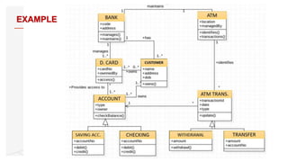
CLASS DIAGRAM
• ClassDiagram Overview
• The components:
• Class
• Properties
• Method
• Relationship
4
5.
§ Class diagramsdescribe the types of objects in the system and
the different types of relationships that exist between them.
§ Is a modeling technique that exists in all object-oriented
development methods.
§ Most commonly used diagrams in UML.
OVERVIEW OF CLASS DIAGRAM
5
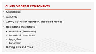
§ Class (class)
§Attributes
§ Activity / Behavior (operation, also called method)
§ Relationship (relationship)
• Associations (Associations)
• Generalization/Inheritance
• Aggregation
• Composition
§ Binding laws and notes
CLASS DIAGRAM COMPONENTS
8
8.
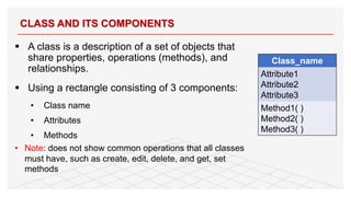
§ A classis a description of a set of objects that
share properties, operations (methods), and
relationships.
§ Using a rectangle consisting of 3 components:
• Class name
• Attributes
• Methods
• Note: does not show common operations that all classes
must have, such as create, edit, delete, and get, set
methods
CLASS AND ITS COMPONENTS
9
Class_name
Attribute1
Attribute2
Attribute3
Method1( )
Method2( )
Method3( )
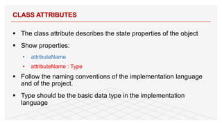
§ The classattribute describes the state properties of the object
§ Show properties:
• attributeName
• attributeName : Type
§ Follow the naming conventions of the implementation language
and of the project.
§ Type should be the basic data type in the implementation
language
CLASS ATTRIBUTES
11
11.
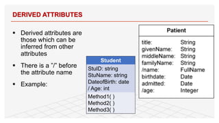
§ Derived attributesare
those which can be
inferred from other
attributes
§ There is a ”/” before
the attribute name
§ Example:
DERIVED ATTRIBUTES
12
Student
StuID: string
StuName: string
DateofBirth: date
/ Age: int
Method1( )
Method2( )
Method3( )
12.
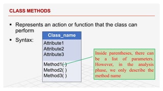
§ Represents anaction or function that the class can
perform
§ Syntax:
CLASS METHODS
13
Class_name
Attribute1
Attribute2
Attribute3
Method1( )
Method2( )
Method3( )
Inside parentheses, there can
be a list of parameters.
However, in the analysis
phase, we only describe the
method name
13.
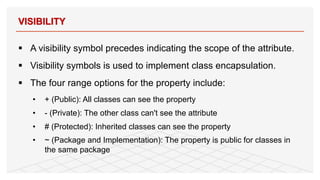
§ A visibilitysymbol precedes indicating the scope of the attribute.
§ Visibility symbols is used to implement class encapsulation.
§ The four range options for the property include:
• + (Public): All classes can see the property
• - (Private): The other class can't see the attribute
• # (Protected): Inherited classes can see the property
• ~ (Package and Implementation): The property is public for classes in
the same package
VISIBILITY
14
14.
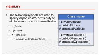
§ The followingsymbols are used to
specify export control or visibility of
attributes and operations (methods):
• + (Public)
• - (Private)
• # (Protected)
• ~ (Package và Implementation)
VISIBILITY
15
Class_name
- privateAttribute
+ publicAttribute
# protectedAttribute
- privateOperation ( )
+ publicOPeration ( )
# protectedOperation ( )
15.
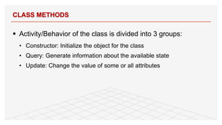
§ Activity/Behavior ofthe class is divided into 3 groups:
• Constructor: Initialize the object for the class
• Query: Generate information about the available state
• Update: Change the value of some or all attributes
CLASS METHODS
16
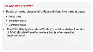
§ Based onroles, classes in UML are divided into three groups:
• Entity class
• Boundary class
• Controller class
§ The EBC (Entity-Boundary-Control) model is abstract version
of MVC (Model-View-Controller) that is often used in
implementation.
CLASS STEREOTYPE
18
18.
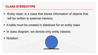
§ Entity class:is a class that stores information of objects that
will be written to external memory.
§ A table must be created in database for an entity class
§ In class diagram, we denote only entity classes.
§ Notation:
CLASS STEREOTYPE
19
19.
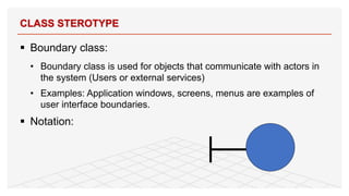
§ Boundary class:
•Boundary class is used for objects that communicate with actors in
the system (Users or external services)
• Examples: Application windows, screens, menus are examples of
user interface boundaries.
§ Notation:
CLASS STEROTYPE
20
20.
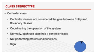
§ Controller class:
•Controller classes are considered the glue between Entity and
Boundary classes
• Coordinating the operation of the system
• Normally, each use case has a controller class
• Not performing professional functions
• Sign:
CLASS STEREOTYPE
21
21.
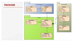
PACKAGE
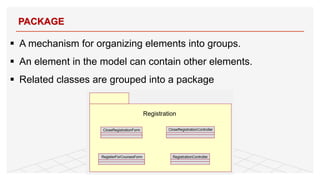
§ A mechanismfor organizing elements into groups.
§ An element in the model can contain other elements.
§ Related classes are grouped into a package
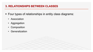
§ Four typesof relationships in entity class diagrams:
• Association
• Aggregation
• Composition
• Generalization
3. RELATIONSHIPS BETWEEN CLASSES
25
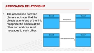
24.
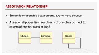
§ Semantic relationshipbetween one, two or more classes.
§ A relationship specifies how objects of one class connect to
objects of another class or itself.
ASSOCIATION RELATIONSHIP
26
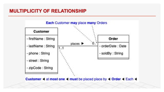
25.
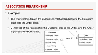
§ Example:
• Thefigure below depicts the association relationship between the Customer
class and the Order class.
• Semantics of the relationship: the Customer places the Order, and the Order
is placed by the Customer.
ASSOCIATION RELATIONSHIP
27
26.
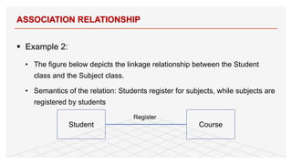
§ Example 2:
•The figure below depicts the linkage relationship between the Student
class and the Subject class.
• Semantics of the relation: Students register for subjects, while subjects are
registered by students
ASSOCIATION RELATIONSHIP
28
Student Course
Register
27.
§ The associationbetween
classes indicates that the
objects at one end of the link
recognize the objects at the
other end and can send
messages to each other.
ASSOCIATION RELATIONSHIP
29
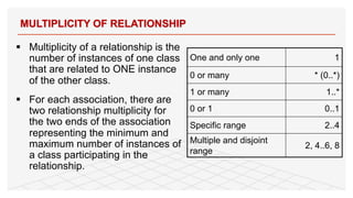
28.
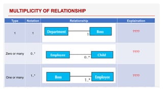
§ Multiplicity ofa relationship is the
number of instances of one class
that are related to ONE instance
of the other class.
§ For each association, there are
two relationship multiplicity for
the two ends of the association
representing the minimum and
maximum number of instances of
a class participating in the
relationship.
MULTIPLICITY OF RELATIONSHIP
30
One and only one 1
0 or many * (0..*)
1 or many 1..*
0 or 1 0..1
Specific range 2..4
Multiple and disjoint
range
2, 4..6, 8
Type Notation RelationshipExplaination
1 1
????
Zero or many 0..*
????
One or many
1..* ????
MULTIPLICITY OF RELATIONSHIP
32
31.
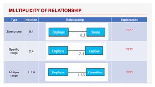
Type Notation RelationshipExplaination
Zero or one 0..1
????
Specific
range
2..4
????
Multiple
range
1..3,5 ????
MULTIPLICITY OF RELATIONSHIP
33
32.
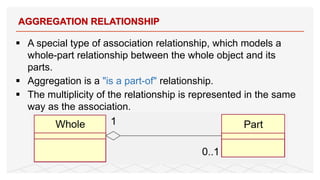
§ A specialtype of association relationship, which models a
whole-part relationship between the whole object and its
parts.
§ Aggregation is a "is a part-of" relationship.
§ The multiplicity of the relationship is represented in the same
way as the association.
AGGREGATION RELATIONSHIP
34
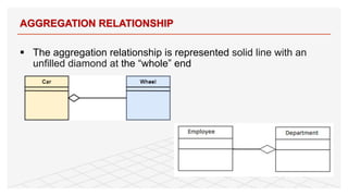
33.
§ The aggregationrelationship is represented solid line with an
unfilled diamond at the “whole” end
AGGREGATION RELATIONSHIP
35
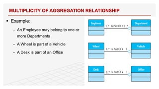
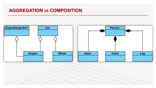
34.
§ Example:
- AnEmployee may belong to one or
more Departments
- A Wheel is part of a Vehicle
- A Desk is part of an Office
MULTIPLICITY OF AGGREGATION RELATIONSHIP
36
35.
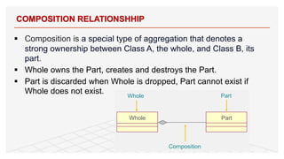
§ Composition isa special type of aggregation that denotes a
strong ownership between Class A, the whole, and Class B, its
part.
§ Whole owns the Part, creates and destroys the Part.
§ Part is discarded when Whole is dropped, Part cannot exist if
Whole does not exist.
COMPOSITION RELATIONSHHIP
37
36.
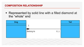
§ Represented bysolid line with a filled diamond at
the “whole” end
COMPOSITION RELATIONSHHIP
38
37.
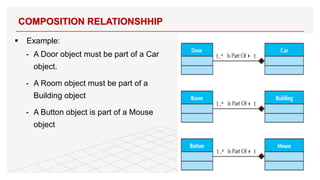
§ Example:
- ADoor object must be part of a Car
object.
- A Room object must be part of a
Building object
- A Button object is part of a Mouse
object
COMPOSITION RELATIONSHHIP
39
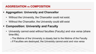
38.
§ Aggregation: Universityand Chancellor
• Without the University, the Chancellor could not exist.
• Without the Chancellor, the University could still exist
§ Composition: University and Faculty
• University cannot exist without faculties (Faculty) and vice versa (share
time-life).
oThe lifetime of the University is closely tied to the lifetime of the Faculty
oIf Faculties are destroyed, the University cannot exist and vice versa
AGGREGATION VS COMPOSITION
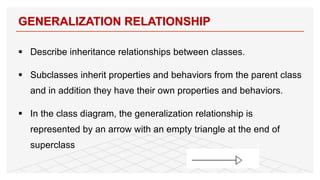
§ Describe inheritancerelationships between classes.
§ Subclasses inherit properties and behaviors from the parent class
and in addition they have their own properties and behaviors.
§ In the class diagram, the generalization relationship is
represented by an arrow with an empty triangle at the end of
superclass
GENERALIZATION RELATIONSHIP
43
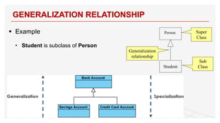
41.
§ Example
• Studentis subclass of Person
GENERALIZATION RELATIONSHIP
44
Student
Super
Class
Sub
Class
Generalization
relationship
Person
42.
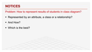
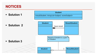
Problem: How torepresent results of students in class diagram?
§ Represented by an attribute, a class or a relationship?
§ And How?
§ Which is the best?
NOTICES
45
§ Association classesand their properties
• In an association relationship, when the multiplicity of two classes are many
(*), an association class can be generated from this relation.
• The association class is not connected to the classes, it is only connected to
the relationship
• Association classes can have attributes, behaviors, and other relationships
NOTICES
47
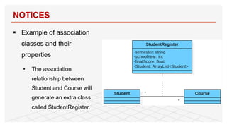
45.
§ Example ofassociation
classes and their
properties
• The association
relationship between
Student and Course will
generate an extra class
called StudentRegister.
NOTICES
48
46.
§ Association classesand their properties:
• The association class describes the properties and behavior of the entity
and exists only when the association exists (Attributes and behaviors are
not related to the objects of the association).
NOTICES
49
47.
§ Tangible objectsand intangible objects
• Subject is a tangible object
• The Course in CourseList can be intangible as it may or may not be open.
• When the Course is open and students are learning, it becomes tangible.
• Avoid mixing tangible and intangible objects together
NOTICES
50
48.
§ Simplify classdiagrams: A class diagram when fully described will
be very complex, then the class diagram needs to be simplified.
§ Ways to simplify class diagrams:
• Show layers in reduced form only (Rectangle includes only layer names)
• Use view mode to display subset of classes
• Packages show cooperation between classes. Classes are divided into
groups based on their relationship
SIMPLIFY CLASS DIAGRAM
52
§ Class responsibilitiesand collaborators
§ Responsibilities is divided into two groups
• know (know)
• doing
§ Collaborators: The layers that participate in the use case
business process will form a group of layers that cooperate with
each other.
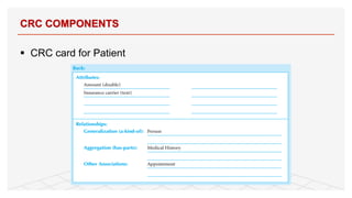
CRC COMPONENTS
56
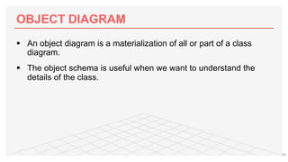
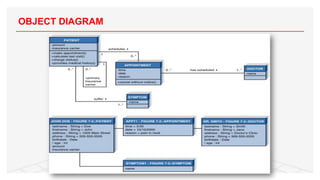
§ An objectdiagram is a materialization of all or part of a class
diagram.
§ The object schema is useful when we want to understand the
details of the class.
59
NOTICE
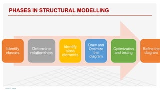
§ Don't tryto use all the different symbols
§ Unnecessary to model everything,just focus on the important
information
64
61.
§ There areno general rules for class definition.
§ Some techniques to identify classes and components:
1. Analyze use case scenario
2. Find a list of popular objects
3. Search from Patterns.
1. IDENTIFY CLASSES
65
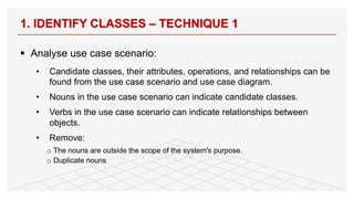
62.
§ Analyse usecase scenario:
• Candidate classes, their attributes, operations, and relationships can be
found from the use case scenario and use case diagram.
• Nouns in the use case scenario can indicate candidate classes.
• Verbs in the use case scenario can indicate relationships between
objects.
• Remove:
o The nouns are outside the scope of the system's purpose.
o Duplicate nouns
1. IDENTIFY CLASSES – TECHNIQUE 1
66
63.
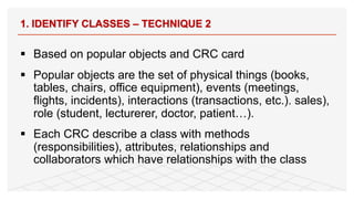
1. IDENTIFY CLASSES– TECHNIQUE 2
§ Based on popular objects and CRC card
§ Popular objects are the set of physical things (books,
tables, chairs, office equipment), events (meetings,
flights, incidents), interactions (transactions, etc.). sales),
role (student, lecturerer, doctor, patient…).
§ Each CRC describe a class with methods
(responsibilities), attributes, relationships and
collaborators which have relationships with the class
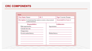
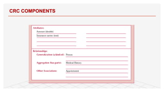
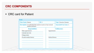
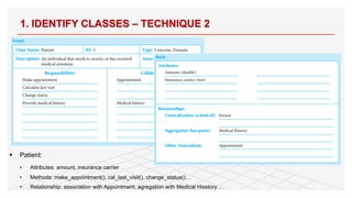
64.
1. IDENTIFY CLASSES– TECHNIQUE 2
§ Patient:
• Attributes: amount, insurance carrier
• Methods: make_appointment(), cal_last_visit(), change_status()…
• Relationship: association with Appointment, agregation with Medical Hisstory…
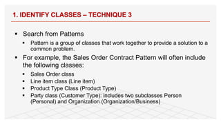
65.
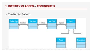
§ Search fromPatterns
§ Pattern is a group of classes that work together to provide a solution to a
common problem.
§ For example, the Sales Order Contract Pattern will often include
the following classes:
§ Sales Order class
§ Line item class (Line item)
§ Product Type Class (Product Type)
§ Party class (Customer Type): includes two subclasses Person
(Personal) and Organization (Organization/Business)
1. IDENTIFY CLASSES – TECHNIQUE 3
69
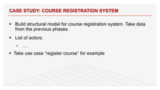
§ Build structuralmodel for course registration system. Take data
from the previous phases.
§ List of actors:
• ….
§ Take use case “register course” for example
CASE STUDY: COURSE REGISTRATION SYSTEM
71
68.
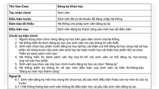
Tên Use CaseĐăng ký khóa học
Tác nhân chính Sinh viên
Điều kiện trước Sinh viên đã có tài khoản để đăng nhập hệ thống
Đảm bảo tối thiểu Hệ thống cho phép sinh viên đăng ký lại
Điều kiện sau Sinh viên đăng ký thành công các môn học đủ điều kiện
Chuỗi sự kiện chính
1. Người dùng chọn chức năng đăng ký học trên giao diện chính của hệ thống
2. Hệ thống hiển thị form đăng ký học cho sinh viên với các thông tin cần thiết
3. Sinh viên chọn học phần muốn đăng ký học lại/học cải thiện (có thể đăng ký học cùng một số học
phần với khóa trước nếu sinh viên phải học lại hoặc muốn học cải thiện học phần đó) và chọn
“Hiển thị danh sách môn học”
4. Hệ thống hiển thị danh sách các lớp học tín chỉ mà sinh viên có thể đăng ký học tương
ứng với các học phần
5. Sinh viên lựa chon các lớp học mình muốn đăng ký học và chọn “Đăng ký”
6. Hệ thống kiểm tra thông tin về các môn điều kiện của sinh viên và hiển thị thông báo
“Đăng ký môn học thành công”
Ngoại lệ
6.1. Sinh viên đăng ký môn học trong khi chưa học đủ các môn điều kiện hoặc còn nợ môn từ các kỳ
trước
5.1.1.Hệ thống thông báo sinh viên không đủ điều kiện học và yêu cầu sinh viên đăng ký lại.
69.
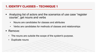
§ Analyzing listof actors and the scenarios of use case “register
course”, get nouns and verbs
• Nouns are candidates for classes and attributes
• Verbs are candidates for methods of classes and relationships
§ Remove:
• The nouns are outside the scope of the system's purpose.
• Duplicate nouns
1. IDENTIFY CLASSES – TECHNIQUE 1
73
70.
§ For example,in the course registration system:
• Nouns that are system actors such as Student, Lecturer, Teacher, etc. are
candidate classes for the system.
• Nouns that appear in use case scenarios such as Subject, Course are
candidate classes.
• Verbs are …..
1. IDENTIFY CLASSES – TECHNIQUE 1
74
71.
§ Remove nouns:
•Some nouns that describe properties/attributs such as Full name, date of
birth, address, course name, number of credits, etc. are attributes for
classes.
• But some nouns may not be class. For example, the noun System “Hệ
thống” is not a class, it is just a boundary between the software to be built
and the external environment.
1. IDENTIFY CLASSES – TECHNIQUE 1
75
72.
§ Find froma list of popular objects
§ The analyst can derive other classes from the set of physical
things such as list of course, catalogue, books, rooms, tables,
chairs, office equipment), events (meetings, flights, incidents),
interactions (registration, studentresults). sales), role (student,
lecturerer,… ).
1. IDENTIFY CLASSES – TECHNIQUE 2
76
73.
§ Define oneof the relationship types:
• Association
• Aggregation
• Composition
• Generalization
• Dependency
§ Note: Sometimes just using the association relationship is
enough, it is not necessary to use aggregation or aggregation
2. IDENTIFY RELATIONSHIPS BETWEEN CLASSES
78
74.
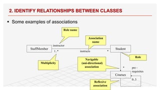
§ Some examplesof associations
2. IDENTIFY RELATIONSHIPS BETWEEN CLASSES
79
StaffMember Student
1..* *
instructs
instructor
Association
name
Role name
Multiplicity
Navigable
(uni-directional)
association
Courses
pre -
requisites
0..3
Reflexive
association
Role
*
75.
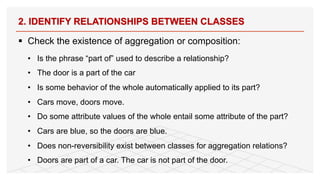
§ Check theexistence of aggregation or composition:
• Is the phrase “part of” used to describe a relationship?
• The door is a part of the car
• Is some behavior of the whole automatically applied to its part?
• Cars move, doors move.
• Do some attribute values of the whole entail some attribute of the part?
• Cars are blue, so the doors are blue.
• Does non-reversibility exist between classes for aggregation relations?
• Doors are part of a car. The car is not part of the door.
2. IDENTIFY RELATIONSHIPS BETWEEN CLASSES
80
76.
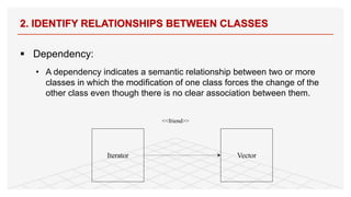
§ Dependency:
• Adependency indicates a semantic relationship between two or more
classes in which the modification of one class forces the change of the
other class even though there is no clear association between them.
2. IDENTIFY RELATIONSHIPS BETWEEN CLASSES
81
Iterator Vector
<<friend>>
§ Class attribtes:
<visibility><name>: <type> <number of Objects> = <default> (<ValueLimit> )
• Visibility: indicates the access scope of the attribute. The four visibility identifiers
for the attribute include:
+ (Public): All classes can see the property
- (Private): The other class can't see the attribute
# (Protected): Visible for derived classes
~ (Package and Implementation): The property is public for classes in the same package
• name: is a string representing the attribute name.
• type: is the data type of the attribute.
• Number of objects: Specifies the number of objects declared for the property
corresponding to a default that is the default initial value (if any) of the property.
• ValueLimit: is to limit the values for the attribute (this information is optional)
3. DEFINE CLASS ELEMENTS
84
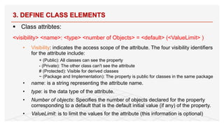
79.
§ Class attributeexample:
• purchaseDate:Date[1] = “01-01-2000” (Saturday)
§ Derived attributes
• /age, for example age can be calculated based on date of birth and current
year
3. DEFINE CLASS ELEMENTS
85
80.
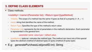
§ Class methods:
<visibility><name>(Parameter list): <Return type>{typeMethod}
• Visibility: The scope of a method has the same 4 types as that of a property (+, #, -, ~)
• name: string that identifies the name of the method.
• Return Type: Specifies the type of the method's return value.
• Parameter List: represents the list of parameters in the method's declaration. Each parameter
is represented in the general form:
parameter name: value type = default value.
• typeMethod: optional, indicates the method type. The method can have one of the special
types like abstract (method of abstract type) or query (method of query type).
§ E.g: generatePurchaseList(prodID:int): String
3. DEFINE CLASS ELEMENTS
86
81.
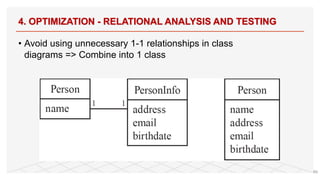
4. OPTIMIZATION -RELATIONAL ANALYSIS AND TESTING
• Avoid using unnecessary 1-1 relationships in class
diagrams => Combine into 1 class
89
82.
HOMEWORK
§ Build structuralmodels for your group’s system
• Identify all classes of the system.
• Build class diagram and optimize classes if necessary
90


![§ Class attribute example:
• purchaseDate:Date[1] = “01-01-2000” (Saturday)
§ Derived attributes
• /age, for example age can be calculated based on date of birth and current
year
3. DEFINE CLASS ELEMENTS
85](https://image.slidesharecdn.com/lecture05-structuralmodeling-250519130941-a11a9c09/85/Lecture05-Structural-Modeling-for-students-pdf-79-320.jpg)