This document provides an overview of parallel computing and parallel processing. It discusses:
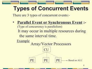
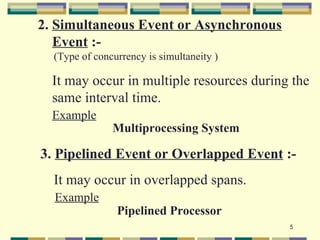
1. The three types of concurrent events in parallel processing: parallel, simultaneous, and pipelined events.
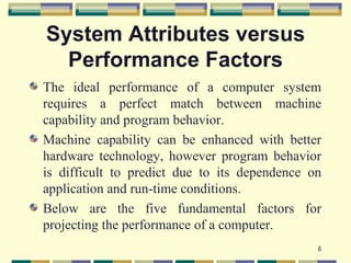
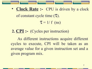
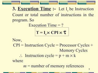
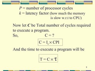
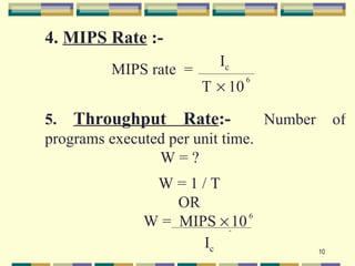
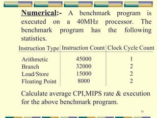
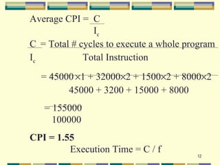
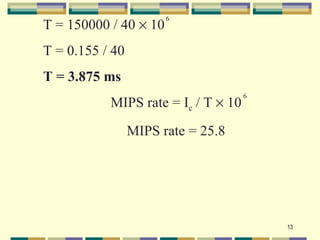
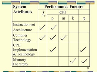
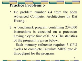
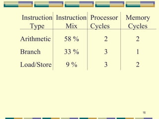
2. The five fundamental factors for projecting computer performance: clock rate, cycles per instruction (CPI), execution time, million instructions per second (MIPS) rate, and throughput rate.
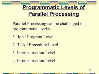
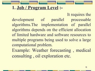
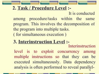
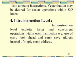
3. The four programmatic levels of parallel processing from highest to lowest: job/program level, task/procedure level, interinstruction level, and intrainstruction level.